


VT-4006 Service Manual
CUSTOMER MODEL: VT-4006

VT-4006 Service Manual
VT-4006 Service Manual
Table of Contents
Page
General Section..........................................................................................2-4
Caution/Warnings
Safe Warnings
Precautions
Software Upgrade
Circuit Diagram and Component Layout.......................................................5-27
MPEG IC Block Diagrams
Power supply Circuit Diagram and Component Layout
MPEG Circuit Diagram and Component Layout
Front panel Circuit Diagram and Component Layout
Out Board Circuit Diagram and Component Layout
Servicing Procedures..............................................................................28-34
Power Supply Trouble Service Flow Chart
Read Disc Trouble Service Flow Chart
Video Trouble Service Flow Chart
Composite Analogy Audio Trouble Service Flow Chart
Digital Audio Trouble Service Flow Chart
Front Control Trouble Service Flow Chart
Remote Control Trouble Service Flow Chart
Parts List.............................................................................. ..................35-39
Power Part List
MPEG Part List
Front Panel Part List
Out Board Part List
Page 1
VT-4006 Service Manual
1. General Section
1.1 Cautions/Warnings
1.1.1 Product Safety Notice
Parts marked with the symbol in the schematic diagram have critical char-
acteristics.
Use ONLY replacement pares recommended by the manufacturer.
It is recommended that the unit be operated from a suitable DC supply or batter-
ies during initial check out procedures.
CAUTION
RISK OF ELECTRIC SHOCK
DO NOT OPEN
WARNING HIGH VOLTAGE INSIDE TO PREVENT
ELECTRICAL SHOCK DO NOT REMOVE ANY CO-
VER OR SCREW. REFER ALL SERVICING TO QU-
ALIFIED SERVICE PERSONNEL. DO NOT ALLOW
THIS PRODUCTION BE EXPOSED TO RAIN OR
MOISTURE. DISCONNECT THIS MAINS PLUG
FROM THE SUPPLY SOCKET WHEN NOT IN
USE.
1.1.2 Leakage Current Check/Resistance Check
Before returning the unit to the customer, make sure you make either (1) a
leakage current check or (2) a line to insulated resistance check.
If the leakage current exceeds 0.5 milliamps , or if the resistance from chas-
sis to either side of the power cord is less than 240 K ohms, the unit is defec-
tive.
WARNING: DO NOT return the unit to the customer until the problem or loca-
ted and corrected.
1.2. Safe Warnings
1.2.1. Protection of Eyes from Laser Beam
To protect eyes from invisible laser beam during servicing
DO NOT LOOK AT THE LASER BEAM
Page 2

VT-4006 Service Manual
1.2.2 Laser Caution
CAUTION
Adjusting the knobs, switches, and controls , ect. Or taking actions not
specified herein may result in a harmful emission of laser beams.
This CD Changer must be adjusted and repaired only by qualified serv ice
personnel.
CAUTION- INVISIBLE LASER RADIATION WHEN OPEN AND INTERLOCKS
DEFEATED AVOID EXPOSURE TO BEAM.
VORSICHTI- UNSICHTBARE LASERSTRAHLUNG TRITT AUS. WENN DECKEL
GEOFFNET UND WENN SICHERHEITSVERRIEGELUNG
uBERBRuCKT IST. NICHT DEM STRAHL AUSSETZENI
VARNING- OSYNLIG LASERSTRALNING NAR DENNA DEL AR OPPNAD OCH
SPARR AR URKOPPLAD STRALEN AR FARLIG.
ADVARSEL-USYNLIG LASERSTRALING VED ABNING NAR
SIKKERHEADSAFBRYDERE ER UDE AF FUNKTION. UNDGA
UDSAETTELSE FOR STRALING.
CLASS 1 LASER PRODUCT
LUOKAN 1 LASERLAITE
KLASS 1 LASERAPPARAT
THIS IS COMPACT DISC PLAYER IS CLASSIFIED AS A CLASS LASER
PRODUCT.
THE LASS 1 LASER PRODUCT LABEL IS LOCATED ON THE REAR EX TERIOR.
1.3. Precautions
1.3.1. ESD Precautions in Repairing
1.3.1.1 Do not apply excessive pressure on the mechanical parts (movi ng pares), including the Pickup Block, as extremely high mechanical pre cision or required in these parts.
1.3.1.2 When soldering the microprocessor and signal processing IC s,
use a ceramic soldering iron or a soldering iron whose metal part is grou nded since they are not resistant to static electricity.
1.3.1.3 When removing the solder or soldering the laser shorting lands
for the Pickup Block, use a ceramic soldering iron or a soldering iron wh ose metal part is grounded since the laser diode or not resistant to static
electricity.
Page 3

VT-4006 Service Manual
1.3.2. DVD Loading Unit Precautions When handing the
Mechanism Block
1.3.2.1 Do not loosen any screws in the Pickup Block.
1.3.2.2 Do not adjust any screws in the Mechanism Block except for
Tilt Adjust Screws , as they are adjusted precisely at the factory.
1.3.2.3 Replacement of the Pickup Block is impossible. Always repl ace the Traverse Ass s when the Pickup Block needed to be replace .
Do not touch the lens or lens holder of the Pickup Block.
1.3.2.4 The Guide Rails of the Pickup Block are greased. Take care wh en handing.
1.3.2.5 When you try to slide the Pickup Block, do not press or pull it
directly, Always turn the dive gears with your fingers.
1.3.2.6 Be sure that the anti-slipping rubber on the turnable or clean.
If there is dust or it is greasy,clean the part with the liquid that contains
50% each of alcohol and water.
1.3.2.7 When removing the Mechanism P.C.B. Ass s, you need to sho rt-circuit the laser diode shorting lands beforehand.
1.4. Software Upgrade
You can upgrade DVD player using the software we provide as following step:
Creating a software upgrade CD
Use only a new CD-R/CD-RW(not an erased one)
Give the CD a name of your choice(e.g. Version and unit name)
Burn the unpacked documents on the CD-D/CD-RW.
The root directory(uppermost level)of the software upgrade CD.
Attention: If a failure should occur during the software upgrade(e.g a mains failure),
it may happen that the units function and a restart of the upgrade function are no
longer possible.If this should be the case,you must replace the intergraded FLASH
ICs with preprogrammed ICs (see corresponding spare parts list).
Insert the upgrade CD (see corresponding spare parts list) and observe the
hints on the display and on the screen of the TV set.
Carry out an initialization of the set.
Displaying the Software Version Number
Press one after the other the STOP and EJECT buttons on the unit.
Press the OSD with the remote control.
Using the cursor buttons on the remote control ,select the software version
MICRO Version or CUSTOMER VERSION .The respective software version
number then is displayed.
Page 4
VT-4006 Service Manual
2. Circuit Diagram and Component Layout
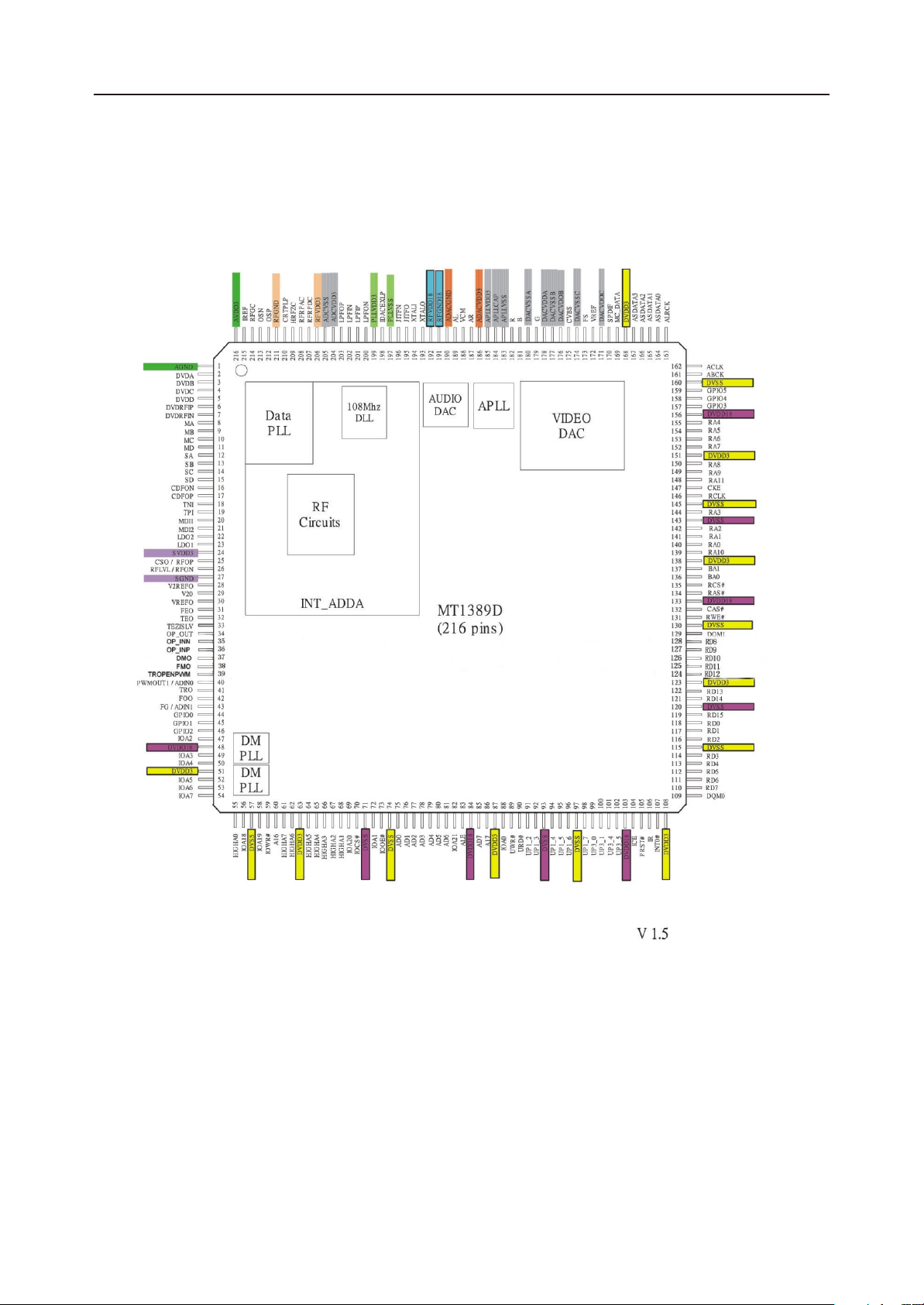
2.1 MPEG IC Block Diagrams
Page 5
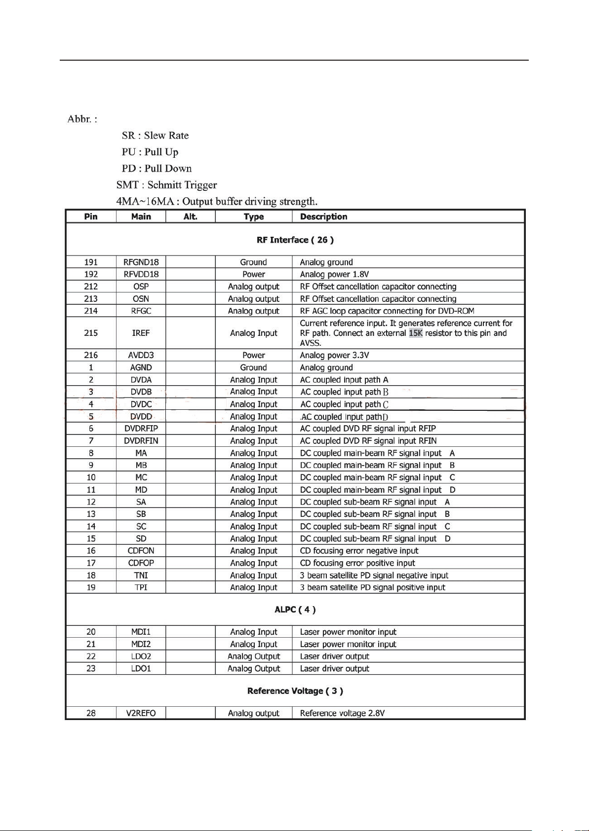
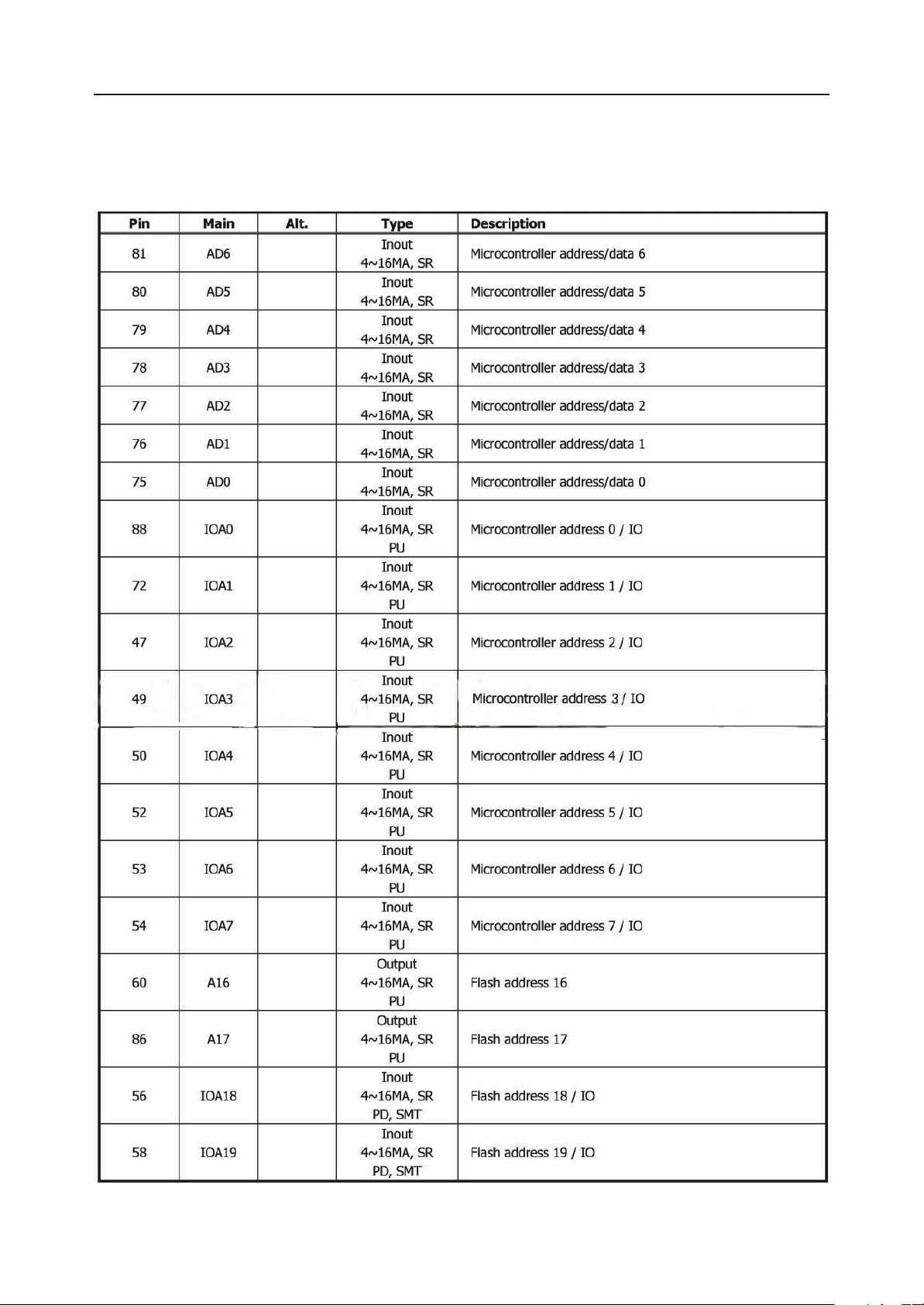
Table1: MT1389D Pin Description
VT-4006 Service Manual
Page 6
VT-4006 Service Manual
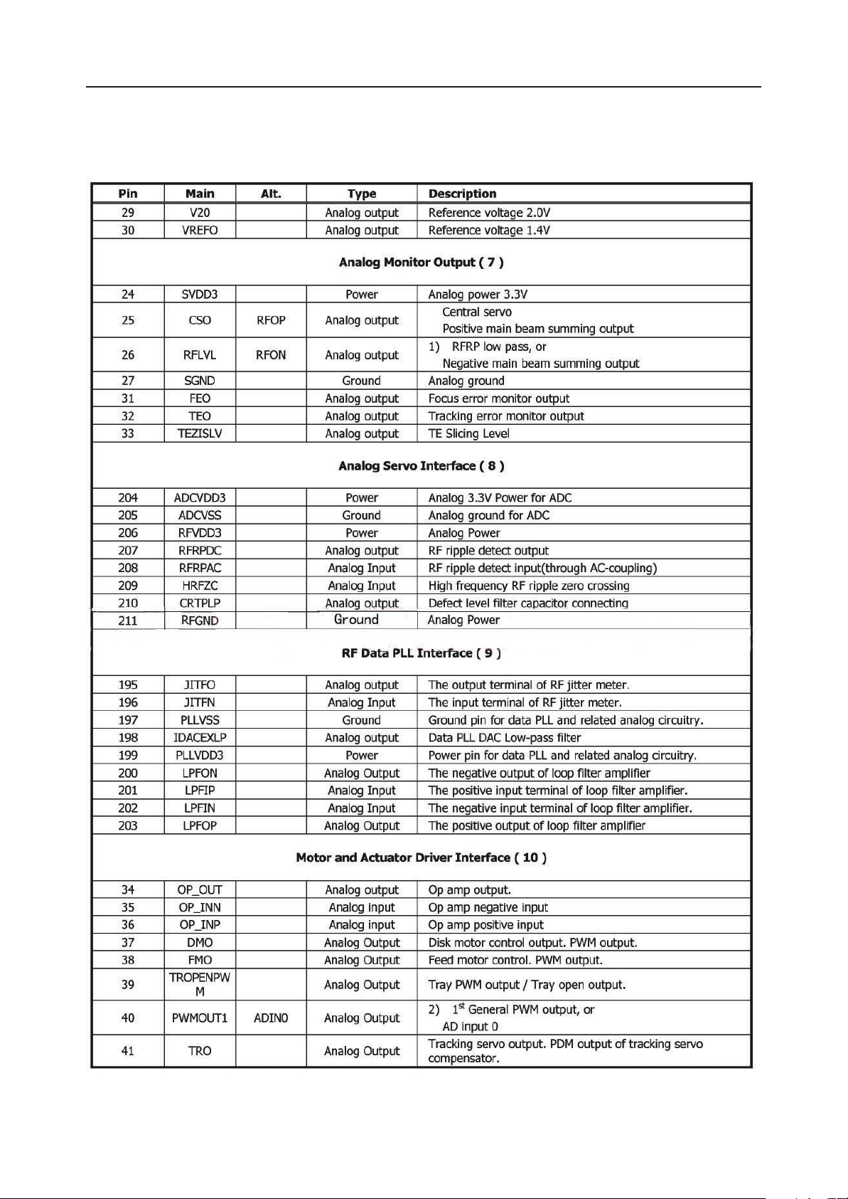
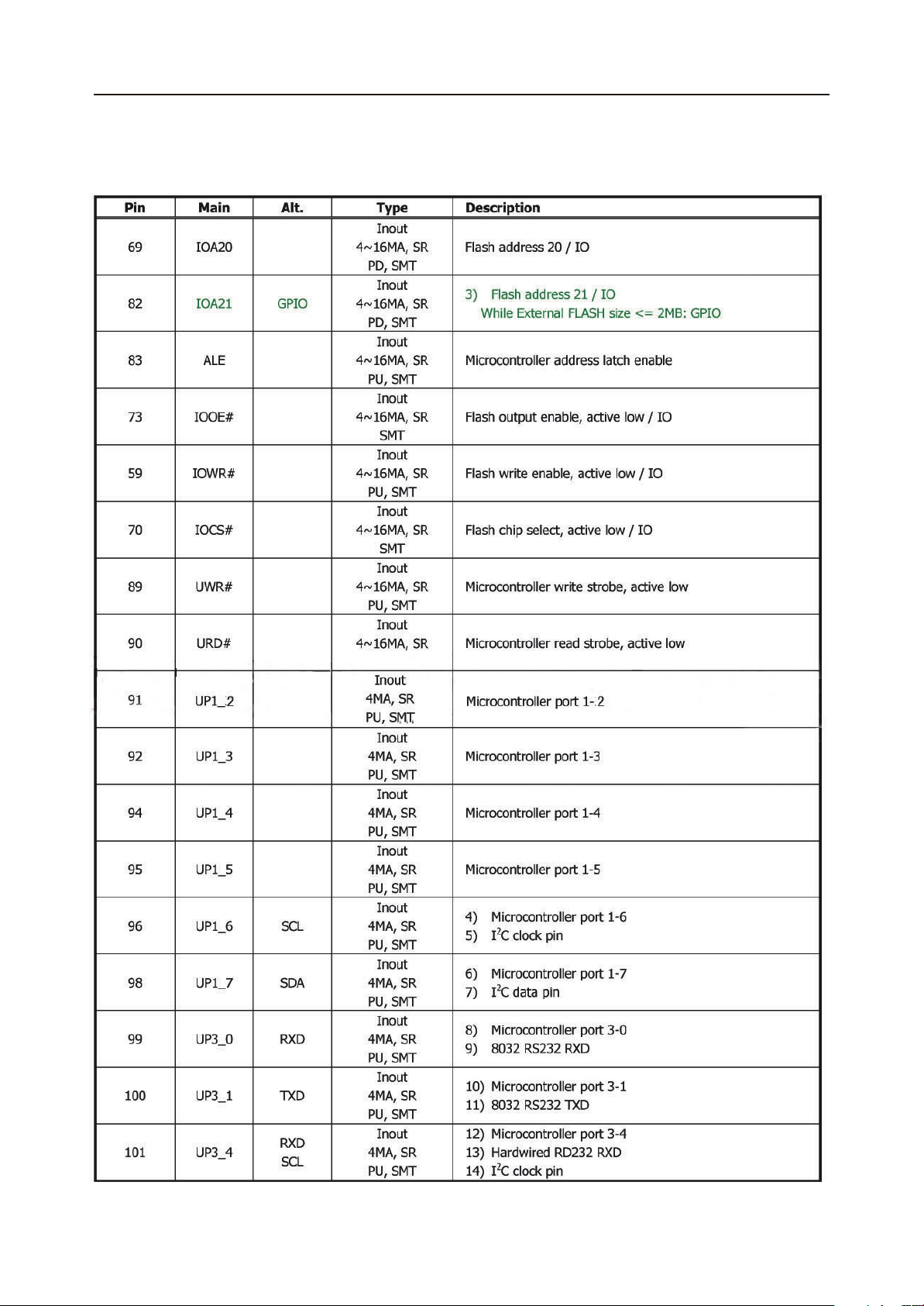
Table1: MT1389D Pin Description (continued)
Page 7

VT-4006 Service Manual
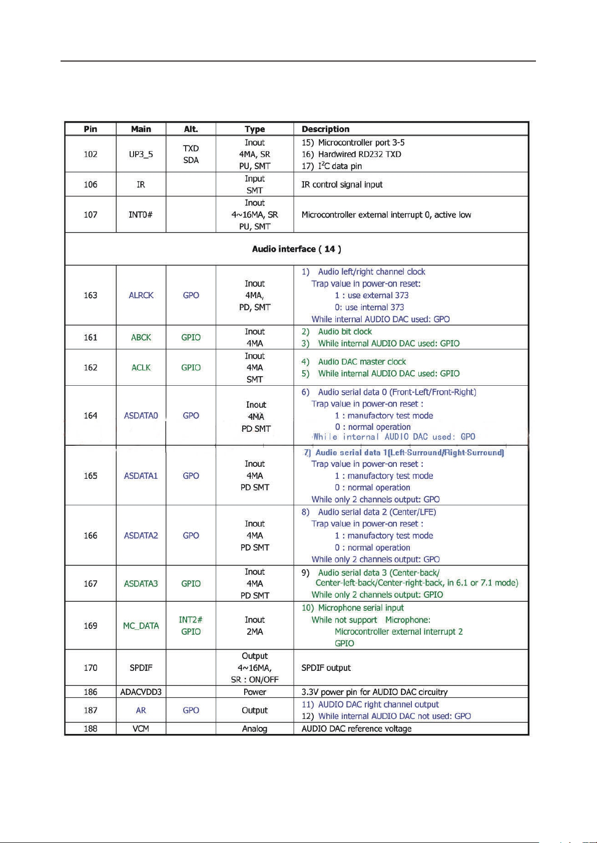
Table1: MT1389D Pin Description (continued)
Page 8
VT-4006 Service Manual
Table1: MT1389D Pin Description (continued)
Page 9
VT-4006 Service Manual
Table1: MT1389D Pin Description (continued)
Page 10
VT-4006 Service Manual
Table1: MT1389D Pin Description (continued)
Page 11
 Loading...