


VT-3454
CAUTION: Before servicing the chassis, read the "Important Service Safety Information"
section on page 2 of this manual.
PORTABLE CD PLAYER with MP3,USB,SD and RADIO
STNETNOC
IMPORTANT SERVICE SAFETY INFORMATION
DISASSEMBLY INSTRUCTIONS
BLOCK DIAGRAM
WIRING DIAGRAM
PRINTED CIRCUIT BOARDS
SCHEMATIC DIAGRAMS
EXPLODED VIEW
EXPLODED VIEW PART LIST
SPECIFIACTION
PART LIST 17-27
6-8
9-11
12
13
14-16
2
3
4
5

IMPORTANT SERVICE SAFETY INFORMATION
1.
SAFETY PRECAUTIONS
Before returning a unit to the customer, always make a safety check of
the entire unit, including, but not limited to the following items:
a. Be sure that no built-in protective devices are defective and/or have
been defeated during servicing.
(1)
Protective shields ar e provided to protect both the technician and
the customer. Correctly replace all missing protective shields
including any removed for servicing convenience.
(2)
When reinstalling the chassis and/or other assemblies in the
cabinet, be sure t put back in place all protective devices, including,
but not limited to, nonmetallic control knobs, insulating fishpapers,
adjustment and compartment covers/shields and isolation resisto r/
capacitor networks. Do not operate this unit or permit it to be
operated without all protective devices correctly installed and
functioning.
b.
Be sure that there are no cabinet openings through which an adult or
child might be able to insert their fingers and contact a hazardous
voltage. such openings include, but are not limited to, excessively wide
cabinet ventilation slots, and an improperly fitted and/or incorrectly
secured cabinet back cover.
c.
" Leakage Current Hot Check - With the unit completely reassembled,
plug the AC line cord directly into a (EU voltage)V AC outlet. (Do not
use an isolation transformer during this test.) Use a leakage current
tester or a metering system that complies with IEC60990 figure 4. With
the unit AC switch first in the ON position and then in the OFF position ,
measure from a known earth ground (metal water pipe, conduit, etc.),
especially any exposed metal parts that offer an electrical return path to
the chassis. Any current measured must not exceed the following
values:
. for a.c.: U1 = 35 V (peak) and U2 = 0,35 V (peak);
. for d.c.: U1 = 1,0 V.
NOTE: The limit values of U2 = 0,35 V (peak) for a.c. and U1 = 1,0 V for
d.c. correspond to the values 0,7 mA(peak) a.c. and 2,0 mA d.c.
The limit value U1 = 35 V (peak) for a.c. corresponds to the value 70
mA (peak) a.c. for frequencies greater than 100 kHz.
Reverse the unit power cord plug in the outlet and repeat test. ANY
MEASUREMENTS NOT WITHIN THE LIMITS SPECIFIED HERENIN
INDICATE A POTENTIAL SHOCK HAZARD THAT MUST BE
ELIMINATED BEFORE RETURNING THE UNIT TO THE CUSTOMER.
"
(READING SHOULD
NOT BE ABOVE
0.5mA)
AC Leakage Test
DEVICE
UNDER
TEST
2-WIRE CORD
ALSO TEST WITH
PLUG REVERSED
(USING AC ADAPTER
PLUG AS REQUIRED)
d.
Insulation Resistance Test Cold Check
Unplug the power supply cord and connect a jumper wire between the
two prongs of the plug.
Turn on the power switch of the unit.
Measure the resistance with an ohmmeter between the jumpered AC
plug and each exposed metallic cabinet part on the unit, such as
screwheads, antenna, control shafts, handle brackets, etc. When the
exposed metallic part has a return path to the chassis, the reading
should be between 1 and 5.2 megohms. When there is no return path to
the chassis, the reading must be “infinite”. If it is not within the limits
specified, there is the possibility of a shock hazard, and the unit must be
repaired and rechecked before it is returned to the customer.
TEST ALL
EXPOSED METAL
SURFACES
+
LEAKAGE
CURRENT
TESTER
EARTH
GROUND
ANTENNA
TERMINAL
EXPOSED
METAL
PART
2.
PRODUCT SAFETY NOTICE
OM
OHMMETER
Some electrical and mechanical parts have special safety related
characteristics which are often not evident from visual inspection, nor
can the protection they give necessarily be obtained by replacing them
with components rated for high er voltage, wattage, etc. Parts that
have special safety characteristics are identified by a on
schematic and parts list. Use of a substitute replacement that does not
have the same safety characteristics as the recommended
replacement part might create shock, fire, and/or other hazards.
Product safety is under review continuously and new instructions are
issued whenever appropriate.
SERVICING PRECAUTIONS
3.
CAUTION”Before servicing the unit covered by this service manual
and its supplements read and follow the SAFETY PRECAUTIONS on
this page. NOTE”If unforeseen circumstances create a conflit
between the following servicing precautions and any of the safety
precautions, always follow the safety precautions. Remembe r: Safety
First.
General Servicing Precautions.
a. Always unplug the unit’s AC power cord from the AC power
source before:
(1) removing or reinstalling any component, circuit board, module, or
any other unit assembly.
(2) disconnecting or reconnecting any unit electrical plug or other
electrical connection.
(3) connecting a test substitute in parallel with an electrolytic
capacitor in the unit.
Caution: A wrong part substitution or incorrect polarity installation
of electrolytic capacitors may result in an explosion
hazard.
b. Do not defeat any plug/socket B+ voltage interlocks with which
the unit covered by this service manual might be equipped.
c. Do not apply AC power to this unit and/or any of its electrical
assemblies unless all solid-state device heat sinks are correctly
installed.
d. always connect a test unit instrument’s ground lead to the unit’s
chassis ground before connecting the test instrument’s positive
lead. Always remove the test instrument’s ground lead last.
LASER PRECAUTIONS
4.
WARNING!!
When servicing, (in case it is necessary to confirm Laser Beam
1.
Emission) be sure not to place your eyes any closer than 1 ft or
30cm from the surface of the Objective Lens on the Opticval
Pickup Block.
HANDLING THE LASER PICKUP
2.
Laser diodes are extremely susceptible to damage from static
electricity. Even if a static discharge does not ruin the diode, it can
shorten its life or cause it to work improperly. When replacing the
pickup, use a conductive mat on the floor and desk and wear a
wrist band connected to ground through a 1M ohm resistor to
protect the laser diode from static damage. If the lens should get
dusty, blow off the dust carefully from the object.
3.
There are no adjustable parts in the pickup assembly. If it is
defective, replace the whole pickup assembly.
CAUTION:
USE OF CONTROLS, ADJUSTMENTS OR PERFORMANCE OF
PROCEDURES HEREIN MAY RESULT IN HAZARDOUS
RADIATION EXPOSURE.
DANGER:
IF INTERLOCK FAILS OR IS DEFEATED, THE LASER LIGHT IS
ABLE TO FUNCTION. THE LASER IS INVISIBLE, AVOID DIRECT
EXPOSURE TO BEAM.
2

DISASSEMBLY INSTRUCTIONS
1) ROTATE THE UNIT TO EXPOSE THE BACK SIDE AND BOTTOM SIDE.
2) REMOVE THE 8 SCREWS AS SHOWN IN FIG.1.
FIG.1
3

BLOCK DIAGRAM
4

BLOCK DIAGRAM
PH1
CN102
MAIN BOARD
CN84
CN91
CN6
DISPLAY BOARD
CN5
CN87
CN4
JACK BOARD
CN3
5

LAYOUT DIAGRAM-MAIN BOARD
TOP SIDE
6

LAYOUT DIAGRAM-MAIN BOARD
BOTTOM SIDE
7

LAYOUT DIAGRAM-DISPLAY BOARD
8

SCHEMATIC DIAGRAM-CD/MP3/WMA/SD CARD PART
9

SCHEMATIC DIAGRAM-TUNER/POWER PART
10
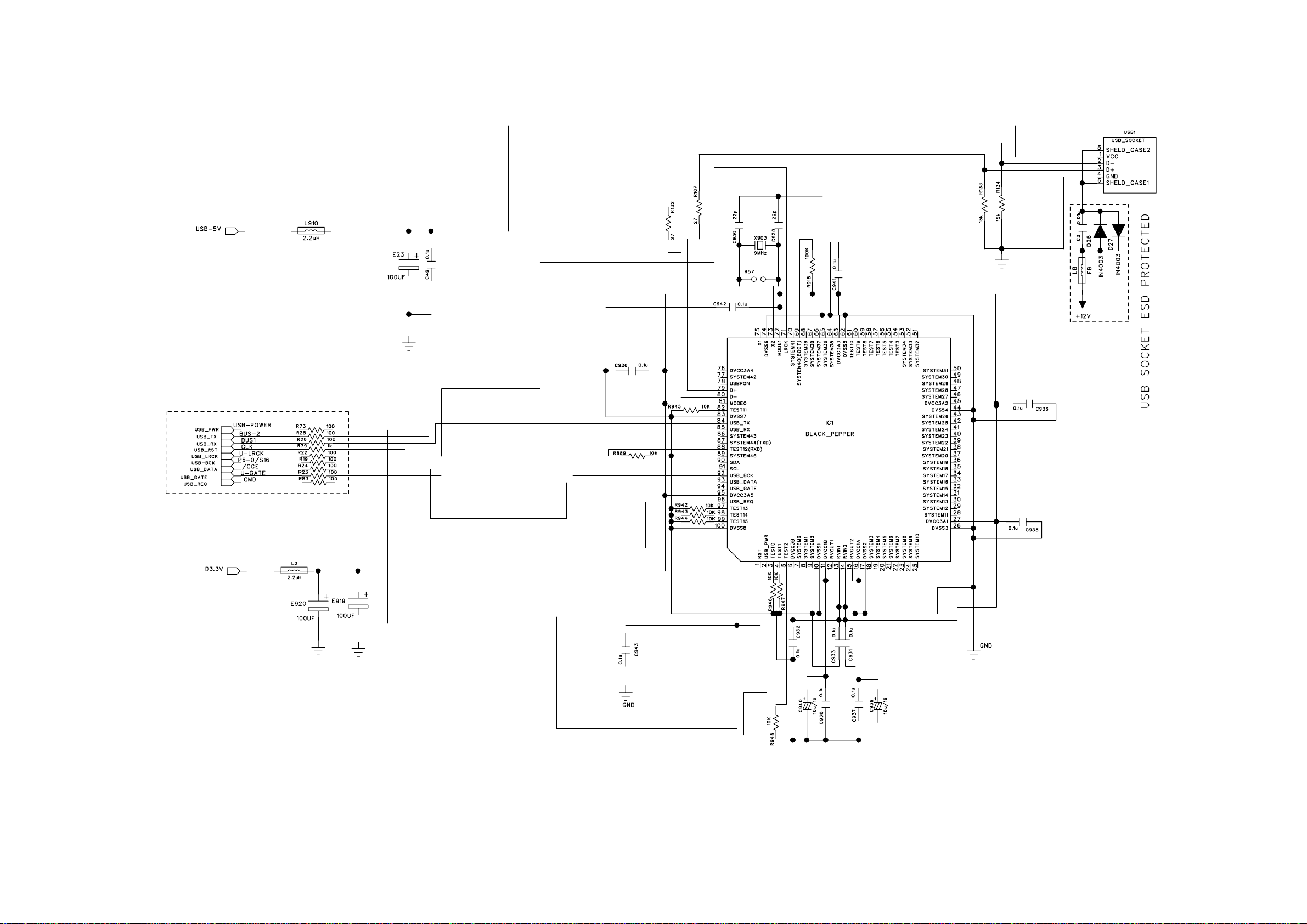
SCHEMATIC DIAGRAM- USB SOCKET PART
11
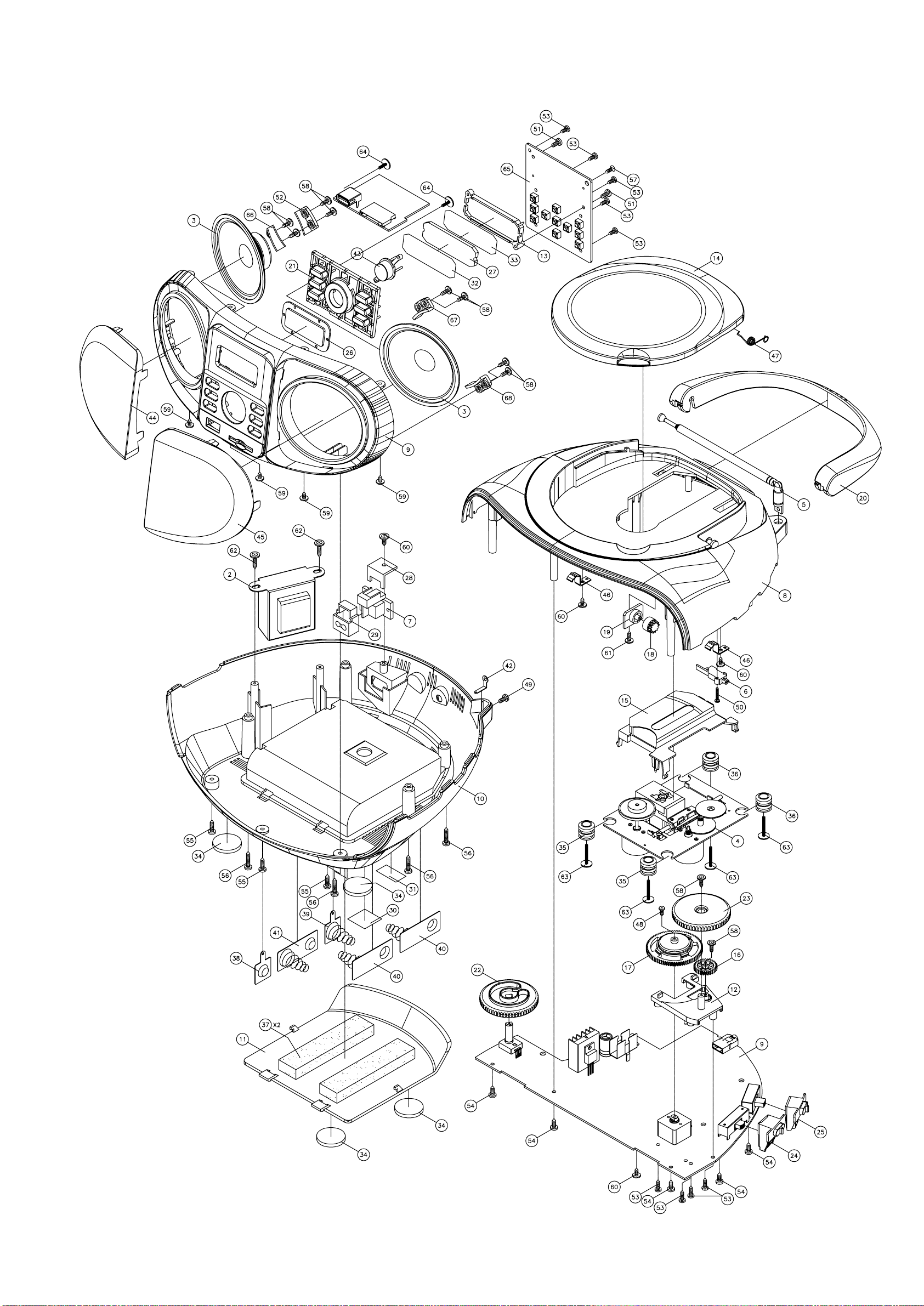
EXPLODED VIEW
12
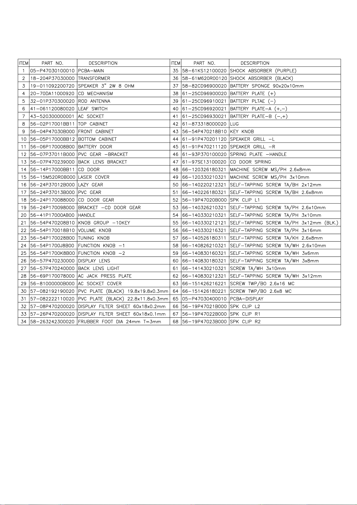
EXPLODED VIEW PART LIST
13

SUPPLY VOLTAGE : AC230V 50HZ SPEAKER:
REF. OUTPUT:
BAND SECTION: CD
AUDIO FREQ: KHz
ITEM Spec. Limit 1 2 3 UNIT
REMARKS : TEST BY: APPROVED:
SPECIFICATION
8OHM
50 MW
)
16. AUX Frequency Response:
15. AUX POWER OUTPUT(1KHZ 1000Mv
)
S
01. Channel Balance 1KHZ/0dB (TCD-782) 1 2 dB
02. THD (1KHz/-10dB)(TCD-782) 0.5 1 %
(1KHz/0dB)(TCD-782
04. Channel Separation (1khz/0dB) (TCD-782)
1KHz 0 0 dB
05. Frequency Response:
06 THD At Max Vol Control (1Khz/0dB)
07 POWER Output 1khz/0dB 10%
08 Accese Time (Short) (TCD-782)
(Long) (TCD-782)
CBS( noitpurretnI .90
AUX 500Mv
14. Channel Balance
CD/USB/CARD -6dB
AM 60% 100dB
FM 45KHZ 60dB
10 KHz +/-2 +/-4 dB
100HZ Bd3-/+0
1KHZ 00 dB
16KHZ Bd3-/+0
%0351
W2.15.1
W2.15.1
Bd0555FPB O/W N/S .30
Bd5304
Bd 4-/+2-/+zH 721
Bd4-/+2-/+zHK 61
s64
s218
mu0080001)A444
mu006008)A444 CBS( toD kcalB .01
mu5657)A444 CBS( tnirP regniF .11
mu yticirtneccE .21
mu 006008)137-DCT( noitaiveD lacitreV .31
Bd3-/+0
Bd3-/+0
Bd3-/+0
BdFERFER
14
SUPPLY VOLTAGE : AC230V 50HZ SPEAKER:
BAND SECTION: AM Antenna : LOOP :
AUDIO FREQ: 1KHz MOD./DEV
.
ITEM Spec. Limit 1 2 3 UNIT
REMARKS : TEST BY: APPROVED:
SPECIFICATION
REF. OUTPUT:
8OHM
50 MW
50 OHM
S
01. Tuning Range Low End 515 +15/-10 KHz
High End 1635 +20/-28 KHz
02. I. F.
03. MAX.Sens. 999 KHz 56 62 dBuv/m
04. Sen. for -20dB S/N 999 KHz 62 66 dBuv/m
06. Image Rejection at 1404KHz 30 25 db
07. Tweet at 5mV/m 2 x 1.F. 5 15 %
08. A.C.A. +/-10KHz at 999KHz 20 15 db
09 Band Width -6db at 999khz MAX SENS
10. A.G.C.(-10db) at 999KHz 100dB/m
3 m/bd47 .D.H.T .11
12 POWER OUTPUT at 10% THD 80% 74db/m
15. HUM Modulation 100db/m 40 35 db
455 +/-5 KHz
612 KHz 56 62 dBuv/m
1404 KHz 56 62 dBuv/m
3 x 1.F. / / %
5 4-9 KHz
1.5 1.2 W
30%
bd0353zHK216 ta noitcejeR .F.I .50
bd0353
% 52DOM %0
zH 521001 woL - .pseR .qerF .31
zHK 22.2hgiH bd6-
Vm 32 )emuloV .niM( ESION & MUH .41
ZHK9FER ECNEREFFID YCNEUAERF .61
m/vuBd6626zHK216
m/vuBd6626zHK4041
15

SUPPLY VOLTAGE : SPEAKER: 8OHM
50 MW
BAND SECTION: FM
AUDIO FREQ: 1KHz MOD./DEV.
Z
ITEM Spec. Limit 1 2 3 UNIT
REMARKS : TEST BY: APPROVED:
75 OHM
AC230V 50HZ
Antenna :
REF. OUT:
SPECIFICATION
S
02. Intermediate Frequency
.neS .40
06. Image Rejection 2 I.F at 106MHz 20 18 db
07. - 3dB Limiting Sens. at 98 MHz 1mV 10 15 dB
08. A.M. Suppression at 98 MHz 1mV 30 25 db
09. A.F.C Holding at 98 MHz 1mV 200 +/-100 KHz
10. S/N Ratio at 98Mhz 1MV 45 40 db
12 Power output at 10% THD 75khz dev 1mv 1.5 1.2 W
Multiplex
xaM ta .QE emuloV xaM
4hgiH
EREFFID YCNEUQERF .51
Vm1 zHM89 ta noitarapeS.20
22.5KH
zHM7.0-/1.0+5.78dnE woL egnaR gninuT .10
zHM5.0-/3.0+5.801dnE hgiH
zHM2.0-/+7.01
bd0231zHM09
bd0231zHM89 .sneS.XAM .30
bd0231zHM601
bd6202zHM09
bd6202zHM89 N/S Bd03- rof
bd6202zHM601
Bd8304ZHM09 noitcejeR .F.I .50
% 21.VED zHK5.22 .D.H.T .11
% .
zH 00105 woL - bd6- .pseR .qerF .31
zHK 45.
Vm 31 )emuloV .niM( ESION & MUH .41
ZHK001FER ECN
Bd5281zHK1 .veD zHK 57 zhm89 ta .sneS noitacidnI oeretS.10
Bd8102.vED ZHK04
Bd31ecnalaB lennahC.30
%54 .veD zHK04 Vm1 zHM89 ta noitrotsiD oeretS.40
16

2
PART LIST
ARTS'S PART NO. DESCRIPTION LOCATION
00-P47035010000 A/F RADIO/ CD/MP3/SD/USB/AUX/PHONE -RUSSIAN
01-P47035010000 MAIN UNIT-RUSSIAN"VITEK"BLACK W/PHONE”A-1“
05-P47030100010 PCBA-MAIN -RUSSIAN (FM64-108) "P4703"
04-P47030100010 ACP-MAIN -RUSSIAN (FM64-108) "P4703"
11-MMBT39040121 SMD TRANSISTORS MMBT3904CT1 SOT23 Q2
11-MMBT39040121 SMD TRANSISTORS MMBT3904CT1 SOT23 Q21
11-ST8050C00026 TRANSISTOR ST8050C (TSK) TAPING TO-92 Q401
11-ST8050C00026 TRANSISTOR ST8050C (TSK) TAPING TO-92 Q1
12-011390320125 ZENER DIODE +-5% 3.9V 1/2W (T=52mm) D403
12-011560320125 ZENER DIODE +-5% 5.6V 1/2W (T=52mm) D9
12-011680320125 ZENER DIODE +-5% 6.8V 1/2W (T=52mm) D17
12-011680320125 ZENER DIODE +-5% 6.8V 1/2W (T=52mm) D18
12-1N4148000125 DIODE 1N4148 (T=52mm) D102
12-1N4148000125 DIODE 1N4148 (T=52mm) D101
12-BAS3160000P5 SMD DIODE BAS316 SOD323 (934054945115) D15
12-BAS3160000P5 SMD DIODE BAS316 SOD323 (934054945115) D16
12-BAS3160000P5 SMD DIODE BAS316 SOD323 (934054945115) D10
12-BAS3160000P5 SMD DIODE BAS316 SOD323 (934054945115) D11
12-BAS3160000P5 SMD DIODE BAS316 SOD323 (934054945115) D5
12-BAS3160000P5 SMD DIODE BAS316 SOD323 (934054945115) D12
12-BZX384000425 CHIP DIODE SOD323 BZX384-C3V3 (3.3V) D13
12-BZX384000425 CHIP DIODE SOD323 BZX384-C3V3 (3.3V) D14
16-74LVC1570121 IC (PHILIPS) 74LVC157AD (SO16) IC301
16-BR24C6400021 IC BR24C64 8P U107
16-LM1117S00021 IC LM1117S-3.3 SOT-223 U106
16-LM1117S00121 IC LM1117SJ-ADJ SOT-223 U105
16-SA1469PH0021 IC SA1469PH U103
16-T5CJ37A62021 IC BLACK-PEPPER T5CJ3-7A62 (SMD) IC1
16-TA2180FN0021 IC (TOSHIBA) TA2180FN IC2
16-TC94A77F0121 IC TC94A77FG-304 -SMD U104
21-203000002225 CHIP RESISTORS 0Ω 1/16W (1608) R111
21-203000002225 CHIP RESISTORS 0Ω 1/16W (1608) JR1
21-203000002225 CHIP RESISTORS 0Ω 1/16W (1608) JR5
21-203000002225 CHIP RESISTORS 0Ω 1/16W (1608) R79
21-203122062225 CHIP RESISTORS 2.2Ω 1/16W +-5% (1608) R7
21-203122062225 CHIP RESISTORS 2.2Ω 1/16W +-5% (1608) R8
21-203227062225 CHIP RESISTORS 27Ω 1/16W +-5% (1608) R132
21-203227062225 CHIP RESISTORS 27Ω 1/16W +-5% (1608) R107
21-203310062225 CHIP RESISTORS 100Ω 1/16W +-5(1608) R75
21-203310062225 CHIP RESISTORS 100Ω 1/16W +-5(1608) R91
21-203310062225 CHIP RESISTORS 100Ω 1/16W +-5(1608) R19
21-203310062225 CHIP RESISTORS 100Ω 1/16W +-5(1608) R26
21-203310062225 CHIP RESISTORS 100Ω 1/16W +-5(1608) R22
21-203310062225 CHIP RESISTORS 100Ω 1/16W +-5(1608) R23
21-203310062225 CHIP RESISTORS 100Ω 1/16W +-5(1608) R73
21-203310062225 CHIP RESISTORS 100Ω 1/16W +-5(1608) R140
21-203310062225 CHIP RESISTORS 100Ω 1/16W +-5(1608) R65
21-203310062225 CHIP RESISTORS 100Ω 1/16W +-5(1608) R25
21-203310062225 CHIP RESISTORS 100Ω 1/16W +-5(1608) R100
21-203310062225 CHIP RESISTORS 100Ω 1/16W +-5(1608) R92
21-203310062225 CHIP RESISTORS 100Ω 1/16W +-5(1608) R113
21-203310064325 CHIP RESISTORS 100Ωx4 1/16W (1608) RN401
21-203310064325 CHIP RESISTORS 100Ωx4 1/16W (1608) RN40
21-203318062225 CHIP RESISTORS 180Ω 1/16W +-5% (1608) R18
17

21-203318062225 CHIP RESISTORS 180Ω 1/16W +-5% (1608) R14
3
21-203322062225 CHIP RESISTORS 220Ω 1/16W +-5% (1608) R125
21-203322062225 CHIP RESISTORS 220Ω 1/16W +-5% (1608) R84
21-203322062225 CHIP RESISTORS 220Ω 1/16W +-5% (1608) R85
21-203322062225 CHIP RESISTORS 220Ω 1/16W +-5% (1608) R86
21-203322062225 CHIP RESISTORS 220Ω 1/16W +-5% (1608) R87
21-203327062225 CHIP RESISTORS 270Ω 1/16W +-5% (1608) R10
21-203327062225 CHIP RESISTORS 270Ω 1/16W +-5% (1608) R9
21-203333062225 CHIP RESISTORS 330Ω 1/16W +-5% (1608) R66
21-203333062225 CHIP RESISTORS 330Ω 1/16W +-5% (1608) R128
21-203333062225 CHIP RESISTORS 330Ω 1/16W +-5% (1608) R129
21-203347062225 CHIP RESISTORS 470Ω 1/16W +-5% (1608) R82
21-203356062225 CHIP RESISTORS 560Ω 1/16W +-5% (1608) R139
21-203410062225 CHIP RESISTORS 1K 1/16W +-5% (1608) R80
21-203410062225 CHIP RESISTORS 1K 1/16W +-5% (1608) R144
21-203410064325 CHIP RESISTORS 1Kx4 1/16W (1608) RN40
21-203420062225 CHIP RESISTORS 2K 1/16W +-5% (1608) JR2
21-203422062225 CHIP RESISTORS 2.2K 1/16W +-5% (1608) R106
21-203433062225 CHIP RESISTORS 3.3K 1/16W +-5% (1608) R78
21-203439062225 CHIP RESISTORS 3.9K 1/16W +-5% (1608) R123
21-203439062225 CHIP RESISTORS 3.9K 1/16W +-5% (1608) R130
21-203439062225 CHIP RESISTORS 3.9K 1/16W +-5% (1608) R131
21-203443062225 CHIP RESISTORS 4.3K 1/16W +-5% (1608) R97
21-203443062225 CHIP RESISTORS 4.3K 1/16W +-5% (1608) R96
21-203447062225 CHIP RESISTORS 4.7K 1/16W +-5% (1608) R68
21-203447062225 CHIP RESISTORS 4.7K 1/16W +-5% (1608) R76
21-203456062225 CHIP RESISTORS 5.6K 1/16W +-5% (1608) R115
21-203510062225 CHIP RESISTORS 10K 1/16W +-5% (1608) R13
21-203510062225 CHIP RESISTORS 10K 1/16W +-5% (1608) R119
21-203510062225 CHIP RESISTORS 10K 1/16W +-5% (1608) R120
21-203510062225 CHIP RESISTORS 10K 1/16W +-5% (1608) R136
21-203510062225 CHIP RESISTORS 10K 1/16W +-5% (1608) R137
21-203510062225 CHIP RESISTORS 10K 1/16W +-5% (1608) R124
21-203510062225 CHIP RESISTORS 10K 1/16W +-5% (1608) JR11
21-203510062225 CHIP RESISTORS 10K 1/16W +-5% (1608) R55
21-203510062225 CHIP RESISTORS 10K 1/16W +-5% (1608) R56
21-203510062225 CHIP RESISTORS 10K 1/16W +-5% (1608) R89
21-203510062225 CHIP RESISTORS 10K 1/16W +-5% (1608) R90
21-203510062225 CHIP RESISTORS 10K 1/16W +-5% (1608) R93
21-203510062225 CHIP RESISTORS 10K 1/16W +-5% (1608) R94
21-203510062225 CHIP RESISTORS 10K 1/16W +-5% (1608) R32
21-203510062225 CHIP RESISTORS 10K 1/16W +-5% (1608) R33
21-203510062225 CHIP RESISTORS 10K 1/16W +-5% (1608) R15
21-203510062225 CHIP RESISTORS 10K 1/16W +-5% (1608) R98
21-203510062225 CHIP RESISTORS 10K 1/16W +-5% (1608) R4
21-203510062225 CHIP RESISTORS 10K 1/16W +-5% (1608) R12
21-203512062225 CHIP RESISTORS 12K 1/16W +-5% (1608) R118
21-203515062225 CHIP RESISTORS 15K 1/16W +-5% (1608) R88
21-203515062225 CHIP RESISTORS 15K 1/16W +-5% (1608) R133
21-203515062225 CHIP RESISTORS 15K 1/16W +-5% (1608) R134
21-203515062225 CHIP RESISTORS 15K 1/16W +-5% (1608) R112
21-203522062225 CHIP RESISTORS 22K 1/16W +-5% (1608) R121
21-203522062225 CHIP RESISTORS 22K 1/16W +-5% (1608) R108
21-203522062225 CHIP RESISTORS 22K 1/16W +-5% (1608) R2
21-203522062225 CHIP RESISTORS 22K 1/16W +-5% (1608) R6
21-203547062225 CHIP RESISTORS 47K 1/16W +-5% (1608) R42
21-203547062225 CHIP RESISTORS 47K 1/16W +-5% (1608) R43
18

21-203547062225 CHIP RESISTORS 47K 1/16W +-5% (1608) R44
21-203547062225 CHIP RESISTORS 47K 1/16W +-5% (1608) R45
21-203547062225 CHIP RESISTORS 47K 1/16W +-5% (1608) R46
21-203547062225 CHIP RESISTORS 47K 1/16W +-5% (1608) R47
21-203547062225 CHIP RESISTORS 47K 1/16W +-5% (1608) R48
21-203547062225 CHIP RESISTORS 47K 1/16W +-5% (1608) R34
21-203547062225 CHIP RESISTORS 47K 1/16W +-5% (1608) R54
21-203547062225 CHIP RESISTORS 47K 1/16W +-5% (1608) R53
21-203547062225 CHIP RESISTORS 47K 1/16W +-5% (1608) R51
21-203547062225 CHIP RESISTORS 47K 1/16W +-5% (1608) R40
21-203547062225 CHIP RESISTORS 47K 1/16W +-5% (1608) R49
21-203547062225 CHIP RESISTORS 47K 1/16W +-5% (1608) R50
21-203547062225 CHIP RESISTORS 47K 1/16W +-5% (1608) R114
21-203610062225 CHIP RESISTORS 100K 1/16W +-5% (1608) R41
21-203610062225 CHIP RESISTORS 100K 1/16W +-5% (1608) R122
21-203633062225 CHIP RESISTORS 330K 1/16W +-5% (1608) R116
21-203710062225 CHIP RESISTORS 1M 1/16W +-5% (1608) R57
21-204000002325 CHIP RESISTORS 0Ω 1/10W +-5%(2012) R17
21-204000002325 CHIP RESISTORS 0Ω 1/10W +-5%(2012) R11
21-204000002325 CHIP RESISTORS 0Ω 1/10W +-5%(2012) R69
21-204000002325 CHIP RESISTORS 0Ω 1/10W +-5%(2012) JR7
21-204000062425 CHIP RESISTORS 0Ω 1/10W +-5%(3216) R74
21-204210062325 CHIP RESISTORS 10Ω 1/10W +-5% (2012) R81
21-204210062325 CHIP RESISTORS 10Ω 1/10W +-5% (2012) R109
21-204310062325 CHIP RESISTORS 100Ω 1/10W +-5% (2012) R24
21-204322062325 CHIP RESISTORS 220Ω 1/10W +-5% (2012) R95
21-204322062325 CHIP RESISTORS 220Ω 1/10W +-5% (2012) R145
21-204347062325 CHIP RESISTORS 470Ω 1/10W +-5% (2012) R104
21-206210060225 RESISTORS 10Ω 1/6W +-5% T=52mm R110
21-206310060225 RESISTORS 100Ω 1/6W +-5% T=52mm R101
21-206510060225 RESISTORS 10K 1/6W +-5% T=52mm R135
21-206510060225 RESISTORS 10K 1/6W +-5% T=52mm R102
21-206510060225 RESISTORS 10K 1/6W +-5% T=52mm R103
21-208222060225 RESISTORS 22Ω 1/4W +-5% T=52mm R3
25-013150934221 CHIP CAP 15PF 50V +-5% (1608) C23
25-013150934221 CHIP CAP 15PF 50V +-5% (1608) C24
25-013220934221 CHIP CAP 22PF 50V +-5% (1608) C20
25-013220934221 CHIP CAP 22PF 50V +-5% (1608) C30
25-013220934221 CHIP CAP 22PF 50V +-5% (1608) C139
25-013220934221 CHIP CAP 22PF 50V +-5% (1608) C140
25-013300934221 CHIP CAP 30PF 50V +-5% (1608) C70
25-013300934221 CHIP CAP 30PF 50V +-5% (1608) C71
25-013300934221 CHIP CAP 30PF 50V +-5% (1608) C72
25-013330934221 CHIP CAP 33PF 50V +-5% (1608) C113
25-013470934221 CHIP CAP 47PF 50V +-5% (1608) C110
25-014330934221 CHIP CAP 330PF 50V +-5% (1608) C86
25-014470934221 CHIP CAP 470PF 50V +-5% (1608) C126
25-014470934221 CHIP CAP 470PF 50V +-5% (1608) C127
25-014820934221 CHIP CAP 820PF 50V +-5% (1608) C3
25-014820934221 CHIP CAP 820PF 50V +-5% (1608) C16
25-015100934221 CHIP CAP 0.001UF 50V +-5% (1608) C130
25-015100934221 CHIP CAP 0.001UF 50V +-5% (1608) C34
25-015100934221 CHIP CAP 0.001UF 50V +-5% (1608) C27
25-015100934221 CHIP CAP 0.001UF 50V +-5% (1608) C11
25-015100934221 CHIP CAP 0.001UF 50V +-5% (1608) C12
25-015220944221 CHIP CAP 0.0022UF 50V +-10%(1608) C136
25-015270944221 CHIP CAP 0.0027UF 50V +-10%(1608 C80
19

25-015270944221 CHIP CAP 0.0027UF 50V +-10%(1608 C81
25-015330944221 CHIP CAP 0.0033UF 50V +-10%(1608 C146
25-015330944221 CHIP CAP 0.0033UF 50V +-10%(1608 C147
25-015470944221 CHIP CAP 0.0047UF 50V +-10%(1608 C117
25-015470944221 CHIP CAP 0.0047UF 50V +-10%(1608 C2
25-015680944221 CHIP CAP 0.0068UF 50V +-10%(1608 C78
25-015680944221 CHIP CAP 0.0068UF 50V +-10%(1608 C79
25-016100944221 CHIP CAP 0.01UF 50V +-10%(1608) C25
25-016100944221 CHIP CAP 0.01UF 50V +-10%(1608) C31
25-016100944221 CHIP CAP 0.01UF 50V +-10%(1608) C115
25-016100944221 CHIP CAP 0.01UF 50V +-10%(1608) C116
25-016150944221 CHIP CAP 0.015UF 50V +-10%(1608) C105
25-016150944221 CHIP CAP 0.015UF 50V +-10%(1608) C106
25-016150944221 CHIP CAP 0.015UF 50V +-10%(1608) C114
25-016220944321 CHIP CAP 0.022UF 50V +-10%(2012) C4
25-016220944321 CHIP CAP 0.022UF 50V +-10%(2012) C5
25-016220944321 CHIP CAP 0.022UF 50V +-10%(2012) C6
25-016220944321 CHIP CAP 0.022UF 50V +-10%(2012) C7
25-016330944221 CHIP CAP 0.033UF 50V +-10%(1608) C124
25-016330944221 CHIP CAP 0.033UF 50V +-10%(1608) C125
25-016470944221 CHIP CAP 0.047UF 50V +-10%(1608) C128
25-016470944221 CHIP CAP 0.047UF 50V +-10%(1608) C129
25-016820644221 CHIP CAP 0.082UF 16V +-10%(1608) C102
25-016820644221 CHIP CAP 0.082UF 16V +-10%(1608) C143
25-016820644221 CHIP CAP 0.082UF 16V +-10%(1608) C141
25-016820644221 CHIP CAP 0.082UF 16V +-10%(1608) C50
25-016820644221 CHIP CAP 0.082UF 16V +-10%(1608) C121
25-016820644221 CHIP CAP 0.082UF 16V +-10%(1608) C21
25-016820644221 CHIP CAP 0.082UF 16V +-10%(1608) C52
25-016820644221 CHIP CAP 0.082UF 16V +-10%(1608) C111
25-016820644221 CHIP CAP 0.082UF 16V +-10%(1608) C112
25-016820644221 CHIP CAP 0.082UF 16V +-10%(1608) C53
25-016820644221 CHIP CAP 0.082UF 16V +-10%(1608) C138
25-016820644221 CHIP CAP 0.082UF 16V +-10%(1608) C135
25-016820644221 CHIP CAP 0.082UF 16V +-10%(1608) C134
25-016820644221 CHIP CAP 0.082UF 16V +-10%(1608) C122
25-016820644221 CHIP CAP 0.082UF 16V +-10%(1608) C47
25-016820644221 CHIP CAP 0.082UF 16V +-10%(1608) C107
25-017100944221 CHIP CAP 0.1UF 50V +-10%(1608) C82
25-017100944221 CHIP CAP 0.1UF 50V +-10%(1608) C84
25-017100944221 CHIP CAP 0.1UF 50V +-10%(1608) C133
25-017100944221 CHIP CAP 0.1UF 50V +-10%(1608) C118
25-017100944221 CHIP CAP 0.1UF 50V +-10%(1608) C119
25-017100944221 CHIP CAP 0.1UF 50V +-10%(1608) C137
25-017100944221 CHIP CAP 0.1UF 50V +-10%(1608) C43
25-017100944221 CHIP CAP 0.1UF 50V +-10%(1608) C38
25-017100944221 CHIP CAP 0.1UF 50V +-10%(1608) C32
25-017100944221 CHIP CAP 0.1UF 50V +-10%(1608) C33
25-017100944221 CHIP CAP 0.1UF 50V +-10%(1608) C37
25-017100944221 CHIP CAP 0.1UF 50V +-10%(1608) C35
25-017100944221 CHIP CAP 0.1UF 50V +-10%(1608) C36
25-017100944221 CHIP CAP 0.1UF 50V +-10%(1608) C41
25-017100944221 CHIP CAP 0.1UF 50V +-10%(1608) C42
25-017100944221 CHIP CAP 0.1UF 50V +-10%(1608) C49
25-017100944321 CHIP CAP 0.1UF 50V +-10%(2012) C29
25-017100944321 CHIP CAP 0.1UF 50V +-10%(2012) C45
25-017100944321 CHIP CAP 0.1UF 50V +-10%(2012) C46
20

25-017100944321 CHIP CAP 0.1UF 50V +-10%(2012) C28
25-017100944321 CHIP CAP 0.1UF 50V +-10%(2012) C67
25-017100944321 CHIP CAP 0.1UF 50V +-10%(2012) C66
25-017100944321 CHIP CAP 0.1UF 50V +-10%(2012) C68
25-017150944321 CHIP CAP 0.15UF 50V +-10% (2012) C8
25-017150944321 CHIP CAP 0.15UF 50V +-10% (2012) C9
25-017470764321 CHIP CAP 0.47UF 25V +80%-20%(2012) C73
25-018100644321 CHIP CAP 1UF 16V +-10% (2012) C76
25-018100644321 CHIP CAP 1UF 16V +-10% (2012) C77
25-018100644321 CHIP CAP 1UF 16V +-10% (2012) C14
25-018100644321 CHIP CAP 1UF 16V +-10% (2012) C17
25-018100644321 CHIP CAP 1UF 16V +-10% (2012) C144
25-018100644321 CHIP CAP 1UF 16V +-10% (2012) C145
25-018100644321 CHIP CAP 1UF 16V +-10% (2012) C13
25-018100644321 CHIP CAP 1UF 16V +-10% (2012) C19
25-018100644321 CHIP CAP 1UF 16V +-10% (2012) C18
25-018100644321 CHIP CAP 1UF 16V +-10% (2012) C10
25-018100644321 CHIP CAP 1UF 16V +-10% (2012) C83
25-018470564321 CHIP CAP 4.7UF 10V +80-20% (0805) C74
25-018470564321 CHIP CAP 4.7UF 10V +80-20% (0805) C85
25-018470564321 CHIP CAP 4.7UF 10V +80-20% (0805) C1
25-018470564321 CHIP CAP 4.7UF 10V +80-20% (0805) C15
25-023100934221 CHIP CAP 10PF NPO 50V +-5% (1608) C109
26-015101051216 E.CAP 10UF 50V +-20%(5x7mm)(TAPING) E25
26-015101051216 E.CAP 10UF 50V +-20%(5x7mm)(TAPING) C39
26-015101051216 E.CAP 10UF 50V +-20%(5x7mm)(TAPING) E111
26-015101051216 E.CAP 10UF 50V +-20%(5x7mm)(TAPING) E27
26-015220850126 E.CAP 22UF 25V +-20% (TAPING) 85C E112
26-015470850126 E.CAP 47UF 25V +-20% (TAPING) 85C C159
26-015470850126 E.CAP 47UF 25V +-20% (TAPING) 85C E21
26-015470850126 E.CAP 47UF 25V +-20% (TAPING) 85C E105
26-015470850126 E.CAP 47UF 25V +-20% (TAPING) 85C E113
26-015470850126 E.CAP 47UF 25V +-20% (TAPING) 85C E9
26-015470850126 E.CAP 47UF 25V +-20% (TAPING) 85C E5
26-015470850126 E.CAP 47UF 25V +-20% (TAPING) 85C E6
26-016100850316 E.CAP 100UF 25V +-20% 105C (TAPING) E24
26-016100850316 E.CAP 100UF 25V +-20% 105C (TAPING) E20
26-016100850316 E.CAP 100UF 25V +-20% 105C (TAPING) E19
26-016100850316 E.CAP 100UF 25V +-20% 105C (TAPING) E10
26-016100850316 E.CAP 100UF 25V +-20% 105C (TAPING) E201
26-016100850316 E.CAP 100UF 25V +-20% 105C (TAPING) E116
26-016100850316 E.CAP 100UF 25V +-20% 105C (TAPING) E14
26-016100850316 E.CAP 100UF 25V +-20% 105C (TAPING) E107
26-016100850316 E.CAP 100UF 25V +-20% 105C (TAPING) E106
26-016100850316 E.CAP 100UF 25V +-20% 105C (TAPING) E102
26-016100850316 E.CAP 100UF 25V +-20% 105C (TAPING) E104
26-016100850316 E.CAP 100UF 25V +-20% 105C (TAPING) E8
26-016100850316 E.CAP 100UF 25V +-20% 105C (TAPING) E4
26-016100850316 E.CAP 100UF 25V +-20% 105C (TAPING) E103
26-016100850316 E.CAP 100UF 25V +-20% 105C (TAPING) E13
26-016100850316 E.CAP 100UF 25V +-20% 105C (TAPING) E22
26-016100850316 E.CAP 100UF 25V +-20% 105C (TAPING) E205
26-016220650126 "E.CAP 220UF 10V +-20% ""LICON""(TAPING" E11
26-016220650126 "E.CAP 220UF 10V +-20% ""LICON""(TAPING" E12
26-016220850126 E.CAP 220UF 25V +-20% 105C (TAPING) E109
26-016220850126 E.CAP 220UF 25V +-20% 105C (TAPING) E7
26-016470750126 "E.CAP 470UF 16V +-20%""LICON""(TAPING)" E1
21

26-016470750126 "E.CAP 470UF 16V +-20%""LICON""(TAPING)" E2
N
26-016470750126 "E.CAP 470UF 16V +-20%""LICON""(TAPING)" E101
38-012220050225 CHIP INDUCTOR 2.2UH +-10% (2012) L11
38-012220050225 CHIP INDUCTOR 2.2UH +-10% (2012) L12
38-012220050225 CHIP INDUCTOR 2.2UH +-10% (2012) L4
38-012220050225 CHIP INDUCTOR 2.2UH +-10% (2012) L2
38-013100060020 CHIP INDUCTOR 10UH 1.85Ω (0603) L1
38-013100060020 CHIP INDUCTOR 10UH 1.85Ω (0603) L5
38-013100060020 CHIP INDUCTOR 10UH 1.85Ω (0603) L6
38-013100060020 CHIP INDUCTOR 10UH 1.85Ω (0603) L9
38-013100060020 CHIP INDUCTOR 10UH 1.85Ω (0603) L10
38-013100060020 CHIP INDUCTOR 10UH 1.85Ω (0603) L14
67-102200240020 EYELET 2x4mm AC1
67-102200240020 EYELET 2x4mm AC2
67-102200240020 EYELET 2x4mm FM A
67-102200240020 EYELET 2x4mm B+
48-01P470200120 MAIN PCB 237x172x1.6mm 94V0
79-010100630000 BARE WIRE 0.6mm (S/N:P2) J1
79-010100630000 BARE WIRE 0.6mm (S/N:P2) J2
79-010100630000 BARE WIRE 0.6mm (S/N:P2) J3
79-010100630000 BARE WIRE 0.6mm (S/N:P2) J4
79-010100630000 BARE WIRE 0.6mm (S/N:P2) J5
79-010100630000 BARE WIRE 0.6mm (S/N:P2) J6
79-010100630000 BARE WIRE 0.6mm (S/N:P2) J7
79-010100630000 BARE WIRE 0.6mm (S/N:P2) J8
79-010100630000 BARE WIRE 0.6mm (S/N:P2) J9
79-010100630000 BARE WIRE 0.6mm (S/N:P2) J10
79-010100630000 BARE WIRE 0.6mm (S/N:P2) J11
79-010100630000 BARE WIRE 0.6mm (S/N:P2) J12
79-010100630000 BARE WIRE 0.6mm (S/N:P2) J13
79-010100630000 BARE WIRE 0.6mm (S/N:P2) J14
79-010100630000 BARE WIRE 0.6mm (S/N:P2) J15
79-010100630000 BARE WIRE 0.6mm (S/N:P2) J16
79-010100630000 BARE WIRE 0.6mm (S/N:P2) J17
79-010100630000 BARE WIRE 0.6mm (S/N:P2) J18
79-010100630000 BARE WIRE 0.6mm (S/N:P2) J19
79-010100630000 BARE WIRE 0.6mm (S/N:P2) J20
79-010100630000 BARE WIRE 0.6mm (S/N:P2) J21
79-010100630000 BARE WIRE 0.6mm (S/N:P2) J22
79-010100630000 BARE WIRE 0.6mm (S/N:P2) J23
79-010100630000 BARE WIRE 0.6mm (S/N:P2) J24
79-010100630000 BARE WIRE 0.6mm (S/N:P2) J25
79-010100630000 BARE WIRE 0.6mm (S/N:P2) J26
79-010100630000 BARE WIRE 0.6mm (S/N:P2) J28
79-010100630000 BARE WIRE 0.6mm (S/N:P2) J29
79-010100630000 BARE WIRE 0.6mm (S/N:P2) J30
79-010100630000 BARE WIRE 0.6mm (S/N:P2) J31
79-010100630000 BARE WIRE 0.6mm (S/N:P2) J32
79-010100630000 BARE WIRE 0.6mm (S/N:P2) J33
79-010100630000 BARE WIRE 0.6mm (S/N:P2) J34
79-010100630000 BARE WIRE 0.6mm (S/N:P2) J35
79-010100630000 BARE WIRE 0.6mm (S/N:P2) J36
79-010100630000 BARE WIRE 0.6mm (S/N:P2) J37
79-010100630000 BARE WIRE 0.6mm (S/N:P2) J38
79-010100630000 BARE WIRE 0.6mm (S/N:P2) J39
79-010100630000 BARE WIRE 0.6mm (S/N:P2) J40
79-010100630000 BARE WIRE 0.6mm (S/N:P2) J41
22

79-010100630000 BARE WIRE 0.6mm (S/N:P2) J42
79-010100630000 BARE WIRE 0.6mm (S/N:P2) J43
79-010100630000 BARE WIRE 0.6mm (S/N:P2) J44
79-010100630000 BARE WIRE 0.6mm (S/N:P2) J45
79-010100630000 BARE WIRE 0.6mm (S/N:P2) J46
79-010100630000 BARE WIRE 0.6mm (S/N:P2) J47
79-010100630000 BARE WIRE 0.6mm (S/N:P2) J48
79-010100630000 BARE WIRE 0.6mm (S/N:P2) J49
79-010100630000 BARE WIRE 0.6mm (S/N:P2) J50
79-010100630000 BARE WIRE 0.6mm (S/N:P2) J51
79-010100630000 BARE WIRE 0.6mm (S/N:P2) J52
79-010100630000 BARE WIRE 0.6mm (S/N:P2) J53
79-010100630000 BARE WIRE 0.6mm (S/N:P2) J54
79-010100630000 BARE WIRE 0.6mm (S/N:P2) J55
79-010100630000 BARE WIRE 0.6mm (S/N:P2) J56
79-010100630000 BARE WIRE 0.6mm (S/N:P2) J57
79-010100630000 BARE WIRE 0.6mm (S/N:P2) J58
79-010100630000 BARE WIRE 0.6mm (S/N:P2) J59
79-010100630000 BARE WIRE 0.6mm (S/N:P2) J60
79-010100630000 BARE WIRE 0.6mm (S/N:P2) J61
79-010100630000 BARE WIRE 0.6mm (S/N:P2) J62
79-010100630000 BARE WIRE 0.6mm (S/N:P2) J63
79-010100630000 BARE WIRE 0.6mm (S/N:P2) J64
79-010100630000 BARE WIRE 0.6mm (S/N:P2) J65
79-010100630000 BARE WIRE 0.6mm (S/N:P2) J66
79-010100630000 BARE WIRE 0.6mm (S/N:P2) J67
79-010100630000 BARE WIRE 0.6mm (S/N:P2) JP68
79-010100630000 BARE WIRE 0.6mm (S/N:P2) JP69
79-010100630000 BARE WIRE 0.6mm (S/N:P2) JP70
79-010100630000 BARE WIRE 0.6mm (S/N:P2) JP71
79-010100630000 BARE WIRE 0.6mm (S/N:P2) JP72
79-010100630000 BARE WIRE 0.6mm (S/N:P2) JP73
79-010100630000 BARE WIRE 0.6mm (S/N:P2) JP74
79-010100630000 BARE WIRE 0.6mm (S/N:P2) JP75
11-9015C0000021 PNP TRANSISTORS 9015C Q102
11-B772Y0000121 TRANSISTORS B772Y (160-320)(TO-126C) Q105
11-D882F0000021 TRANSISTORS D882F (TO-126F) (DIP) U101
12-1N40010000P1 RECTIFIER DIODE 1N4001 (T=52mm) D6
12-1N40010000P1 RECTIFIER DIODE 1N4001 (T=52mm) D7
12-1N40010000P1 RECTIFIER DIODE 1N4001 (T=52mm) D8
12-1N40010000P1 RECTIFIER DIODE 1N4001 (T=52mm) D19
12-RL2020000021 RECTIFIER DIODE RL-202 2A 100V D1
12-RL2020000021 RECTIFIER DIODE RL-202 2A 100V D2
12-RL2020000021 RECTIFIER DIODE RL-202 2A 100V D3
12-RL2020000021 RECTIFIER DIODE RL-202 2A 100V D4
16-D82270000021 IC (CHMC) D8227P DIP U1
16-UTC780500021 IC UTC7805 (TO-220) (1.5A) U102
21-210210060121 RESISTORS 10Ω 1/2W +-5% R20
21-210312060121 RESISTORS 120Ω 1/2W +-5% R16
22-011225502120 ROTARY VOLUME 50K R1211GOXV1A503FE0025 V1
25-012800930121 CERAMIC CAP 8PF 50V +-0.5PF C216
25-014140930121 CERAMIC CAP 140PF 50V +-10% C213
25-016220960121 CERAMIC CAP 0.022UF 50V +80%-20% C51
25-016220960121 CERAMIC CAP 0.022UF 50V +80%-20% C65
25-022600970111 CERAMIC CAP 6PF 50V +-0.25PF(NPO)-25+80C C215
26-0151007011P1 E.CAP 10UF 16V 4x5mm 105C C40
26-015220751121 E.CAP 22UF 16V +-20%(4x7mm) 105C E15
23

26-015220751121 E.CAP 22UF 16V +-20%(4x7mm) 105C E23
0
2
4
U
26-016100850121 E.CAP 100UF 25V +-20% 105C E108
26-016100850121 E.CAP 100UF 25V +-20% 105C E18
26-016100850121 E.CAP 100UF 25V +-20% 105C E16
26-016100850121 E.CAP 100UF 25V +-20% 105C E205
26-017330850111 E.CAP 3300UF 25V +-20% (PH) 85C E3
27-010000240120 P.V.C (TOMY) 126/40P (64-108) H15mm PVC4
31-015750000220 CRYSTAL 75KHZ 12.5PF 0~+20PPM 3x8mm X102
31-017900003320 CRYSTAL 9.000MHz (3x8mm)+-20PPM 20PF X103
31-026455000420 CERAMIC FILTER SFU455Y (3PIN) CF1
31-028107000120 CERAMIC FILTER LT10.7MA5-A(3PIN) RED CF2
31-038107040120 DISCRIMINATOR FILTER JT10.7MG80-A(2PIN) CF3
31-048169300620 RESONATOR CRA16.93MHz+-5% (2PIN) X101
32-022102600020 FERRITE BAR 10x60mm
38-013100050220 AXIAL INDUCTOR 10UH +-10% 500mA EC-36 L101
38-013100050220 AXIAL INDUCTOR 10UH +-10% 500mA EC-36 L102
38-013100050220 AXIAL INDUCTOR 10UH +-10% 500mA EC-36 L103
40-032241Q04020 I.F.T 6mm 23-2241Q(MT232-1241) (YELLOW) T2
40-03926AO02020 I.F.T 6mm #6AL-926AO (RED) T1
40-213120220420 AM COIL (AD)/M3 120:20T 100mmx4
40-351500135020 FM COIL 5x3.5T (0.8mm) L13
40-351500145020 FM COIL 5x4.5T (0.8mm) L15
40-351500145020 FM COIL 5x4.5T (0.8mm) L3
41-134201000820 SWITCH SKS-42F01-G8-NA S401
41-134406000820 SWITCH SKT-44VD06-G8-NS SW1
43-012100216120 F.F.C.WAFER 1mm 16P 180C(GREY) CN10
43-012100216120 F.F.C.WAFER 1mm 16P 180C(GREY) CN84
43-012125150120 F.F.C WAFER 1.25mm 5P 180C CN83
43-012125211120 F.F.C.WAFER 1.25mm 11P 180C CN91
43-012200120120 WAFER 2mm 2P 180C CN10
43-012200130120 WAFER 2mm 3P 180C CN87
43-012200140120 WAFER 2mm 4P 180C CN1
43-012200160120 WAFER 2mm 6P 180C CN101
43-022125150120 F.F.C WAFER 1.25mm 5P 90C CN3
43-022125211120 F.F.C.WAFER 1.25mm 11P 90C CN4
43-431360002020 PHONE JACK D3.6mm TC38-060-01 BLK RING PH1
43-431360003020 PHONE JACK 3.6mm TC38-063-05-01 BLK RING JK1
43-47KT11000220 USB CONNCTOR (SMD) USB-1400SB3-060-010 USB1
43-47LU20000020 SD MMC CONNECTOR DT009S0 SD1
44-120320055520 5P FLAT RAINBOW WIRE 200mm UL2651/#26 J001 JK2 TO JK3
46-015200300020 CERAMIC FUSE 3.9x10.5mm W/LEAD T2A/250V F1
56-27A150000690 BAR HOLDER AD10mm H=15mm #FC-11 (PE)
58-192502500020 FELT 5x5x0.5mm W/TAPE X102
58-192502500020 FELT 5x5x0.5mm W/TAPE X903
58-82A150000420 SPONGE 10x10x10mm (WHITE) L13
58-82A150000420 SPONGE 10x10x10mm (WHITE) L15
61-48A300000220 HEAT SINK FOR
61-48AE33800020 HEAT SINK (10+25+10)x30x1.0mm U101
61-48AE33910021 HEAT SINK (2) (L/23xW/8.9xH/(14.1+8.8)mm U1
66-120230180321 MACHINE SCREW MS/BH 3x8mm U101
67-021300000020 NUT DIA M3mm U101
05-P47030400010 PCBA-DISPLAY-RUSSIAN (FM64-108) "P4703"
04-P47030400010 ACP-DISPLAY-RUSSIAN (FM64-108) "P4703"
25-014470934221 CHIP CAP 470PF 50V +-5% (1608) C22
25-014470934221 CHIP CAP 470PF 50V +-5% (1608) C44
25-014470934221 CHIP CAP 470PF 50V +-5% (1608) C48
25-014470934221 CHIP CAP 470PF 50V +-5% (1608) C54
24

25-014470934221 CHIP CAP 470PF 50V +-5% (1608) C55
0
0
25-014470934221 CHIP CAP 470PF 50V +-5% (1608) C56
25-014470934221 CHIP CAP 470PF 50V +-5% (1608) C57
25-014470934221 CHIP CAP 470PF 50V +-5% (1608) C58
25-014470934221 CHIP CAP 470PF 50V +-5% (1608) C59
25-014470934221 CHIP CAP 470PF 50V +-5% (1608) C60
25-014470934221 CHIP CAP 470PF 50V +-5% (1608) C61
25-014470934221 CHIP CAP 470PF 50V +-5% (1608) C62
25-014470934221 CHIP CAP 470PF 50V +-5% (1608) C63
25-014470934221 CHIP CAP 470PF 50V +-5% (1608) C64
21-203420062225 CHIP RESISTORS 2K 1/16W +-5% (1608) R60
21-203420062225 CHIP RESISTORS 2K 1/16W +-5% (1608) R72
21-203422062225 CHIP RESISTORS 2.2K 1/16W +-5% (1608) R61
21-203422062225 CHIP RESISTORS 2.2K 1/16W +-5% (1608) R77
21-203427062225 CHIP RESISTORS 2.7K 1/16W +-5% (1608) R83
21-203427062225 CHIP RESISTORS 2.7K 1/16W +-5% (1608) R62
21-203439062225 CHIP RESISTORS 3.9K 1/16W +-5% (1608) R99
21-203439062225 CHIP RESISTORS 3.9K 1/16W +-5% (1608) R63
21-203468062225 CHIP RESISTORS 6.8K 1/16W +-5% (1608) R64
21-203468062225 CHIP RESISTORS 6.8K 1/16W +-5% (1608) R142
21-203512062225 CHIP RESISTORS 12K 1/16W +-5% (1608) R70
21-203527062225 CHIP RESISTORS 27K 1/16W +-5% (1608) R71
21-204322062325 CHIP RESISTORS 220Ω 1/10W +-5% (2012) R14
21-203310062225 CHIP RESISTORS 100Ω 1/16W +-5(1608) R30
21-203310062225 CHIP RESISTORS 100Ω 1/16W +-5(1608) R31
21-203310062225 CHIP RESISTORS 100Ω 1/16W +-5(1608) R35
21-203310062225 CHIP RESISTORS 100Ω 1/16W +-5(1608) R36
21-203310062225 CHIP RESISTORS 100Ω 1/16W +-5(1608) R37
21-203310062225 CHIP RESISTORS 100Ω 1/16W +-5(1608) R38
21-203310062225 CHIP RESISTORS 100Ω 1/16W +-5(1608) R39
21-203310062225 CHIP RESISTORS 100Ω 1/16W +-5(1608) R52
21-203310062225 CHIP RESISTORS 100Ω 1/16W +-5(1608) R58
21-203310062225 CHIP RESISTORS 100Ω 1/16W +-5(1608) R59
21-203410062225 CHIP RESISTORS 1K 1/16W +-5% (1608) R21
21-203410062225 CHIP RESISTORS 1K 1/16W +-5% (1608) R27
21-203410062225 CHIP RESISTORS 1K 1/16W +-5% (1608) R28
21-203410062225 CHIP RESISTORS 1K 1/16W +-5% (1608) R29
48-04P470200120 DISPLAY PCB 83x75x1.6mm 94V0
13-011206022320 LED LAMP 2x3x4mm(BLUE) 1L234FB12C0CY001 LED5
13-05P370300020 LCD DISPLAY "MW" SDT-M8960-TP-1 LCD5
41-150010030020 TACT SWITCH 6x6mm 5mm(160g+-30g)4LEGS S1
41-150010030020 TACT SWITCH 6x6mm 5mm(160g+-30g)4LEGS S2
41-150010030020 TACT SWITCH 6x6mm 5mm(160g+-30g)4LEGS S3
41-150010030020 TACT SWITCH 6x6mm 5mm(160g+-30g)4LEGS S4
41-150010030020 TACT SWITCH 6x6mm 5mm(160g+-30g)4LEGS S5
41-150010030020 TACT SWITCH 6x6mm 5mm(160g+-30g)4LEGS S6
41-150010030020 TACT SWITCH 6x6mm 5mm(160g+-30g)4LEGS S7
41-150010030020 TACT SWITCH 6x6mm 5mm(160g+-30g)4LEGS S8
41-150010030020 TACT SWITCH 6x6mm 5mm(160g+-30g)4LEGS S9
41-150010030020 TACT SWITCH 6x6mm 5mm(160g+-30g)4LEGS S10
41-150010030020 TACT SWITCH 6x6mm 5mm(160g+-30g)4LEGS S11
43-012100216720 SMD F.F.C WAFER 1mm 16P 180C W/LOCK CN5
44-315315053520 3P WIRE L=150mm HSG(2)x1 (UL1007#26) CN6
56-07P470239000 BACK LENS BKT(WHITE)(ABS)
56-57P470240000 BACK LENS LIGHT (PMMA)
57-08P470200020 DISPLAY FILTER SHEET 60x18x0.2mm
57-26P470200020 DISPLAY FILTER SHEET 60x18x0.1mm
25

66-120226160321 MACHINE SCREW MS/BH 2.6x6mm 0101 DISPLAY PCB TO BACK LENS BKT
18-205P37030000 V/TRANSFORMER EI41 UP41-3703AT 230V/50Hz T001
19-011092200720 SPEAKER 3" 2W 8Ω JHD-YD78-28 S001
20-70DA11000920 CD MECHANISM (SANYO) DA11B3VZ(BALL TYPE)
21-206433060225 RESISTORS 3.3K 1/6W +-5% T=52mm
32-01P370300020 ROD ANTENNA 125~473mm
25-016100960121 CERAMIC CAP 0.01UF 50V +80%-20% FOR USB SOCKET
32-031351600025 FERRITE BEAD 3.5x6x0.8TB (TAPING) FOR USB SOCKET
32-031351600025 FERRITE BEAD 3.5x6x0.8TB (TAPING) FOR FM ANT
25-017100960121 CERAMIC CAP 0.1UF 50V +80-20%
32-042182100120 FERRITE CORE 18x10mm H=12mm
41-061120080020 LEAF SWITCH TC-48-022-01 S004
43-520300000001 AC SOCKET (TAI CHUNG)TC08-115-02 VDE APP J002
44-022280066020 16P FLAT FLEX CABLE 1mm L=80mm (AA) J001
44-022317066020 16P FLAT FLEX CABLE 1mm L=170mm (AB) J002 FOR DISPLAY
44-023310061120 11P FLAT FLEX CABLE 1.25mm L=100mm (AB) J003
44-023312055021 5P FLAT FLEX CABLE 1.25mm L=120mm (AA) J010
44-110280000320 JUMPER WIRE UL1007#22 4+72+4mm (BLACK)
44-110310002520 JUMPER WIRE UL1007#26 4+92+4mm (RED) J006 BATT"-" TO AC SOCKET
44-110314000520 JUMPER WIRE UL1007#26 4+132+4mm (BLACK) J007 ANT
44-110320000520 JUMPER WIRE UL1007#26 4+192+4mm (BLACK) J008 AC SOCKET TO MAIN BD
44-110322002520 JUMPER WIRE UL1007#26 4+212+4mm (RED) J009 FOR BATTER PLATE(+)
44-315312052620 2P WIRE L=120mm HSG(2)x1 (UL1571#28) J010
44-315318054520 4P WIRE L=180mm HSG(2)x1 (UL1007#26) J011
44-515312056620 6P WIRE L=120mm HSG(2)x2 (UL1571#28)(AB) J012
45-124180500061 AC CORD SET VDE APP 6FT (M.T) J013
56-02P17001BB11 TOP CAB (ABS) 0101
56-04P47030B000 FRONT CAB (ABS) 0102
56-05P17005BB12 BOTTOM CAB(ABS,BLK) 0103
56-06P170008B00 BATTERY DOOR(HIPS) 0104
56-07P37011B000 PVC GEAR -BKT (ABS) 0105
56-14P17000BB11 CD DOOR (ABS) 0106
56-15M520R0B000 LASER COVER (ABS) 0107
56-19P47020B000 SPK CLIP L1 (ABS) 0108
56-19P47021B000 SPK CLIP L2 (ABS) 0109
56-19P47022B000 SPK CLIP R1 (ABS) 0110
56-19P47023B000 SPK CLIP R2 (ABS) 0111
56-24P170088000 CD DOOR GEAR (ABS) 0112
56-24P170098000 BRACKET-CD DOOR GEAR (ABS) 0113
56-24P37012B000 LAZY GEAR (ABS) 0114
56-24P37013B000 PVC GEAR (ABS) 0115
56-41P17000AB00 HANDLE (ABS) (BLACK)) 0116
56-54P170018B10 VOLUME KNOB (ABS) (BLACK) 0117
56-54P170028B00 TUNING KNOB (ABS) (BLACK) 0118
56-54P1700J8B00 FUNCTION KNOB -1 (BLACK) 0119
56-54P1700K8B00 FUNCTION KNOB -2-1 (7x3.8mm) (BLACK) 0120
56-54P470208B10 KNOB GROUP -10KEY (ABS) 0121
56-54P470218B10 KEY KNOB (ABS) 0122
56-57P470230000 DISPLAY LENS (PMMA) 0123
56-69P170078000 AC JACK PRESS PLATE (ABS) 0123
56-81000000B000 AC SOCKET COVER (ABS) 0124
57-082192190020 PVC PLATE (BLACK) 19.8x19.8x0.3mm 0101
57-082222110020 PVC PLATE (BLACK) 22.8x11.8x0.3mm 0102
58-09CV10000020 CABLE TIE 2.5mmx4 0104
58-19P370100020
58-19P370100020
58-263242300020 RUBBER FOOT(PORON)DIA24mm T=3mm 0106
FELT 18x2.5x0.5mm (背3M胶)黑色绒布
FELT 18x2.5x0.5mm (背3M胶)黑色绒布
0145
0147
FOR TOP CAB (CD门位前两条)
CD 门支架后与CD门之间
26

58-61KS12100020 SHOCK ABSORBER (PURPLE) 0107
58-61M620R00120 SHOCK ABSORBER (BLACK) 0108
58-82A150000320 SPONGE 120x10x10mm W/TAPEx1 120x10mm 0109 FOR DIS PCBx2
58-82CD96900020 BATTERY SPONGE 90x20x10mm(WHITE) 0110
61-25CD96900020 BATTERY PLATE (+) 0112
61-25CD96910021 BATTERY PLATE (-) R1 0113
61-25CD96920021 BATTERY PLATE-A (+ -) R1 0114
61-25CD96930021 BATTERY PLATE-B (- +) R1 0115
61-873318000020 LUG #3318 (SOLDERING) 0158 FOR ANT
61-91P470201120 SPEAKER GRILL -L 0125
61-91P470211120 SPEAKER GRILL -R 0126
61-93P370100020 SPRING PLATE -HANDLE 0150 HANDLE TO TOP CABx2
61-97SE13100020 CD DOOR SPRING 0119
66-120326180321 MACHINE SCREW MS/PH 2.6x8mm 0120 FOR PVC GEAR
66-120330210321 MACHINE SCREW MS/PH 3x10mm 0121 REAR CAB TO ANTENNAx1
66-140326210321 SELF-TAPPING SCREW TA/PH 2.6x10mm 0126 FOR DISPLAY PCB TO FRONT CABx5
66-140326210321 SELF-TAPPING SCREW TA/PH 2.6x10mm 0160 FOR PVC BKT TO MAIN PCBx4
66-140330210321 SELF-TAPPING SCREW TA/PH 3x10mm 0127 MAIN PCB TO TOP CABx5
66-140330216321 SELF-TAPPING SCREW TA/PH 3x16mm 0126 FOR REAR CAB TO TOP CABx4
66-140526180311 SELF-TAPPING SCREW TA/KH 2.6x8mm 0127 FOR DISPLAY PCB TO FRONT CABx1
66-140220212321 SELF-TAPPING SCREW TA/BH 2x12mm 0122 FOR CD DOOR SW
66-140330212121 SELF-TAPPING SCREW TA/PH 3x12 (BLACK) 0128 REAR CAB TO FRONT CABx3
66-140830160321 SELF-TAPPING SCREW TA/WH 3x6mm 0123 FRONT CAB TO TOP CABx4
66-140830180321 SELF-TAPPING SCREW TA/WH 3x8mm 0124 MAIN PCB TO TOP CABx1
66-140830180321 SELF-TAPPING SCREW TA/WH 3x8mm 0130 AC JACK PRESS PLATEx1
66-140830180321 SELF-TAPPING SCREW TA/WH 3x8mm 0131 SPRING PLATE TO TOP CABx2
66-141430210321 SCREW TA/WH 3x10mm(H D:10 0127 GEAR BKT TO TOP CAB
66-140826210321 SELF-TAPPING SCREW TA/WH 2.6x10mm 0162 LAZY GEAR TO PVC BKT
66-140826210321 SELF-TAPPING SCREW TA/WH 2.6x10mm 0161 TUNING KNOB TO PVC BKT
66-140826210321 SELF-TAPPING SCREW TA/WH 2.6x10mm 0163 SPK CLIP TO FRONT CABx8
66-140830212321 SELF-TAPPING SCREW TA/WH 3x12mm 0132 FOR TRANSx2
66-151426180221 SCREW TWP/BO 2.6x8 MC 0168 FOR USB PCB TO FRONT CABx2
66-151426216221 SCREW TWP/BO 2.6x16 MC 0135 CD DECK TO TOP CABx4
76-01P470300020 GIFT BOX 285x270x148mm "VITEK" 0650
76-02P470300020 CARTON (B=B) (4SET) 555x295x314mm 0800
76-10P470300020 POLYFOAM-L 50g(+10%-5%) 0651
76-10P470300120 POLYFOAM-R 50g(+10%-5%) 0652
76-520401051010 POLYBAG 4x10.5x0.05mm #1B1R4 0655 AC CORD
76-520801201010 POLYBAG 8x12x0.05mm #1B1R4 0656 I/B
76-531601750000 E.P.E BAG 16x17.5" HEPE CKRS05 #002R6 0657
77-092100400000 WB SERIAL NO. LABEL 10x4mm 0658
77-092401500020 SERIAL NO.LABEL 40x5mm 0659
77-092401500120 SERIAL NO.LABEL 40x5mm 0660
77-11P470300020 BAR CODE LABE (29012345006321) 0669
77-14P470300020 WARRANTY CARD "VITEK" 0667
77-20P470300020 IFU "VITEK" 0666
77-23CR11300220 CD TRAY CARD #Q02301 0661
77-292472300020 CAUTION LABEL (E/DE/FI/SW) 47x30mm 0662
77-31P470300020 RATING LABEL "VITEK" 0668
77-480000000120 CLASS 1 LABEL 25x16mm (YW PRINT:BLK) 0663
77-65PCD27M0020 USB LABEL 0664
77-810000000020 LASER BEAM LABEL (TRIGONAL) 0665
27
 Loading...