

Vitek VT-16P250WS User Manual
VITEK
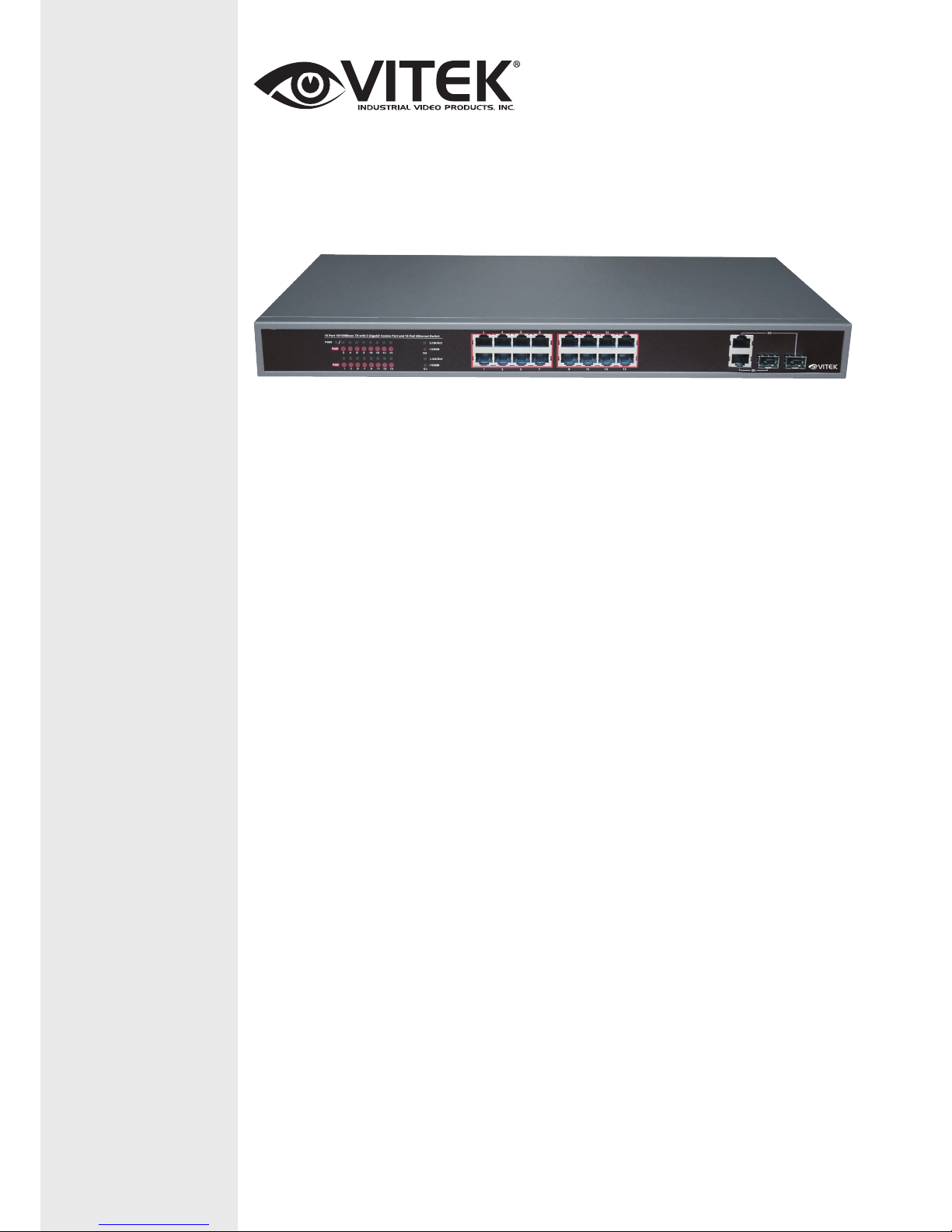
VT-16P250WS
16 Port L2 Web Smart Ethernet
Switch with PoE Injector
• Provides 16 - 10/100Base-TX PoE ports & 2 combo ports (10/100/1000Base-T
or 1000Base-X)
• 250 Watt PoE Power Budget
• Level 2 Managed Switch
• Visual PoE Status via LED
• PoE ON/OFF Control
• PoE Schedule
• PD Alive auto Check
• High back-plane bandwidth 7.2Gbps
• Port mirror and bandwidth control
• IEEE802.3x Flow control
• Conforms to IEEE802.3, IEEE 802.3u, IEEE 802.3ab, IEEE802.3z, IEEE802.3af,
IEEE802.3at
• Supports Port Based VLAN / 802 .1Q Tag VLAN
• Supports IEEE802.3ad Port trunk with LACP
• Supports IEEE 802.1p class of service
• Supports Broadcast storm filter
• Supports DHCP clients
• Web Based Management
• Surge protection for power port and data ports
• Rack Ears Included
• EMI standards complies with FCC, CE class A
FEATURES

VT-16P250WS: 16 Port L2 Web Smart Ethernet PoE Switch
2
Contents
1 Introduction .............................................................................................................................................................. 2
2 Hardware Description .............................................................................................................................................. 2
2.1 Front Panel .................................................................................................................................................... 2
2.2 LED Indicators .............................................................................................................................................. 2
2.3 Rear Panel ..................................................................................................................................................... 3
3 Hardware Installation ............................................................................................................................................... 4
3.1 Package contents ........................................................................................................................................... 4
3.2 Switch Installation ........................................................................................................................................ 4
3.3 Grounding the Switch ................................................................................................................................... 5
3.4 Plugging in the AC Power Cord ................................................................................................................... 5
3.5 Connecting Ethernet Interface ...................................................................................................................... 6
4 Troubleshooting ....................................................................................................................................................... 7
5 Getting Started ......................................................................................................................................................... 8
5.1 Management Options .................................................................................................................................... 8
5.2 Using Web-based Management .................................................................................................................... 8
6 Configuration ........................................................................................................................................................... 9
6.1 Welcome ....................................................................................................................................................... 9
6.2 Administrator ................................................................................................................................................ 9
6.3 Port Management ........................................................................................................................................ 12
6.4 VLAN Setting ............................................................................................................................................. 15
6.5 Per Port Counter .......................................................................................................................................... 16
Per Port Counter -> Port Counter ..................................................................................................................... 16
6.6 QoS Setting ................................................................................................................................................. 16
6.7 Security ....................................................................................................................................................... 18
6.8 Spanning Tree ............................................................................................................................................. 18
6.9 Trunking ...................................................................................................................................................... 20
6.10 DHCP Relay Agent ................................................................................................................................... 21
6.11 Backup/Recovery ...................................................................................................................................... 21
6.12 Miscellaneous ........................................................................................................................................... 22
6.13 SNMP Settings .......................................................................................................................................... 23
6.14 Logout ....................................................................................................................................................... 23
6.15 PoE ............................................................................................................................................................ 24
PoE -> PoE Setting ........................................................................................................................................... 24
VT-16P250WS: 16 Port L2 Web Smart Ethernet PoE Switch
3
1 Introduction
Power-over-Ethernet (PoE) eliminates the need to run DC power to other devices on a wired LAN. Using a
Power-over-Ethernet system, installers need to run only a single Category 5 Ethernet cable that carries both power
and data to each device. This allows greater flexibility in the locating of network devices and, in many cases,
significantly decreases installation costs.
There are two system components in PoE - the PSE (Power Sourcing Equipment) and the PD (Powered Device).
The IEEE 802.3af/at specification defines PSE as a device that inserts power onto an Ethernet cable. The PSE
may be located at the switch (End-span configuration). or it may be a separate device located between the switch
and the PD (Mid-span configuration). The PD is the natural termination of this link, receiving the power, and
could be an IP phone, a WLAN access point, or any other IP device that requires power. The current is transmitted
over two of the four twisted pairs of wires in a Category-5 cable.
Power-over-Ethernet follows the IEEE 802.3af/at specification and is completely compatible with existing
Ethernet switches and networked devices. Because the Power Sourcing Equipment (PSE) tests whether a
networked device is PoE-capable, power is never transmitted unless a Powered Device is at the other end of the
cable. It also continues to monitor the channel. If the Powered Device does not draw a minimum current, because
it has been unplugged or physically turned off, the PSE shuts down the power to that port. Optionally, the standard
permits Powered Devices to signal to the PSEs exactly how much power they need.
The PoE switch is a multi-port fast Ethernet switch that can be used to build high-performance switched
workgroup networks. This switch is a store-and-forward device that offers low latency for high-speed networking.
It also features a ‘store-and-forward switching’ scheme that allows the switch to auto-learn and store source
addresses in a 8K-entry MAC address table. The switch is targeted at workgroup, department or backbone
computing environments.
2 Hardware Description
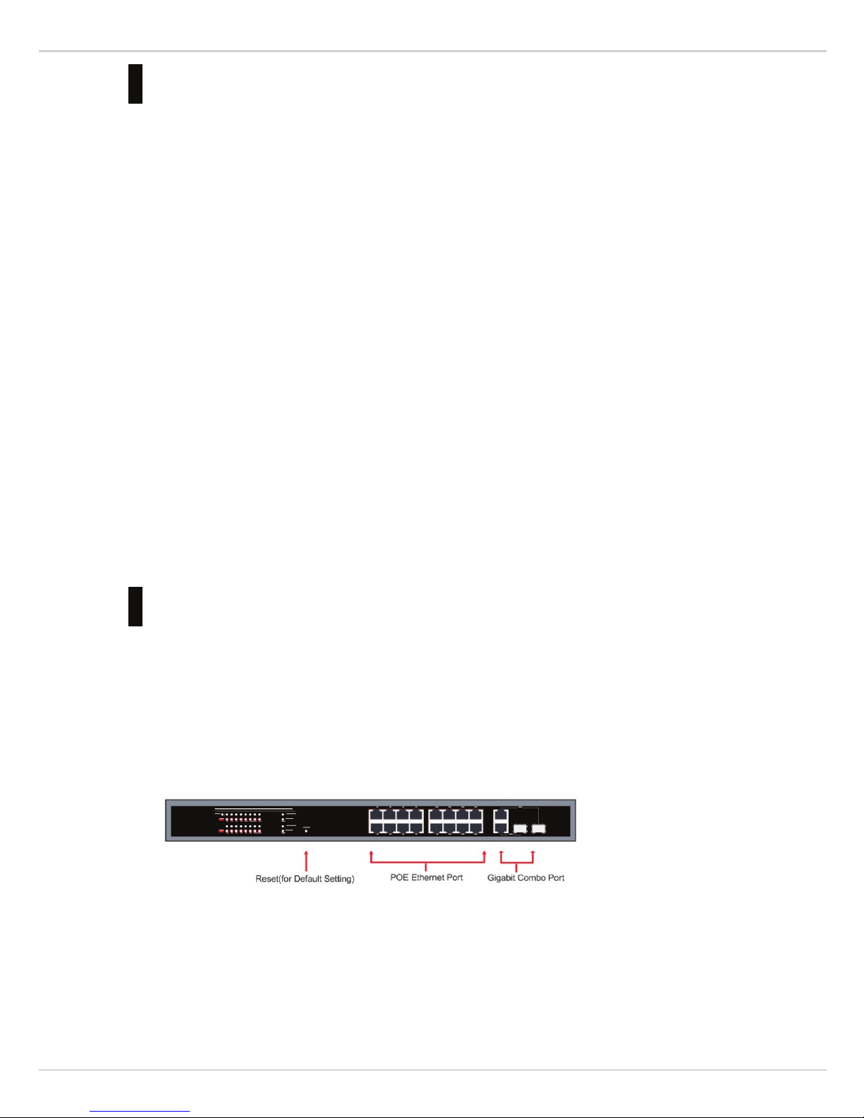
2.1 Front Panel
The front panel consists of LED indications, reset button and 16 x10/100 PoE ports + 2x10/100/1000 Uplink pots.
2.2 LED Indicators
Power LED: The Power LED lights up when the switch is connected to a power source.
Link/Act LED:
Green (for megabit ports): Indicates that the port is running at 100M.
VT-16P250WS: 16 Port L2 Web Smart Ethernet PoE Switch
4
Green (for gigabit ports): Indicates that the port is running at 1000M.
Blinking: Indicates that the switch is either sending or receiving data to the port.
Light off: No link.
PoE LED:
Green: Indicates the PoE powered device (PD) is connected and the port supplies power successfully.
Light off: Indicates no powered device (PD) connected.
Reset: By pressing the Reset button for 5 seconds the switch will change back to the default configuration and all
changes will be lost.
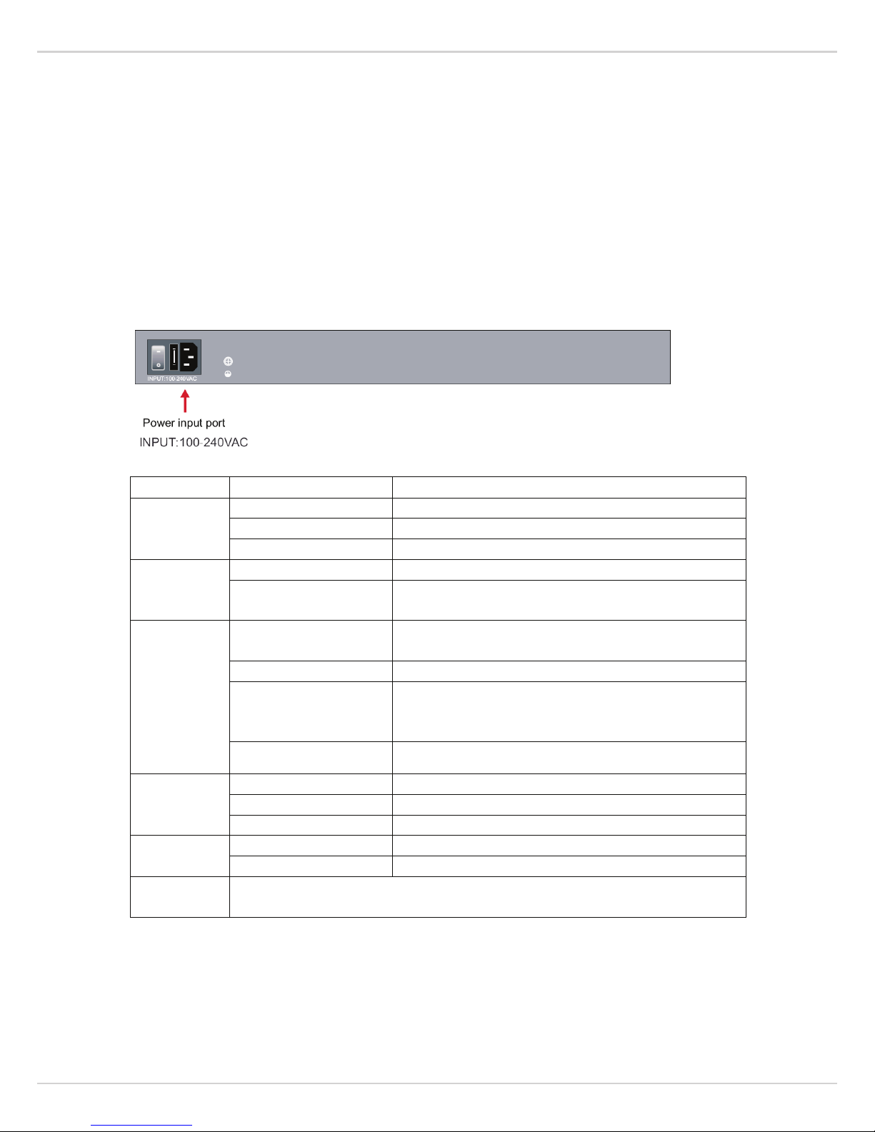
2.3 Rear Panel
The rear panel view of the switch consists of an AC power connector, Power Switch and Fuse.
2.4 Specification
Item Description
Power
Power Supply Built-in power supply
Voltage Range AC100~240V
Consumption 250W for 16PoE 370W for 24PoE
Ethernet
Speed 1~16 Port:10/100Mbps G1~G2:Gigabit Combo
Transmission Distance
100Meter (328ft) for RJ 45
2Km 20Km for SFP Port The optical module is optional
Network Switch
Ethernet Standard
IEEE 802.3/802.3u /802.3 ab/802.3af /at
Power supply pin: 45.78
Switching capacity 16+2G for 7.2G
Transfer Rate
14,880 pps for 10Mbps
148,800 pps for 100Mbps
148,8000 pps for 1000Mbps
MACAddress 4K MAC address table
Working
Environment
Working Temperature 32°F ~ 104°F / 0℃ ~ 40℃
Storage Temperature -40°F ~ 158°F / -40℃ ~ 70℃
Humidity Non Condensing 0~85%
Mechanical
Dimension L*W*H 17.3”*7.9”*1.75” / 440*200*44mm
Color Gray
W
eb-smart
Support via the browser on the port (Vlan, Mirroring, etc.)
PoE part of the current power display, Scheduling, Autocheck.

VT-16P250WS: 16 Port L2 Web Smart Ethernet PoE Switch
5
3 Hardware Installation
3.1 Package contents
Package contents include the following:
n PoE Switch: 16x10/100 PoE ports with 2x10/100/1000 combo ports Ethernet Switch
n AC power cord
n Two (2) rack-mount ears and Six (6) screws
n Four (4) adhesive-backed rubber feet
n User’s manual
IMPORTANT: If any piece is missing or damaged, please contact your local dealer or reseller for service.
3.2 Switch Installation
Desktop or Shelf Installation
When installing the switch on a desktop or shelf, the rubber feet included with the device must be attached on the
bottom at each corner of the device’s base. Allow enough ventilation space between the device and the objects
around it.
Note: Do not press on the switch. Any pressure more than 9lbs may cause damage to switch.
Rack Installation
The switch can be mounted in an EIA standard size 19-inch rack; which can be placed in a wiring closet with
other equipment. To install, attach the mounting brackets to the switch’s side panels (one on each side) and secure
them with the screws provided.
Then, use the screws provided with the equipment rack to mount the switch in the rack.
Please be aware of following safety instructions when installing:
n Elevated Operating Ambient - If installed in a closed or multi-unit rack assembly, the operating ambient
temperature of the rack environment may be greater than room temperature. Therefore, consideration should
be given to installing the equipment in an environment compatible with the maximum ambient temperature
(Tma) specified by the manufacturer.

VT-16P250WS: 16 Port L2 Web Smart Ethernet PoE Switch
6
n Reduced Air Flow - Installation of the equipment in a rack should be such that the amount of air flow
required for safe operation of the equipment is not compromised.
n Mechanical Loading - Mounting of the equipment in the rack should be such that a hazardous condition is
not achieved due to uneven mechanical loading.
n Circuit Overloading - Consideration should be given to the connection of the equipment to the supply circuit
and the effect that overloading of the circuits might have on over current protection and supply wiring.
Appropriate consideration of equipment nameplate ratings should be used when addressing this concern.
n Reliable Grounding - Reliable Grounding of rack-mounted equipment should be maintained. Particular
attention should be given to supply connections other than direct connections to the branch circuit (e.g. use of
power strips)."
3.3 Grounding the Switch
The section describes how to connect the switch to ground. You must complete this procedure before powering
your switch.
Required Tools and Equipment
l Ground screws: One M4 x 6mm (metric) pan-head screw
l Ground cable: The grounding cable should be sized according to local and national installation requirements.
Depending on the power supply and system, a 6 to 12 AWG copper conductor is required for U.S installation.
Commercially available 6 AWG wire is recommended. T
he length of the cable depends on the proximity of
the switch to proper grounding facilities.
l A screwdriver
The following steps let you connect the switch to a protective ground:
Step 1: Verify if the system power is off.
Step 2: Use the ground cable to place the #8 terminal lug ring on top of the ground-screw opening, as
seen in the figure below.
Step 3: Insert the ground screw into the ground-screw opening.
Step 4: Using a screwdriver, tighten the ground screw to secure the ground cable to the switch.
Step 5: Attach the terminal lug ring at the other end of the grounding cable to an appropriate grounding
stud or bolt on rack where the switch is installed.
Step 6: Verify if the connections at the ground connector on the switch and the rack are securely
attached.
3.4 Plugging in the AC Power Cord
Users may now connect the AC power cord into the rear of the switch and to an electrical outlet (preferably one
that is grounded and surge protected).

VT-16P250WS: 16 Port L2 Web Smart Ethernet PoE Switch
7
Power Failure
As a precaution, the switch should be unplugged in case of power failure. When power is resumed, plug the
switch back in.
3.5 Connecting Ethernet Interface
Use switch’s UTP to connect to other Ethernet terminals. Refer to the following chart:
UTP port explanation for Fast Ethernet is shown as follows:
Pin NO.
Description
Name
Note
1 Data transmission positive TPTXD+ Output
2 Data transmission negative TPTXD- Output
3 Data receive positive TPRXD+ Input
6 Data receive negative TPRXD- Input
UTP port explanation for Gigabit Ethernet is shown as follows:
Pin NO. Description Name Note
1 Data transmission positive TPTXD1+ Output
2 Data transmission negative TPTXD1- Output
3 Data receive positive TPRXD2+ Input
6 Data receive negative TPRXD2- Input
4 Data Bi-directional positive BI_D3+ Bidirectional
5 Data Bi-directional negative BI_D3- Bidirectional
7 Data Bi-directional positive BI_D4+ Bidirectional
8 Data Bi-directional negative BI_D4- Bidirectional
Cable connection and colors follow the regulations in EIA/TIA 568A as follows:
VT-16P250WS: 16 Port L2 Web Smart Ethernet PoE Switch
8
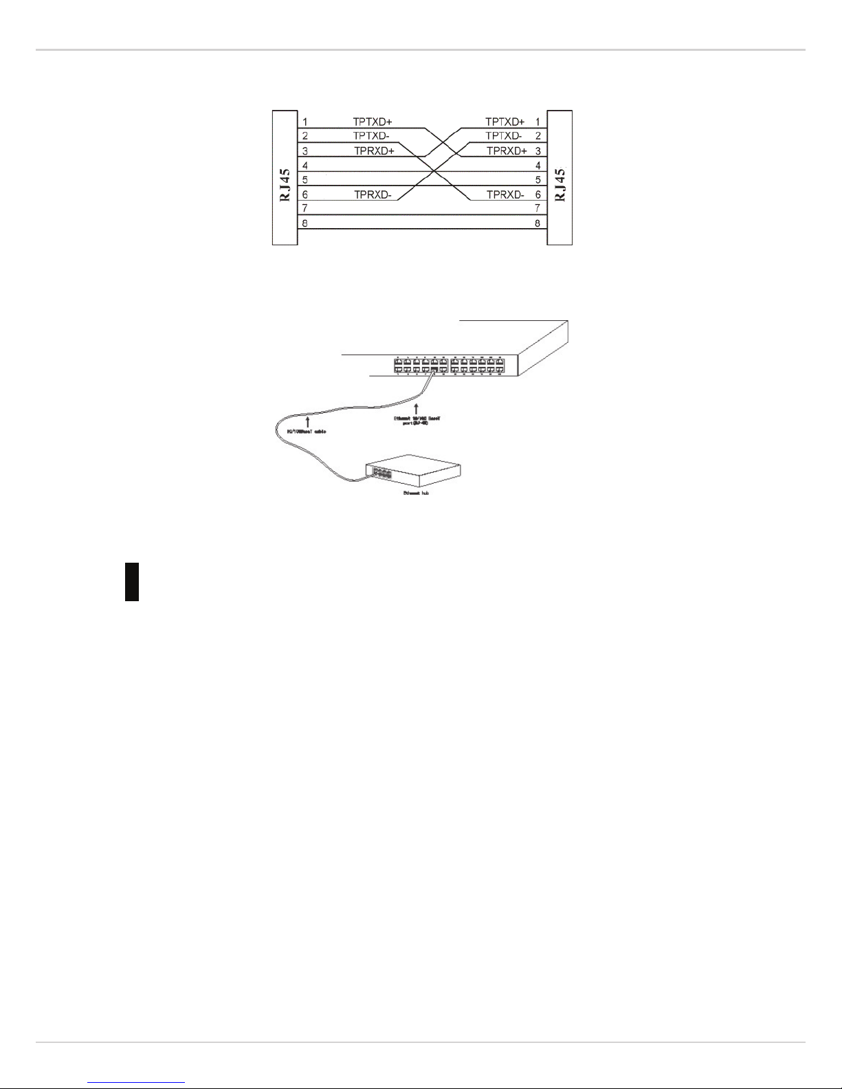
Cable connection and colors follow the regulation in EIA/TIA 568B as follows:
Choose the connection which best fits the connection between switch and other Ethernet terminal. 10/100Base-TX
port and other Ethernet terminal connection is shown as follows:
4 Troubleshooting
This section is intended to help solve the most common issues with the PoE Switch
Incorrect connections
Every port on this switch can automatically detect either straight or crossover cables when you link it with other
Ethernet devices but other devices may demand a specific cable type (depending on the device). Choose the
appropriate cable to connect between the units. The RJ-45 connector should use correct UTP or STP cable,
10/100Mbps port use 2-pairs twisted cable. If the RJ-45 connector is not correctly pinned then the link will fail.
Faulty or loose cables
Look for loose or obviously faulty connections. If they appear to be OK, make sure the connections are snug. If
that does not correct the problem, try a different cable.
Non-standard cables
Non-standard and miss wired cables may cause numerous network collisions and other network problems, and can
seriously impair network performance. A cable tester is the recommended tool for network installation.
RJ-45 ports: Use unshielded twisted-pair (UTP) or shield twisted-pair (STP) cable for RJ-45 connections: 100Ω
Category 3, 4 or 5 cables for 10Mbps connections, 100Ω Category 5 cable for 100Mpbs connections, or 100Ω
Category 5e/above cable for 1000Mbps connections. Also be sure that length of any twisted-pair connection does
not exceed 100 meters (328 feet). We suggest using Category 5e cable when connection to power a device.

VT-16P250WS: 16 Port L2 Web Smart Ethernet PoE Switch
9
Improper Network Topologies
It is important to make sure that you have a valid network topology. Common topology faults include excessive
cable length and too many repeaters (hubs) between end nodes. In addition, you should make sure that your
network topology contains no data path loops. Between any two ends nodes, there should be only one active
cabling path at any time. Data path loops will cause broadcast storms that will severely impact your network
performance.
Diagnosing LED Indicators
To assist in identifying problems, the switch can be easily monitored through panel indicators, which describe
common problems the user may encounter and where the user can find possible solutions. If the LED display
detection isn’t correct, please unplug then plug in the cable again.
If the power indicator does not light when the power cord in plugged in, you may have a problem with the power
outlet or power connections, power losses, or surges at power outlet. If the problem still cannot be resolved, please
contact the local dealer for assistance.
5 Getting Started
This chapter introduces the management interface of the switch.
5.1 Management Options
The Switch can be managed through any port on the device by using the Web-based Management
Each switch must be assigned its own IP Address, which is used for communication with Web-Based
Management. The PC’s IP address should be in the same range as the switch. Each switch can allow only one user
to access the Web-Based Management at a time.
Please refer to the following installation instructions for the Web-based Management.
5.2 Using Web-based Management
After a successful physical installation, you can configure the switch, monitor the network status, and display
statistics using a web browser.
Connecting to the Switch
You will need the following equipment to begin the web configuration of your device:
n A PC with a RJ-45 Ethernet connection
n A standard Ethernet cable
Connect the Ethernet cable to any of the ports on the front panel of the switch and to the Ethernet port on the PC.
Login Web-based Management
In order to login and configure the switch via an Ethernet connection, the PC must have an IP address in the same
subnet as the switch. For example, if the switch has an IP address of 192.168.2.1, the PC should have an IP
address of 192.168.2.x (where x is a number between 2 ~ 254), and a subnet mask of 255.255.255.0. Open the
 Loading...