

Vision Fitness ST730 User Manual

ST730
MULTI-LAT
Assembly &
Owner’s Guide

2

3
ASSEMBLY GUIDE . . . . . . . . . . . . . . . . 4
HARDWARE BAGS . . . . . . . . . . . . . . . . 6
STEP 1: ORANGE BAG . . . . . . . . . . . . . 9
STEP 2: BLUE BAG . . . . . . . . . . . . . . . 10
STEP 3: PINK BAG . . . . . . . . . . . . . . . 11
STEP 4: GREEN BAG . . . . . . . . . . . . . . 12
STEP 5: CABLE #1 . . . . . . . . . . . . . . . 13
STEP 6: CABLE #2 . . . . . . . . . . . . . . . 14
STEP 7: BLACK BAG . . . . . . . . . . . . . . 15
STEP 8: YELLOW BAG . . . . . . . . . . . . 16
ASSEMBLY GUIDE OWNER’S GUIDE
RESISTANCE TRAINING BENEFITS
& TIPS, WORKOUT VARIATIONS . . . . . . 18
TRAINING PROGRAMS . . . . . . . . . . . . 19
STRETCHING . . . . . . . . . . . . . . . . . . . 20
MAINTENANCE SCHEDULE . . . . . . . . . . 22
COMMERCIAL WARRANTY . . . . . . . . . . 23
WORKOUT LOGS . . . . . . . . . . . . . . . . 24
Table of Contents

4
To avoid possible damage to this Multi-Lat, please follow these assembly steps in the correct order. Before
proceeding, find your new Multi-Lat serial number located on the side of the main floor support (AT1), and enter here:
Refer to this number when calling for service, and enter this serial number on your Warranty Card and in your
own records. Be sure to read your Owner’s Guide before using your new Multi-Lat.
If any parts, hardware or tools are missing, please call 1.800.335.4348, Extension 12
NOT E: During assembly, it is recommended to ensure that all bolts are in place and partially threaded before completely
tightening any one bolt. During assembly steps 1 thru 4, do not completely tighten any bolts until completion of Step 4.
Assembly &
Owner’s Guide
ST730
MULTI-LAT
5
2
STEP
1
STEP
3
STEP
4
STEP
7
STEP
5
STEP
8
STEP
6
STEP
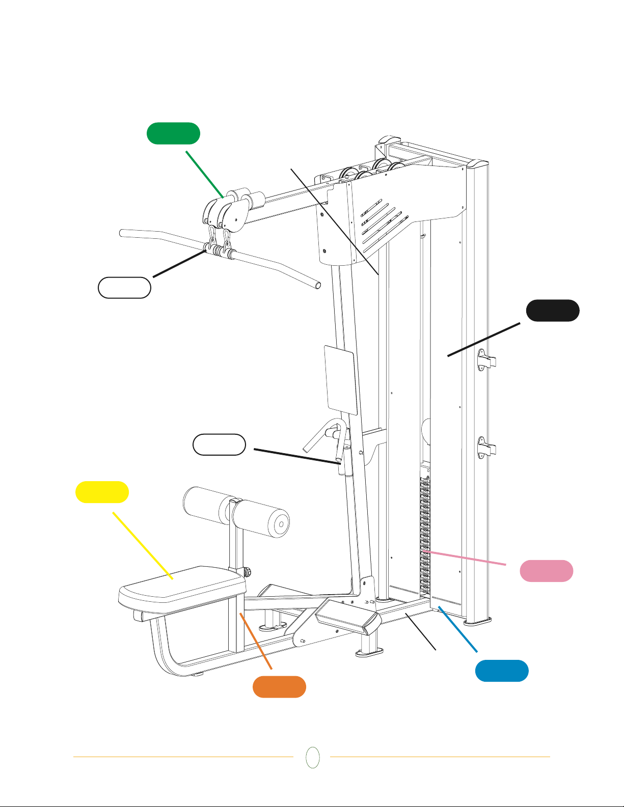
General Warning
Decal
Serial #
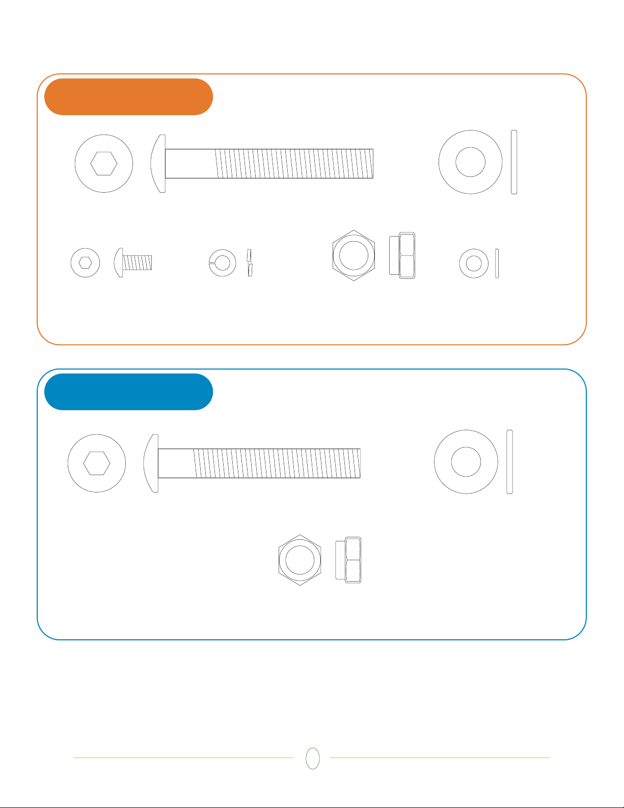
ORANGE BAG
6
HARDWARE INCLUDED
BLUE BAG
10.2 x 22 x 2
Flat Washer
Quantity: 14
M10 Nylon Nut
Quantity: 7
M10 x 72 Bolt
Quantity: 7
M5 x 10 Bolt
Quantity: 4
5.1 x 9.3 x 1.3
Lock Washer
Quantity: 4
10.2 x 22 x 2
Flat Washer
Quantity: 4
M10 Nylon Nut
Quantity: 2
M10 x 70 Bolt
Quantity: 2
5.3 x 10 x 1.0
Flat Washer
Quantity: 4
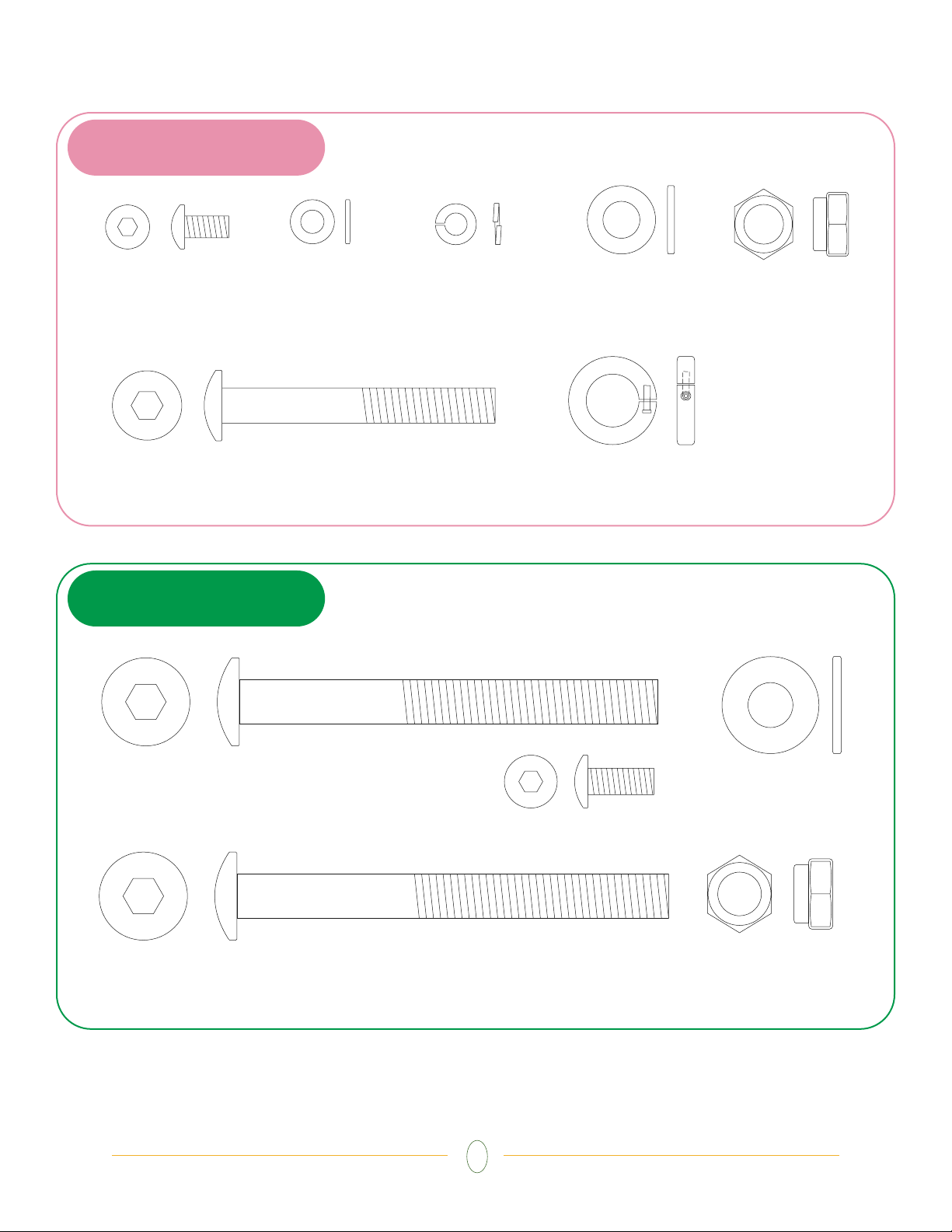
GREEN BAG
7
HARDWARE INCLUDED
PINK BAG
M5 x 10 Bolt
Quantity: 20
5.3 x 10 x 1.0
Flat Washer
Quantity: 20
5.1 x 9.3 x 1.3
Lock Washer
Quantity: 20
M8 x 62 Bolt
Quantity: 2
8.4 x 15.5 x 1.6
Flat Washer
Quantity: 4
M8 Nylon Nut
Quantity: 2
Stopper Ring
(illustration not to scale)
Quantity: 1
10.2 x 22 x 2
Flat Washer
Quantity: 12
M10 Nylon Nut
Quantity: 6
M10 x 95 Bolt
Quantity: 2
M10 x 98 Bolt
Quantity: 4
M6 x 15 Bolt
Quantity: 4
8
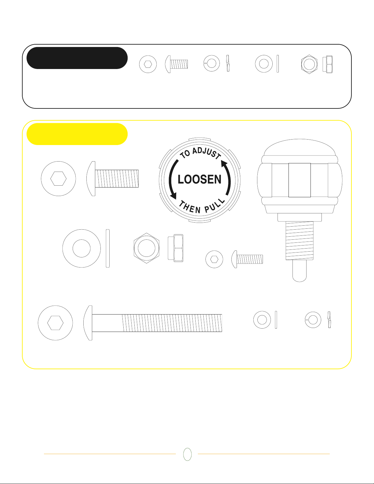
HARDWARE INCLUDED
BLACK BAG
YELLOW BAG
M5 x 10 Bolt
Quantity: 36
5.3 x 10 x 1
Flat Washer
Quantity: 20
10.2 x 22 x 2
Flat Washer
Quantity: 2
M10 x 25 Bolt
Quantity: 6
Pull Pin
Quantity: 1
5.3 x 10 x 1
Flat Washer
Quantity: 4
5.1 x 9.3 x 1.3
Lock Washer
Quantity: 4
M5 x 15 Bolt
Quantity: 4
M10 x 75 Bolt
Quantity: 1
M10 Nylon Nut
Quantity: 1
M5 Nylon Nut
Quantity: 2
5.1 x 9.3 x 1.3
Lock Washer
Quantity: 4
AG1
AT2
AT3
AT1
C05
9
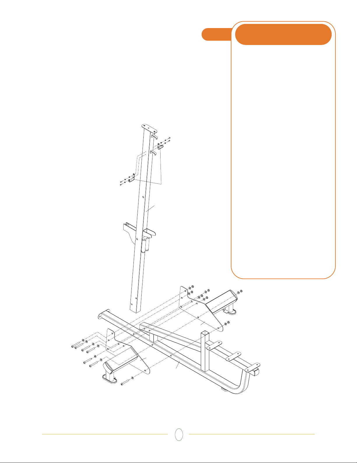
1
STEP
•
NOTE: It is recommended that all
bolts in Steps 1 thru 4 are loosely
fastened. Tighten all hardware at
the conclusion of Step 4
• With the flat side down, place the left
foot support (AT2) up against the main
floor support (AT1), aligning the three
holes along bottom of both pieces. Place
three bolts (M10x72) and three flat washers
(10.2x22x2) through left foot support and
main floor support. Take right foot support
(AT3) and slide onto bolts sticking out
other side of main floor support (AT1).
Place a flat washer (10.2x22x2) on each
bolt, and partially thread one nylon nut
(M10) on each bolt. Do not place bolts
through other remaining holes until next step!
• Stand the upright frame (AG1), placing
the end with four holes in the broad side,
into the remaining slot between the left
and right foot supports. Make sure the
rollers on the upright are facing the seat
support. Use four bolts (M10x72), eight
flat washers (10.2x22x2), and four nylon
nuts (M10) to secure the upright.
• Attach a bracket (C05) to each side of
the upright frame (AG1) with two bolts
(M5x10), two lock washers (5.1x9.3x1.3),
and two flat washers (5.3x10x1.0).
ORANGE BAG
AG1
C05
AT3
AT2
AT1
 Loading...