

Page 1
Page 2
NAVIGATION INSTRUCTIONS
Exit
Contents
The symbols in the left-hand margin of each page of the manual will enable you to carry out the following functions:
The buttons in text below do not function. They are for illustrative purposes only.
Click on this button to display the Contents page.
Back one page.
Forward one page.
Back button.
Forward button.
Click this button to print some or all of the document (specic pages can be chosen).
Click this button to exit the user guide.
Press the Esc key to display normal Acrobat© Controls.
Page 3
PREFACE
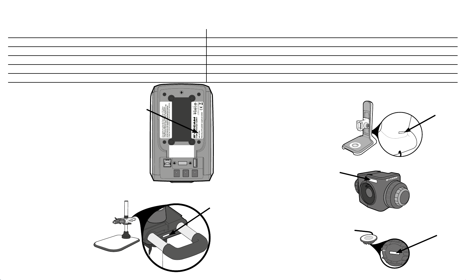
System serial numbers
Unit type Serial number
EVO Cam II
Multi-axis stand
Ergo stand
Focus assembly
Transmitted substage illumination module (option)
EVO Cam II
On the rear of the unit.
Multi-axis stand
On the rear of the stand mechanism.
S/N
S/N
Ergo stand
At the base of the column at the back.
Focus assembly
S/N
On the rear of the unit.
Transmitted substage illumination module (option)
On the underside of the module.
S/N
S/N
Page 4

Copyright
Disclaimer
Copyright © 2018 Vision Engineering Ltd., Galileo Drive, Send Road, Send, Woking,
Surrey GU23 7ER, UK All Rights Reserved.
Mantis® (1532468), Lynx® (3672061) and Dynascope® (915579) are registered
trademarks of Vision Engineering Ltd. The use of our trademarks is strictly controlled
and monitored and any unauthorised use is forbidden.
Copyright in this document is owned by Vision Engineering Ltd. Any person is hereby
authorised to view, copy, print and distribute this document subject to the following
conditions:
The document may be used for informational purposes only
The document may be used for non-commercial purposes only
Any copy of this document or portion thereof must include this copyright notice
Revision 1.0, published February 2018 by:
Vision Engineering Ltd.
Galileo Drive
Send Road, Send
Woking, Surrey, GU23 7ER, UK
www.visioneng.com
This document is provided “as is” without any warranty of any kind, either express
or implied, statutory or otherwise; without limiting the foregoing, the warranties of
satisfactory quality, tness for a particular purpose or non-infringement are expressly
excluded and under no circumstances will Vision Engineering Ltd. be liable for direct
or indirect loss or damage of any kind, including loss of prot, revenue, goodwill
or anticipated savings. All such warranties are hereby excluded to the fullest extent
permitted by law.
We have compiled the texts and illustrations as accurately as possible. However, Vision
Engineering Ltd. will not be responsible for the accuracy of the information contained
in this document, which is used at your own risk and should not be relied upon. The
information included in this manual may be changed without prior notice.
Page 5

Contents
Contents
PREFACE 3
ASSEMBLY 10
MAINTENANCE 27
System serial numbers 3
EVO Cam II 3
Multi-axis stand 3
Ergo stand 3
Focus assembly 3
Transmitted substage illumination module (option) 3
Copyright 4
Disclaimer 4
General 6
Safety 6
Cleaning 6
Servicing 6
Symbols used 6
Warning! 6
Warning of electrical shock hazard 6
Important information 6
Health & safety 6
Electrical safety 6
Illumination safety 6
Environmental considerations 6
Operator wellbeing 6
Compliance statements 6
SYSTEM DIAGRAM 7
Transmitted substage illuminator (option) 10
Stand mounts 11
Ergo stand 11
Polarisation lter (option) 11
Multi-axis stand 11
Objective lens 12
Cabling 12
OPERATION 13
Quick start 13
Control functions 14
Power on/off 14
Illumination control 14
Image capture 14
Magnication 15
Magnication level OSD (On Screen Display) 15
Overview 15
Main menu options 16
Exposure options 16
Focus options 18
Calibration 19
Measurement 20
Presets and hotkeys 21
Settings 21
Troubleshooting 27
Taking care of your EVO Cam II 27
FIRMWARE UPGRADE 27
Firmware upgrade 27
SPECIFICATION 28
SERVICING 29
Service record 29
WARRANTY 30
Sub-assemblies 7
Optical data 8
Stand options 9
Using the remote keypad (optional) 26
Front Panel Lock 26
Changing the camera objective lens 26
Using the Video Out via USB 3. 26
Page 6
General
Safety
Before using your system for the rst time, please read the
Health & safety section of the user guide.
Ensure that:
Your system and accessories are operated, maintained
and repaired by authorised and trained personnel only.
All operators have read, understood and observe the user
manual, in particular the safety regulations.
Cleaning
Disconnect your system from the electrical source before
cleaning.
Do not use any unsuitable cleaning agents, chemicals or
techniques for cleaning.
Never use chemicals to clean coloured surfaces or
accessories with rubberised parts.
Use a specialist lens cloth to clean optical surfaces.
Servicing
Repairs may only be carried out by Vision Engineeringtrained service personnel. Only original Vision Engineering
spare parts may be used.
Symbols used
Warning!
A potential risk of danger exists. Failure to comply can
cause i) a hazard to personnel; ii) instrument malfunction
and damage. Please consult the operating instructions
provided with the product.
Warning of electrical shock hazard
This symbol indicates the presence of electric shock hazards.
Please consult the operating instructions provided with the
product.
Important information
This symbol indicates important information. Please
carefully follow the instructions or guidelines.
Health & safety
Unauthorised alterations to the instrument or
non-compliant use shall invalidate all rights to any
warranty claims.
Electrical safety
Disconnect your system from the electrical source before
undertaking any maintenance.
Avoid using any form of liquid near the system.
Do not operate your system with wet hands.
Illumination safety
Do not look directly at the illuminated LED’s. This may
cause damage to the eyesight.
Environmental considerations
Avoid large temperature uctuations, direct sunlight and
vibrations.
Ensure electrical components are at least 10cm from walls
and combustible materials.
Position the system on a rm, rigid and level table.
The equipment should be positioned so that access to the
electrical input connector is always available.
Avoid positioning your system where bright reections
may affect the image.
Operator wellbeing
The advanced ergonomic design and construction of
Vision Engineering products are intended to deliver
superior ergonomic performance, reducing the exertion
of the user to a minimum. Depending on the duration
of uninterrupted work, appropriate measures should
be taken to sustain optimal operator performance.
This could include: Optimal arrangement of workplace;
Variation in task activity; Training of personnel on
workplace ergonomics and general health and safety
principles.
It is important to set-up and optimise your working
environment correctly in order to obtain maximum benet
from the advanced ergonomic design of your system. For
more information visit: www.visioneng.com/ergonomics
Compliance statements
Vision Engineering and its products conforms to the requirements
of the EC Directives on Waste Electrical and Electronic Equipment
(WEEE) and Restriction of Hazardous Substances (RoHS).
All Vision Engineering products conform to the CE mark,
demonstrating that each product meets the requirements
of the applicable EC directives. Where applicable, other
characteristics of the CE directive are implied such as
essential health and safety requirements from all the
directives that applies to its product, including low voltage
directive and the EMC directive.
Page 7
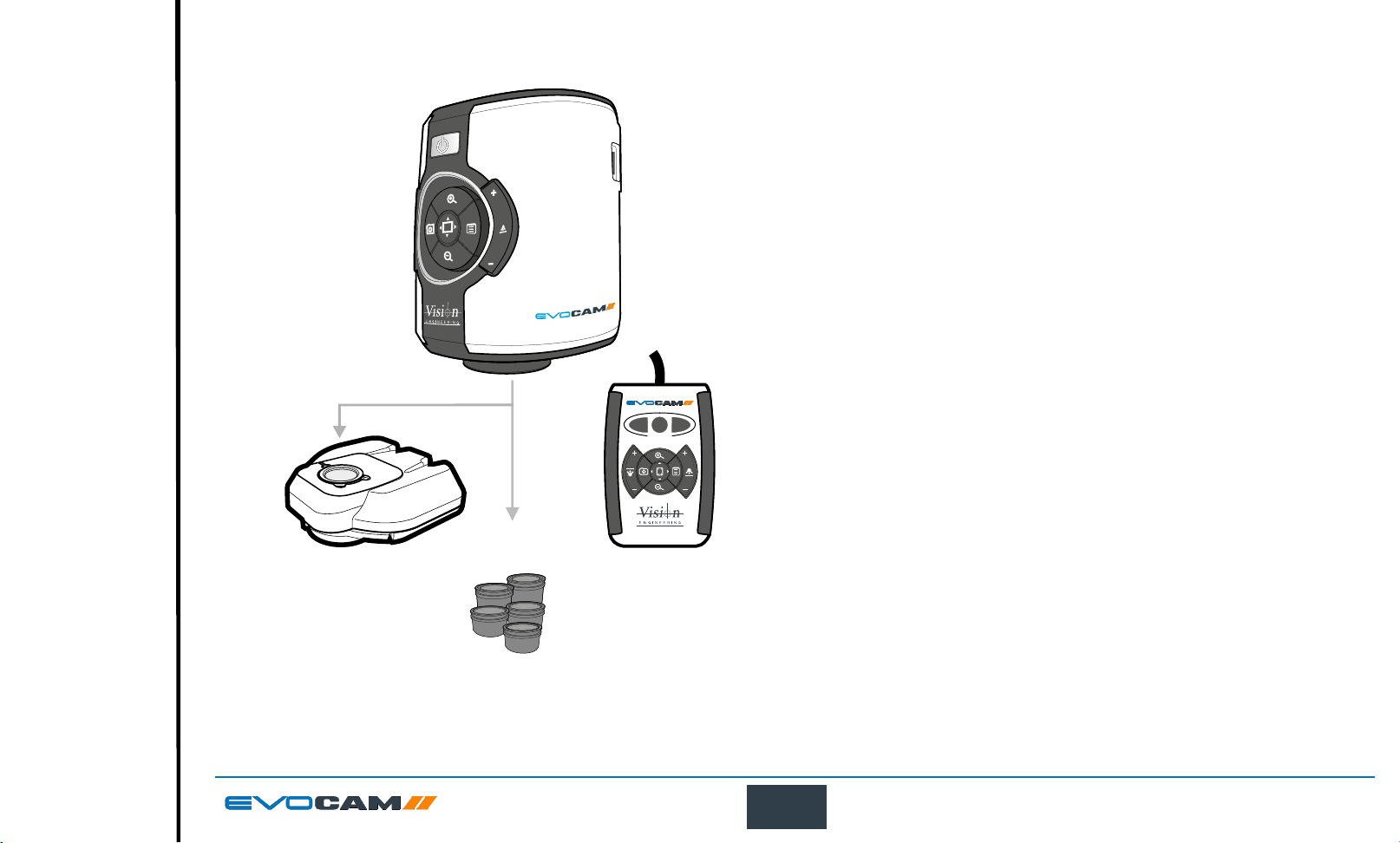
SYSTEM DIAGRAM
360° r
ables)
Exit
Contents
Preface
Assembly
Operation
Maintenance
Specication
System Diagram
Start page
Sub-assemblies
EVO Cam II
ECH 005
P3
P1
P2
PRESET
Standard box contents:
EVO Cam II camera unit
Power supply unit
Plug cord
HDMI cable
USB3 cable
Lens cloth
2mm HEX key
otating viewer
(optional)
EVR066
Remote Keypad
(optional)
ECX155
Objective lenses
(see Optical data t
7
SYSTEM DIAGRAM
Page 8
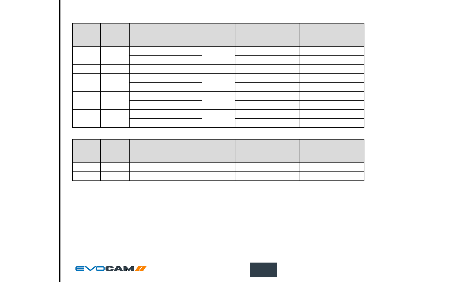
Optical data
Exit
Contents
Preface
Assembly
Operation
Maintenance
Specication
System Diagram
Start page
Objective
lens
number
0.45x ECL001
Part
Magnication
zoom range*
Full eld: 2.27x – 68.04x
Optimal: 3.78x – 68.04x 142.6mm / 82.6mm 7.8mm / 4.2mm
Working
distance
160mm
Field of view
at min. zoom
(width / height)
241.0mm / 134.0mm 7.8mm / 4.2mm
Field of view
at max. zoom
(width / height)
0.62x ECL002 Full eld: 3.12x – 93.74x 106mm 173.1mm / 96.8mm 5.5mm / 3.1mm
1.0x ECL003
1.5x ECL150
2.0x ECL200
Full eld: 5.04x – 151.2x
Optimal: 12.56x – 151.2x 40.2mm / 23.1mm 3.5mm / 2.0mm
Full eld: 7.56x – 226.8x
Optimal: 16.38x – 226.8x 28.5mm / 17.0mm 2.3mm / 1.2mm
Full eld: 10.08x – 302.4x
Optimal: 23.18x – 302.4x 20.5mm / 12.5mm 1.5mm / 1.0mm
85mm
43mm
29mm
88.0mm / 57.0mm 3.5mm / 2.0mm
45.0mm / 36.0mm 2.3mm / 1.2mm
37.0mm / 27.0mm 1.5mm / 1.0mm
* with 24” monitor
Objective
lens
Part
number
Magnication
zoom range*
Working
distance
Field of view
at min. zoom
(width / height)
Field of view
at max. zoom
(width / height)
4 dioptre ECL040 Full eld: 1.71x – 51.41x 245mm 293mm / 171mm 10mm / 5.5mm
5 dioptre ECL050 Full eld: 2.12x – 65.5x 197mm 232mm / 135mm 8mm / 4.5mm
* with 24” monitor
8
SYSTEM DIAGRAM
Page 9
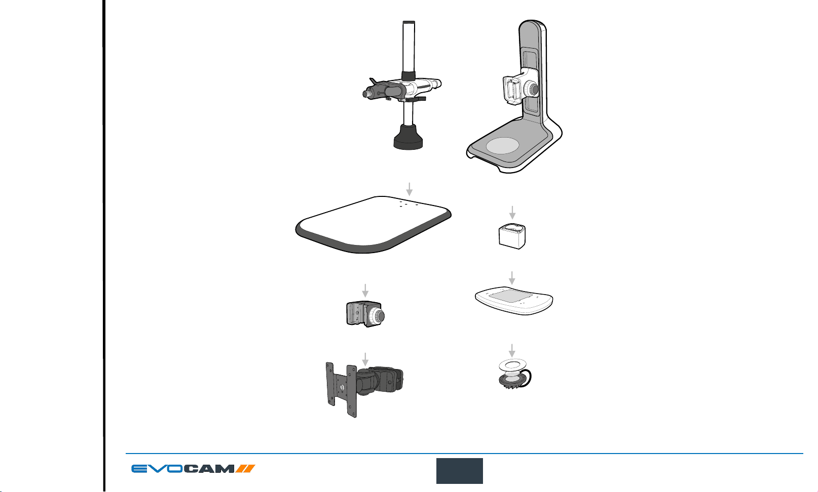
Stand options
Exit
Contents
Preface
Assembly
Operation
Maintenance
Specication
System Diagram
Start page
Multi-axis stand
column and arm
EVB021
Ergo stand
with focus
EVB010
Other stands are also available.
Multi-axis stand
base board
Focus assembly
EVB022
EVF111
Monitor mount
EVB092
75mm Riser Block
EVB093
Multi
-directional
floating stage
EVS120
Transmitted substage illumination
EVS012
9
SYSTEM DIAGRAM
Page 10
ASSEMBLY
Exit
Contents
Preface
Assembly
Operation
Maintenance
Specication
System Diagram
Start page
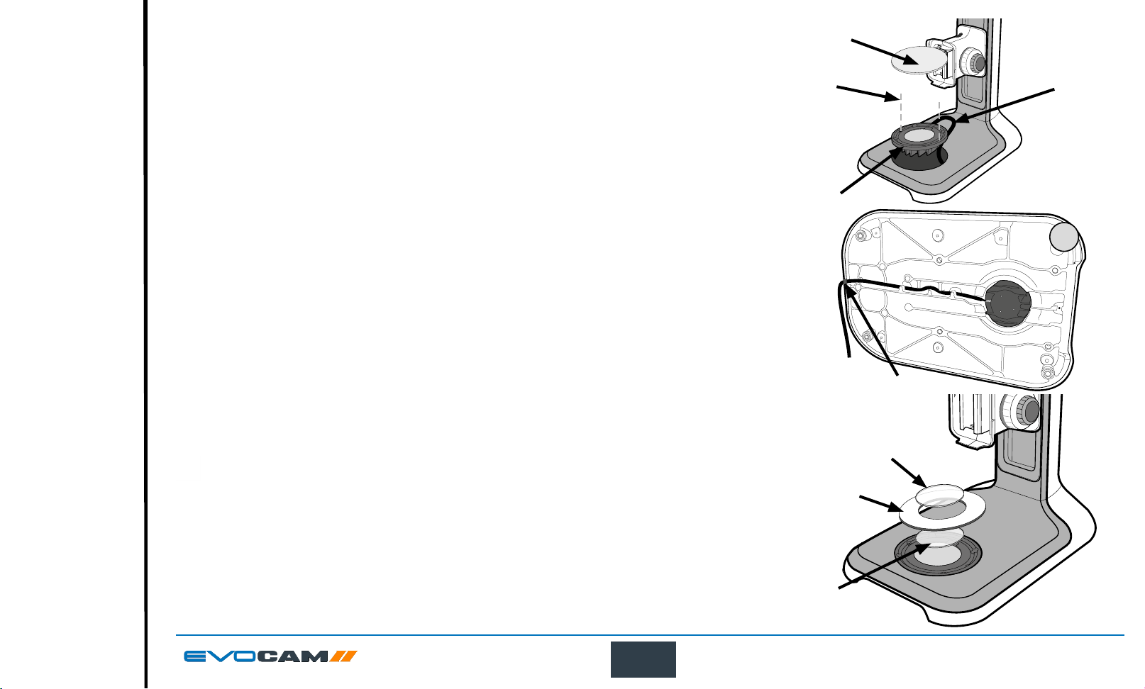
Transmitted substage illuminator (option)
u
` Remove the stage cover plate u and thread the lead v through the stand base.
` Locate the illuminator
` Carefully lay the Ergo stand on to its side and thread the lead through the base as shown.
` Push the cable grommet
` Turn the Ergo stand upright and replace the illuminator diffuser
` Once EVO Cam II is installed on the stand (see page 11) connect the sub-stage power cable to the EVO Cam II.
If assembling the optional glare reducing lter, this needs to be placed between the diffuser and
the surround.
into the stage base and secure it with the 2 screws x.
w
into the stand.
y
shiny side up, surround { and glass |.
z
x
w
v
y
|
{
10
z
ASSEMBLY
Page 11
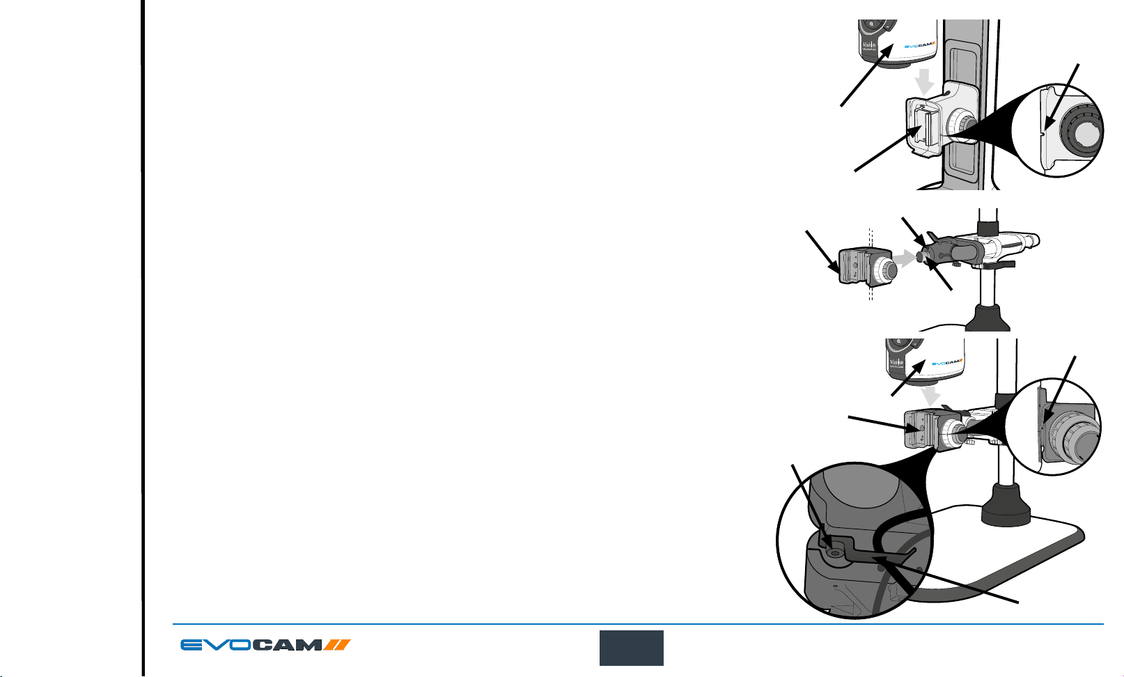
Stand mounts
Exit
Contents
Preface
Assembly
Operation
Maintenance
Specication
System Diagram
Start page
Ergo stand
` Locate EVO Cam II u on to the stand’s dovetail interface v.
` Tighten securing grub screw
with HEX key provided
w
Polarisation lter (option)
Please contact Vision Engineering to have polariser tted into the unit by an authorised engineer.
Multi-axis stand
` Place focus assembly u on the mounting post v so that the locator pin is located in the locator
pin recess w.
To change the camera rotation, remove the locator pin from the focus assembly before attaching
it to the mounting post and attach the focus assembly in the desired orientation.
Take care when mounting EVO Cam II.
` Ensure the mounting plate is perpendicular to the base or work bench. Tighten the 2x grub screws x
at the top of the focus assembly and the 2x grub screws y at the bottom of the focus assembly.
` Locate EVO Cam II
` Tighten securing grub screw
on to the stand’s dovetail interface v.
u
with HEX key provided
w
y
` Secure the cable retaining clip
provided. The clip can be secured to the left or right side.
under the knuckle of the multi-axis stand using the screw y
x
u
u
v
v
x
y
w
w
v
w
u
11
x
ASSEMBLY
Page 12
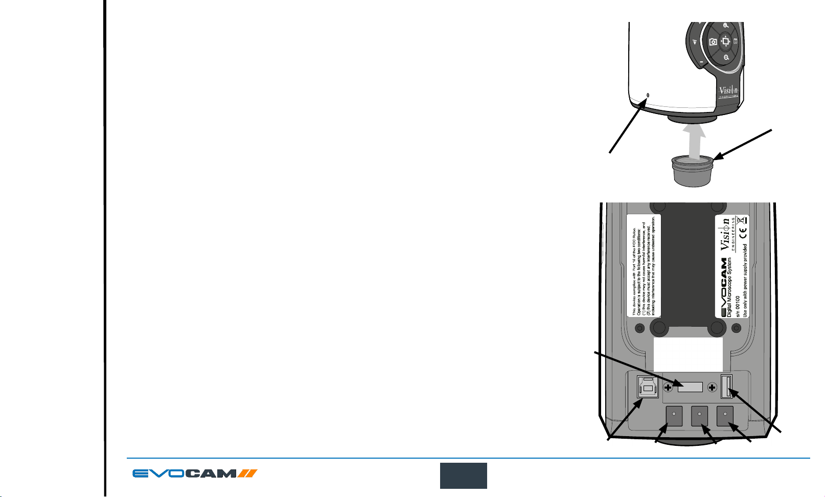
Objective lens
Exit
Contents
Preface
Assembly
Operation
Maintenance
Specication
System Diagram
Start page
` While holding the objective lens u in position, use the HEX key supplied to secure the lens by tightening
the grub screw v nger tight.
Do not over tighten the grub screw holding the lens in place.
u
Cabling
` Plug the HDMI cable into the EVO Cam II connector u and the other end into your HDMI-compatible
monitor or TV.
` The USB3 connetor
` Plug the power supply into a mains socket. Plug the power lead from the power supply into the
EVO Cam II power connector
` If required, an external ringlight (option) can be used with EVO Cam II. Plug the external ringlight into
the rear panel connector
Only use a Vision Engineering-authorised external ringlight with EVO Cam II.
` Plug the transmitted substage illuminator cable into the connector y on the rear panel of EVO Cam II.
The transmitted substage illuminator is an option for use with the Ergo stand.
` Plug the external remote keypad (optional) into socket z at rear of EVO Cam II.
is used for video out and software control.
v
on the back of the unit.
w
of EVO Cam II.
x
u
v
v
x
w
z
y
12
ASSEMBLY
Page 13
OPERATION
Exit
Contents
Preface
Assembly
Operation
Maintenance
Specication
System Diagram
Start page
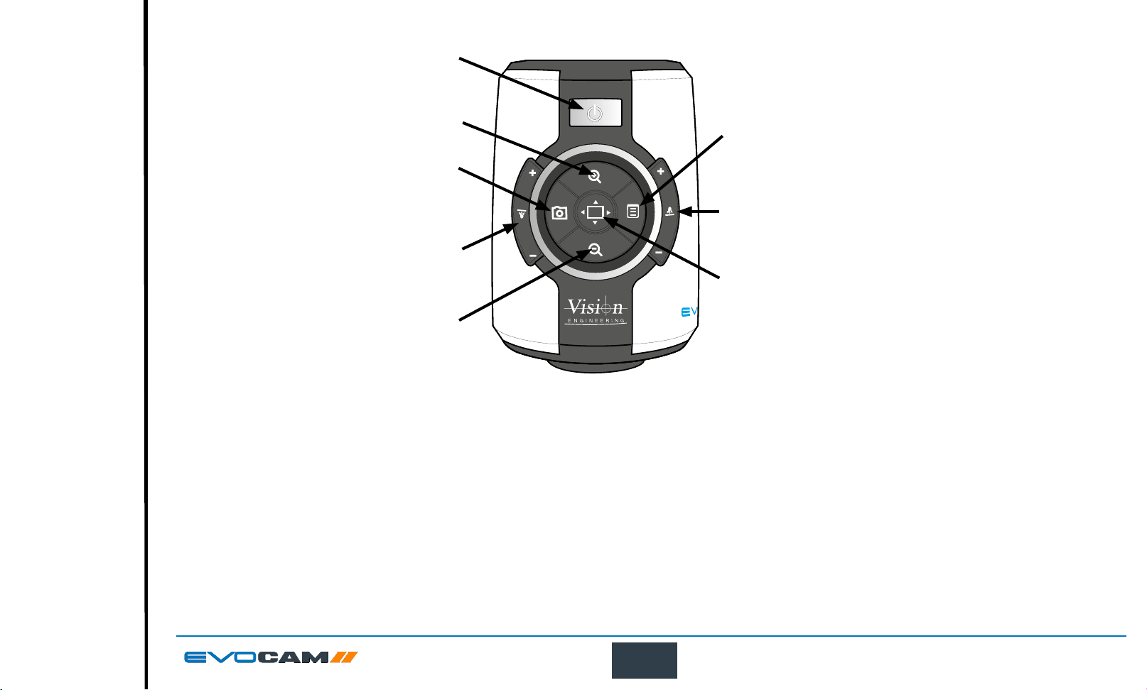
Quick start
Power on/off
u
Zoom in
v
Zoom out
w
Image capture
x
Transmitted substage illuminator (option)
y
Overview mode
z
Ringlight illumination control
{
Menu
|
Power on/off
- Short press = Power on
u
- Long press = Power off
Zoom control
- Zoom in
v
- Zoom out
w
Image capture
- Capture image
x
Transmitted substage illuminator (option)
- Press ‘+’ to increase brightness
y
- Press ‘–’ to decrease brightness
Press and hold ‘+’ or ‘-’ for fast change to illumination.
Short press ‘+’ or ‘-’ for ne adjustment
Overview mode
- Short press = Activate overview mode
z
(Press any button to exit overview mode)
u
v
x
y
w
|
{
z
Ring-light illumination control
- Press ‘+’ to increase brightness
{
- Press ‘–’ to decrease brightness
Press and hold ‘+’ or ‘-’ for fast change to
illumination.
Short press ‘+’ or ‘-’ for ne adjustment
Menu
- Short press = Access camera menu
|
(see page 16)
- Short press = exit menu
x
Image brightness shortcut
In AE or AP mode while on the main screen.
- Long press (3s) to activate the image
|
brightness shortcut
- Press to increase image brightness
v
Not available in ME mode.
13
OPERATION
Page 14
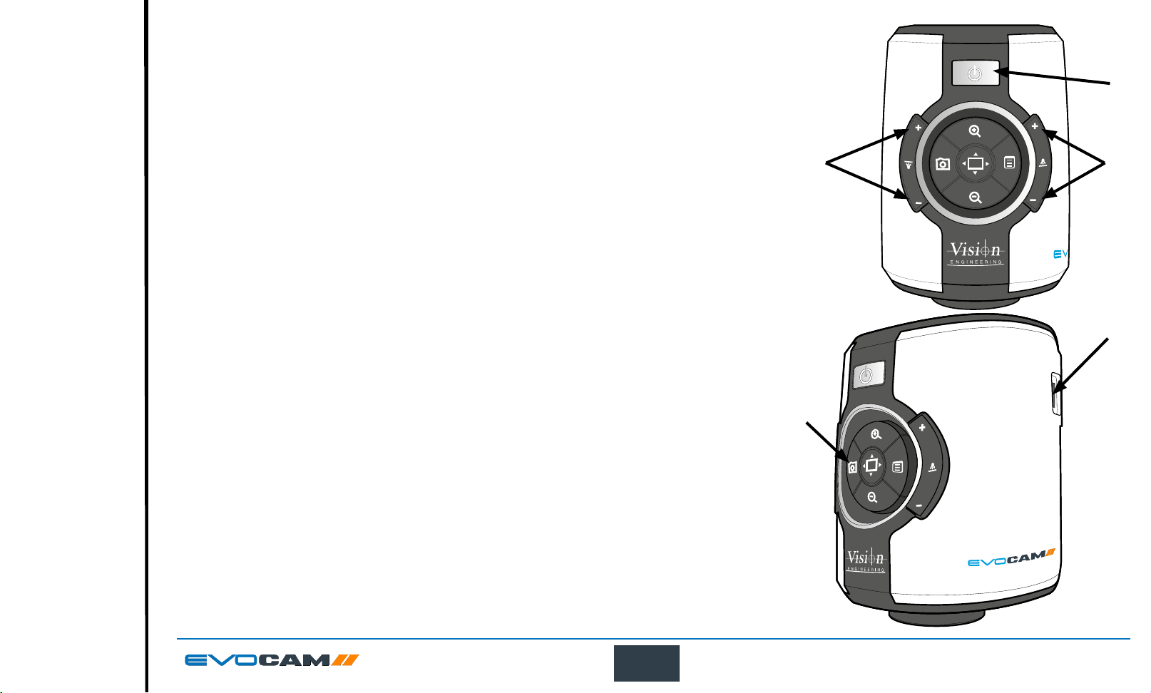
Control functions
Exit
Contents
Preface
Assembly
Operation
Maintenance
Specication
System Diagram
Start page
Power on/off
When the system is plugged in the unit will take approximately 8 seconds before it can power on properly
` Push the power button u to turn the unit on. After four beeps and a few seconds the picture from
the camera will appear. If not, switch your monitor to the input used for EVO Cam II.
u
` There will also be a panel in the top left of the screen displaying the EVO Cam II’s current settings.
` To turn EVO Cam II off, hold the Power button in for approximately 2 seconds.
Illumination control
` The integrated ringlight illumination level can be adjusted by the right hand side buttons v.
` The optional sub-stage illuminator intensity can be adjusted using the left hand side buttons
` When connected, the external rightlight illumination level can be adjusted using the right hand
side buttons
Holding down the buttons will allow for faster control of the light settings.
The internal ringlight is disabled when an external ringlight is connected.
v
.
w
Image capture
` To use this feature, insert a USB memory stick into the USB port u.
` When the system has detected the USB memory stick it will report “USB Flash Drive Ready”
` When you have an image you want to capture, simply press the capture button
` The system will indicate the image is being saved to the drive. The image is saved as
a 1920 x 1080 (.png) format.
` The image name is Date and Time stamped and saved in the format “IMG-date.png” where the
date is arranged as in the camera settings(see page 24).
The USB memory stick must be in FAT File System Format. It will not work with any other format.
When USB memory stick is removed “USB Flash Drive Removed” message is shown
v
.
w
.
v
u
v
14
OPERATION
Page 15
Magnication
Exit
Contents
Preface
Assembly
Operation
Maintenance
Specication
System Diagram
Start page
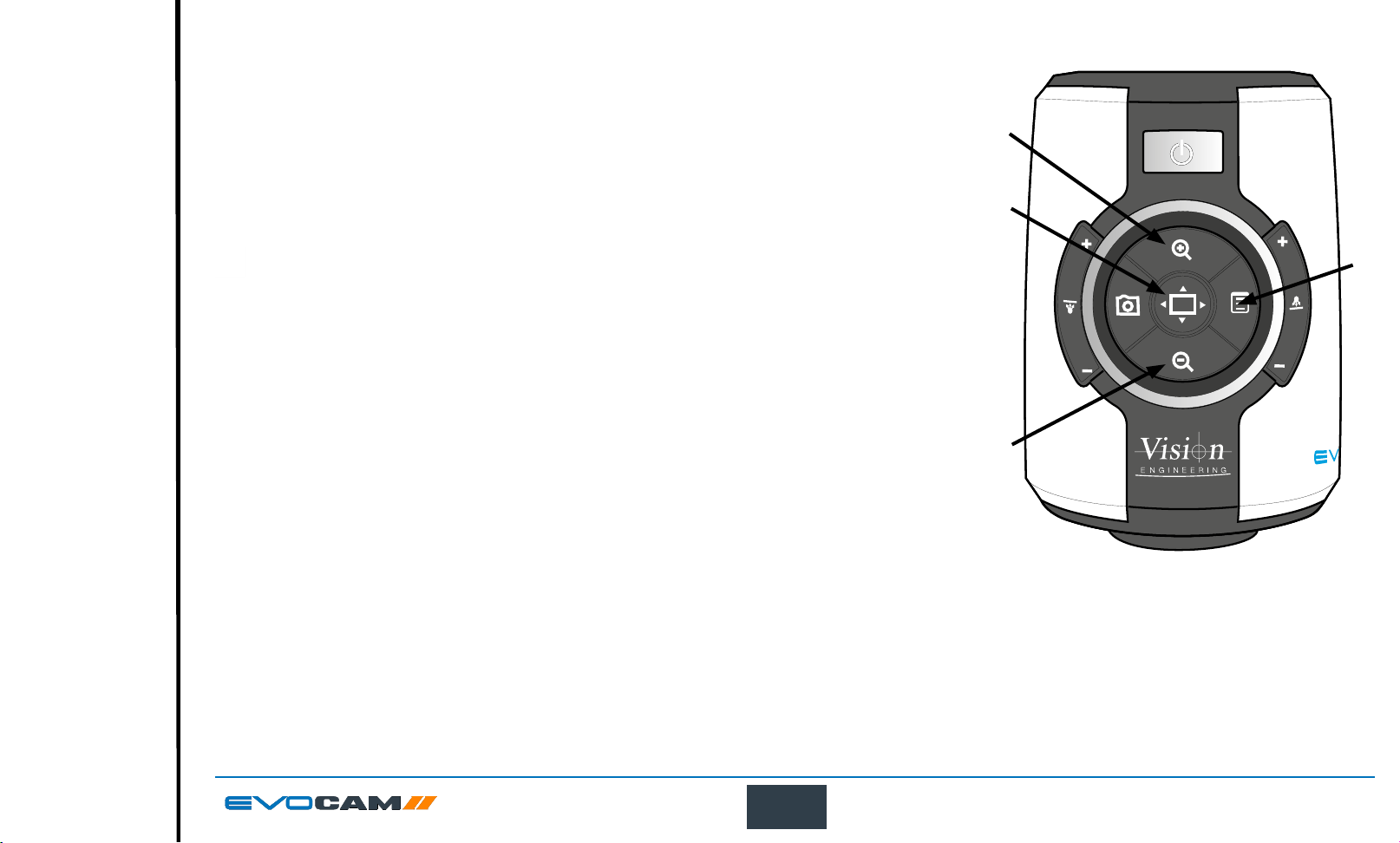
` Press the Zoom-In button u to enlarge the subject within the image and Zoom-Out button v to
reduce the subject size within the image. The unit will make a sound to indicate when it has reached
maximum or minimum zoom limits.
Magnication level OSD (On Screen Display)
The current magnication level is displayed for example “x30“to show a magnication level of 30.
When the magnication changes from optical to digital zoom a‘d’ is also displayed, e.g. “x60d”
to indicate a magnication level of 60 including digital zoom.
u
w
When changing lenses or monitor, the Screen Size and Lens Power settings need to be changed
using the menu options (see page 21) to ensure the correct magnication is displayed.
Overview
Overview allows you to easily locate a point of interest on the object you are viewing.
` Press and release the Overview button
` Place the point of interest in the centre of the screen and press any key to restore the magnication
to the previous level.
to make the camera zoom out fully.
w
x
v
15
OPERATION
Page 16
Main menu options
Exit
Contents
Preface
Assembly
Operation
Maintenance
Specication
System Diagram
Start page
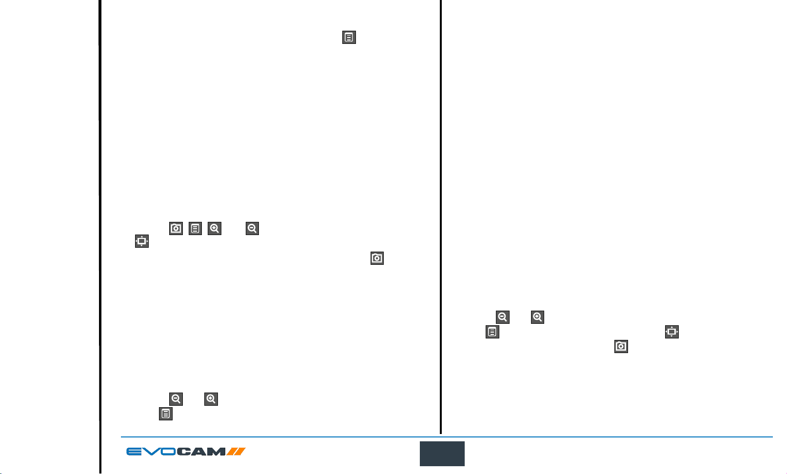
` To access the Main Menu press the Menu button .
Exposure options
The following main exposure options are available:
Auto exposure
Aperture priority
Manual exposure
` Use the
button to make a selection.
` To Exit the menu simply press the image capture button
longer displayed.
The following main menu options are available:
Exposure
Focus
Calibration
Measurement
Presets
Settings
` Use the
press to display the relevant sub-menu.
, , , and buttons to navigate the menu, and the
and buttons to select the option required and then
until it is no
` Use the
press to enter the relevant settings screen or to select the option
with the current settings then press to return to the main menu.
16
and buttons to highlight the option required and then
OPERATION
Page 17
Auto exposure
Exit
Contents
Preface
Assembly
Operation
Maintenance
Specication
System Diagram
Start page
Using this option, exposure is calculated and adjusted automatically. Target
brightness can be set to users desired level.
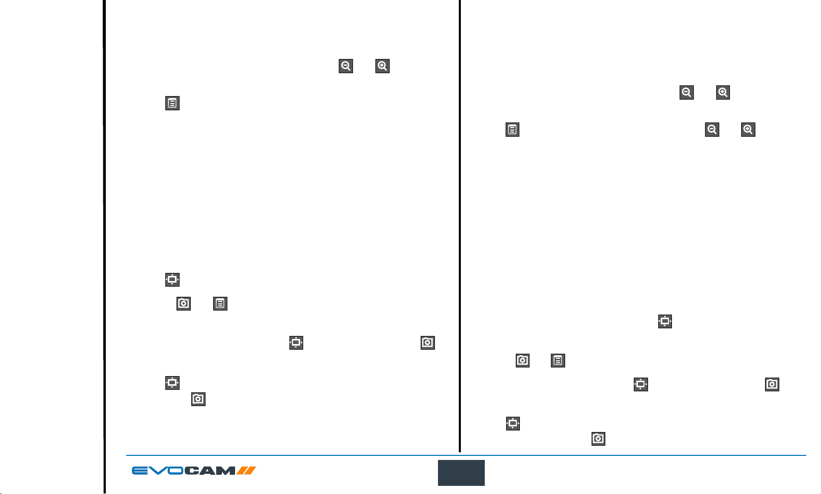
` With the exposure options displayed, use the
highlight automatic exposure (AE).
` Press
to display the highlighted brightness setting.
and buttons to
Aperture priority
This option allows the exposure to be calculated automatically when the user
sets the aperture value (F14 – F1.6 & closed). This allows easy control of the
depth of eld while maintaining the correct exposure. Target brightness can
be set to users desired level.
` With the exposure options displayed, use the
highlight aperture priority (AP).
and buttons to
` Press
` Use the
required.
` With the required value set, press
return to the exposure menu.
` Press
then press to return to the main menu.
to enable the value to be altered if necessary.
and buttons to decrease or increase the value as
to turn on the blue indicator next to the option to select it
to store it and then press to
` Press
highlight either the f-number option or the brightness option.
` With the required option selected, press
altered if necessary.
` Use the
` With the required values set, press
return to the exposure menu.
` Press
been selected then press to return to the main menu.
to display the AP options and then use the and buttons to
to enable the value to be
and buttons to decrease or increase the value as required.
to store it and then press to
to turn on the blue indicator next to the option to ensure it has
17
OPERATION
Page 18
Manual exposure
Exit
Contents
Preface
Assembly
Operation
Maintenance
Specication
System Diagram
Start page
This option enables exposure controls to be set manually. Aperture, Gain and
Exposure time can all be adjusted. Aperture (F14 – F1.6 & closed), Gain (1 -
15) and Exposure time (1/10,000 – 1s)
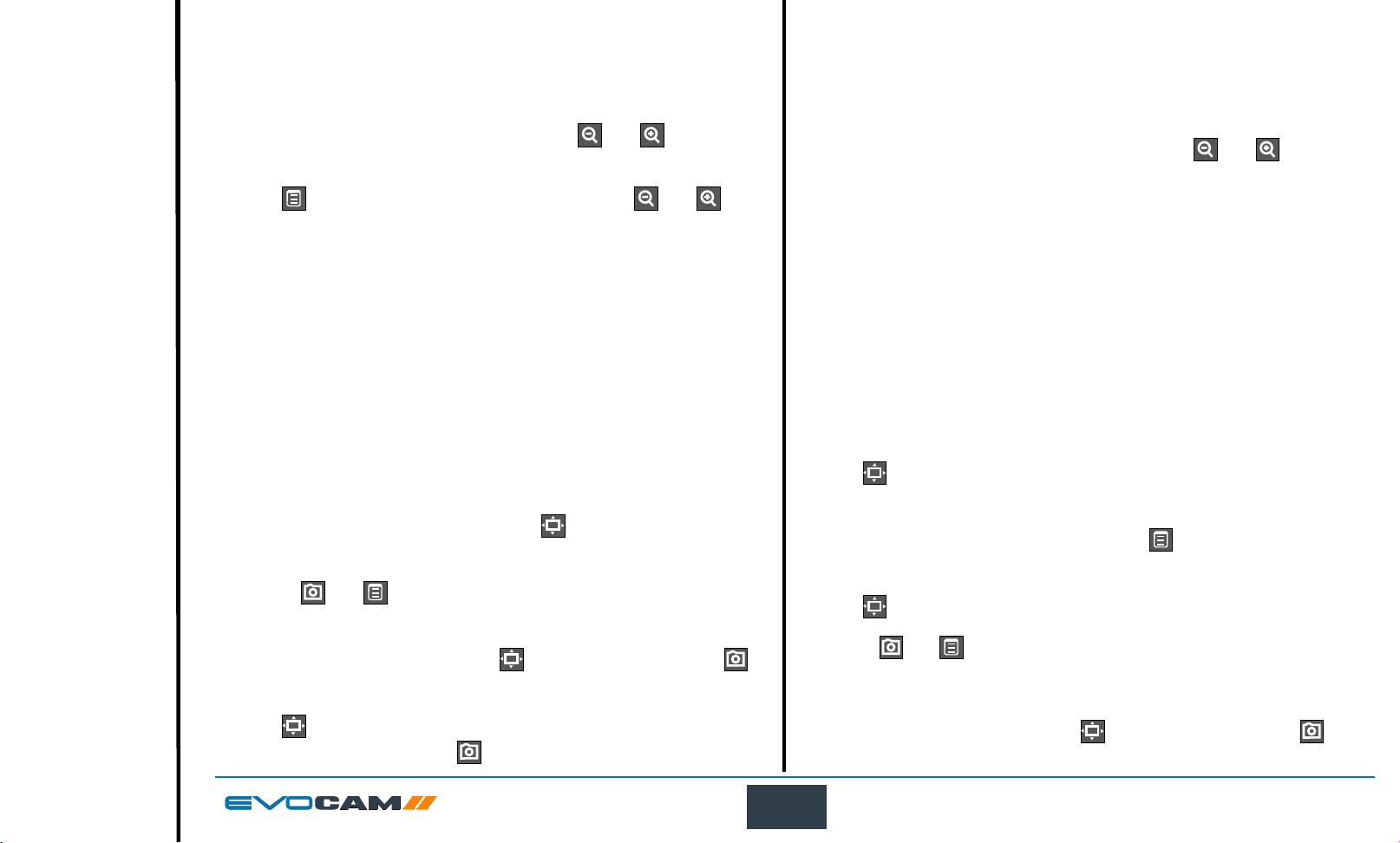
` With the exposure options displayed, use the
highlight manual exposure (ME).
` Press
buttons to highlight either the f-number, gain, or exposure time option.
to display the ME options and then use the and
and buttons to
Focus options
Auto/Manual focus
This option allows the user to set the EVO Cam II’s focus to be set
automatically if the subject is within range, or set a specic focal distance.
` With the focus options (AF/MF) displayed, use the
highlight automatic or manual focus as required.
and buttons to
` With the required option selected, press
altered if necessary.
` Use the
required.
` With the required values set, press
return to the exposure menu.
` Press
has been selected then press to return to the main menu.
and buttons to decrease or increase the value as
to turn on the blue indicator next to the option to ensure it
to enable the value to be
to store it and then press to
` Press
ensure it has been selected.
` If the manual focus option is selected, press
setting.
` Press
` Use the
If the focus position is not set to ‘Inf’ the zoom will not maintain
` With the required values set, press to store it and then press to
return to the focus menu.
18
to turn on the blue indicator next to the required option to
to display the distance
to enable the value to be altered if necessary.
and buttons to decrease or increase the value as required.
parfocality.
OPERATION
Page 19
Calibration
Exit
Contents
Preface
Assembly
Operation
Maintenance
Specication
System Diagram
Start page
Before setting a calibration, ensure the unit is in Manual Focus
mode at Inf. When a calibration is set, the unit is automatically set
to Manual Focus mode and this can cause the object to move out of
focus if working in Automatic Focus mode.
` With the calibrate options ( ) displayed, use the and buttons
to highlight the option required and then press to enable the value
to be altered if necessary.
Scale
` Use the
can be viewed on the monitor that will be used for calibration.
Right calibration line
` Use the and buttons to set the position of the right calibration line
as displayed on the screen.
Left calibration line
` Use the and buttons to set the position of the left calibration line
as displayed on the screen.
Calibration
` Press
` CAL will be displayed in top left corner of the Status bar
` Features that affect the calibration will be disabled while the calibration is
active. Press
and buttons to set the size of the calibration piece that
to activate calibrated measurements.
again to turn this feature off to reactivate disabled features.
19
OPERATION
Page 20
Measurement
Exit
Contents
Preface
Assembly
Operation
Maintenance
Specication
System Diagram
Start page
` With the measurement options ( ) displayed, use the and
buttons to highlight the option required and then press to highlight
and then enable the value to be altered if necessary.
Grid
This option enables a grid to be displayed on the screen. Both the size and
position of the grid can be altered as follows:
Calibration can be carried out with this option set.
No units will be shown if calibration is not set
The grid measurement units and colour can be altered using the settings
option (see page 22 and page 24 respectively).
` Use the and buttons to highlight either grid size ( ) or grid
position ( ) and then press to select it in order to change its value.
Cursor
This option enables a measurement to be made between moveable cursors.
Calibration can be carried out with this option set. No units will be
shown if calibration is not set.
The cursors’ measurement units and colour can be altered using the
settings option (see page 22 and page 24 respectively).
` Use the and buttons to highlight either the top left cursor ( ) or
lower right cursor ( ) and then press to select it in order to change
its position.
` Use the
position and then press to save the altered position and return to the
cursor option.
` Press
, , and buttons to adjust the selected cursor’s
to return to the measurement options.
` Use the
then press to save the altered setting and return to the grid option.
` Press
Off
` Press
Overlay
An overlay le can be imported and displayed for comparison with a live
image. The le must be PNG format with transparent background, and must
match the camera image size (1920x1080 pixels). Files of different sizes
will align to the top left corner of the image. Overlay les must be named
‘“EVOCam_overlay.png”.
` Use the
press to activate it.
ON: Turn the overlay on
OFF: Turn the overlay off
IMPORT: Import overlay le from USB stick.
CLEAR: Clears overlay le from the memory.
Importing an overlay le will overwrite any existing overlay le
already imported.
, , and buttons to adjust the selected grid value and
to return to the measurement options.
to ensure neither the cursor or the grid are displayed.
and buttons to highlight one of the following options then
20
OPERATION
Page 21
Presets and hotkeys
Exit
Contents
Preface
Assembly
Operation
Maintenance
Specication
System Diagram
Start page
Settings
The current camera settings can be saved as one of the 10 presets. These
settings can then be exported and subsequently imported, enabling
multiple EVO Cam II cameras to be standardised.
Any of the 10 presets can be assigned to one of the three hotkeys on the
optional remote keypad.
Presets
` With the presets options (
highlight the required preset and then press to select it.
` Press
following options:
Save: press
preset
Export: press to export the current settings to a USB stick
Import: press to import a preset le from a USB stick
` Press
Hotkeys
This option enables each of the three hot keys on the optional remote
keypad to have one of the 10 presets assigned to it.
` Press
buttons to highlight the required hotkey.
` Press
10 presets (or None) as required.
` Press
press to return to the preset options.
and then use the and buttons to enable one of the
to save the current EVO Cam II settings to the selected
to return to the preset options.
to highlight the Hotkeys option and then use the and
and then use the and buttons to highlight one of the
to assign the selected preset (or None) to the hotkey and then
) displayed, use the and buttons to
With the settings options ( ) displayed, use the and buttons to
select from the following:
Magnication
Image mode
User interface
System set up
Magnication
` With the magnication (
the and buttons to enable one of the following options:
Set screen size
Set lens power
Set measurement units
Set digital zoom
Set screen size
` With set screen size (
` To alter the screen size (its diagonal measurement), press
the and buttons to set the size between 1 and 100 inches.
` With the required value set, press
return to the magnication options.
Set lens power
` With set lens power (
Some lenses have two options; Optimal Field and Full Field. Optimum Field
has been designed to restrict minimum zoom to reduce any vignetting from
the set lens. Full Field allows the full zoom range of the lens.
` To alter the lens power, use the and buttons to highlight the
required value, press to store it and then press to return to the
magnication options.
) options highlighted, press and then use
) highlighted, press .
and then use
to store it and then press to
) highlighted, press .
21
OPERATION
Page 22
Set measurement units
Exit
Contents
Preface
Assembly
Operation
Maintenance
Specication
System Diagram
Start page
` With set measurement units (
) highlighted, press .
Black and white
` With set black and white ( ) highlighted, press .
` To alter the units, use the
inch, press to store the change and then press to return to the
magnication options.
Set digital zoom
` With set digital zoom (
` To turn digital zoom on or off, use the
the required state, press to store the change and then press to
return to the magnication options.
Image mode
` With the image mode (
the and buttons to enable one of the following options:
Auto white balance
Black and white
Wide dynamic range
Infra red mode
Capture button action
Auto white balance
` With auto white balance (
` To set auto white balance, press
progress’ message will be displayed for a short time.
` When the message is no longer displayed, press to return to the
image mode options.
and buttons to highlight either mm or
) highlighted, press .
and buttons to highlight
) option highlighted, press and then use
) highlighted, press .
. The ‘Auto white balance in
` To turn black and white on or off, use the
the required state, press to store the change and then press to
return to the magnication options.
Wide dynamic range
Wide Dynamic Range is only effective when in Automatic Exposure Mode.
Activate wide dynamic range to enhance image information in shadow and
highlight areas of high contrast subjects.
` With wide dynamic range (
` To turn wide dynamic range on or off, use the
highlight the required state, press to store the change and then press
to return to the magnication options.
Infra red mode
Activating the infra red mode removes internal infrared lter to extend the
range of sensitivity. Image is displayed in black and white to incorporate
infrared wavelengths. Optionally, IR-transmitting lters (IR720) can be added
to objectives for IR only imaging.
` With infra red mode (
` To turn infra red mode on or off, use the
the required state, press to store the change and then press to
return to the magnication options.
) highlighted, press .
) highlighted, press .
and buttons to highlight
and buttons to
and buttons to highlight
White Balance data is lost when the power is turned off. To reset
white balance please follow the procedure above.
22
OPERATION
Page 23
Capture button action
Exit
Contents
Preface
Assembly
Operation
Maintenance
Specication
System Diagram
Start page
Set this option to Freeze to freeze image on rst push of capture button.
Second press to capture. Or, to Save to save image on rst push of capture
button.
` With capture button action (
` To turn infra red mode save or freeze, use the
highlight the required state, press to store the change and then
press to return to the magnication options.
User interface
` With the user interface (
use the and buttons to enable one of the following options:
Language
Sound
Crosshair size
Crosshair colour
On screen display
Status bar
Transparency
Information text
) highlighted, press .
and buttons to
) option highlighted, press and then
Language
` With language (
` To select the required language, use the
on of the following:
English
French
German
Spanish
Italian
Portuguese
Russian
Chinese
Japanese
Korean
` Press
interface options.
Selecting the language changes the language of the information text
Sound
` With sound (
` To turn the sound on or off, use the
required state, press to store the change and then press to return
to the user interface options.
Crosshair size
` With crosshair size (
` To set the crosshair size to off, short or long, use the
to highlight the required state, press to store the change and then
press to return to the user interface options.
to store the change and then press to return to the user
only. Menu icons are not changed.
) highlighted, press .
and buttons to highlight
) highlighted, press .
and buttons to highlight the
) highlighted, press .
and buttons
23
OPERATION
Page 24
Crosshair colour
Exit
Contents
Preface
Assembly
Operation
Maintenance
Specication
System Diagram
Start page
` With crosshair colour (
` To set the crosshair colour, use the
required colour, press to store the change and then press to
return to the user interface options.
On screen display
` With on screen display (
` To set the on screen display position to upper left, upper right, lower
left, or lower right, use the
required position, press to store the change and then press to
return to the user interface options.
Status bar
` With status bar (
` To set the status bar to off, or position it to upper left, upper right,
lower left, or lower right, use the
required state or position, press to store the change and then press
to return to the user interface options.
Transparency
` With transparency (
` To alter the transparency, press
buttons to set the percentage transparency of the menu.
` Press to store the change and then press to return to the user
interface options.
Information text
` With information text (
` To turn the information text on or off, use the
highlight the required state, press to store the change and then
press to return to the user interface options.
) highlighted, press .
and buttons to highlight the
) highlighted, press .
and buttons to highlight the
) highlighted, press .
and buttons to highlight the
) highlighted, press .
and then use the and
) highlighted, press .
and buttons to
System set up
` With the system set up (
the and buttons to enable one of the following options:
Time (set time)
Date (set date and date format)
Reset (factory reset)
Frequency (set frame rate)
Import settings (load all settings from a USB stick)
Export settings (save all settings to a USB stick)
Time
` With time (
` To set the time, use the
or minutes (MIN) and then press to highlight the value.
` Use the
` Press
set up options.
Date
` With date (
` To change the date format, use the
required format and then press to store the change.
` To set the date, use the
month (MM) or year (YY) and then press to highlight the value.
` Use the
` Press
set up options.
) highlighted, press .
and buttons to set the required value.
to store the change and then press to return to the system
) highlighted, press .
and buttons to set the required value.
to store the change and then press to return to the system
) option highlighted, press and then use
and buttons to highlight either hours (HR)
and buttons to highlight the
and buttons to highlight either date (DD),
24
OPERATION
Page 25
Reset
Exit
Contents
Preface
Assembly
Operation
Maintenance
Specication
System Diagram
Start page
` To reset the EVO Cam II to its factory settings, ensure the reset icon (
is highlighted, press and then press to carry out the reset.
` Press to return to the system set up options.
Frequency
` With frequency (
` To select the required frame rate, use the
highlight the required frequency (50 or 60Hz), press to store the
change and then press
Import settings from a USB stick connected to the EVO Cam II
` To import all settings from a USB memory stick, ensure the import icon
(
) is highlighted, press and then press to carry out the
import.
) highlighted, press .
and buttons to
to return to the user interface options.
)
` Press
Export settings to a USB stick connected to the EVO Cam II
` To export all settings to a USB memory stick, ensure the export icon
(
` Press
to return to the system set up options.
) highlighted, press and then press to carry out the export.
to return to the system set up options.
25
OPERATION
Page 26
Using the remote keypad (optional)
Exit
Contents
Preface
Assembly
Operation
Maintenance
Specication
System Diagram
Start page
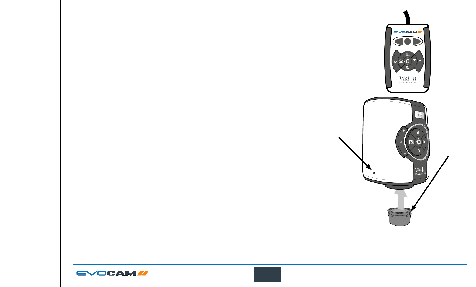
The optional remote keypad can be used with EVO Cam II and has identical controls to the EVO Cam II’s
front panel with the exception of the On/Off button but with the addition of three hotkeys (P1 to P3). These hotkeys
allow one of 10 presets to be assigned to each of them (see page 21).
` Press a hotkey (P1 to P3) to activate the preset settings allocated to the hot key.
Front Panel Lock
The remote keypad can be used to lock out the access to the menu from the front of the EVO Cam II unit.
` Press P2 for 3 seconds until ‘Front Panel Lock On’ is displayed on the screen.
` Disable the lock by following the same procedure.
Changing the camera objective lens
` Holding the lens barrel u from the bottom, use the HEX key supplied to partially unscrew the
grub screw v releasing the lens from its housing.
` While holding the objective lens
tightening the grub screw v.
Do not over tighten the grub screw holding the lens in place.
in position, use the HEX key supplied to secure the lens by
u
v
Using the Video Out via USB 3.
P3
P1
P2
PRESET
u
` Connect the USB 3 cable supplied with the system to the connection on the back of the EVO Cam II unit.
` Connect the other end of the cable to a free USB3 port on a PC.
` The video output from the camera is a Direct Show Video signal which can be used by a wide
range of video viewers. (Windows 10 Camera App, AMCap, and many others)
` A number of software suites are available from Vision Engineering which allow for control of the
camera functions via PC.
` Contact your local Vision Engineering Sales Representative for more information on the software available.
26
OPERATION
Page 27
MAINTENANCE
Exit
Contents
Preface
Assembly
Operation
Maintenance
Specication
System Diagram
Start page
Troubleshooting
Taking care of your EVO Cam II
Do not touch the lens. Dirt on the lens will appear as a blurred or dim image or as fuzzy spots on the screen. If you believe the lens is dirty, it can be cleaned with a
soft, dry cloth applying minimal pressure. As the lens is polished and coated, do not use a wet or coarse cloth, avoid detergents and abrasive substances or solvents to
clean it.
Never look directly at the LED light source for any prolonged period of time.
Use only the supplied power supply and inspect the cabling regularly for damage.
EVO Cam II contains a small battery to enable time and date settings to be retained while the unit is powered off. Should the battery need replacing
please contact you Vision Engineering representative who will be able to advise you.
FIRMWARE UPGRADE
Firmware upgrade
EVO Cam II includes a Firmware Upgrade Function allowing users to install new versions of the rmware.
Any update les will be provided directly from Vision Engineering.
` Place upgrade le on USB stick
` Insert stick into EVO Cam II
` Ensure EVO Cam II is in Standby State (e.g. unit is powered on at the mains, but not switched on and the power LED is not lit)
` Hold down Zoom In + Zoom Out, then simultaneously press the Power button until front panel LED starts ashing red.
` The ashing will stop when software update is complete
` Power off the unit at the mains and switch on again.
` Unit can be powered on as usual
` Verify the software update by checking the unit software version number (navigate on the menu to the information text option (i) and press the overview
button while the (i) is highlighted)
27
MAINTENANCE
Page 28
SPECIFICATION
Exit
Contents
Preface
Assembly
Operation
Maintenance
Specication
System Diagram
Start page
Camera resolution:
Monitor connections:
Monitor requirements:
Outputs:
Image capture:
Dimensions:
Power:
Operating temperature:
HD 1080p, 1920x1080 at 50/60 Hz
HDMI
HD ready or full HD (recommended)
HDMI, USB3.0
USB 2.0 High-speed
11 x 16.5 x 14 cm (w x h x d)
Max. 72 Watts - depending on external attachments
Storage: -10°C to +60°C. Operating: +5°C to +40°C
28
SPECIFICATION
 Loading...