

PART OBSOLETE - EOL18
Bulletin I2716 rev. F 06/03
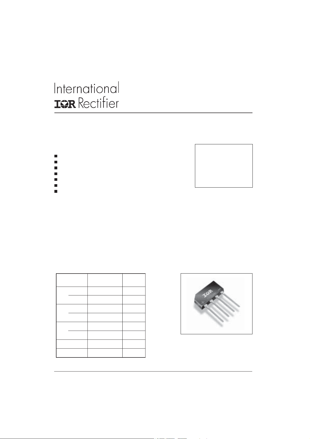
4GBL Series
4.0 Amps Single Phase Full Wave Bridge Rectifier
Features
Diode chips are glass passivated
I
Easy to assemble & install on P.C.B.
High Surge Current Capability
High Isolation between terminals and molded case (1500 V
Lead free terminals solderable as per MIL-STD-750 Method 2026
Terminals suitable for high temperature soldering at 260°C for 8-10 secs
UL E160375 approved
RMS
)
Description
V
RRM
= 4A
O(AV)
= 50/ 800V
These GBL Series of Single Phase Bridges consist
of four glass passivated silicon junction connected
as a Full Wave Bridge. These four junctions are
encapsulated by plastic molding technique. These
Bridges are mainly used in Switch Mode power
supply and in industrial and consumer equipment.
Major Ratings and Characteristics
Parameters 4GBL Units
I
O
@ T
C
I
@ 50Hz 150 A
FSM
@ 60Hz 158 A
I2t @ 50Hz 113 A2s
@ 60Hz 104 A2s
V
range 50 to 800 V
RRM
T
J
4A
50 °C
- 55 to 150
o
C
4GBL
www.irf.com
1
4GBL Series
Bulletin I2716 rev. F 06/03
ELECTRICAL SPECIFICATIONS
Voltage Ratings
Voltage V
Type number Code peak rev. voltage RMS voltage reverse voltage @ rated V
4GBL 005 50 35 75 5 400
01 100 70 150 5 400
02 200 140 275 5 400
04 400 280 500 5 400
06 600 420 725 5 400
08 800 560 900 5 400
, max repetitive V
RRM
TJ = T
max. TJ = T
J
VV VµAµA
, maximum V
RMS
max. T
J
, max non-repetitive I
RSM
= T
max. T
J
J
max. I
RRM
RRM
= 25°C T
J
Forward Conduction
Parameters 4GBL Unit Conditions
I
Maximum DC output current 4 A TC = 50°C, Resistive & inductive load
O
I
Maximum peak, one-cycle 150 t = 10ms, 20ms
FSM
non-repetitive surge current,
following any rated load condition 158 t = 8.3ms, 16.7ms TJ = 150°C
and with rated V
reapplied
RRM
I2t Maximum I2t for fusing, 113 A2s t = 10ms
initial TJ = TJ max 104 t = 8.3ms
V
Maximum peak forward voltage 0.975 V TJ = 25 oC, IFM = 4A
FM
per diode
I
Typical peak reverse leakage 5 µA TJ = 25 oC, 100% V
RM
curren t per diode
V
Maximum repetitive peak 50 to 800 V
RRM
reverse voltage range
3.2 TC = 50°C, Capacitive load
RRM
max.
RRM
@ rated V
= 150°C
J
RRM
Thermal and Mechanical Specifications
Parameters 4GBL Unit Conditions
T
Operating and storage -55 to 150
J
T
temperature range
stg
R
Max. thermal resistance 6.5 °C/ W DC rated current through bridge (1)
thJC
junction to case
R
Thermal resistance, 22 °C/ W D C rated current through bridge (1)
thJA
junction to ambient
W Approximate weight 2 (0.07) g (oz)
Note (1): Devices mounted on 75 x 75 x 3 mm aluminum plate
2
o
C
www.irf.com
Ordering Information Table
Device Code
4GBL Series
Bulletin I2716 rev. F 06/03
4 GBL 08
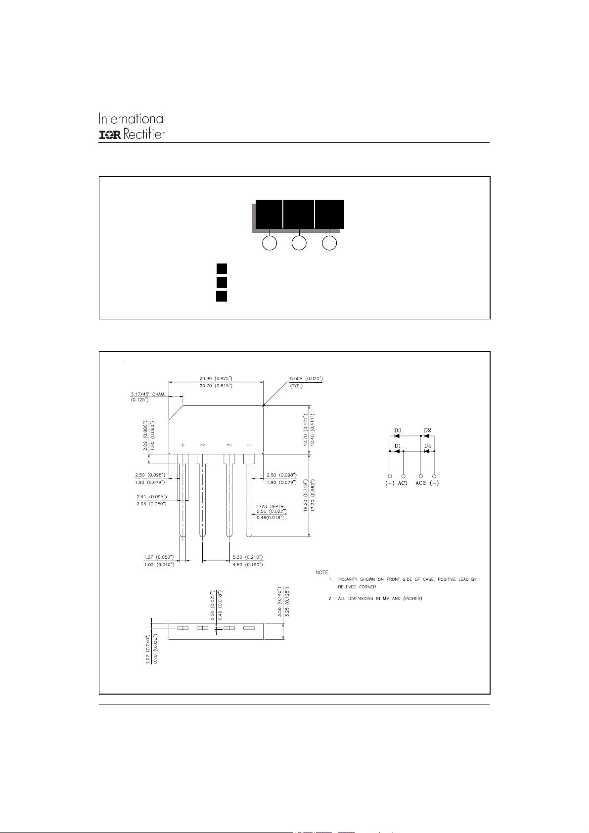
Outline Table
1
1 - Bridge current
2 - Basic Part Number
3 - Voltage Code: code x 100 = V
2
3
RRM
www.irf.com
All dimensions are in millimetres
3

4GBL Series
Bulletin I2716 rev. F 06/03
160
140
4GBL Series
120
180˚
100
(Rect)
80
60
180˚
(Sine)
40
20
Maximum Allowable Case Temperature (°C)
012345
Average Forward Current (A)
Fig. 1 - Current Ratings Characteristics
7
6
5
180˚
(Sine)
180˚
(Rect)
4
3
2
1
4GBL Series
T = 150˚C
J
1000
100
10
T = 25˚C
J
T = 150˚C
J
1
Instantaneous Forward Current (A)
0.1
0 0.5 1 1.5 2 2.5 3 3.5
Instantaneous Forward Voltage (V)
Fig. 2 - Forward Voltage Drop Characteristics
160
At Any Rated Load Condition And With
Rated Vrrm Applied Following Surge.
140
120
4GBL Series
Initial Tj = 150˚C
@ 60 Hz 0.0083 s
@ 50 Hz 0.0100 s
100
80
60
4GBL Series
0
Maximum Average Forward Power Loss (W)
01234
Average Forward Current (A)
Fig. 3 - Total Power Loss Characteristics
4
40
Peak Half Sine Wave Forward Current (A)
1 1 0 100
Number of Equal Amplitude Half Cycle Current Pulses (N)
Fig. 4 - Maximum Non-Repetitive Surge Current
www.irf.com

4GBL Series
Bulletin I2716 rev. F 06/03
Data and specifications subject to change without notice.
This product has been designed and qualified for Multiple Level.
Qualification Standards can be found on IR's Web site.
IR WORLD HEADQUARTERS: 233 Kansas St., El Segundo, California 90245, USA Tel: (310) 252-7105
TAC Fax: (310) 252-7309
Visit us at www.irf.com for sales contact information. 06/03
www.irf.com
5
 Loading...