

Villa Ralco Service manual
R605DASM
SISTEMA DI COLLIMAZIONE RADIOLOGICA
RADIOLOGICAL COLLIMATING SYSTEM
MANUALE ISTRUZIONI / INSTRUCTIONS MANUAL
MTR605/025/DASM - R605/027/DASM - R605/170/DASM
Data Emissione:
Date of Issue:
26.07.2006 06.11.2007
Livello di Revisione:
Revision Level:
Emesso da:
Issued by:

R605DASM
AUTOMATICO A AUTOMATIC
DIGITALE D DIGITAL
DOPPIO FILTRO DF DOUBLE FILTER
DOPPIA LAMELLA DL DOUBLE SHUTTER
LAMELLE FILTRANTI F FILTERING
SHUTTERS
MOTORI PASSO-
PASSO
LIVELLO REVISIONE/REVISION LEVEL:
This manual is a translation of the Italian text, which pervails in case of
doubts.
Rev. N Data/Date N Descrizone/Description
A
B 06.11.2007 MRE/29/07 Board updating
06.09.2007 MRE/14/07 Board updating
SM STEPPING MOTORS
Aggiornamento scheda
Aggiornamento scheda

Modello/Model R605DASM
CONTENTS
livello revisione/revision level: - - - - - - - - - - - - - - - - - - - - - - - - - - - - - iv
A - AVVISI / FRONT MATTER
B - DESCRIPTION
Characteristics: - - - - - - - - - - - - - - - - - - - - - - - - - - - - - - - 2
Versions: - - - - - - - - - - - - - - - - - - - - - - - - - - - - - - - - - - 3
R605/170/DASM- - - - - - - - - - - - - - - - - - - - - - - - - - - - - 3
R605/025/DASM- - - - - - - - - - - - - - - - - - - - - - - - - - - - - 4
R605/027//DASM - - - - - - - - - - - - - - - - - - - - - - - - - - - - 5
C - SPECIFICHE/SPECIFICATIONS
Validation of specification data: - - - - - - - - - - - - - - - - - - - - - - - 2
Classification - - - - - - - - - - - - - - - - - - - - - - - - - - - - - - - - 2
Operation environment: - - - - - - - - - - - - - - - - - - - - - - - - - - - 2
D - SIMBOLI/SYMBOLS
E - COMPATIBILITY WITH X-RAY TUBES
F - MOUNTING THE COLLIMATOR TO THE X-RAY TUBE
Mechanical installation of the external interface unit: - - - - - - - - - - - - - 3
G - COLLEGAMENTO ELETTRICO/ELECTRIC CONNECTION
Collegamento/Connection R605 DASM: - - - - - - - - - - - - - - - - - - - 1
H - ELECTRICAL POWER CONNECTION OF THE EXTERNAL UNIT TO THE GENER-
AL SYSTEM
- - - - - - - - - - - - - - - - - - - - - - - - - - - - - - - - - - - - - 3
Collegamento elettrico - ASR003 - - - - - - - - - - - - - - - - - - - - - 4
I - ELECTRONIC SYSTEM, DESCRIPTION:
Electric connections to the board: - - - - - - - - - - - - - - - - - - - - - - - - - - -2
JI - Programmazione/Programming- - - - - - - - - - - - - - - - - - - - - - 2
J2 - Rete CAN-BUS / CAN-BUS network - - - - - - - - - - - - - - - - - - 2
J3 - Fotocellule/Photocells - - - - - - - - - - - - - - - - - - - - - - - - - - 2
J4 - Display - - - - - - - - - - - - - - - - - - - - - - - - - - - - - - - - - 3
J5 - Motore / Motor - - - - - - - - - - - - - - - - - - - - - - - - - - - - - 3
J6 - Alimentazione / Supply - - - - - - - - - - - - - - - - - - - - - - - - - 3
- - - - - - - - - - - - - - - - - - - - - - - - - - - - - - - - - - - - - - - 4
CAN BUS INTERFACE - - - - - - - - - - - - - - - - - - - - - - - - - - 5
ID - Identifications - - - - - - - - - - - - - - - - - - - - - - - - - - - - - 6
ID 700h (model) - - - - - - - - - - - - - - - - - - - - - - - - - - - - - 6
ID 701h (state) - - - - - - - - - - - - - - - - - - - - - - - - - - - - - - 6
ID 702h (controls) - - - - - - - - - - - - - - - - - - - - - - - - - - - - 6
ID 703h (serial number) - - - - - - - - - - - - - - - - - - - - - - - - - 7
MTR605DASM_ingTOC.fm
ID 704h (drive mode)- - - - - - - - - - - - - - - - - - - - - - - - - - - 7
MANUALE ISTRUZIONI / INSTRUCTIONS MANUAL
MTR605/025/DASM - R605/027/DASM - R605/170/DASM
i/ i

Modello/Model R605DASM
ID 705h (drive speed)- - - - - - - - - - - - - - - - - - - - - - - - - - - 8
ID 706h (Options) - - - - - - - - - - - - - - - - - - - - - - - - - - - -10
Procedure - - - - - - - - - - - - - - - - - - - - - - - - - - - - - - - - - -12
J - ASR003 - EXTERNAL BOARD DESCRIPTION
Characteristics: - - - - - - - - - - - - - - - - - - - - - - - - - - - - - - - 1
Description:- - - - - - - - - - - - - - - - - - - - - - - - - - - - - - - - - 1
ASR003 - Wiring diagrams/Disegni elettrici - - - - - - - - - - - - - - - - - - - - 4
K - ASR003 BOARD
Configuration - - - - - - - - - - - - - - - - - - - - - - - - - - - - - - - - 1
FFD configuration - - - - - - - - - - - - - - - - - - - - - - - - - - - - - - - - - - - - - - - - 1
FFD Measuring Source: - - - - - - - - - - - - - - - - - - - - - - - - - - - 1
Focus Distance: - - - - - - - - - - - - - - - - - - - - - - - - - - - - - - - 1
Hystereris on FFD change - - - - - - - - - - - - - - - - - - - - - - - - - - 1
FFD Observation time - - - - - - - - - - - - - - - - - - - - - - - - - - - - 1
Format configuration - - - - - - - - - - - - - - - - - - - - - - - - - - - - - - - - - - - - -1
Format programmes: - - - - - - - - - - - - - - - - - - - - - - - - - - - - 1
Format Selection Mode: - - - - - - - - - - - - - - - - - - - - - - - - - - - 2
Format Source - - - - - - - - - - - - - - - - - - - - - - - - - - - - - - - 2
Configuration of manual movments controls - - - - - - - - - - - - - - - - - - -2
Movments controls: - - - - - - - - - - - - - - - - - - - - - - - - - - - - - 2
FFD Mode - - - - - - - - - - - - - - - - - - - - - - - - - - - - - - - - - 2
Operation modes - - - - - - - - - - - - - - - - - - - - - - - - - - - - - - - - - - - - - - - -2
Axes Reset modes: - - - - - - - - - - - - - - - - - - - - - - - - - - - - - 2
Calibration Mode: - - - - - - - - - - - - - - - - - - - - - - - - - - - - - - 2
Manual Mode: - - - - - - - - - - - - - - - - - - - - - - - - - - - - - - - 3
Default formats - - - - - - - - - - - - - - - - - - - - - - - - - - - - - - - 4
ASR003 - Calibrazione\Calibration - - - - - - - - - - - - - - - - - - - - - - - - - - - 5
Calibration procedure - - - - - - - - - - - - - - - - - - - - - - - - - - - - 5
L - SYSTEM CALIBRATION
M - ADJUSTMENTS
Iris Motor Adjustment: - - - - - - - - - - - - - - - - - - - - - - - - - - - - - - - - - - - - 1
Motor gear - intermediate gear: - - - - - - - - - - - - - - - - - - - - - - 1
Intermediate gear- iris movement gear: - - - - - - - - - - - - - - - - - - 1
Adjustment of Iris Photocell - - - - - - - - - - - - - - - - - - - - - - - - - - - - - - - - 1
Adjustment of Shutter Motors - - - - - - - - - - - - - - - - - - - - - - - - - - - - - - - 1
Shutter gear - intermediate gear:- - - - - - - - - - - - - - - - - - - - - - 1
Motor gear: - - - - - - - - - - - - - - - - - - - - - - - - - - - - - - - 1
Adjustment of Shutter photocells - - - - - - - - - - - - - - - - - - - - - - - - - - - - 2
N - OPERATION INSTRUCTIONS
System setting- - - - - - - - - - - - - - - - - - - - - - - - - - - - - - - - 1
O - SUBSTITUTIONS, DISASSEMBLY, TRANSPORT
Substitution of the Iris Motor - - - - - - - - - - - - - - - - - - - - - - - - - - - - - - - 1
MTR605DASM_ingTOC.fm
Substitution of the Iris Photocell- - - - - - - - - - - - - - - - - - - - - - - - - - - - -1
MANUALE ISTRUZIONI / INSTRUCTIONS MANUAL
MTR605/025/DASM - R605/027/DASM - R605/170/DASM
i/ ii

Modello/Model R605DASM
Substitution of shutter Motors - - - - - - - - - - - - - - - - - - - - - - - - - - - - - -1
Substitution of Photocell Shutters. - - - - - - - - - - - - - - - - - - - - - - - - - - -2
Disassembly - - - - - - - - - - - - - - - - - - - - - - - - - - - - - - - - 2
Transport and storage: - - - - - - - - - - - - - - - - - - - - - - - - - - - - 2
P - ROUTINE MAINTENANCE
Cleaning recommendations - - - - - - - - - - - - - - - - - - - - - - - - - 1
Recommended maintenance programme: - - - - - - - - - - - - - - - - - - - 1
Q - TROUBLESHOOTING
R - PARTI DI RICAMBIO / SPARE PARTS
Etichetta/Label - - - - - - - - - - - - - - - - - - - - - - - - - - - - - - - 1
R605/DASM - - - - - - - - - - - - - - - - - - - - - - - - - - - - - - - 1
Esploso/Parts Breakdown: - - - - - - - - - - - - - - - - - - - - - - - - - - 2
R605DASM : - - - - - - - - - - - - - - - - - - - - - - - - - - - - - - 2
R605/025/DASM - - - - - - - - - - - - - - - - - - - - - - - - - - - - 3
R605/027/DASM - - - - - - - - - - - - - - - - - - - - - - - - - - - - 4
S - GENERAL
Repairs - - - - - - - - - - - - - - - - - - - - - - - - - - - - - - - - - - - - - - - - - - - - - - - - 1
End of life disposal - - - - - - - - - - - - - - - - - - - - - - - - - - - - - - - - - - - - - - - 1
Warranty - - - - - - - - - - - - - - - - - - - - - - - - - - - - - - - - - - - - - - - - - - - - - - 1
Components not covered by this warranty: - - - - - - - - - - - - - - - - - - 2
Safety/Responsibility - - - - - - - - - - - - - - - - - - - - - - - - - - - - - - - - - - - - - 3
T - FIGURE E SCHEMI / FIGURES AND DIAGRAMS
MTR605DASM_ingTOC.fm
MANUALE ISTRUZIONI / INSTRUCTIONS MANUAL
MTR605/025/DASM - R605/027/DASM - R605/170/DASM
i/ iii

A - AVVISI / FRONT MATTER
Modello/Model R605DASM
LE RADIAZIONI EMESSE SONO DANNOSE PER
L'OPERATORE E PER COLORO CHE SI TROVANO
NELLA VICINANZE A MENO CHE NON SIANO OS-
SERVATE CORRETTAMENTE LE PROCEDURE
PROTETTIVE. TUTTI COLORO CHE SONO AUTOR-
IZZATI A INTERVENIRE SULL'APPARECCHIATURA
RADIOLOGICA DEVONO CONOSCERE BENE LE
PROCEDURE RIGUARDANTI LA PROTEZIONE
CONTRO LE RADIAZIONI.
.
IL DISPOSITIVO SODDISFA I REQUISITI ESSENZIA-
LI DESCRITTI NELL'ALLEGATO 1 DELLA DIRETTI-
VA 93/42/CEE ED È CLASSIFICATO SECONDO
L'ALLEGATO IX IN CLASSE IIB.
IL COLLIMATORE È CONFORME ALLE NORME: IEC
601-1,
IL COLLIMATORE DEVE ESSERE INSTALLATO SU
UN SISTEMA RADIOLOGICO GENERALE CON-
FORME ALLA DIRETTIVA CEE 93/42
LA CORRETTA INSTALLAZIONE, UTILIZZO E MA-
NUTENZIONE DEL COLLIMATORE DOVREBBERO
ESCLUDERE PROBLEMI DI FUNZIONAMENTO DEL
COLLIMATORE STESSO E DEGLI APPARECCHI
CIRCOSTANTI IN QUANTO LA RALCO HA SUPER-
ATO LE PROVE EMC.
IEC 601-1-2, IEC 601-1-3.
X-RAYS ARE DANGEROUS TO BOTH OPERATOR
AND OTHERS IN THE VICINITY UNLESS ESTAB-
LISHED SAFE EXPOSURE PROCEDURES ARE
STRICTLY OBSERVED.
THOSE AUTHORISED TO OPERATE OR SERVICE
THE RADIOLOGICAL EQUIPMENT MUST BE THOR-
OUGHLY FAMILIAR WITH THE PROCEDURES RE-
GARDING RADIATION PROTECTION..
THE COLLIMATOR DESCRIBED HEREIN CON-
FORMS TO THE REQUISITES DESCRIBED IN AT-
TACHMENT 1AND IS CLASSIFIED CLASS IIB
ACCORDING TO ATTACHMENT IV OF CEE 93/42/
CEE DIRECTIVE. THE COLLIMATOR CONFORMS
TO ISTANDARDS IEC 60601-1, IEC 60601-1-2,
IEC 60601-1-3.
THE COLLIMATOR IS TO BE INSTALLED ON A
GENERAL PURPOSE RADIOLOGY UNIT CON-
FORMING TO DIRECTIVE CEE 93/42.
PROPER INSTALLATION, OPERATION AND MAIN-
TENANCE OF THE COLLIMATOR SHOULD EX-
CLUDE OPERATION PROBLEMS OF THE
COLLIMATOR AND OF THE SURROUNDING
EQUIPMENT SINCE RALCO HAS SUCCESSFULLY
PASSED EMC TESTING.
IL MANUALE ISTRUZIONI FORNISCE I RIFERIMEN-
TI SU STANDARD E OPTIONALS. VERIFICARE LA
VERSIONE ACQUISTATA SULL’ETICHETTA POSTA
SULL’APPARECCHIO O NELLA DOCUMENTAZIONE
AGGIUNTIVA..
CHIUNQUE SI TROVI AD UTILIZZARE QUESTO
MANUALE DEVE LEGGERLO ATTENTAMENTE E
PRESTARE ATTENZIONE AGLI AVVISI ED AI CON-
SIGLI IN ESSO CONTENUTI ANCHE NEL CASO IN
CUI LA PERSONA INCARICATA DEL MONTAGGIO
FOSSE ESPERTA DI COLLIMATORI RADIOLOGICI.
avvisi.fm
MANUALE ISTRUZIONI / INSTRUCTIONS MANUAL
MTR605/025/DASM - R605/027/DASM - R605/170/DASM
THE INSTRUCTIONS MANUAL SUPPLIES INDICA-
TIONS ON STANDARD OPTIONAL MATERIAL.
SPECIFIC DATA REGARDING THE VERSION PUR-
CHASED IS PROVIDED BY THE LABEL OR BY AN-
NEXED DOCUMENTATION.
THE USER OF THIS MANUAL IS DIRECTED TO
READ AND CAREFULLY REVIEW THE INSTRUC-
TIONS AND CAUTIONS CONTAINED HEREIN EVEN
IF THE PERSON IS PERFECTLY CONVERSANT
WITH THE INSTALLATION OF X-RAY COLLIMATOR.
A/ 1
Modello/Model R605DASM
VERIFICARE SUBITO DOPO L’INSTALLAZIONE LA
SICUREZZA DEL SISTEMA GENERALE.
QUANDO SI RENDE NECESSARIO SMONTARE LE
COPERTURE FARE ATTENZIONE A RIMONTARLE
CORRETTAMENTE – VEDI CAPITOLO - MA-
NUTENZIONE.
L'INSTALLAZIONE E LE RIPARAZIONI DEL COLLI-
MATORE DEVONO ESSERE EFFETTUATE DA PER-
SONE AUTORIZZATE DALLA CASA
COSTRUTTRICE DELL'APPARECCHIATURA RADI-
OGOLOGICA OPPURE DA PERSONA AUTORIZZA-
TA DALLA RALCO STESSA.
IL PERSONALE DEVE ESSERE A CONOSCENZA
DELLE NORMATIVE SULLA SICUREZZA.
QUESTO DOCUMENTO E' STATO REDATTO E DIS-
TRIBUITO DALLA RALCO SRL. PRODUTTRICE DEL
COLLIMATORE IN OGGETTO.
PER ULTERIORI INFORMAZIONI RIVOLGERSI A:
RALCO SRL - VIA DEI TIGLI 13/G - 20046 BIAS-
SONO (MI) - ITALIA
FAX: ++39-039-2497.799 - EMAIL:
RALCO@RALCO.IT
TEST THE GENERAL SYSTEM SAFETY IMMEDI-
ATELY AFTER ITS INSTALLATION.
WHENEVER THE COVERS REQUIRE TO BE RE-
MOVED CARE MUST BE TAKEN TO REMOUNT
THEM CORRECTLY - SEE CHAPTER ON MAINTE-
NANCE
COLLIMATOR INSTALLATION AND SERVICING IS
TO BE PERFORMED BY PERSONNEL AUTHOR-
ISED BY THE MANUFACTURE OF THE X-RAY
EQUIPMENT OR BY RALCO SRL.
PERSONNEL MUST BE FAMILIAR WITH THE
SAFETY STANDARDS COVERING ELECTROMEDI-
CAL EQUIPMENT
DOCUMENT IS A TRANSLATION FROM THE
THIS
ORIGINAL ITALIAN, PREPARED AND DISTRIBUTED
BY RALCO SRL MANUFACTURER OF THE X-RAY
COLLIMATOR DESCRIBED. ADDRESS ENQUIRIES
TO:
RALCO SRL -VIA DEI TIGLI 13/G -20046 BIASSO-
NO (MI) - ITALIA
FAX: ++39-039-2497.799 - EMAIL:
RALCO@RALCO.IT
avvisi.fm
MANUALE ISTRUZIONI / INSTRUCTIONS MANUAL
MTR605/025/DASM - R605/027/DASM - R605/170/DASM
A/ 2
Modello/Model R605DASM
B - DESCRIPTION
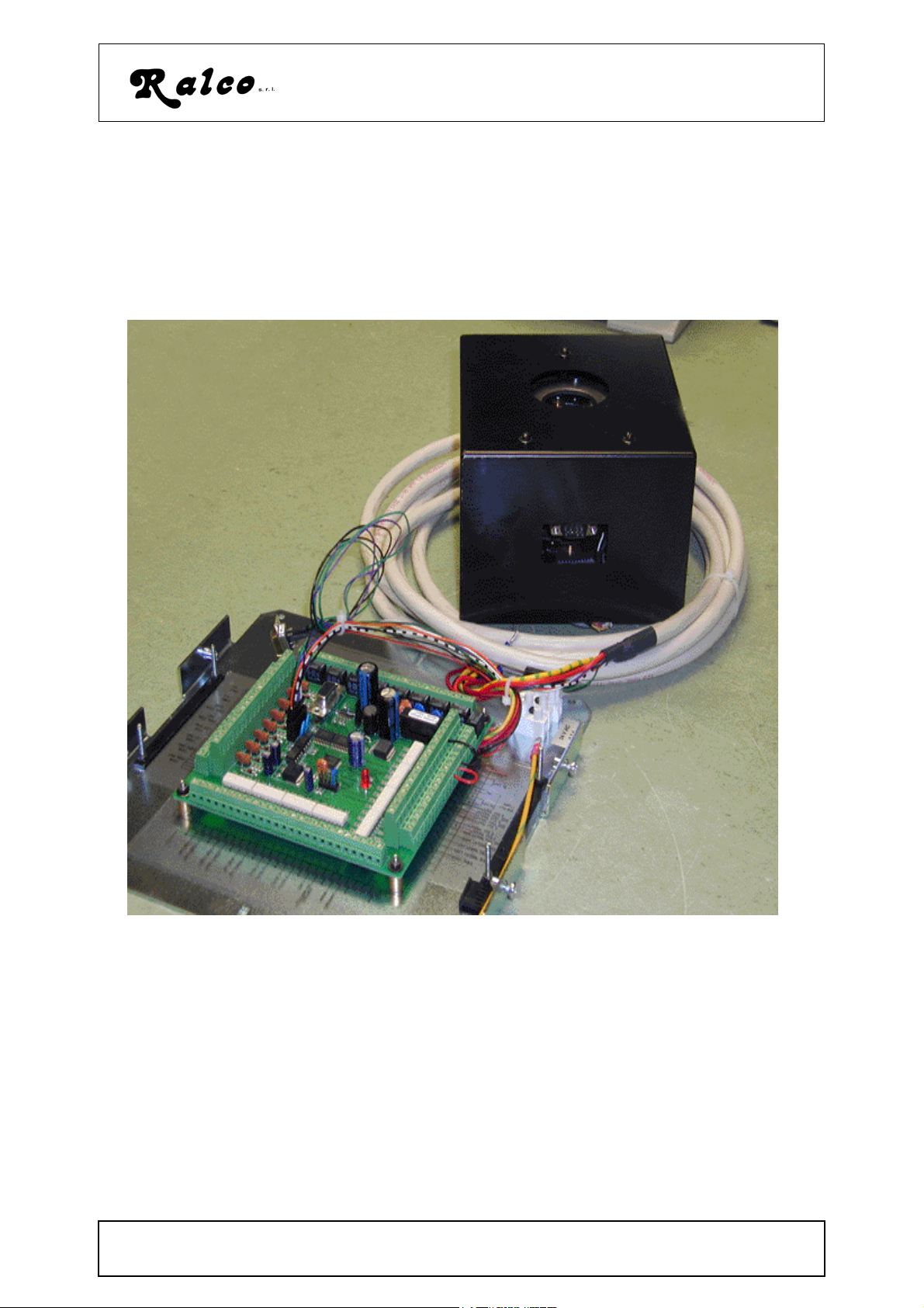
Compact radiological automatic collimating system for round and elliptic fields
designed to operate with a mobile "C" arm Image Intensifier equipment.
R605DASM
The round and elliptical fields are defined as follows: The round field by 8 lead shutters
located near the exit window and a brass cone near the x-ray focus; the elliptical field
by the round field and two pairs of lead rectangular shutters located near the collimator
entrance window.
Round and elliptical field shutters are controlled by 5 stepping motors.
The collimator features a microprocessor cuit built into the collimator to control the 5
stepping-motors via external signal source with CanBus protocol.
The circuits return a CanBus protocol signal to indicate correct motor positioning.
The two pairs of lead rectangular shutters move jointly and both rotate ± 360°.
descrizione_605DASM.fm
MANUALE ISTRUZIONI / INSTRUCTIONS MANUAL
MTR605/025/DASM - R605/027/DASM - R605/170/DASM
images\collimatori|605|605DASM
B/ 1
Modello/Model R605DASM
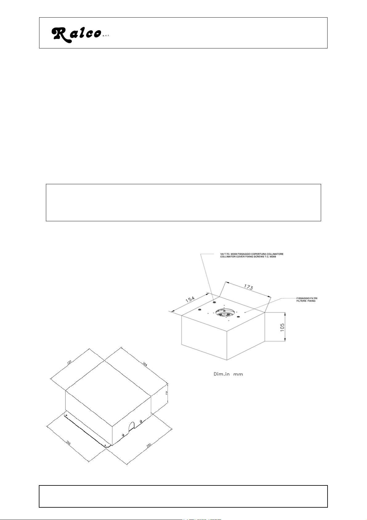
During rotation the ellitpic field remains steady , with a tolerance of ± 10 mm, at a Focus
Film Distance (FFD) of 100 cm.
The field dimension at FFD 100cm (39.4”) with the collimator mounted at 80 mm
(3.14") from the focus is 30 cm ( 12").
Characteristics:
• Radiation shielding 125 - 4 mA.
• Inherent filtration absent
• Round field variable from a minimum of 5cm to a maximum of 30 cm at 1m FFD.
The radiological collimator, with round and elliptic x-ray fields, is designed and constructed for installation with rotating or fixed anode x-ray tubes (EN 60601-1-3
par. 29.202.3). The motorised movement of its shutters permits adjustment of the xray field to the area under investigation.
NOTE:
TANDARD VERSION FORESEES 30 CM (12") AT A FOCUS DISTANCE OF 100CM, FOR LOWER
S
OPENING IT IS NECESSARY TO SUBSTITUTE THE SECONDARY COLLIMATOR.SPECIFY THE MAXIMUM
REQUIRED OPENING ON THE ORDER.
R605DASM
collimatori\605\dim_605\170\DASM.gif
descrizione_605DASM.fm
MANUALE ISTRUZIONI / INSTRUCTIONS MANUAL
MTR605/025/DASM - R605/027/DASM - R605/170/DASM
collimatori\dacs\scat_esterna:dac.gif
B/ 2
Modello/Model R605DASM
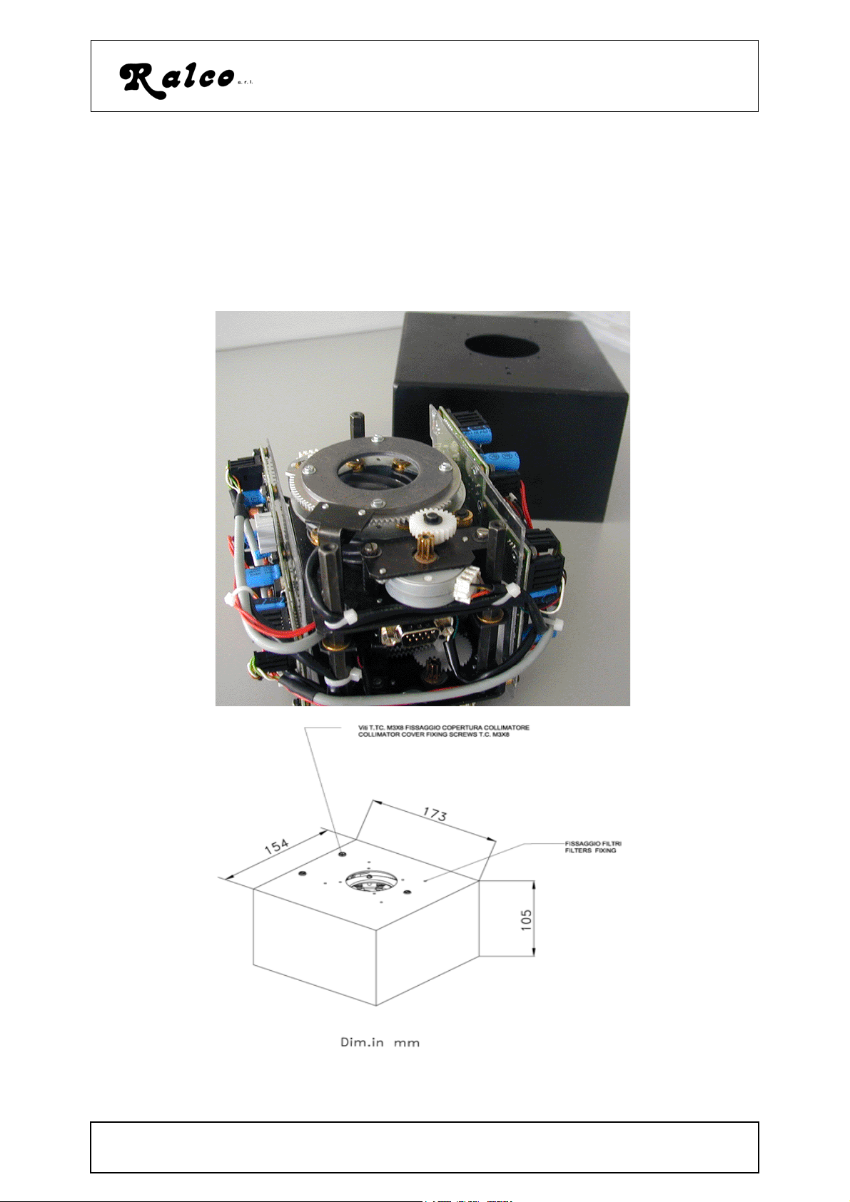
Versions:
System can be provided in simplified and/or customised version, below described
R605/170/DASM
without external interface board located between the collimator and the external analogical components.
collimator\605\605_170_DASMcollimator\605\605_170_DASM
descrizione_605DASM.fm
MANUALE ISTRUZIONI / INSTRUCTIONS MANUAL
MTR605/025/DASM - R605/027/DASM - R605/170/DASM
B/ 3
Modello/Model R605DASM
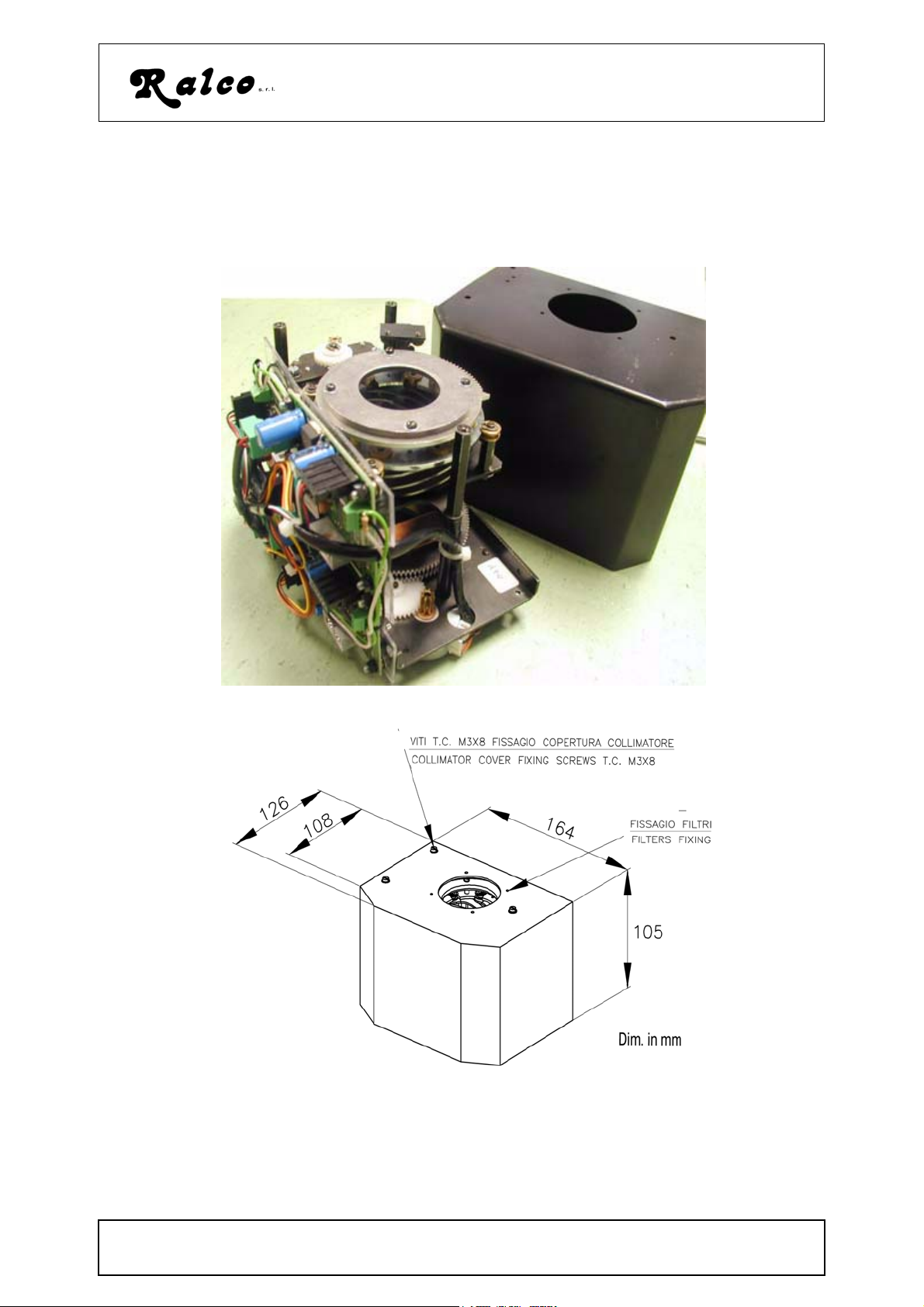
R605/025/DASM
without external interface board located between the collimator and the external analogical components and without second pair of rectangular shutters.
descrizione_605DASM.fm
MANUALE ISTRUZIONI / INSTRUCTIONS MANUAL
MTR605/025/DASM - R605/027/DASM - R605/170/DASM
B/ 4
Modello/Model R605DASM
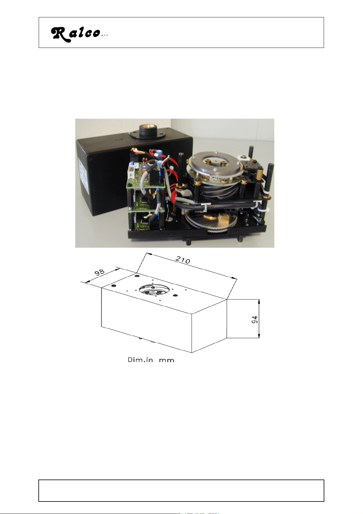
R605/027//DASM
without external interface board located between the collimator and the external analogical components and without second pair of rectangular shutters and with electronic
circuit on the short side of the collimator .
collimatori\605_027_DASM.gif
collimatori\dim_605_027_DASM.gif
descrizione_605DASM.fm
MANUALE ISTRUZIONI / INSTRUCTIONS MANUAL
MTR605/025/DASM - R605/027/DASM - R605/170/DASM
B/ 5
C - SPECIFICHE / SPECIFICATIONS
Filtrazione inerente in equivalente di alluminio :
Fascio radiogeno = 75 kV
EN 60601-1-3 par. 29.201.6 / 29.201.7
Inherent filtration Al. equivalent :
X-ray beam = 75 kV
EN 60601-1-3 par. 29.201.6 / 29.201.7
Limitazione Radiazione Extra-focale :
Distanza focale prevista, D.F.F. 1 m
EN 60601-1-3 par.29.202.3
Limitation of Extra focal radiation:
Set focus distance, FFD (SID) 1 m
EN 60601-1-3 par.29.202.3
Campo radiogeno quadro selezionabile:
1 m D.F.F - (± 1% FFD - SID)
EN 60601-1-3 par. 29.202.4
Square X-ray field selection :
1 m FFD (SID ) - (± 1% FFD - SID)
EN 60601-1-3 par. 29.202.4
Campo radiogeno tondo selezionabile:
1 m D.F.F - (± 1% FFD - SID)
EN 60601-1-3 par. 29.202.4
Round X-ray field selection :
1 m FFD (SID ) - (± 1% FFD - SID)
EN 60601-1-3 par. 29.202.4
Indicatore luminoso di campo - luminosità:
Luminosità a 1m dal fuoco, campo impostato 35 x
35 cm , Lampada alimentata a 24V, conduttori da
1.5mm
EN 60601-1-3 par. 29.202.7
Light field indicator - luminosity:
luminosity at 1 m from the focus, set field size
35x35 cm, 24V lamp supply, 1.5mm leads
EN 60601-1-3 par. 29.202.7
Indicatore luminoso di campo- contrasto:
Contrasto ai bordi impostando 35x 35 cm a 1m dal
fuoco
EN 60601-1-3 par. 29.202.7
Light field indicator - contrast:
edge contrast setting 35x35 cm at 1 m FFD (SID)
EN 60601-1-3 par. 29.202.7
Precisione dell’indicatore luminoso di campo:
Corrispondenza con il campo radiogeno
EN 60601-1-3 par. 29.202.9
Light field indicator precision:
Light field/x-ray field correspondence
EN 60601-1-3 par. 29.202.9
Specif_605.fm
Modello/Model R605DASM
Min. Al 0mm
< 150 mm
n.a.
n.a.
Min. <5cm diam.
Max. 30 cm
Lamelle rettangolari
Rectangular shutters
Min. 00 cm
Max. 30 cm
n.a.
n.a.
n.a.
MANUALE ISTRUZIONI / INSTRUCTIONS MANUAL
MTR605/025/DASM - R605/027/DASM - R605/170/DASM
C/ 1
Precisione dell’indicazine di campo RX:
Impostazione indice su scala graduata
EN 60601-1-3 par. 29.202.8
X-ray field indication precision:
Settings on an index scale
EN 60601-1-3 par. 29.202.8
Distanza fuoco ricettore : (optional)
Precisione indicazione con metro retraibile
EN 60601-1-3 par. 29.203.2
FDD (SID): (optional)
Precision of measurement with retractable tape
EN 60601-1-3 par. 29.203.2
Radiazione di fuga:
Misurata a 100 cm dal fuoco con fascio radiogeno =
125 kVp / 4 mA - EN 60601-1-3 par. 29.204.3
Leakage radiation :
Measured at 100 cm with x-ray beam = 150 kVp / 4
mA - EN 60601-1-3 par. 29.204.3
Alimentazione lampada:
Power supply, lamp :
Modello/Model R605DASM
n.a.
n.a.
< 40 mRh
n.a.
Alimentazione motori:
Power supply for motors:
Fusibile:solo su scheda ASR003 - rapido.
L’alimentazione deve essere protetta di una fusibile
non fornito.
Fuse:on ASR003 only - rapid. Supply must be
protected by a fuse which is
Lampada / Lamp
Filtrazione Aggiuntiva: 20 mm AL. equivalent
Filtration, Additional
Potenziometri:
Potentiometers:
Portata massima delle guide porta-accessori
not provided.
Campo quadro
Campo tondo
Square field
Round field
24V DC
3,15 Amp
Ritardato Certificato
Delayed Certified
n.a.
Lamelle in rame spessore/thick
copper shutters:
Test: 75kVp-50 mA - 0,3 sec.
n.a.
1 turn/giro 1Kohm
n.a.
1 turn/giro 1Kohm
n.a.
1 mm
Maximum load for accessory guides
Utilizzo del collimatore:
Specif_605.fm
MANUALE ISTRUZIONI / INSTRUCTIONS MANUAL
MTR605/025/DASM - R605/027/DASM - R605/170/DASM
n.a.
Sistemi di fluoroscopia mobili
C/ 2
Modello/Model R605DASM
Collimator operation:
Dotazione Standard:
Items included with the collimator
Peso/ Weight
Mobile fluoroscopy systems
- Manuale Istruzioni
- Instructions Manual
1,6 Kg
NB: per campi inferiore, 9” e 7” è necessario sostituire il collimatore secondario.
Pertanto all’ordine è indispensabile specificare il campo richiesto.
NB: the secondary collimator needs to be substitute if smaller fields, 9” and 7”, are
required. Please specify this requirement in your order.
Specif_605.fm
MANUALE ISTRUZIONI / INSTRUCTIONS MANUAL
MTR605/025/DASM - R605/027/DASM - R605/170/DASM
C/ 3
Modello/Model R605DASM
Validation of specification data:
• Validation of minimum filtration of the radiation unit (x-ray tube, collimator and possible filters) must be performed on a completely installed system by whoever is
responsible for the installation.
• Validation of light field luminosity and contrast is performed in-factory. See Chapter
COMPLIANCE VERIFICATION.
• Validation of system x-ray leakage is to be performed following the installation of
the system components under the responsibility of the person performing the installation.
• The correct installation of the system, electronic calibration and wiring layout of the
same are the responsibility of the engineer responsible for the installation of the
system.
• Protection of the cable is to be provided by the installation engineer.
Ralco is prepared to provide any information required regarding the validation methods
described above.
Classification
WARNING
GUIDES FOR ACCESSORIES PRIOR TO INSERTING ACCESORIES IN THE
GUIDES CHECK ON THE PERFECT FIT OF THE SUPPORT WITH THE MOUNTING
SLOT ON THE COLLIMATOR (TOLERANCE MAX. ± 0,5 MM). A FAULTY FIT COULD
BE DANGEROUS AND IT COULD CAUSE THE FALL OF ACCESSORIES
EN 60601-1 par. 5
• Protection against electric hazards: "Class I" equipment
• Protection against direct and indirect contacts: Type B equipment with applied
parts.
• Protection against water see page: "Common equipment"
• Safety of operation in the presence of inflammable anaesthetics with air or oxygen
or nitrous oxide: Equipment not suited to application in the presence of inflammable
anaesthetic mixtures containing air o oxygen of nitrous oxide.
• Operation conditions: Equipment for continuous operation at intermittent loads See Chapter OPERATION INSTRUCTIONS.
• Should label data on the collimator not correspond to the specifications herein,
inform Ralco of the non conformity.
• Verifications of the specifications are to be performed according to the indicated
equipment standards.
Operation environment:
• Ambient temperature = from 10°C to 40°C
• Relative Humidity = from 30% to 75%
• Atm. Press. = from 700 to 1060 hPa.
verifica_spec.fm
MANUALE ISTRUZIONI / INSTRUCTIONS MANUAL
MTR605/025/DASM - R605/027/DASM - R605/170/DASM
C/ 4
Modello/Model R605DASM
per collimatori dotati di metro for collimators with tape measure
AVVISO WARNING
Uso del metro retraibile in collimatori
dotati di questa funzione:
Il metro adottato è un metro standard
montato su apparecchiatura radiologica.
In questa applicazione il metro parte con
la misurazione con un valore che
corrisponde alla distanza fuoco/ bordo
inferiore del collimatore; la massima
estensione radiologica è di 2m max
anche se, per ragioni meccaniche, il
metro raggiunge 3 m max. A fine lettura
meccanica massima viene riportata la
scritta STOP.
Estendere e/o forzare il nastro del metro
oltre a questa misura causa i seguenti
inconvenienti:
• rottura del nastro oppure
• distorsione del nastro oppure
• l'impossibilità di fare rientrare il nastro
nell'alloggiamento perché è stata forzata la tenuta della molla sul nastro
creando una distorsione.
NOTA: NON ESTENDERE IL NASTRO
OLTRE Il NECESSARIO E IN OGNI CASO
NON OLTRE LA SCRITTA STOP
Use of the retactable tape measure in
collimators with this feature:
The type of tape measure adopted is a
standard tape mounted on a
radiological unit. In this application the
tape starts with values that correspond
to the focus/collimator lower edge
distance; maximum radiological
measurement with the tape is 2 m max
even though, for purely mechanical
reasons, maximum tape extension is 3
m max. The indication of STOP is
evident immediately after the maximum
mechanical value.
Forcing and/or extending the tape
beyond this point with cause the following inconveniences:
• Breakage of the tape or,
• Distortion of the tape or,
• Impossibility of retracting the tape
into its lodging because the grip of
the spring has been forced and
hook-up is consequently distorted.
NOTE: DO NOT EXTEND THE TAPE
BEYOND THE INDICATION OF STOP
EN 60601-1-3 para. 29.205 - Focus-Skin Distance
Paragraphs 29.205.1 - 29.205.3 of the above standard deal with preventing the use of
inappropriate focus/skin distances in order that the dose equivalent to the patient be
kept as low as reasonably achievable.
29.205.1 - Radiation Equipment for fluoroscopy
X-ray devices for fluoroscopy must feature characteristics that, during fluoroscopy, will
prevent focus-skin distances less than:
• 20 cm if the x-ray device is specifically for fluoroscopy
• 30 cm for other applications
Conformity is measured and checked visually. The x-ray system must comply with the
norm; this means that the operator is responsible for the verification. A focus/skin spacer device is an option made available by Ralco.
verifica_spec.fm
MANUALE ISTRUZIONI / INSTRUCTIONS MANUAL
MTR605/025/DASM - R605/027/DASM - R605/170/DASM
C/ 5
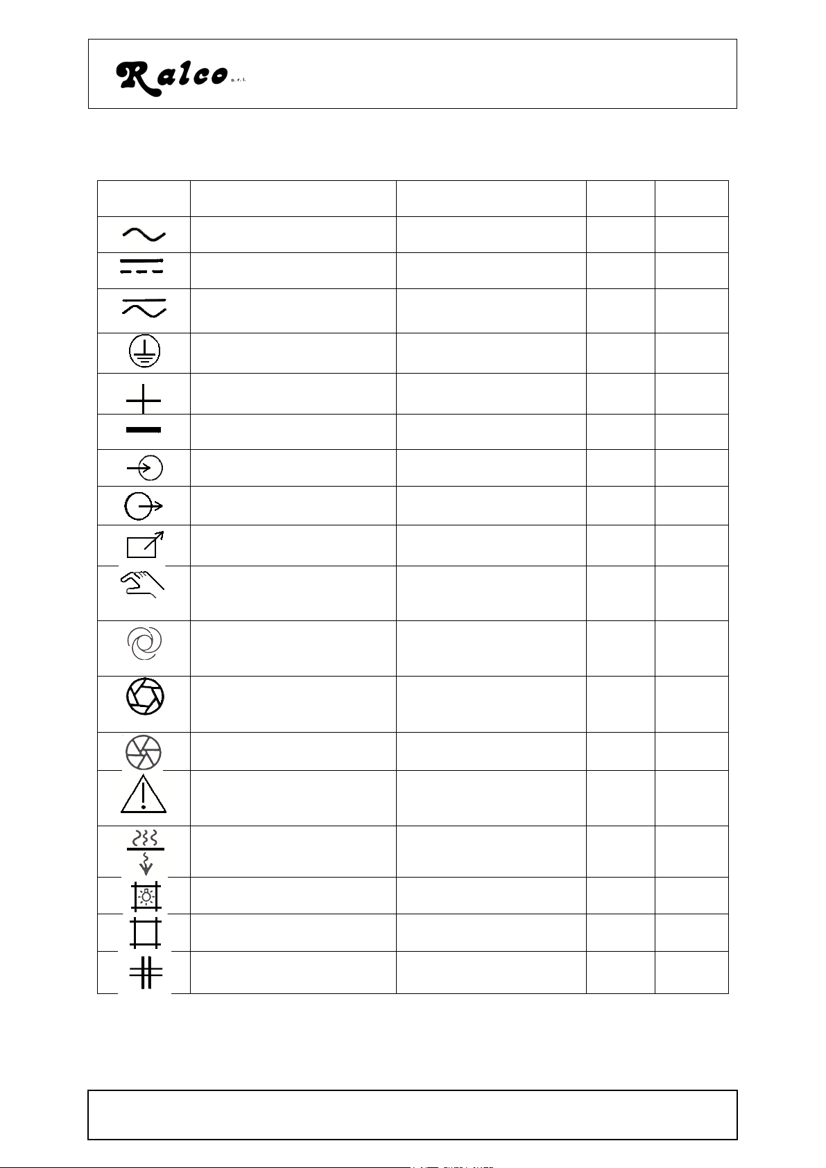
D - SIMBOLI/SYMBOLS
Modello/Model R605DASM
Simboli/
Symbols
Descrizione Description no. Rif.CEI
Corrente Alternata Alternating Current 01-14 417-IEC
503
Corrente Continua Direct current 01-18 417-IEC
5031
Corrente continue e Alternata
Both Direct and alternating current
01-19 417-IEC
5033
Terra di protezione Protective earth 01-20 417-IEC
5019
Più; polarità positiva Plus; positive polarity 01-27 417-IEC
5019
Meno; polarità negativa Minus; negative polarity 01-28 417-IEC
5006
Entrata Input 01-36 417-IEC
5006
Uscita Output 01-37 417-IEC
5034
Controllo a distanza Remote Control 01-38
Controllo manuale Manual control 01-45 ISO
7000096
Controllo automatico Automatic control
(closed loop)
01-46 ISO
70000017
Diaframma a iride aperto Iris Diaphragm: open 01-69 ISO
70000017
Diaframma a iride: chiuso Iris Disaphragm: closed 01-70 417-
5324
Attenzionne, consultare i
documenti di accompagnamento
Filtro di radiazione oppure
filtrazione
Attention: Consult
accompanying documents
Radiation filter or filtration
03-02
04-51 417-
IEC 601-
1
5381
IEC
IEC
Indicatore luminoso del
campo di radiazione
Dispositivo di limitazione
fascio: aperto
Dispositivo di limitazione
fascio: chiuso
simboli.fm
MANUALE ISTRUZIONI / INSTRUCTIONS MANUAL
MTR605/025/DASM - R605/027/DASM - R605/170/DASM
Light indicator of radiation field
Beam limiting device:
open
Beam limiting device:
closed
04-51 417-IEC
5381
04-55 417-IEC
5385
04-56 417-IEC
5386
D/ 1
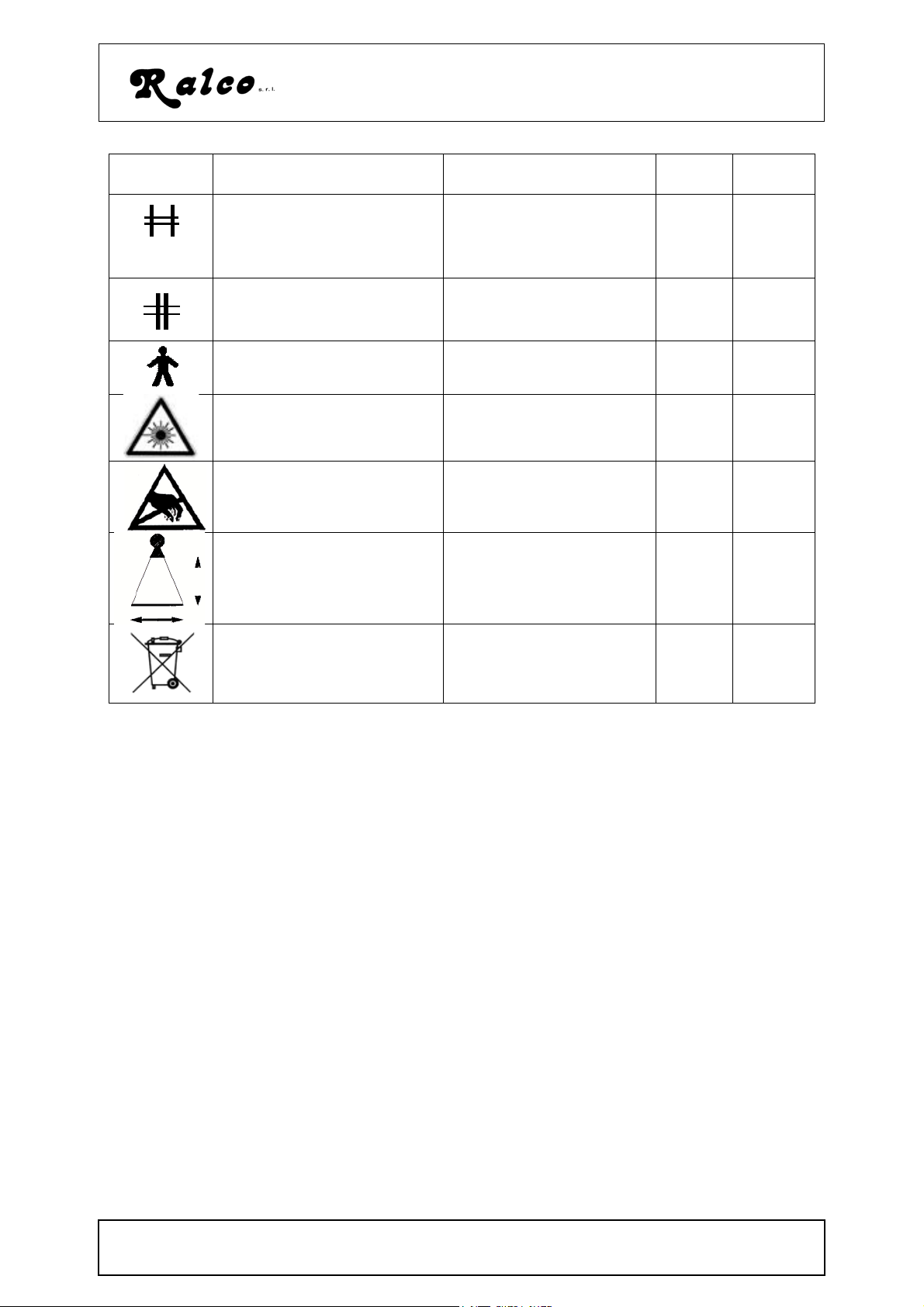
Modello/Model R605DASM
Simboli/
Symbols
Descrizione Description no. Rif.CEI
Dispositivo di limitazione
fascio:chiuso con apertura separata della
Beam limiting device:
closed with separate
opening of the shutters.
04-57 417-IEC
5387
lamelle.
Dispositivo di limitazione
fascio con chiusura separata della lamelle.
Beam limiting device
with with separate closing of the shutters
04-58 417-IEC
5388
Apparecchio tipo B Type B device 02-02 601-I-
IEC
Attenzione radiazione
Laser
Dispositivo sensibile
all’energia elettrostatica.
Dispositivo impostazione
dimensione cassetta
Caution: Laser Radiation
Electrostatic sensitive
device.
Cassette size sensing
device.
60825-1
Dispositivo che richiede
un corretto smaltimento.
Device requiring proper
disposal.
attch.4 2002/
95/CE
simboli.fm
MANUALE ISTRUZIONI / INSTRUCTIONS MANUAL
MTR605/025/DASM - R605/027/DASM - R605/170/DASM
D/ 2
Modello/Model R605DASM
E - COMPATIBILITY WITH X-RAY TUBES:
a) Compatibility between the collimator and x-ray tube is determined by the
mechanical possibility of mounting them - See the following Table.
b) Collimator R605DASM has no inherent filtration. Check that the tube housing litera-
ture indicates congruent minimum inherent filtration (1mm or 0mm) and, that maximum radiation leakage is 30 mr/hour measured at one meter from the source when
operating at its leakage technique factors (125 at 4 mA).
c) Source values (tube housing-collimator) must not be less than 3mm Al for filtration
and must never exceed 100 mR/hr for radiation leakage. (EN 60601-1-3 par.
29.201.7/29.201.6 e 21 CFR sub-chapter J, part 1020.30 (m) (1).
d) The distance between the tube x-ray focus and the flange mounting plane (collimator
upper plate) must be 80 mm (3.14"), tollerance +/- 1mm (0.04”).
Table 1:
Collimators
R72
R103
R104
R105
generali\r72_cufie.gif
compatibilità_tubo.fm
MANUALE ISTRUZIONI / INSTRUCTIONS MANUAL
MTR605/025/DASM - R605/027/DASM - R605/170/DASM
generali\cuffie_104.gif
E/ 1
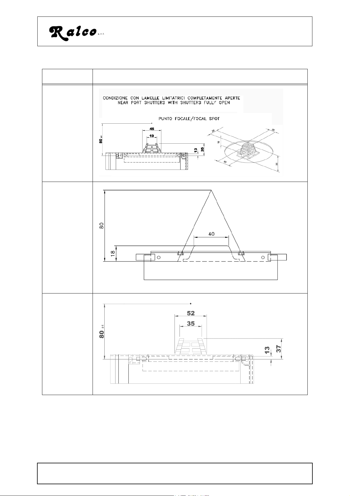
Table 1:
g
Collimators
R104/A
Modello/Model R605DASM
collimatori\104A\cuffie_104_177_A.
R107
R108
collimatori\107\comp_tubo
generale\108_cuffie
compatibilità_tubo.fm
MANUALE ISTRUZIONI / INSTRUCTIONS MANUAL
MTR605/025/DASM - R605/027/DASM - R605/170/DASM
E/ 2
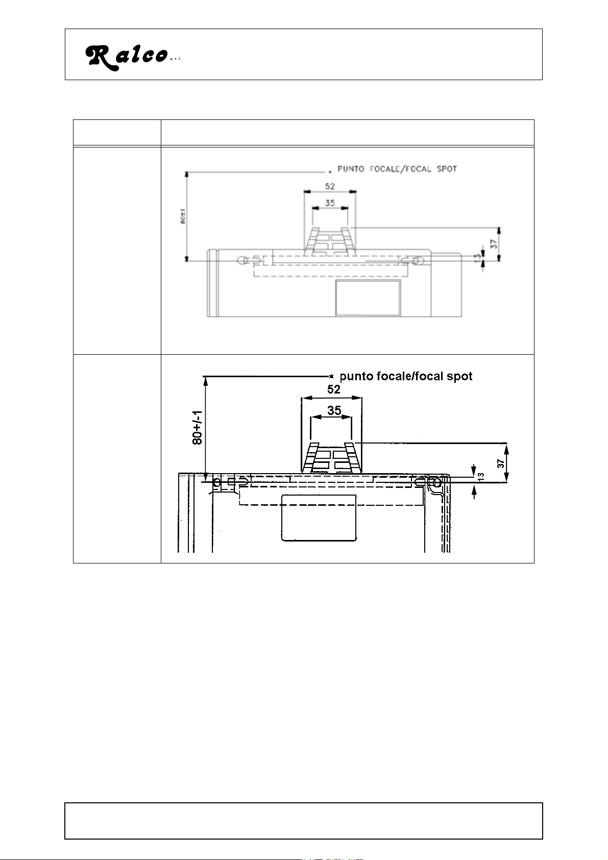
Table 1:
Collimators
R302/A
R302F/A
R302L/A
R302DACS/A
R302MLP/A
R302MLPI/A
R503MLP/A
Modello/Model R605DASM
generali\06_compt_manuali
R221/A
general\compt_manuali221
compatibilità_tubo.fm
MANUALE ISTRUZIONI / INSTRUCTIONS MANUAL
MTR605/025/DASM - R605/027/DASM - R605/170/DASM
E/ 3
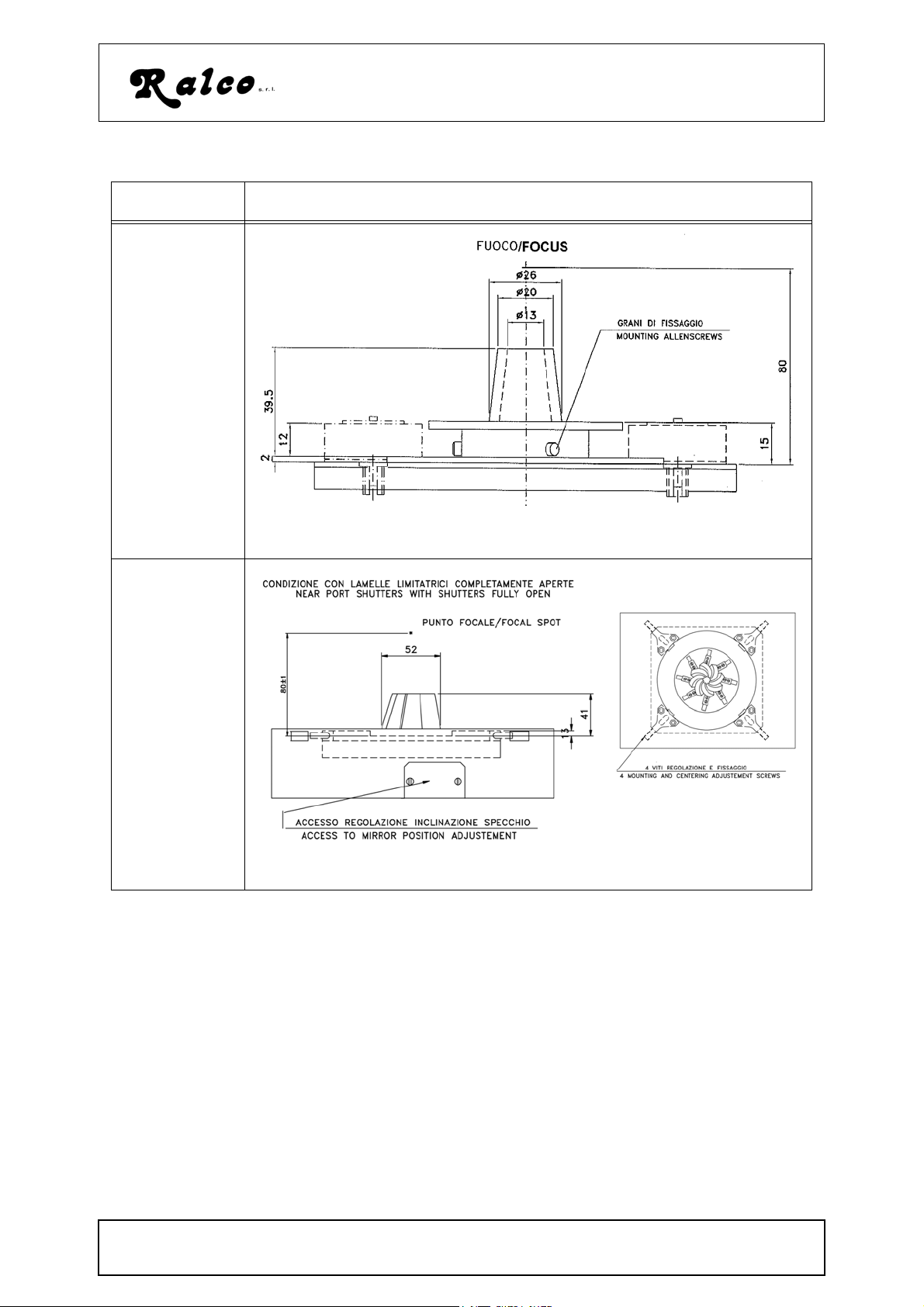
Table 1:
Collimators
R605DASM
Modello/Model R605DASM
R806D
collimatori\605\compta_tubo_fig1.gif
collimatori\806\tubo_R806D.gif
compatibilità_tubo.fm
MANUALE ISTRUZIONI / INSTRUCTIONS MANUAL
MTR605/025/DASM - R605/027/DASM - R605/170/DASM
E/ 4

Modello/Model R605DASM
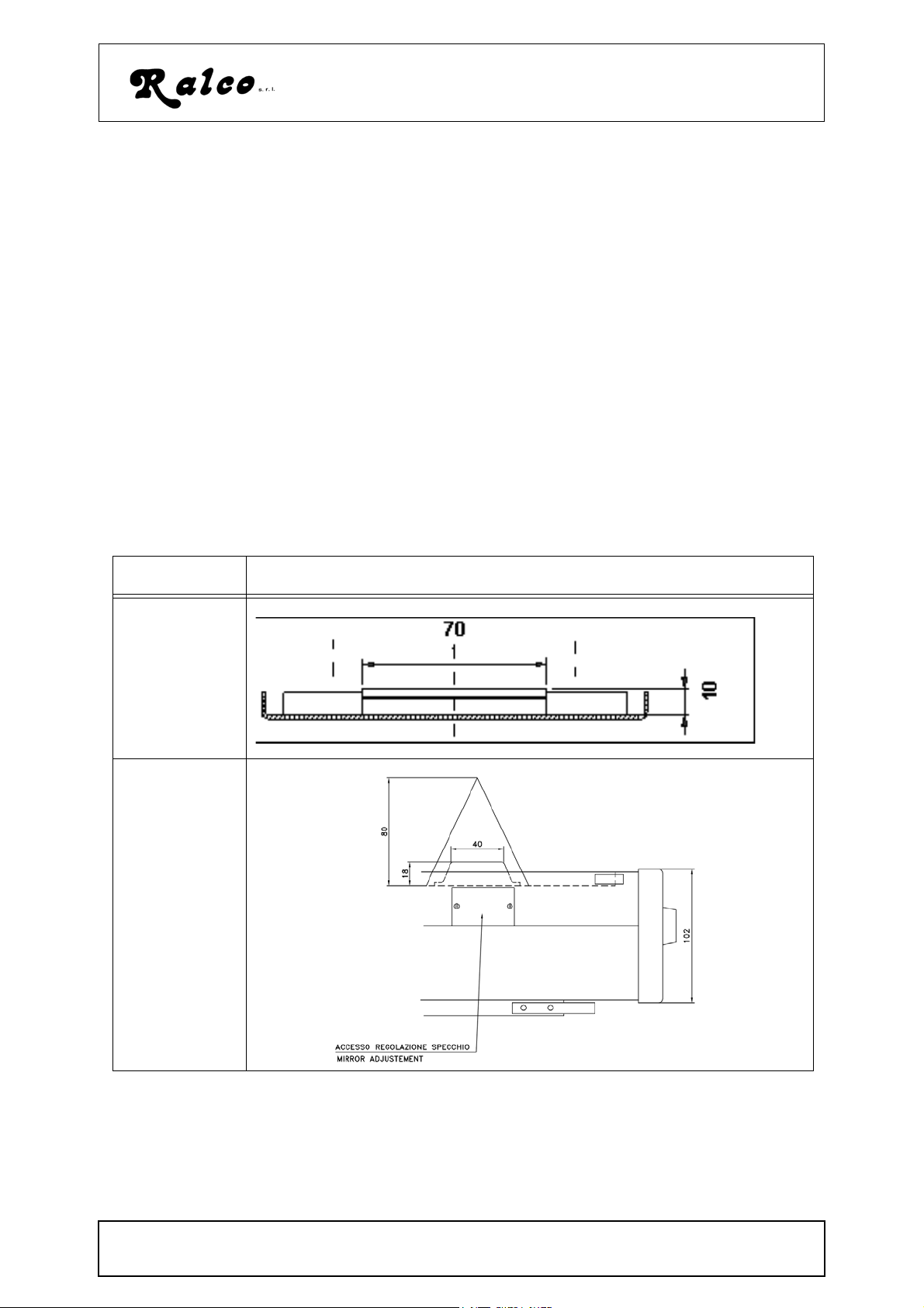
F - MOUNTING THE COLLIMATOR TO THE X-RAY TUBE
WARNING:
CAREFULLY FOLLOW THE MOUNTING INSTRUCTIONS AND MAKE SURE THAT
THE COLLIMATOR IS CORRECTLY ASSEMBLED. INCORRECT MOUNTING
COULD BE DANGEROUS: IT COULD CAUSE THE COLLIMATOR TO FALL OR TO
OPERATE INACCURATELY
a) Determine the distance from the focal spot to the tube port face from the X-ray tube
housing literature
b) Subtract the resulting distance from 80 mm. (3.15") and determine how many 1.5
mm (0,06") spacers combined with the thickness of the mounting flange will make
up the difference (15mm for the flange). Allowable tolerance is 1 mm. (0.04")
c) Carefully match the flange with the tube and make sure that the brass cone on the
mounting flange is free from impediments on the side of the housing.
d) Select four bolts of suitable thread (M4 ) and of such a length that they protrude
through the flange and spacers far enough to engage at least 5 threads into the tube
port face. Securely bolt the flange to the tube port face..
IMPORTANT
SAFEGUARD THE OPERATOR AND PATIENT AGAINST THE HAZARD OF A
TO
FALLING COLLIMATOR, THE FOLLOWING INDICATIONS ARE TO BE RESPECT-
ED.
e) Unscrew, but not remove, the three mounting Allen screws on the collimator metal
ring. See Figure 1 in this Chapter
f) Fit the metal ring on the collimator over the mounting flange and tighten the screws.
montag_coll-tubo.fm
MANUALE ISTRUZIONI / INSTRUCTIONS MANUAL
MTR605/025/DASM - R605/027/DASM - R605/170/DASM
F/ 1
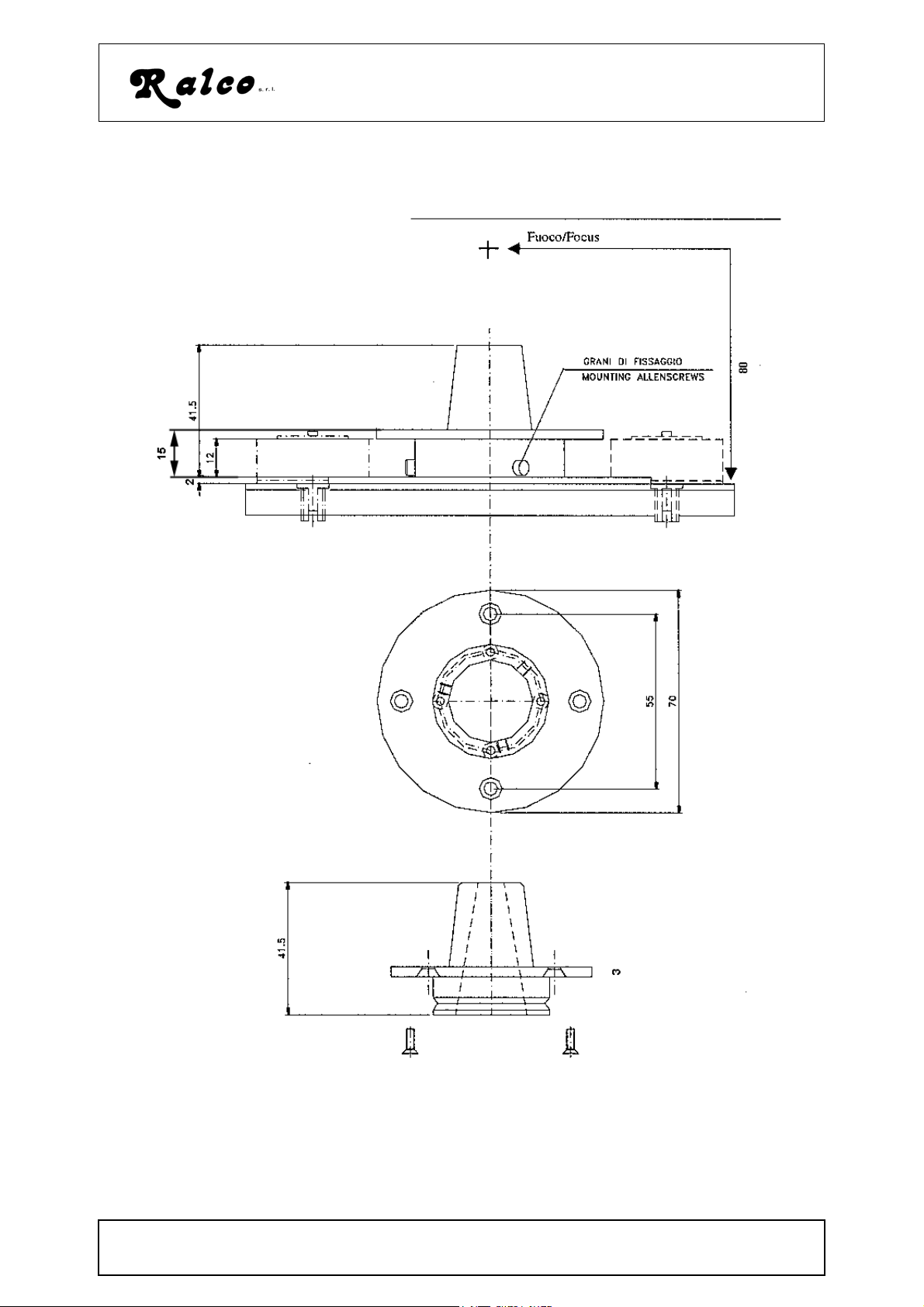
Figura 1
collimatori\605\montaggio
tubo
fig1
gif
Modello/Model R605DASM
.
_
_
montag_coll-tubo.fm
MANUALE ISTRUZIONI / INSTRUCTIONS MANUAL
MTR605/025/DASM - R605/027/DASM - R605/170/DASM
F/ 2
Modello/Model R605DASM
MECHANICAL INSTALLATION OF THE EXTERNAL INTERFACE UNIT:
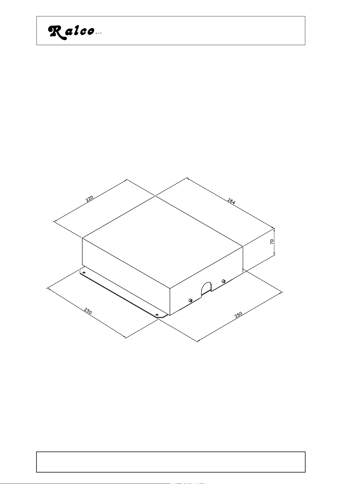
The external box is to be installed in such a way as to ensure connection of all the electric devices present in the radiological system.
We suggest that the box be installed at a safe distance from electromagnetic sources
such as high voltage transformers.
Use the holes on the sides of the box to perform the installation.
Should it be necessary to install the back within a rack of the general system, remove
the electronic board from the box prior to proceeding with the installation of the box itself.
Make sure that each portion of the rack that is to accommodate the box is adequately
earthed.
collimatori\dacs\scat_esterna_dac.gif
installazione_mecc_pt2.fm
MANUALE ISTRUZIONI / INSTRUCTIONS MANUAL
MTR605/025/DASM - R605/027/DASM - R605/170/DASM
F/ 3
Modello/Model R605DASM
G - COLLEGAMENTO ELETTRICO/ELECTRIC CONNECTION
ATTENZIONE
L
’ALIMENTAZIONE SUL COLLIMATORE NON È PRO-
TETTO DA FUSIBILE. PRIMA DI COLLEGARE, CON-
TROLLARE CHE L’ALIMENTAZIONE SIA PROTETTA
DA FUSIBILE ESTERNO.
FUSIBILE: 3,15 AMP
Collegamento/Connection R605 DASM:
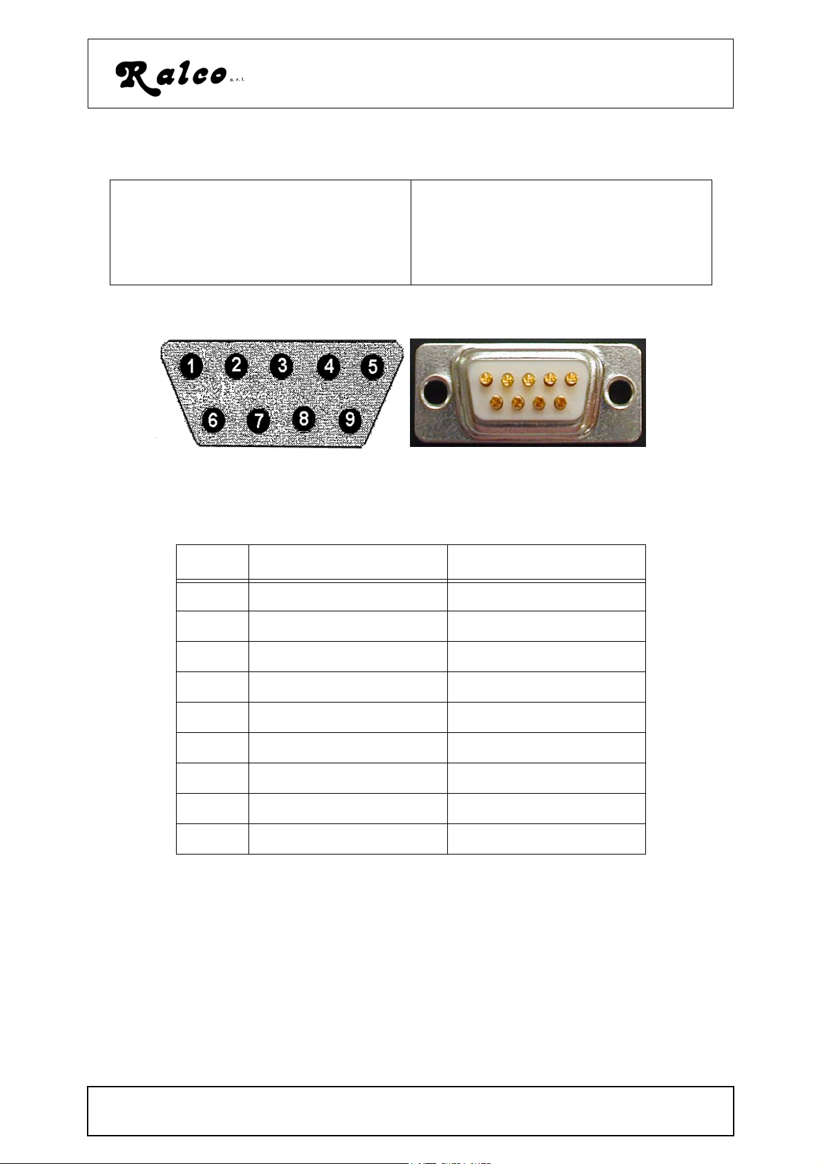
Table 1: 9 pin (male) D-Sub CAN Bus PinOut
Pin n. Signal Names Signal Description
WARNING
COLLIMATOR
FUSE. PRIOR TO CONNECTING THE UNIT CHECK
THAT SUPPLY IS PROTECTED BY AN EXTERNAL
FUSE.
FUSE: 3,15 AMP
SUPPLY IS NOT PROTECTED BY A
collimatori\605\connett
1
2 CAN_L Dominant Low
3 CAN_GND Ground
4
5
6 GND (24 AC) Ground
7 CAN_H Dominant High
8
9 CAN_V+ (24 AC) Power
coll_ell.fm
MANUALE ISTRUZIONI / INSTRUCTIONS MANUAL
MTR605/025/DASM - R605/027/DASM - R605/170/DASM
G/ 1
Modello/Model R605DASM
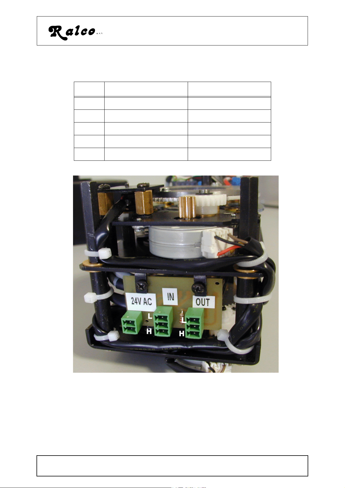
Table 2: R605/027/DASM
Pin n. Signal Names Signal Description
1 24 VAC Supply
2 24 VAC Supply
1 CAN_L Dominant Low
2 CAN_GND Ground
3 CAN_H Dominant High
coll_ell.fm
MANUALE ISTRUZIONI / INSTRUCTIONS MANUAL
MTR605/025/DASM - R605/027/DASM - R605/170/DASM
.images/colliamtori/605/coll_ell_fig4
G/ 2
Modello/Model R605DASM
H - ELECTRICAL POWER CONNECTION OF THE EXTERNAL UNIT TO THE GENER-
AL SYSTEM
WARNING: THE SYSTEM MUST BE SUPPLIED BY 24VAC +/-
10%. A
MOTOR CONTROL ELECTRONICS
:
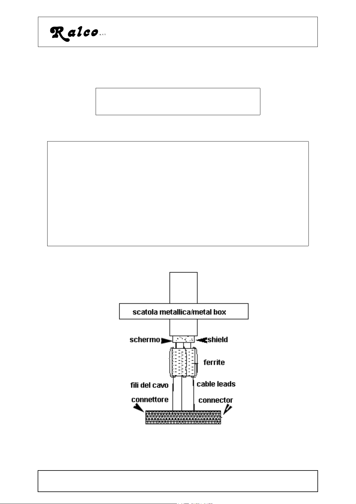
WARNING
PRIOR TO CONNECTING THE COLLIMATOR CHECK THAT SUPPLY IS PROTECTED BY AN EXTERNAL
FUSE 6,3A (SEE THE SPECIFICATIONS).
CABLES (24VAC) USED FOR COLLIMATOR CONNECTION MUST BE SUITABLE FOR PURPOSE AND
COLLIMATOR CURRENT ABSORPTION.(MIN. SECTION 1.5MM2)
THE SYSTEM REQUIRES SCREENED CABLES WITH THE ADDITION OF FERRITE CORES TO AVOID
INTERFERENCE OF ELECTROMAGNETIC DISTURBANCES WITH THE SERVER ELECTRONICS.
CABLES FROM THE SYSTEM TO THE EXTERNAL BOARD MUST BE SCREENED.
THE FERRITE CORES ARE TO BE MOUNTED ON THE CABLES INSIDE THE BOX AS SHOWN IN THE
DRAWING BELOW. FERRITE CORES ARE USED TO ATTENUATE INDUCTION AND IRRADIATION OF
ELECTROMAGNETIC INTERFERENCE.
WE SUGGEST A 279 FERRITE, ATTENUATION RANGE 100 MHZ TO 200 MHZ, SUITED TO YOUR
CABLES; EG: MSFC-10 FERRITE BY RICHCO
NY VOLTAGE IN EXCESS WILL DAMAGE STEPPER
images\collimatori\acs\ferrite.gif
elettr_302_ACSdhhs.fm
MANUALE ISTRUZIONI / INSTRUCTIONS MANUAL
MTR605/025/DASM - R605/027/DASM - R605/170/DASM
H/ 1
 Loading...