


 Loading...
Revision: G
Version: May 26, 2010
File: [201175-F-01-01.doc]
User’s Manual
WARNING: The information that is printed within this manual is vital for the correct use of the equipment; please read it carefully before use.

User's Manual |
ARCOVIS 3000 S/R |
Villa Sistemi Medicali |
This page is intentionally left blank
[File:201175-G-01-01.doc]

Villa Sistemi Medicali ARCOVIS 3000 S/R User's Manual
Table of contents
1. |
SAFETY AND COMPLIANCE ........................................................................................................... |
2 |
|
|
1.1. |
Electrical safety ............................................................................................................................................. |
3 |
|
1.2. |
Laser targeting devices safety ...................................................................................................................... |
3 |
|
1.3. |
Mechanical safety ......................................................................................................................................... |
3 |
|
1.4. |
Electromagnetic compatibility (EMC) ............................................................................................................ |
4 |
|
1.5. |
Protection against ionizing radiation ............................................................................................................. |
4 |
|
1.6. |
General disposal ........................................................................................................................................... |
5 |
|
1.7. |
Interfaceability ............................................................................................................................................... |
5 |
|
1.8. |
Copyright....................................................................................................................................................... |
5 |
|
1.9. |
Application and final destination.................................................................................................................... |
6 |
|
1.10. |
Classification ................................................................................................................................................. |
7 |
|
1.11. |
List of the Standards for the evaluation of the product compliance .............................................................. |
7 |
|
1.12. |
Compliance ................................................................................................................................................... |
7 |
2. |
COMPONENT IDENTIFICATION ...................................................................................................... |
8 |
|
|
2.1. |
Overview ....................................................................................................................................................... |
8 |
|
2.2. |
Mobile Stand ............................................................................................................................................... |
10 |
|
2.3. |
Keyboard..................................................................................................................................................... |
12 |
|
2.4. |
Fluoroscopy control footswitch.................................................................................................................... |
18 |
|
2.5. |
Handswitch for radiography / fluoroscopy control ....................................................................................... |
18 |
|
2.6. |
Monitor Trolley ............................................................................................................................................ |
19 |
|
2.7. |
Operative messages ................................................................................................................................... |
20 |
|
2.8. |
Alarm messages ......................................................................................................................................... |
21 |
|
2.9. |
Safety devices............................................................................................................................................. |
23 |
3. |
UNIT USE......................................................................................................................................... |
24 |
|
|
3.1. |
Transport..................................................................................................................................................... |
24 |
|
3.2. |
Connection between monitor trolley – mobile stand ................................................................................... |
25 |
|
3.3. |
Connection between Footswitch – Mobile Stand ........................................................................................ |
26 |
|
3.4. |
Unit ON / OFF ............................................................................................................................................. |
27 |
|
3.5. |
Positioning................................................................................................................................................... |
29 |
|
3.6. |
Use mode.................................................................................................................................................... |
30 |
|
3.7. |
Shutdown procedure ................................................................................................................................... |
40 |
4. |
MAINTENANCE............................................................................................................................... |
41 |
|
|
4.1. |
General warnings ........................................................................................................................................ |
41 |
|
4.2. |
Checks and inspection by the user ............................................................................................................. |
41 |
|
4.3. |
Cleaning ...................................................................................................................................................... |
42 |
|
4.4. |
Disinfection.................................................................................................................................................. |
42 |
5. |
TECHNICAL DATA.......................................................................................................................... |
43 |
|
|
5.1. |
Labels and symbols .................................................................................................................................... |
43 |
|
5.2. |
Environmental conditions ............................................................................................................................ |
47 |
|
5.3. |
Electrical data.............................................................................................................................................. |
48 |
|
5.4. |
Exposure mode: fluoroscopy....................................................................................................................... |
58 |
|
5.5. |
Exposure mode: radiography ...................................................................................................................... |
61 |
|
5.6. |
Image system.............................................................................................................................................. |
62 |
|
5.7. |
Digital image processor............................................................................................................................... |
65 |
|
5.8. |
Accessories................................................................................................................................................. |
70 |
6. |
MECHANICAL DATA ...................................................................................................................... |
73 |
|
|
6.1. |
C-arm unit dimensions with I.I. 9”............................................................................................................... |
73 |
|
6.2. |
Axis and interventionist reference point ...................................................................................................... |
73 |
|
6.3. |
“Base Trolley” monitor trolley dimensions ................................................................................................... |
74 |
|
6.4. |
Dimensions of “High Configuration” monitor trolley..................................................................................... |
75 |
|
6.5. |
Mechanical data, dimensions and weights.................................................................................................. |
76 |
7. |
DOCUMENT STATUS ........................................................................................................................ |
I |
|
[File:201175-G-01-01.doc] |
Rev. A - Pag. 1/76 |
User's Manual |
ARCOVIS 3000 S/R |
Villa Sistemi Medicali |
1. SAFETY AND COMPLIANCE
The purpose of this user's manual is to provide a set of easy to use instructions for the proper use of the system. All of the information contained herein is based on the current version of the system. Villa Sistemi Medicali reserves the right to improve and implement changes to the information herein to reflect any changes necessitated by technological enhancements to the system.
This x-ray unit must be used in strict compliance with the safety instructions contained in this manual and must not be used for purposes other those for which it was intended.
The x-ray unit may only be operated by skilled, properly trained personnel with the required knowledge of x-ray safety practices and the proper use of x-ray equipment.
The operator is responsible for the use of the system in compliance with the applicable standards concerning installation and use.
The system safety circuits and devices must not, for any reason, be moved, modified, or omitted.
The monitor trolley key switch may only be activated by authorized personnel and only during the use of the system. Once system use has been completed, the key must be removed and stored in a safe place.
The unit must not be operated when electrical, mechanical, or radiological faults are present or when any of the indicators or alarm devices are malfunctioning.
When used in conjunction with other apparatus, components, or modules, whose compatibility is uncertain, it is necessary to ensure the absence of any danger to the patient or operator. Consult Villa Sistemi Medicali for information.
As with any technical apparatus, this x-ray unit must be used properly with periodic checks and maintenance as specified in the chapter “Planned maintenance” of the Service Manual.
Villa Sistemi Medicali is responsible for the safety of its products only when maintenance, repairs, or modifications have been performed by its personnel or by personnel authorized by Villa Sistemi Medicali in writing.
Villa Sistemi Medicali cannot be held liable for any malfunction, damage, or danger resulting from improper use of the system or non-compliance with the rules for proper maintenance.
Pag. 2/76 - Rev. A |
[File:201175-G-01-01.doc] |
Villa Sistemi Medicali |
ARCOVIS 3000 S/R |
User's Manual |
1.1. Electrical safety
Only trained service personnel authorized by Villa Sistemi Medicali may remove the unit covers and only in accordance with the instructions contained in the Service Manual.
This x-ray unit may only be used in environments or medical rooms in compliance with the applicable IEC standards.
The x-ray unit must not be used in areas where there exists a danger of explosion.
Cleaning and disinfecting agents, including those used on patients, may create an explosive, gaseous mixture. Use only those products in compliance with the applicable rules.
1.2.Laser targeting devices safety
•Keep always a good lightening on the room.
•Never look through the output window of the laser targeting device.
•Never fix the reflections of the laser targeting devices.
•Before starting any examination, the patient must remove earrings, glasses, necklaces and whatever could reflect the laser beam and be printed on the image.
•Don't clean the openings of the laser targeting devices with tools that could modify their optics. Only the service personnel must perform possible cleaning actions.
•The min. distance between the laser source and the patient must not be lower than cm20.
The only purpose of the laser use is to reduce the patient dose to a minimum, it doesn’t be considered as an absolute means of centering.
The activation of procedures other those listed above can cause the emission of dangerous non-ionizing radiations.
1.3. Mechanical safety
The unit can be moved only by trained personnel by complying with the following safety conditions:
•Move the unit by considering the conditions for the movement that are indicated in detail in the paragraph 3.1.
•Don't move and use the unit on surfaces with inclination higher than 5°
•Only use the proper handles to move the unit.
•Avoid collision with obstacles.
•After positioning the unit, engage the parking brakes.
[File:201175-G-01-01.doc] |
Rev. A - Pag. 3/76 |
User's Manual |
ARCOVIS 3000 S/R |
Villa Sistemi Medicali |
1.4. Electromagnetic compatibility (EMC)
This apparatus is in compliance with the standard IEC 60601-1-2 that defines the max. allowed emission levels from electronic devices and the required immunity from interference caused by externally generated electromagnetic fields.
It is not, however, possible to exclude radio signals coming from transmitters such as mobile phones or similar mobile radio devices. These and other transmitting devices, including those in compliance with the EMC standards, may influence the proper functioning of medical apparatus when used in proximity and with a relatively high transmitting power. Therefore, the use of radio equipment proximity to electronically controlled systems must be avoided in order to eliminate any interference risk.
Any transmissions by mobile radio equipment must be avoided. Mobile phones must be switched off in zones close to the unit.
These rules must be applied when the unit is switched on (that is to say connected to the mains and ready for use).
1.5. Protection against ionizing radiation
Before any x-ray exposure, ensure that all the necessary protective precautions have been taken.
During the use of x-rays, personnel present in the room must comply with the following rules concerning protection against ionizing radiation:
When necessary, use protective shielding against radiation in addition to the shielding already provided on the unit.
Use protective aprons containing a material equivalent to 0,35mm of lead. Material of this nature reduces radiation at 50kV by 99,95% and at 100kV by 94,5%.
The best protection against radiation is distance. It is therefore recommended that you stay as far as possible from the x-ray source and the exposure target. For this purpose, use all of the cable length provided for the foot-switch.
Avoid walking or standing directly in the x-ray beam.
Always use the smallest possible field of exposure by closing properly the collimator diaphragms. The scatter dose produced depends principally on the volume of the irradiated object.
Never modify or disconnect the safety circuits or devices designed to prevent accidental exposures.
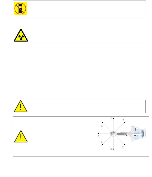
Collimation system adjusted to a field of 30 x 30 cm2 at 1 m from the x-ray tube focus. Exposure parameters: 100 kVp and 1 mA. Values normalized to 1 min. of fluoroscopy (µGy/min).
Equivalent water phantom 30x30x20cm.
The complete isodose measures are included into the report 035-07 ISO KERMA MAPPING (cod.200394) attached to the unit documentation
Pag. 4/76 - Rev. A |
[File:201175-G-01-01.doc] |
Villa Sistemi Medicali |
ARCOVIS 3000 S/R |
User's Manual |
1.6. General disposal
Villa Sistemi Medicali produces radiological systems that are advanced in terms of safety and environmental protection. Assuming that the unit is properly used, there is no risk to people or the environment.
In order to comply with applicable safety requirements, it is necessary to use materials that may be harmful to the environment (for example: monobloc oil, protective lead, monitor kinescope, boards and electronic components). Therefore, when necessary, proper disposal methods, according to the regulations of the country where the unit is installed, should be followed.
For this reason, the unit may not be disposed of along with industrial or domestic waste and must be regarded as hazardous waste.
This symbol indicates that the waste of electrical and electronic equipment must not be disposed as unsorted municipal waste and must be collected separately. The proper differentiated collection for the following start of the unit disused to the recycle, treatment and disposal, compatible with the environment, aid to prevent possible negative effects on the environment and health and it favours the recycle of materials that compose the unit.
The abusive disposal of the product from the user implies the application of administrative sanctions according to the Standards in force of the unit installation country.
For information concerning the dismantling modes of the units out of use, stick to the local provisions or contact a representative authorized by the manufacturer.
For additional information, contact Villa Sistemi Medicali.
1.7. Interfaceability
The device does not forecast any interaction with devices for medication.
It is possible to interface the unit with certain devices such as DVD Recorder, thermal printer, Network (DICOM System). Such devices must be in full compliance with the safety requirements specified by 93/42/EEC Directive. The liability of the interface, if it has not been evaluated and authorized by Villa Sistemi Medicali in writing, is of the operator and/or of the person who has performed this interface.
1.8. Copyright
The original release of this manual is in Italian language (file: 201175-C-01-00.doc). For further information, please refer to the Italian version.
The software contained in the unit belongs to Technix S.p.A.. Upon receipt of the unit, the user acquires the right to use the software. This right is neither exclusive nor transferable.
Written authorization to Technix S.p.A. is mandatory prior to any modifications for the unit use with functions other than the ones foreseen.
[File:201175-G-01-01.doc] |
Rev. A - Pag. 5/76 |

User's Manual |
ARCOVIS 3000 S/R |
Villa Sistemi Medicali |
1.9. Application and final destination
ARCOVIS 3000 S/R is a "mobile x-ray unit with image intensifier system" and it has been designed to be used for diagnosis. It must be operated exclusively by qualified, trained personnel who have been informed of the risks linked to the use of ionizing radiation.
The system does not belong to the category of equipment designed for continuous operation.
The system is not used in contact with the patient; however, accidental contact of some unit parts with the patient and the operator is possible.
Contact with the patient is non-invasive.
Contact with the operator is strictly for reasons linked to the use of the equipment (normal operation).
The unit is suitable to be used for x-ray examinations, and in particular for radioscopy, radiography and diagnosis dedicated to:
•Traumatology
•Pediatrics
•Simple interventional radiology
•Pace Maker implantation
•Operating theater
•Intensive care
•Respiratory system
•Skeletal structure
This x-ray unit must not be used in areas where danger of explosion exists.
For use in operating theater, it is necessary to use a sterile coverings to protect the arm-monobloc-intensifier group from liquids seepage and a footswitch type IP-X8 (like the standard one).
The patient support must not have an equivalent filtration higher than 2mmAl.
The patient must be placed as close as possible to the image intensifier.
The unit is available in two versions:
ARCOVIS 3000 S with stationary anode monobloc, successively named “Stationary anode version”,
ARCOVIS 3000 R with rotating anode monobloc, successively named “Rotating anode version”.
If not else specified, the technical characteristics are intended available for both versions.
Pag. 6/76 - Rev. B |
[File:201175-G-01-01.doc] |
Villa Sistemi Medicali |
ARCOVIS 3000 S/R |
User's Manual |
1.10. Classification
Protection against electrical hazards ............. |
Class I |
|
Protection against direct and indirect contact Unit Type B with Type B applied part |
||
Protection against water penetration.............. |
Common protection (IPXO) |
|
|
|
Fluoroscopy footswitch protected against the |
|
|
submersion effects (IPX8) |
Use condition protection................................. |
Continuous working with temporary load |
|
1.11. List of the Standards for the evaluation of the product compliance |
||
|
|
|
|
Reference |
Description |
|
|
|
|
MDD 93/42/EEC class IIB according to |
Medical Devices Directive (EC mark) |
|
Annex IX rule 10. |
|
|
IEC 60601-1 1st edition |
Medical devices safety |
|
IEC 60601-1-2 1st edition |
Electromagnetic compatibility |
|
IEC 60601-1-3 1st edition |
Protection against ionizing radiation |
|
IEC 60601-2-7 2nd edition |
HV generators |
|
IEC 60601-2-28 1st edition |
Tube-housing groups |
|
IEC 60601-2-32 1st edition |
Mechanical safety aspects |
|
ISO 14971:2000 |
Risk analysis |
|
CEI EN 60825-1 2nd edition |
Laser equipment safety |
ARCOVIS 3000 S/R with radio-protection according to the Standard CEI EN 60601-1-3 (1995)
Gruppo Inverter-monoblocco:
(IN-9040-5 HF + I-40S 3,5 RF, IN-9040-5 HF + I-40R 5 RF) EN60601-2-7:1998
X-ray group for diagnostics ARCOVIS 3000 S/R IEC 601-2-28 (1993)
Complementary unit ARCOVIS 3000 S/R IEC 601-2-32
1.12. Compliance
This x-ray unit is in compliance with the Electromedical Devices Directive 93/42 EEC class IIb and with the Annex IX rule 10.
For any further information concerning the |
The manufacturer (according to the European |
compliance please contact: |
Directive 93/42/EEC) of the unit ARCOVIS |
|
3000 S/R is: |
Villa Sistemi Medicali |
Technix S.p.A. |
Via delle Azalee, 3 |
Via E. Fermi, 45 |
20090 Buccinasco, MI (ITALY) |
24050 Grassobbio, BG (ITALY) |
Tel: +39-02-48.859.1 |
Tel: +39 (0)35-3846611 |
Fax: +39-02-48.81.844 |
Fax: +39 (0)35-335675 |
E-mail: vsmservice@villasm.com |
|
[File:201175-G-01-01.doc] |
Rev. E - Pag. 7/76 |
User's Manual |
ARCOVIS 3000 S/R |
Villa Sistemi Medicali |
2. COMPONENT IDENTIFICATION
2.1. Overview
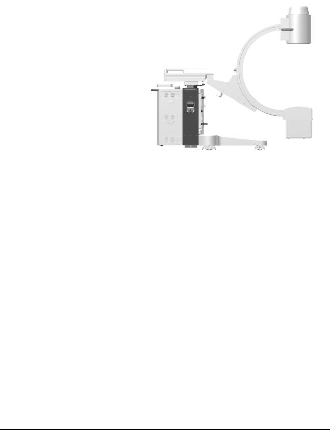
The unit ARCOVIS 3000 S/R is made up of two different parts: Mobile Stand and Display Station.
Mobile stand consisting of:
“C” Arm, Monobloc, Image Intensifier, Control Panel (Fig. 1).
Fig. 1
Pag. 8/76 - Rev. A |
[File:201175-G-01-01.doc] |
Villa Sistemi Medicali |
ARCOVIS 3000 S/R |
User's Manual |
Display Station consisting of:
•nr.1 orientable LCD monitor 17”, directly on mobile stand for digital systems with CCD 0,5K x 0,5K (Fig. 2). *
•“Low Profile Base Trolley” with
two LCD monitors 19” for video systems 0,5K2 (Fig. 3).
•“High Profile Base Trolley” with
two monitors 18” for video systems 1K2 (Fig. 4).
•“High Configuration” trolley with
two monitors 19”/18” for video systems 0,5K2 / 1k2 (Fig. 5).
Fig. 2
Fig. 3 |
Fig. 4 |
Fig. 5 |
* Note: the number of the monitors and the monitor trolley change according to the image system choice.
[File:201175-G-01-01.doc] |
Rev. A - Pag. 9/76 |
User's Manual |
ARCOVIS 3000 S/R |
Villa Sistemi Medicali |
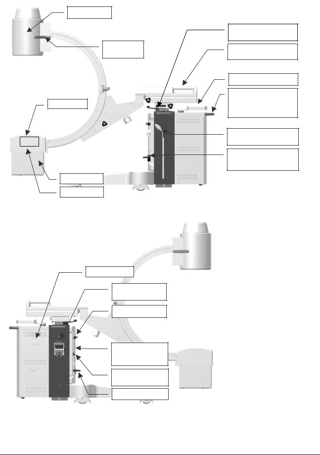
2.2. Mobile Stand
Image intensifier
Handles for the arm sliding
Collimator
Monobloc
Focus position
Fig. 6
Cable reel
Printer for dosimeter (optional)
ON key
Outlet for the fluoroscopy footswitch connector
Outlet for External
Interblocks (optional)
Mains cable
Fig. 7
Emergency push-button for the UP/DOWN movement
Handle for the horizontal arm group sliding
Control panel
Handles for the movement of the mobile image intensifier.
Handswitch for radiography / fluoroscopy control
Connector for the connecting cable between mobile image intensifier and monitor trolley
Pag. 10/76 - Rev. B |
[File:201175-G-01-01.doc] |

Villa Sistemi Medicali |
ARCOVIS 3000 S/R |
User's Manual |
2.2.1. Handles and brakes position for manual movements
The brake handle is take-up type. In order to avoid collision dangers with the unit or the user, always put the handle again in horizontal position.
1
3
4 2
Fig. 8
1
Fig. 9
1 |
5 |
2 |
4 |
|
3 |
1.Brake for the arm rotation around the horizontal axis.
Movement:±270°
2.Brake for horizontal sliding of the arm group. Movement: 220mm
3.Brake for the orbital arm rotation. Movement:123° (+90°÷-33°)
4.Brake for the overview movement of the arm group.
Movement: ±12,5°
1. Driving handle and rear wheels braking
Pos.1: brake ON
Pos.2: oblique movement
Pos.3: free movement
Pos. 4: oblique movement
Pos.5: right-left movement
[File:201175-G-01-01.doc] |
Rev. B - Pag. 11/76 |

User's Manual |
ARCOVIS 3000 S/R |
Villa Sistemi Medicali |
2.3. Keyboard
2.3.1.Unit
All keys are membrane type. The keyboard group can rotate ±45° in respect of the central position for its simpler use.
Fig. 10
Area 1
Vertical arm movement |
Laser targeting device |
|
OFF/ON |
||
|
||
System OFF |
Led for x-ray emission |
|
signal |
||
|
||
System ON |
Alarm signal |
|
|
|
Area 2
Digital image rotation 1
Image enlargement
Horizontal image reversal
Image edges enhancement
Motion Detector (unavailable function)
Stored images scrolling
Image transfer from the live monitor to the memory monitor
kV decrease / increase
Shutters diaphragm rotation
Shutters diaphragm closing/opening
Iris diaphragm closing/opening
ENTER + F1: “Utility Mode” selection
Commutation between LIVE image and MEM image on single monitor.
mA/mAs decrease / increase
1 For SBFM78, DIP and HRC memories series: by pressing at the same time the two rotation push-buttons for four seconds, there is the digital image rotation resetting.
Pag. 12/76 - Rev. F |
[File:201175-G-01-01.doc] |
Villa Sistemi Medicali |
ARCOVIS 3000 S/R |
User's Manual |
2.3.2. “Base Monitor Trolley”
Memories series SBFM /HRC
The memory series SBFM76 has not the keyboard.
The memories series SBFM78 have only the alphanumeric keyboard for the patient data input.
F1 |
allows PATIENT NAME (max 63 characters) to be inserted |
F10 |
allows DATE and TIME to be inserted |
F5 |
allows activation of NEGATIVE function on Memory Monitor |
HOME |
shows last image recently memorized |
END |
shows last image in the memory buffer |
PG UP |
scan of memorized images in increasing order |
PG DN |
scan of memorized images in decreasing order |
The SBFM device is equipped with the possibility of completely clearing all memorized images.
To use this function, press “PG UP” and “PG DN” commands at the same time for approximately 4 seconds (clearing time: from 10 sec to 2 min)
The keyboard can be placed under the unit keyboard (unit with monitor aboard) or on the highest shelf of the “Base Trolley” in “Low Profile” configuration.
The memories series HRC have the alphanumeric keyboard and mouse for the patient data input. Keyboard and mouse are placed on the highest shelf of the “Base Trolley” in “High Profile” configuration.
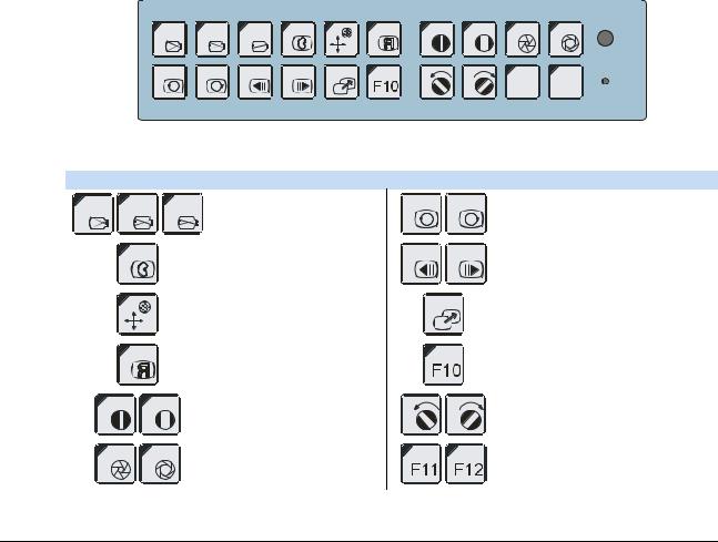
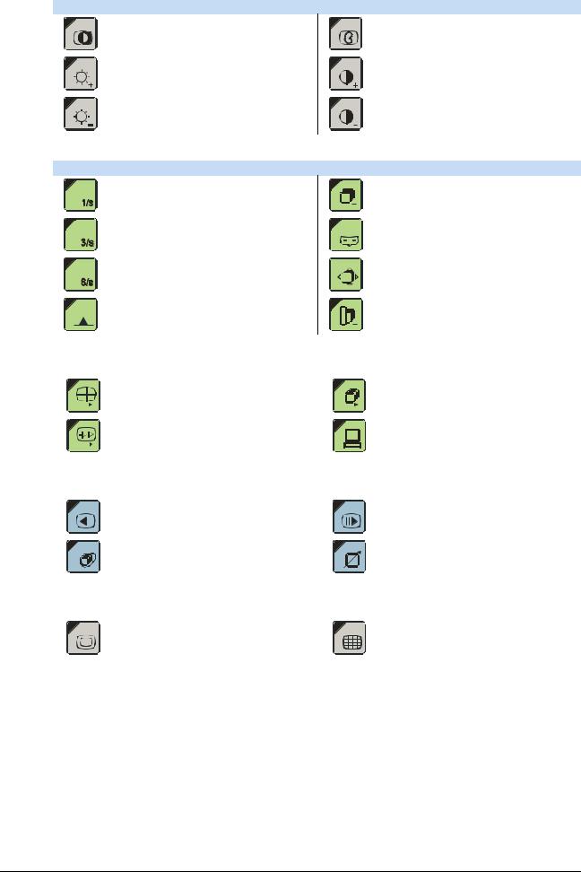
2.3.3.High Configuration trolley
On the High Configuration trolleys, there is always a small remote keyboard that duplicates some controls present on the unit keyboard.
All keys are membrane type.
Fig. 11
1^ line
Image enlargement
Image edges enhancement
Motion Detector (unavailable function)
Image reversal on vertical axis
Shutters diaphragm closing/opening
Iris diaphragm closing/opening
F11 F12 LINE
2^ line
Digital image rotation
Stored images scrolling
Image transfer from the live monitor to the memory monitor
n.u.
Shutters diaphragm rotation
n.u.
[File:201175-G-01-01.doc] |
Rev. F - Pag. 13/76 |

User's Manual |
ARCOVIS 3000 S/R |
Villa Sistemi Medicali |
Memories series DIP
The memories series DIP have a keyboard dedicated to the post processing. All keys are membrane type.
|
|
|
|
|
|
|
KEYBOARD |
|
|
|
|
|
|
|
|
|
Esc |
F1 |
|
F2 |
F3 |
|
F4 |
F5 |
F6 |
F7 |
F8 |
F9 |
F10 |
|
Del |
||
|
|
|
|
|
|
DOSE |
|
|
|
|
|
|
|
|
|
|
~ |
! |
@ |
# |
$ |
% |
^ |
|
& |
* |
|
( |
) |
_ |
+ |
||
` |
1 |
2 |
3 |
4 |
5 |
6 |
|
7 |
8 |
|
9 |
0 |
= |
= |
||
Q |
W |
|
E |
R |
T |
Y |
U |
|
I |
O |
P |
{ |
} |
|
|
|
|
|
|
|
|
|
|
|
|
|
|
|
|
[ |
] |
|
|
A |
S |
|
D |
F |
G |
H |
J |
|
K |
L |
: |
" |
|
|
|
|
|
|
|
|
|
|
|
|
|
|
|
|
; |
' |
|
|
|
Z |
X |
|
C |
V |
B |
N |
M |
|
< |
> |
|
? |
¦ |
Enter |
|
|
|
|
|
|
|
|
|||||||||||
Shift |
|
Ctrl |
|
|
|
Space |
|
, |
. |
|
Alt |
Shift |
|
|
||
|
|
|
|
|
|
|
|
|||||||||
|
|
|
|
|
|
|
|
|
|
|||||||
|
|
|
|
|
|
|
|
|
|
|||||||
ACQUISITION
M
L
ANGIOGRAPHY |
|
DICOM |
||
|
|
|
|
|
|
|
|
|
|
|
|
|
|
|
VIEW |
OVERVIEW |
ON
I.R.
Fig. 12
For an easier understanding they have been divided into 7 different groups: KEYBOARD, ACQUISITION, PROCESSING, ANGIOGRAPHY, DICOM, VIEW, OVERVIEW
|
|
KEYBOARD |
|
New exam |
Patients list |
DOSE |
Dose information |
VCR prearrangement |
|
|
|
|
Search start backwards |
Search start onwards |
|
Rotation + |
Rotation - |
ACQUISITION
SNAPSHOT control prearrangement
PULSED FLUOROSCOPY control prearrangement
Recursive filter selection
L
SMART filter activation / deactivation
L
Image reversal on vertical axis
Image rotation resetting
MEM image and FLUOROSCOPY alternation
Image storage key
Pag. 14/76 - Rev. C |
[File:201175-G-01-01.doc] |
Villa Sistemi Medicali |
ARCOVIS 3000 S/R |
User's Manual |
PROCESSING
It allows the images visualization in negative
Key to increase the brightness
Key to decrease the brightness
ANGIOGRAPHY
Angiographic acquisition rate selection 1 image per second
Angiographic acquisition rate selection 3 images per second
Angiographic acquisition rate selection 6 images per second
MAX OP control activation / deactivation
SHARP / SMOOTH / OFF edges processing
Key to increase the contrast
Key to decrease the contrast
Key for the mode activation of the subtraction between images
Mask acquisition key
SHIFTING PIXEL function activation
LAND MARK control activation
|
|
|
|
|
DICOM |
|
||||||
|
|
|
|
Single image sending to DTU |
|
|
|
|
|
|
Whole exam sending to DTU |
|
|
|
|
|
Current RUN sending to DTU |
|
|
|
|
|
|
DTU monitor commutation |
|
|
|
|
|
|
|
|
|
|||||
|
|
|
|
|
|
|
||||||
|
|
|
|
|
VIEW |
|
||||||
|
|
|
|
Memory number decrease |
|
|
|
|
|
|
Memory number increase |
|
|
|
|
|
|
|
|
|
|
|
|
||
|
|
|
|
ALTERNATE MEMORY procedure |
|
|
|
|
|
|
Key to delete the images stored in the |
|
|
|
|
|
control |
|
|
|
|
|
|
buffer (active only in DISKLESS mode) |
|
|
|
|
|
|
|
|
|
|||||
|
|
|
|
|
|
|
||||||
|
|
|
|
|
OVERVIEW |
|
||||||
|
|
|
|
Stored image zoom |
|
|
|
|
|
|
Stored images overview |
|
|
|
|
|
|
|
|
|
|
|
|
|
|
[File:201175-G-01-01.doc] |
Rev. A - Pag. 15/76 |

User's Manual |
ARCOVIS 3000 S/R |
Villa Sistemi Medicali |
Memories series HRP
The memories series HRP have the alphanumeric keyboard and the mouse for the patient data input.
All keys are membrane type.
Esc |
|
F1 |
F2 |
F3 |
F4 |
F5 |
|
F6 |
F7 |
` |
! |
@ |
# |
$ |
% |
< |
& |
|
* |
1 |
2 |
3 |
4 |
5 |
6 |
7 |
|
8 |
|
|
|
||||||||
|
|
Q |
W E |
R |
T |
|
Y |
U |
I |
Caps-lock |
|
A |
S |
D |
F |
G |
H |
|
J |
|
|
Z |
X |
C |
V |
B |
|
N |
M |
Ctrl |
|
|
Alt |
|
|
|
|
|
|
|
F8 |
F9 |
F10 |
F11 |
F12 |
|
|
|
|
|
( |
) |
+ |
_ |
|
Num |
Scroll |
|
|
|
9 |
0 |
|
|
|||||
|
|
|
Pause |
||||||
|
= |
- |
|
Lock |
Lock |
Screen |
|||
|
O |
P |
{ |
} |
| |
7 |
8 |
9 |
* |
|
[ |
] |
\ |
Home |
|
Pag |
|||
K |
L |
: |
" |
|
E n t e r |
4 |
5 |
6 |
- |
; |
|
|
|
|
|||||
' |
|
|
|
|
|||||
|
|
> |
? |
|
|
1 |
2 |
3 |
+ |
|
, |
. |
/ |
|
|
End |
|
Pag |
|
|
|
|
|
|
|
0 |
. |
E n t e r |
|
|
|
Alt Gr |
|
Ctrl |
|
Ins |
Del |
||
Pag. 16/76 - Rev. A |
[File:201175-G-01-01.doc] |
Villa Sistemi Medicali |
ARCOVIS 3000 S/R |
User's Manual |
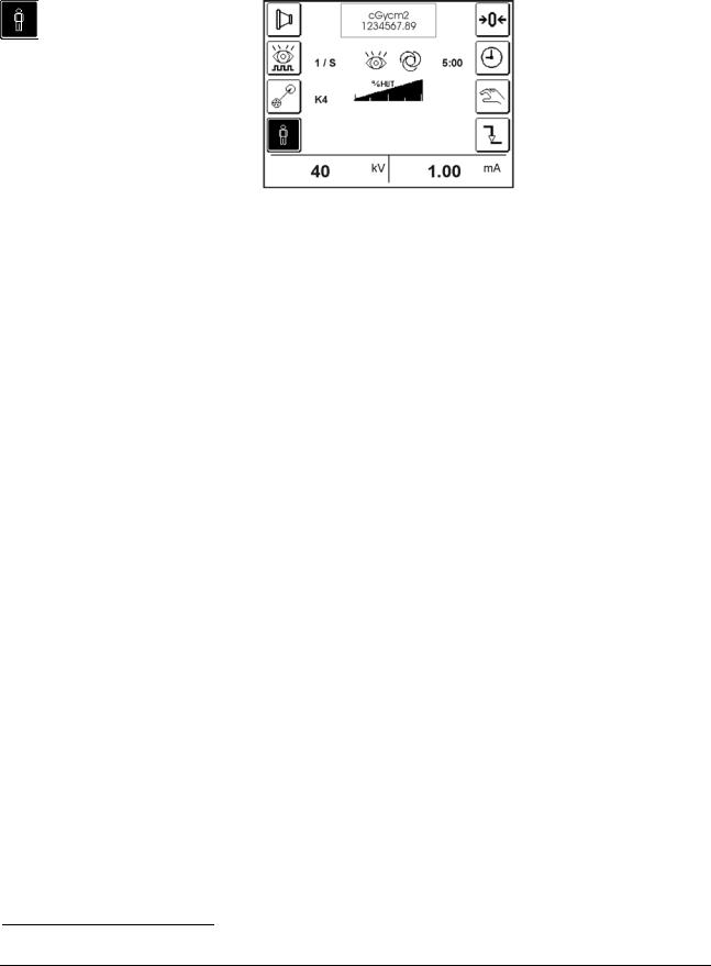
2.3.4. Display
Alphanumeric touch-screen display 5” for x-ray parameters and warning/error messages.
The keys, so-called at “retention”, are displayed:
in positive on white background for the non-active function
in negative on black background for the active function
Note: the box with the dose indication is displayed only if the dosimeter is installed and in working condition.
2.3.5. Audible signals |
|
1 BEEP2 |
Sound signal when any key is pressed. |
2 BEEPS |
Storage OK. |
A LONG BEEP |
Alarm, malfunction. |
(about 1sec) |
|
2 It is possible to deactivate the audible signals or modify the volume (§3.6.10 Utility Mode).
[File:201175-G-01-01.doc] |
Rev. A - Pag. 17/76 |
User's Manual |
ARCOVIS 3000 S/R |
Villa Sistemi Medicali |
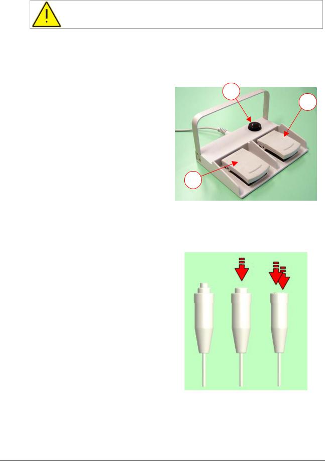
2.4. Fluoroscopy control footswitch
The footswitch is enabled only in fluoroscopy mode.
The fluoroscopy control footswitch consists of a double-step pedal and two single-step ones. The functions in the different modes are:
1.Left pedal (two steps):
Fluoroscopy Mode:
1° step: fluoroscopy control. |
3 |
|
2° step: image storage; in continuous |
||
2 |
||
fluoroscopy the current image is stored. |
2. |
Right pedal (a step): |
|
|
|
Pulsed fluoroscopy mode. |
|
|
3. |
Third pedal (a step): |
|
|
|
Fluoroscopy mode: |
1 |
|
|
"snapshot" |
control |
(high-contrast |
exposure with reduced background noise).
Fig. 13
2.5. Handswitch for radiography / fluoroscopy control
The control handswitch is made of a twosteps switch.
Radiography mode:
1° step: preparation control. 2° step: emission control.
In radiography mode it is possible to press immediately the exposure control (2° step), with an emission delay due to the anode
starting phase (only for rotating anode version).
It is possible to control Fluoroscopy and Storage even with the radiography handswitch.
Fluoroscopy mode:
1° step: fluoroscopy control. 2° step: image storage.
Normally the function is enabled. In order |
Fig. 14 |
to disable it, it is necessary Service |
|
intervention. |
|
Pag. 18/76 - Rev. C |
[File:201175-G-01-01.doc] |
Villa Sistemi Medicali |
ARCOVIS 3000 S/R |
User's Manual |
|
||
2.6. Monitor Trolley |
|
|
|
|
|
|
|
|
|
||
|
Unit “ARCOVIS 3000 S/R” with monitor aboard |
Unit “ARCOVIS 3000 S/R” + “Low Profile Base Trolley” |
|
||
|
|
|
|
|
|
|
Unit “ARCOVIS 3000 S/R” + “High Profile Base Trolley” |
Unit |
“ARCOVIS 3000 S/R” + “High Configuration” |
|
|
|
|
|
|
trolley |
|
|
|
|
|
|
|
[File:201175-G-01-01.doc] |
Rev. A - Pag. 19/76 |
User's Manual |
ARCOVIS 3000 S/R |
Villa Sistemi Medicali |
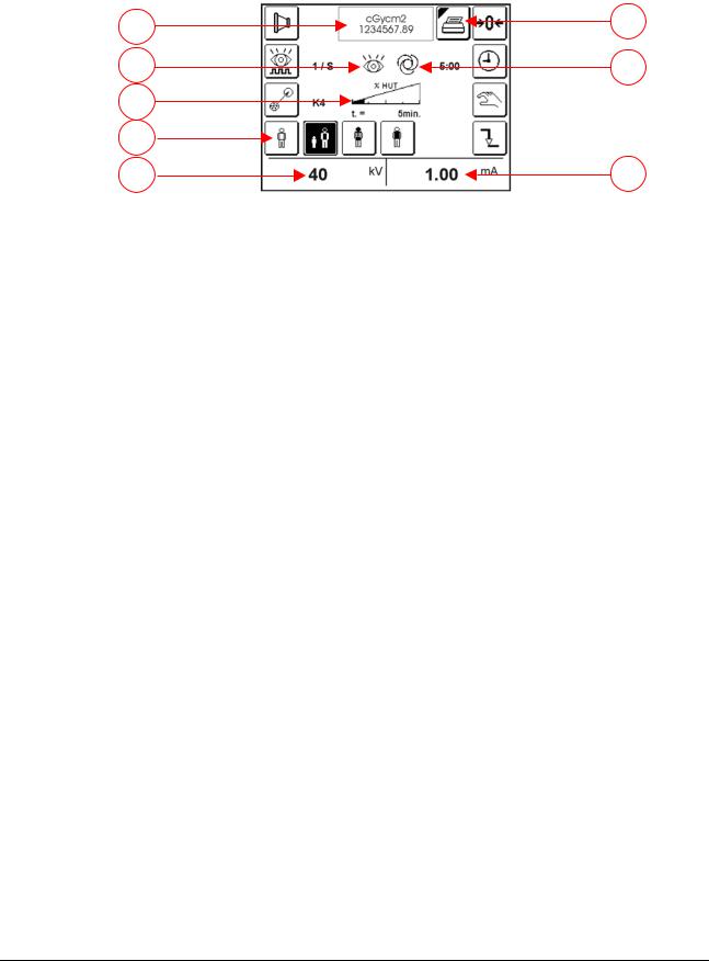
2.7. Operative messages
Display in fluoroscopy mode
1 |
8 |
|
|
2 |
7 |
3
4
5 |
6 |
1Indication of the dose value (only if the dosimeter is present and in working condition / MESSAGES and/or ERRORS Area)
2Indication of the FLUOROSCOPY / RADIOGRAPHY phase.
3Indication of the available thermal units (HUT), expressed in percentage from 0% (indicator completely white and spent HUT) to 100% (indicator completely black and available HUT).
When the residual HUT value allows a use of the unit below five minutes, under the indicator will appear also the residual time indication (t = …min), valued in function of the employed power. Simultaneously it’s issued an acoustic alarm not modifiable.
When the residual HUT reach 0%, the x-rays emission block intervenes.
It’s possible to exceed this limit and proceed with the x-rays emission (only in fluoroscopy mode) till intervention of monobloc thermal security.
This choice must be performed by Service personnel and on express request of the final user.
As the monobloc temperature decreases, the HUT will be regenerated. Residual time indication will disappear, when thermal units allow a use exceeding five minutes.
4Selection of the Anatomic Curve in Fluoroscopy (Standard / Paediatric / Pelvis-Head /
Standard for sturdy patient (only for rotating anode with camera 1K2)).
5Indication of the set kV value. It changes in Automatic mode or in Manual mode by using the kV+ and kVkeys of the control panel.
6Indication of mA value concerning kV and the selected curve. During the exposure it indicates the measured mA value.
7Indication of the AUTOMATIC / MANUAL mode.
8Dose printing key. It appears if the dosimeter is present and in working condition and if the printing mode in Utility Mode is selected (§3.6.10).
Pag. 20/76 - Rev. C |
[File:201175-G-01-01.doc] |
Villa Sistemi Medicali |
ARCOVIS 3000 S/R |
User's Manual |
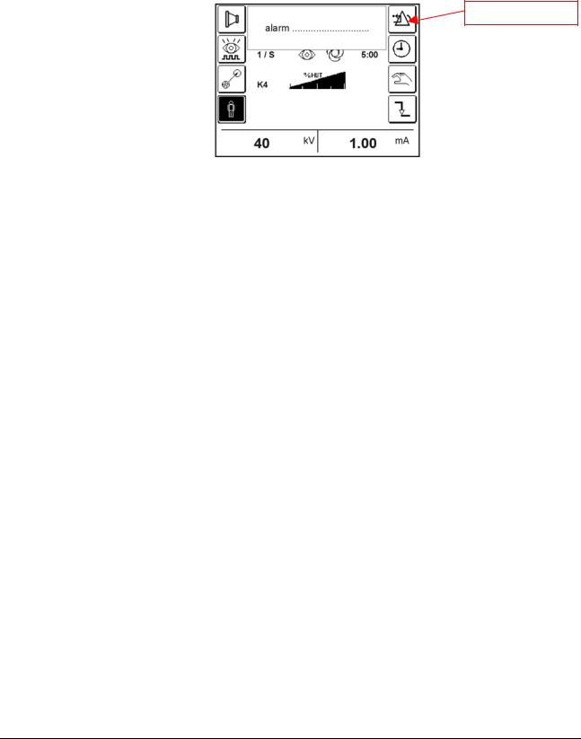
2.8. Alarm messages
In case of alarm condition, the alarm messages are displayed in an appropriate box with audio-visible signals.
The key for the dose visualization resetting changes in ALARM RESET.
When an error/warning appears, press the key “ALARM RESET” to reset the audible signal, delete the message and go on to work.
ALARM RESET
The table indicates how to proceed in case of faults and anomalies.
|
Text |
|
|
|
Meaning |
|
|
|
|
Intervention |
|
|
|||
|
|
|
|
|
|
|
|
|
|||||||
|
|
|
|
The dosimeter does not reply. |
|
|
|
Press the “ALARM RESET” key in |
|||||||
|
|
|
|
|
|
|
|
|
|
|
order to go on to work. |
|
|
||
|
DOSIMETER NOT OK |
|
|
|
|
|
|
|
|
|
Check that it is not selected when |
||||
|
|
|
|
|
|
|
|
|
|
it is not present on the unit. |
|
||||
|
|
|
|
|
|
|
|
|
|
|
|
||||
|
|
|
|
|
|
|
|
|
|
|
Call Service to perform the |
||||
|
|
|
|
|
|
|
|
|
|
|
necessary checks. |
|
|
||
|
|
|
|
At least eleven months are passed |
|
|
Press the “ALARM RESET” key in |
||||||||
|
MAINTENANCE REQUIRED |
|
|
from |
the last performed |
planned |
|
|
order to go on to work. |
|
|
||||
|
|
|
maintenance. |
|
|
|
|
|
Call Service to perform the |
||||||
|
|
|
|
|
|
|
|
|
|||||||
|
|
|
|
|
|
|
|
|
|
|
planned maintenance. |
|
|
||
|
|
|
|
|
|
|
|
|
|
|
Press the “ALARM RESET” key in |
||||
|
|
|
|
|
|
|
|
|
|
|
order to go on to work. |
|
|
||
|
|
|
|
|
|
|
|
|
|
|
Warning! |
This |
function |
results |
|
|
REAL TIME CLOCK ERROR |
|
|
The system clock does not work. |
|
|
particularly |
important |
for |
the |
|||||
|
|
|
|
|
calculation of the thermal units |
||||||||||
|
|
|
|
|
|
|
|
|
|
|
|||||
|
|
|
|
|
|
|
|
|
|
|
recovery. |
|
|
|
|
|
|
|
|
|
|
|
|
|
|
|
Call Service to perform the |
||||
|
|
|
|
|
|
|
|
|
|
|
necessary checks. |
|
|
||
|
EXHAUSTED THERMAL UNIT |
|
|
The |
thermal capacity |
of |
the |
|
|
Wait for |
the |
thermal |
units |
||
|
|
|
monobloc is exhausted. |
|
|
|
|
recovery. |
|
|
|
|
|||
|
|
|
|
|
|
|
|
|
|
|
|
||||
|
EXHAUSTED XR TIME |
|
|
Continuous fluoroscopy |
|
time |
|
|
Release the footswitch and go on |
||||||
|
|
|
exhausted (max 10min) |
|
|
|
|
with the operation. |
|
|
|||||
|
|
|
|
|
|
|
|
|
|
||||||
|
|
|
|
The |
generator |
does |
not |
|
|
Switch the unit OFF, wait for some |
|||||
|
GENERATOR OFFLINE |
|
|
|
|
seconds and switch ON again. |
|||||||||
|
|
|
communicate with the central unit. |
|
|
In case the error persists, call |
|||||||||
|
|
|
|
|
|
||||||||||
|
|
|
|
|
|
|
|
|
|
|
Service. |
|
|
|
|
|
|
|
|
|
|
|
|
|
|
|
Switch the unit OFF, wait for some |
||||
|
CAN-BUS ERROR |
|
|
Error in the field bus |
|
|
|
|
|
seconds and switch ON again. |
|||||
|
|
|
|
|
|
|
|
In case the error persists, call |
|||||||
|
|
|
|
|
|
|
|
|
|
|
|||||
|
|
|
|
|
|
|
|
|
|
|
Service. |
|
|
|
|
|
MEMORY CONTROLLER |
|
|
The |
memory |
does |
|
not |
|
|
Switch the unit OFF, wait for some |
||||
|
|
|
|
|
|
seconds and switch ON again. |
|||||||||
|
OFFLINE |
|
|
communicate with the central unit. |
|
|
In case the error persists, call |
||||||||
|
|
|
|
|
|
|
|
|
|
|
Service. |
|
|
|
|
[File:201175-G-01-01.doc] |
Rev. B - Pag. 21/76 |

User's Manual |
ARCOVIS 3000 S/R |
Villa Sistemi Medicali |
MOTOR DRIVER
COMMUNICATION * The collimator motor does not communicate with the central unit.
* Iris – Rotation – Shutters
FILAMENT ERROR |
Problems |
found |
in |
the |
filament |
|
management. |
|
|
|
|||
|
|
|
|
|||
|
|
|
||||
KV ERROR |
Error in the kV generation |
|
||||
|
|
|
|
|||
mA OVERLOAD |
Error in the mA |
reading |
(over the |
|||
max. allowed limit) |
|
|
|
|||
|
|
|
|
|||
|
|
|||||
THERMIC ALARM |
The temperature of the monobloc has |
|||||
|
reached the max. allowed value. |
|||||
|
|
|||||
EMERGENCY UP/DOWN |
Pressed UP/DOWN emergency push- |
|||||
PUSHED |
button. |
|
|
|
|
|
|
|
|
|
|
|
|
POWER SUPPLY ERROR |
Incorrect secondary power supply |
|||||
|
||||||
|
|
|
|
|||
FOOTSWITCH OR |
Faulty or |
damaged |
footswitch or |
|||
handswitch for the x-ray control |
||||||
HANDSWITCH ERROR |
||||||
|
|
|
|
|
||
|
|
|||||
STARTER FAULT |
Error in the circuit of the rotating |
|||||
Only rotating anode |
anode. |
|
|
|
|
|
|
|
|
|
|
||
|
For the units provided with the door |
|||||
OPEN DOOR WARNING |
control, the door to enter the room is |
|||||
|
open. |
|
|
|
|
|
VIDEO SIGNAL NOT OK |
The video signal is not present or it is |
|||||
not bright enough. |
|
|
|
|||
|
|
|
|
|||
|
|
|
|
|
|
|
UNAVAILABLE INVERTER |
Unavailable inverter power supply |
|||||
POWER SUPPLY |
||||||
|
|
|
|
|
||
|
|
|||||
MAX. X-RAY TIME |
The max. exposure time has been |
|||||
|
reached. |
|
|
|
|
|
|
|
|||||
TIMEOUT |
The preparation handswitch is held |
|||||
down for more than 15 seconds |
||||||
|
without performing x-rays. |
|
||||
MANUAL X-RAY STOP |
The x-ray hand switch has been |
|||||
|
released before the end of the |
|||||
|
exposure. |
|
|
|
|
|
MISSING PULSES |
Control pulses lack from the memory |
|||||
|
|
|
||||
CCA BUSY |
Busy central unit control |
|
||||
Press the “ALARM RESET” key in order to go on to work (it is possible to go on with XR, if the I.I. field results to be free).
In case the error persists, call Service. Press the “ALARM RESET” key in order to go on to work.
If the error repeats and persists also at the next start-up, call Service.
Press the “ALARM RESET” key in order to go on to work.
If the error repeats and persists also at the next start-up, call Service.
Press the “ALARM RESET” key in order to go on to work.
If the error repeats and persists also at the next start-up, call Service.
Wait for the tube cooling
Reset the correct working of the emergency push-button by turning it clockwise.
Switch the unit OFF, wait for some seconds and switch ON again.
In case the error persists, call Service. Disconnect and reconnect the footswitch.
In case the error persists, call Service. Switch the unit OFF, wait for some seconds and switch ON again.
In case the error persists, call Service. Check that the door is closed correctly.
In case the error persists, call Service. Switch the unit OFF, wait for some seconds and switch ON again.
Check that the trolley is connected to the unit and that the BNC cables are properly connected to the monitors.
In case the error persists, call Service. Switch the unit OFF, wait for some seconds and switch ON again.
In case the error persists, call Service. Press “ALARM RESET” key to go on, repeat x-rays.
In case the error persists, call Service. Release the preparation handswitch and repeat the operation.
Press “ALARM RESET” key to go on and repeat the exposure.
Press the “ALARM RESET” key in order to go on to work.
In case the error persists, call Service. Press the “ALARM RESET” key in order to go on to work.
In case the error persists, call Service.
Pag. 22/76 - Rev. A |
[File:201175-G-01-01.doc] |
Loading...