

Villa Nical Service manual

Analog CCD Camera N23 - 8
ANALOG CCD TV CAMERA - 8
[File: TV-CAM-ANA_E00R02.doc]
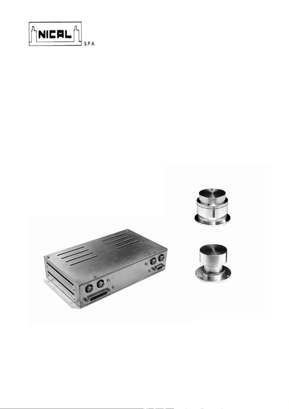
CCD CAMERA
N23
TV CAMERA FOR USE WITH
X-RAY IMAGE INTENSIFIER
October 2004 Release 1
Service Manual

SUMMARY
1. INTRODUCTION 2
2. SAFETY INSTRUCTIONS 2
2.1. Warnings 2
2.2. Environmental risks and disposal 2
2.3. Symbols 2
3. DESCRIPTION 3
3.1. Identification labels 3
3.2. Description 3
4. TECHNICAL DATA & CERTIFICATIONS 4
5. MAINTENANCE AND CLEANING 5
5.1. Maintenance 5
5.2. Cleaning 5
6. CCD CAMERA N23 DESCRIPTION 5
7. COMPONENT POSITIONS 6
7.1. POSITIONING OF CAMERA HEAD 6
7.2. POSITIONING OF CCU 6
8. STANDARD INSTALLATION 7
8.1. Camera Head (CCD head adjustments) 7
8.2. CCU adjustment 7
8.3. Set up points 8
8.4. Customer Set up 9
8.5. Factory set up only 10
9. CCD CAMERA CONNECTORS 11
9.1. CCD camera head connector 11
9.2. Command 12
9.3. Block diagram CCU rack N23 14
10. FUNCTION AND MEMORY CONTROL 15
10.1. Memory function of CCD camera 15
10.2. Recording to and playback from memory modes. 15
10.3. Direct access memory (ADD5=1) 16
10.4. Manual selection mode (ADD5=0, ADD1=1, ADD0=0) 16
10.5. Multiple cine-loop mode without position reset (ADD5=0, ADD1=0, ADD0=1) 17
10.6. Multiple cine-loop mode with position reset (ADD5=0, ADD1=0, ADD0=0) 18
10.7. Erasing memory mode (ADD5=0, ADD1=1, ADD0=0) 18
11. ELECTRICAL DIAGRAMS 18
11.1. General circuit diagram and block diagram of N23 CCD system. 18
NICAL Spa CCD CAMERA N23 Service Manual Release 1 Page 1/20

1. INTRODUCTION
The CCD camera N23 system acquires and digitizes radiological images.
This equipment must be used in accordance with the manual and is not intended for any use outside of that herein described.
The N23 is a device component and interfaces to x-ray equipment and as such must be used by qualified personnel only with
knowledge of all x-ray protection.
The user is also responsible for all additional compliance certification and correct function at time of installation.
2. SAFETY INSTRUCTIONS
NICAL S.p.A. accepts no responsibility for any misuse of the CCD camera N23 outside of its original design and description as set
forth in manual.
Furthermore NICAL S.p.A accepts no responsibility for any damages to camera, operator, and patient, due to incorrect installation or
unauthorized modification (mechanical or electrical) and misuse of N23 CCD system.
Only personnel authorized by NICAL S.p.A may service equipment.
Authorized persons may only remove covers when servicing electrical power concerns.
It is mandatory to replace parts with only original NICAL S.p.A. replacement components.
2.1. Warnings
1. Read these instructions carefully. Save these instructions for future reference.
2. Follow all warnings and instructions marked on the product.
3. Slots and openings in the cabinet are provided for ventilation; to ensure reliable operation of the product and to protect it
from overheating, these openings must not be blocked or covered.
4. This product should be operated from the type of power indicated on the marking label. If you are not sure of the type of
power available, consult NICAL Company.
5. When the CCD camera is turned on make a white test in according to verify the quality image.
2.2. Environmental risks and disposal
The CCD CAMERA N23 contains some materials that can be recycled at the end of its life cycle.
In particular the system contains the following materials:
Iron, copper, lead, aluminium, non-biodegradable plastics, and fiber of glass printed circuit boards.
NICAL S.p.A. does not accept equipment for recycling.
2.3. Symbols
Symbol Description
DC
Attention, consult the documentation
Direct current
Compliance to Medical Device directive:93/42
Device with type B parts
Protective earth (ground)
NICAL Spa CCD CAMERA N23 Service Manual Release 1 Page 2/20
N
R
3. DESCRIPTION
N
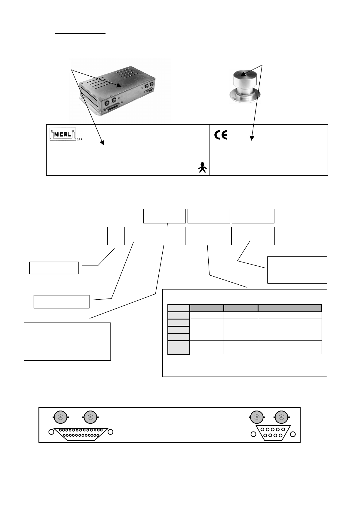
3.1. Identification labels
1
Made in Italy
Code: N23XXXXXX Type: N23 CCD
Line: 24V DC 20W
Serial Number: xxxxx Date: 04/03
ICAL Spa Via Soffredini, 43 20126 Milano – Italy Serial Number: xxxxx
3.2. Description
50 CCIR 625/50
N Normal
Rotation
A Main analog board only
I Digital + H/V Inversion +
recursive filter
H Digital + H/V Inversion +
DRF(Dynamic recursive filter).
N23 I 0
MANUFACTURER: NICAL SPA
MAIN DIGITAL
50
1
2
N23 CCD CAMERA HEAD
0123
BOARD
PROCESSING
BOARD
Video 1 Video 2 Video 3 - Video 4
N
0
1
2
3
525 / 625 --- --525 / 625 525 / 625 --525 / 625 525 / 625 525 / 625
525 / 625 525 / 625 1049 / 1249
625 50Hz
525 60Hz
MEMORY
BOARD
625 50Hz
525 60Hz
A 0 Frames
1 32 Frames
2 256 Frames
4 512 Frames
625 100Hz
525 120Hz
Video 1 from main analogic board
Video 2 / 3 / 4: LIH & recursive filter & memory if present
VIDEO 4
VIDEO 3
CABLE
CONTROL + PWR CABLE
(Female DB25)
VIDEO 1
CAMERA HEAD CABLE
VIDEO 2
CABLE
(female DB9)
NICAL Spa CCD CAMERA N23 Service Manual Release 1 Page 3/20

4. TECHNICAL DATA & CERTIFICATIONS
Available CCD scanning system
Scanning aspect ratio:
:
CCD Camera Head :
CCD Type:
Integrated optical lens system:
Image intensifier output screen:
Mounting frames:
CCD / CCU Characteristics :
Resolution:
Gamma correction:
Video output A/D converter:
Video Bandwidth:
DRF (Dynamic Recursive Filter):
MD (Motion Detection):
Standard Recursive filter:
Memory:
Automatic video level compensation:
Automatic x-ray kV/mA compensation:
Dynamic contrast compensation for better image uniformity:
Very high dynamic video amplifier:
High precision electronic circle:
Video output signal:
Video output standards :
Analog Main board (Video 1):
Digital Main board (Video 2 )
recursive filter and/or DRF & LIH & frame stored:
Digital processing board (Video 3)
(Video 4):
Operating conditions :
Working temperature range:
Store temperature range:
Humidity:
Mechanical specifications :
Control unit: dimension (WxDxH)/ Weight :
Camera head: dimension (φ x H)/Weight :
Available power supply :
Approvals :
Safety:
EMC:
Others:
Options :
CCIR 625/50 interlaced (752 x 582 pixels)
EIA 525/60 interlaced (768 x 494 pixels)
4:3
½” Interline low blooming CCD sensor (470.000 pixels)
High resolution with adjustable focus and diaphragms
From 15 to 40mm diameter.
From 6” inch to 16” inch I.I.
20 lines-pairs (on 6” image intensifiers)
0.4 or 1
10 bits
20 MHz ± 3dB
Yes (N23H)
Yes (N23)
Factor 2,4,8,16
16 bits
Yes
Yes. Analog and digital (up/down)
Yes (shading)
Yes
Yes
1 Vpp (0.3 Vpp Sync)
1 BNC 75Ω - ( CCIR 625/50 or EIA 525/60 )
1 BNC 75Ω - ( CCIR 625/50 or EIA 525/60 )
2 BNC 75Ω
CCIR 625/50 interlaced
EIA 525/60 interlaced
CCIR 1249/50 interlaced
EIA 1049/60 interlaced
CCIR 625/100Hz interlaced
EIA 525/120Hz interlaced
-10°C to +45°C
-40°C to +55°C
Operating to 95% relative humidity (non-condensing)
226 x 120 x 46mm 0,550 Kg
(Standard) 85x87mm 0,460 Kg
(with Rotation) 101x87mm 1,1 Kg
24Vdc ± 20%
EN 60601-1
EN 60601-1-2
CE-label according 93/42 CEE directive for medical devices.
360° Continuous rotating camera head (with slip ring)
C-Mount
Zoom lens
Neutral density filter: 25% or 50% light transmission
NICAL Spa CCD CAMERA N23 Service Manual Release 1 Page 4/20

5. MAINTENANCE AND CLEANING
5.1. Maintenance
The system will serve you well if you take care of it.
Do not spill liquids on the system.
Do not subject the system to heavy shock and vibration.
Never place objects on top of the system to avoid damaging it.
All electrical equipment should be used according to the instruction provided. It is advised to control all connections and the
image quality on a regular basis. It will guarantee an efficient function and long product life.
Maintenance guide
Frequency Description
2 years Cable connection and condition inspection
1 year Image quality check
5.2. Cleaning
When cleaning the system, follow these steps:
Power off the system.
Use a soft cloth moistened with water.
Do not use liquid or solvents.
6. CCD CAMERA N23 DESCRIPTION
The N23 CCD camera, manufactured using printed circuit board with SMD technology, offers better performance than NICAL’ s
well know N20 camera system. It uses the same camera head of CCD camera N20 and the same wiring and controls. All previously
offered configurations are available in the new system along with vertical-horizontal inversion and continuous 360° rotation. Digital
integrated image processing has been changed from 9 to 10 bit output resolution for better performance. This new system allows
obtaining 512 frames memory with icons and numbered frames displayed. These new characteristics put the new N23 CCD at the top
of the standard resolution CCD cameras for x-ray image intensifier and radiological applications.
A very important new feature available on N23H is DRF (Dynamic Recursive
Filter) which allows changing pixel by pixel the recursive filter factor. This type
of filter offers better photonic noise reduction, eliminating also image
persistence during patient moving.
NICAL Spa CCD CAMERA N23 Service Manual Release 1 Page 5/20
7. COMPONENT POSITIONS
18,7
18,7
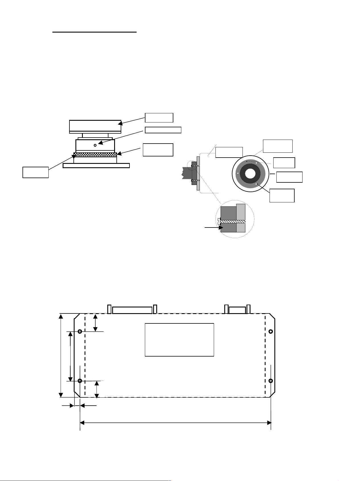
7.1. POSITIONING OF CAMERA HEAD
Place camera head into output phosphor well of image intensifier (see figure below).
Line up holes at 120’ and fasten with screws to intensifier. If necessary it is possible rotate camera head 90° by 90° with screws at
the bottom of the cover head.
NOTE: For best performance it’s better to insulate the camera head from the ground system. For this reason the camera head has
a special superficial treatment to insulate the head when it is fixed with screws to the system. Be sure to use plastic insulation with
screw to fix head at the system.
CCD
ADAPTER
ALUMINIUM
COVER
ALLEN SCREW
ADJUSTABLE
DISTANCE
RING
CCD ADAPTER
IMAGE
INTENSIFIER
METAL BODY
IMAGE
INTENSIFIER
CCD
ADAPTER
IMAGE
INTENSIFIER
SET
SCREW
7.2. POSITIONING OF CCU
Line up holes at the bottom of the cover CCU and fasten with screws to the system.
NICAL COMPANY DOES NOT PROVIDE THE SET SCREWS
120 mm
82 mm
5 mm
RACK CCD N23
BOTTOM
VIEW
217 mm
NICAL Spa CCD CAMERA N23 Service Manual Release 1 Page 6/20
ADJUSTABLE
DISTANCE
8. STANDARD INSTALLATION
All the CCD cameras are calibrated in Nical Company and the customer may regulate the following functions only:
1. DISTANCE (IMAGE DIMENSION)
2. FOCUS OF THE CCD CAMERA HEAD
3. IRIS OF THE CCD CAMERA HEAD
4. SHADING REGULATION
The parts where it is possible to find these regulations are:
1-2-3 CCD CAMERA HEAD
4 N23_ANB1 BOARD
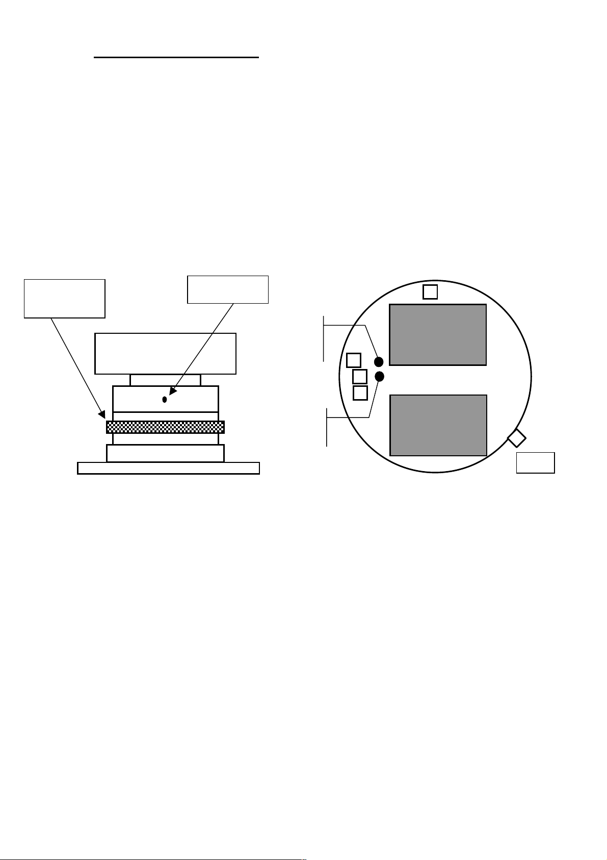
8.1. Camera Head (CCD head adjustments)
RING
DISTANCE (IMAGE DIMENSION) SET TO REQUIRED PICTURE DIMENSION.
FOCUS SET FOR BEST FOCUS BETWEEN IMAGE INTENSIFIER AND
DIAPHRAGM WITH STANDARD DOSE REQUESTED, SET SCREW OF IRIS UNTIL
ALLEN
SCREW
FOCUS
IRIS
UNLOCK THE ALLEN SCREW, ADJUSTABLE DISTANCE RING AND
ROTATE THE INTERNAL CYLINDER UNTIL THE REQUESTED
DISTANCE.
CAMERA HEAD
THE 2 LEDS ON N23_ANB1 TURN OFF. (In these conditions the value of
video signal is equal to 1,3V at test point (TP1)
XCD01
1
CD2-BOARD
2
3
4
DRV 61-BOARD
TP1
8.2. CCU adjustment
SHADING MOVE JUMPER J4 (SHADING) ON N23_ANB1 BOARD FROM
POSITION 1-2 (OFF) TO POSITION 2-3 (ON), AND ADJUST P7, P8, P9,
P10 FOR BEST IMAGE UNIFORMITY (using flat x-ray image at standard
dose).
NICAL Spa CCD CAMERA N23 Service Manual Release 1 Page 7/20

8.3. Set up points
R94
R157
R156
1
2
3
R163
SW2
P3
P2
P1
J6
1 2 3
SW4
1 2 3
1
SW3
2
3
J2
1 2 3 4
J4
1 2 3
P11
P7P10P9P8P6P5
CODE NAME DESCRIPTION
SW2 AUTO BLK
R157 BLACK LEVEL
R156
BLACK LEVEL
AUTO CONTROL
SW3 AUTO WTH
R163
AUTO
WHITE LEVEL
R94 GAMMA
ANALOG VIDEO (2-3)
SW4
/SYNC PULSE PER
SCOPIA PULSATA (1-2)
J6
J4
P7-P8-P9-P10
J2
GAMMA
CORRECTION
SHADING
ENABLE
SHADING
(VS-VP-HS-HP)
VIDEO & AUTO
CIRCLE ENABLE
P6 VIDEO CIRCLE
P5 AUTO CIRCLE
P3 CIRCLE SIMMETRY
P1 VERT SHIFT
P2 HOR SHIFT
P4 AUTO KV LEVEL
P11 AUTO KV WINDOW
ROTATION RESET
J5
(CCD CAMERA WITH
ROTATION ONLY)
Ad just black level pedestal (BOTTOM BLACK). When Auto BLK off (SW2
OFF: position 2-3) regulate the pedestal to 30mV respect referring level
Ad just black level pedestal (BOTTOM BLACK). When Auto BLK on (SW2 ON:
position 1-2) regulate the pedestal to 30 mV respect referring level.
Ad just white level (TOP WHITE). Set to 590mV video analog signal respect
referring level. Use jumper SW3=ON (position 1-2) to select or reject this feature.
It is used to enable on Video 1 an analogic signal: (position 2-3) or an output at
25Hz/30Hz square wave (position 1-2) used as sync pulse in high contrast
Set the shading gain to compensate picture not uniformity because of Image
Intensifier. Use jumper J4=ON (position 2-3) to select or reject this feature
J2 position 3-4: VIDEO CIRCLE; J2 position 2-3 AUTO CIRCLE
Adjust circle blanking diameter. Use jumper J2=ON (position 3-4) to select or
Adjust measurement circle area used by automatic gain and x-ray KV control.
Adjust the symmetry of video circle. Use jumper J2=ON (position 3-4) to select or
Adjust the vertical centering of video circle. Use jumper J2=ON (position 3-4) to
Adjust the horizontal centering of video circle. Use jumper J2=ON (position 3-4)
Increase or decrease the sensibility of the automatic KV control. This feature is
very useful in according to adapt the CCD camera N23 for any kind of X-ray
Position 1-2: Manual reset. To bring camera head to 0 position ground pins CW
(pin 17) and CCW (pin 4) on interface connector DB25 at the same time.
It is used to enable the Black Level Auto Control.
(SW2 ON: position 1-2)
It is used to enable the Auto White Level.
(SW3 ON: position 1-2)
Factory adjusted
Jumper J6 position 1-2: gamma value is 0, 4.
Jumper J6 position 2-3: gamma value is 1
It is used to enable shading regulations
It is used to enable the video and auto video regulations
reject this feature
Use jumper J2=ON (position 2-3) to select or reject this feature
reject this feature
select or reject this feature
to select or reject this feature
Set the value of AUTO KV
generator
Position 2-3: Automatic reset when system turned -on.
Location: N23- MB0.
1
2
3
P4
N23_ANB1
J5
NICAL Spa CCD CAMERA N23 Service Manual Release 1 Page 8/20
 Loading...