

Villa Endos AC-ACP Service Manual
ENDOS AC / ACP 0051
Release 13 July 2007 (Rev. 6)
Service Manual
Service Manual
Service ManualService Manual
SERVICE MANUAL
Revision history
Revision history
Revision history
Revision historyRevision history
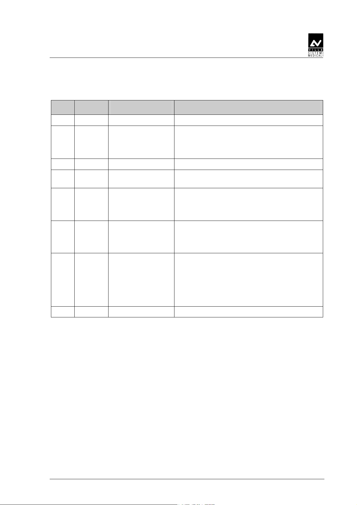
Rev. Date Page/s Modification description
0 07.02.03 - Document approval.
1 11.04.03 All Introduction of KAILONG (China) X-ray tube.
Introduction of remote X-ray button with light
signaling of "Ready" or "Exposure in progress".
(Ref. RDM 5599)
2 25.09.03 All Remote Timer version release
3 26.03.04 8 Notify body change for CE mark.
(Ref. RDM 5781)
4 15.03.05 8, 20, 78, 79 Editorial correction on Enabling/Disabling the
"Ready" key.
Modified the DP arm label.
(Ref. RDM 5938, RDM 6052)
5 10.01.05 30, 91 Dose linearity reference measurement time
updated.
Added electrical safety NOTE.
(Ref. RDM 6164)
6 13.07.07 5, 6, 8,
33, 34, 40, 41,
51, 110, 116,
118
Improvement of ceiling plate installation
procedure.
Added NOTE with indication that the device is
supplied as unit to be installed permanently
(EN60601-1 – paragraph 19).
Spare Parts chapter update.
(Ref. RDM 6568, RDM 6620)
(Rev. 6) ENDOS AC/ACP - CE

SERVICE MANUAL
Revision history
THIS PAGE IS INTENTIONALLY LEFT BLANK
ENDOS AC/ACP - CE (Rev. 2)

SERVICE MANUAL
Contents
Contents
1. INTRODUCTION 1
1.1 Icons in the manual................................................................................ 1
2. SAFETY ASPECTS 2
2.1 Warnings ................................................................................................ 3
2.2 Protection from X-rays............................................................................ 4
2.3 Environmental risks and disposal .......................................................... 5
2.4 Symbols in use ....................................................................................... 6
3. DESCRIPTION 7
3.1 Identification labels ................................................................................ 7
3.2 Functions, Models and Versions............................................................. 9
3.2.1 Extension arm and scissors arm.......................................................... 9
3.2.2 Tubehead............................................................................................ 9
3.2.3 Timer................................................................................................ 10
3.3 Configurations...................................................................................... 11
3.3.1 Standard configuration...................................................................... 11
3.3.2 Remote timer configuration ............................................................... 12
3.3.3 Dental chair configuration................................................................. 13
3.3.4 Ceiling configuration ......................................................................... 14
3.3.5 Mobile stand configuration ................................................................ 15
3.3.6 Remote X-ray button configuration ....................................................16
4. TECHNICAL DATA 17
4.1 Method for correcting exposure times................................................... 20
4.2 Method for measuring technical factors................................................ 22
4.3 Correct use of dosimeters to measure exposure times .......................... 23
4.4 Curves tube features ............................................................................ 25
4.5 Reference standard............................................................................... 29
4.6 Overall dimensions ............................................................................... 31
5. PRE-INSTALLATION 33
5.1 Mounting methods ............................................................................... 33
5.2 Electric pre-setting ............................................................................... 34
6. INSTALLATION 35
6.1 Wall installation ................................................................................... 35
6.1.1 Timer set up (standard configuration) ................................................ 36
6.1.2 Wall support set-up (Remote Timer configuration) .............................. 38
6.1.3 Timer set up (Remote Timer, Dental Chair and Ceiling configuration).. 39
6.1.4 Ceiling plate installation .................................................................... 40
6.1.5 Assembling the mobile stand and timer installation............................ 42
6.1.6 X-ray button ..................................................................................... 43
(Rev. 2) ENDOS AC/ACP - CE
i

SERVICE MANUAL
Contents
6.2 Assembling the scissors arm ................................................................ 44
6.2.1 Assembling the scissors arm (DP arm) ............................................... 44
6.2.2 Assembling the ceiling arms set......................................................... 46
6.2.3 Assembling the stand arms set.......................................................... 47
6.3 Tubehead assembly .............................................................................. 48
6.4 Installation of the optional parts........................................................... 49
6.4.1 Counterplate..................................................................................... 49
6.4.2 Remote X-ray button......................................................................... 50
6.4.3 Installation of chemical screws .......................................................... 51
6.5 Electrical connection ............................................................................ 52
6.5.1 Electrical connection for standard versions........................................ 53
6.5.2 Electrical connection for versions equipped with Remote Timer .......... 54
6.6 Final working tests ............................................................................... 55
6.6.1 ENDOS ACP timer............................................................................. 55
6.6.2 ENDOS AC timer............................................................................... 58
7. MAINTENANCE 60
7.1 Generalities .......................................................................................... 60
7.2 Arm adjustment.................................................................................... 61
7.2.1 Adjusting the extension arm support frictioning mechanism .............. 62
7.2.2 Adjusting the extension arm frictioning mechanism........................... 63
7.2.3 Adjusting the balance scissors arm.................................................... 64
8. SET-UP 66
8.1 Display and modification of parameters................................................ 70
9. ERROR MESSAGES AND TROUBLESHOOTING 80
9.1 Functional messages ............................................................................ 81
9.2 Errors during start-up phase ................................................................ 84
9.3 Errors that can be reset during the start-up phase............................... 86
9.4 Errors during X-ray exposure ............................................................... 87
9.5 Faults not signalled .............................................................................. 88
9.5.1 The timer does not work.................................................................... 88
10. REPLACING PARTS 91
10.1 Replacing the tubehead ........................................................................ 91
10.2 Replacement timer boards .................................................................... 92
10.3 Replacing the keyboard ........................................................................ 92
10.4 Replacing the scissors arm ................................................................... 92
11. SCHEMATICS AND DRAWINGS 93
12. SPARE PARTS 107
13. FIXING TEMPLATES 121
This publication can only be reproduced, transmitted, transcribed or translated
into any human or computer language with the written consent of the
Manufacturer.
This Manual is the English translation of the Italian original version.
ENDOS AC/ACP - CE (Rev. 2)
ii
SERVICE MANUAL
Introduction
1.
1. INTRODUCTION
1.1.
INTRODUCTION
INTRODUCTIONINTRODUCTION
NOTE:
This manual is updated to the product status it is sold with, to
*
guarantee the user an adequate reference for equipment use and any
aspect connected with use safety. The manual may not reflect any
product variation without impact on operating procedures and use
safety.
The intraoral radiographic ENDOS AC/ACP, produces high quality
intraoral X-rays, thanks to reduced exposure times and the small
dimensions of the focal spot.
ENDOS AC/ACP is exclusively intended for the execution of
intraoral X-rays.
The equipment has the following features:
• Very good quality X-rays pictures
• user friendly
• ergonomic design.
The equipment is controlled by a microprocessor that makes it possible
to reproduce exposure times and is composed of the following parts:
• Timer: ENDOS AC or ENDOS ACP equipped with wall plate
• Extension arm (30 cm, 60 cm or 80 cm for wall version)
• Scissors arm (DP)
• Tubehead 70 kV 8 mA – X-ray tube with grid.
The purpose of this manual is to provide the user with instructions that
will allow him to run the equipment safely and efficiently.
The equipment must be used according to the procedures in the manual
and never for different purposes from the ones for which it has been
designed.
1.1
1.1 Icons in the manual
1.11.1
Indicates a “NOTE”; we recommend particular attention in reading the
Indicates a “WARNING”; subjects identified with this icon concern
Icons in the manual
Icons in the manualIcons in the manual
subjects identified with this icon.
*
safety aspects regarding the patient and/or the operator.
(Rev. 2) ENDOS AC/ACP - CE
1

2.
2. SAFETY ASPECTS
2.2.
SAFETY ASPECTS
SAFETY ASPECTSSAFETY ASPECTS
WARNING:
Read this chapter very carefully.
Villa Sistemi Medicali designs and makes their equipment according to
safety requirements; moreover, they supply all necessary information for
appropriate use and warnings relating to dangers connected with X-ray
generators.
The manufacturer does not accept any responsibility for:
• Use of ENDOS AC/ACP equipment for purposes other than those for
which it has been designed,
• damages to the equipment, the operator, the patient caused both by
wrong installations and maintenance that do not follow the
procedures contained in the user manuals and the installation
provided with the equipment, and by wrong operating techniques,
SERVICE MANUAL
Safety aspects
• mechanical and / or electrical changes , made during and after
installation, that differ from the ones in the Service Manual.
Only personnel authorised by the Manufacturer may carry out
technical work on the equipment.
Only authorised personnel can remove the tubehead from its
support and/or gain access to live parts.
ENDOS AC/ACP - CE (Rev. 3)
2
SERVICE MANUAL
Safety aspects
2.1
2.1 Warnings
2.12.1
Warnings
WarningsWarnings
The equipment must be used according to the procedures in this manual
and never for different purposes from the ones for which it has been
designed.
Before carrying out any maintenance disconnect the equipment from the
power line using the circuit breaker provided.
The utmost attention must be paid during the installation and
calibration phase with the equipment connected to the line, since
components directly supplied by the input line are accessible.
ENDOS AC/ACP is an electro-medical device and for this reason can be
used only under the supervision of highly qualified medical staff in
possession of all the necessary knowledge about X-ray protection.
The user is responsible for fulfilling all the legal requirements connected
with the possession, installation and use of the equipment itself.
ENDOS AC/ACP is built for continuous running with intermittent load;
for this reason the planned duty cycle must be observed.
Although the equipment is designed to provide a reasonable degree of
protection from electromagnetic interference, according to IEC
International regulations, it must be installed at an adequate distance
from electricity transformer rooms, static continuity units, from two-way
amateur radios and cellular phones. The latter can be used only at a
minimum distance of 1.5m from any part of the equipment.
Any instrumentation or equipment for professional use located near
ENDOS AC/ACP must conform to Electromagnetic Compatibility
regulations. Non conforming equipment, with known poor immunity to
electromagnetic fields, must be installed at a distance of at least 3m from
ENDOS AC/ACP and supplied by a dedicated electric line.
ENDOS AC/ACP must be turned off when using electro-cautery or
similar equipment in the vicinity of the equipment itself.
The equipment is not designed to be used in the presence of anaesthetic
mixtures inflammable with air, oxygen or nitrous oxide.
WARNING:
For safety reasons, it is forbidden to overload the extension arm or the
scissors arm in an anomalous way, for instance by leaning on it.
(Rev. 2) ENDOS AC/ACP - CE
3
2.2
2.2 Protection from X
2.22.2
Protection from X----rays
Protection from XProtection from X
Although dosage given by modern X-ray equipment is low on average,
during the execution of the exposure, the operator must take all
precautions to protect the patient and himself in compliance with the
regulations in force.
WARNING:
Protection from X-ray radiation is regulated by law. The equipment must
be used by specialised personnel only.
a) The film (or the digital sensor) must be put into the patient’s mouth
manually or using the appropriate supports. If possible it must be
held by the patient himself.
b) During X-ray exposure, the operator must not come into contact
with the tubehead or the collimator cone.
c) During exposure, the operator must be at a certain distance from the
X-ray source (at least 2 metres), in the opposite direction to X-ray
beam.
d) During exposure, the operator and the patient are the only people
allowed in the room.
e) The lead aprons should be used to reduce the undesirable effect of
secondary radiation on the patient.
rays
raysrays
SERVICE MANUAL
Safety aspects
ENDOS AC/ACP - CE (Rev. 3)
4

SERVICE MANUAL
Safety aspects
2.3
2.3 Environmental risks and disposal
2.32.3
Environmental risks and disposal
Environmental risks and disposalEnvironmental risks and disposal
Some parts of the equipment contain material and fluids which must be
disposed of in special areas designated by the local health authorities at
the end of the equipment’s life cycle.
In particular the equipment contains the following materials and / or
components:
• Tubehead:
oil, lead, tungsten
• Other parts of the equipment: hard plastic materials, metal
materials, printed circuits, iron-plastic materials.
hard plastic materials, metal materials, glass, dielectric
(Rev. 6) ENDOS AC/ACP - CE
5
2.4
2.4 Symbols in use
2.42.4
Symbols in use
Symbols in useSymbols in use
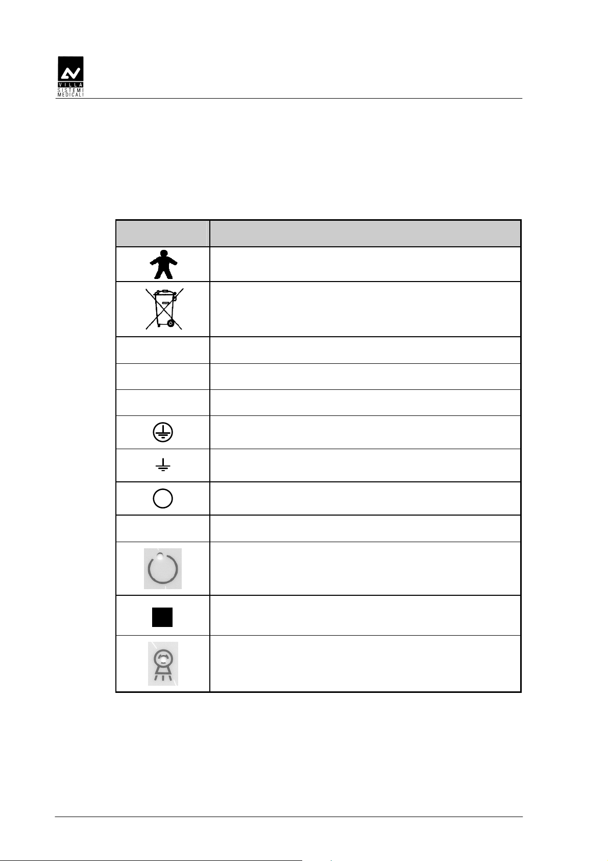
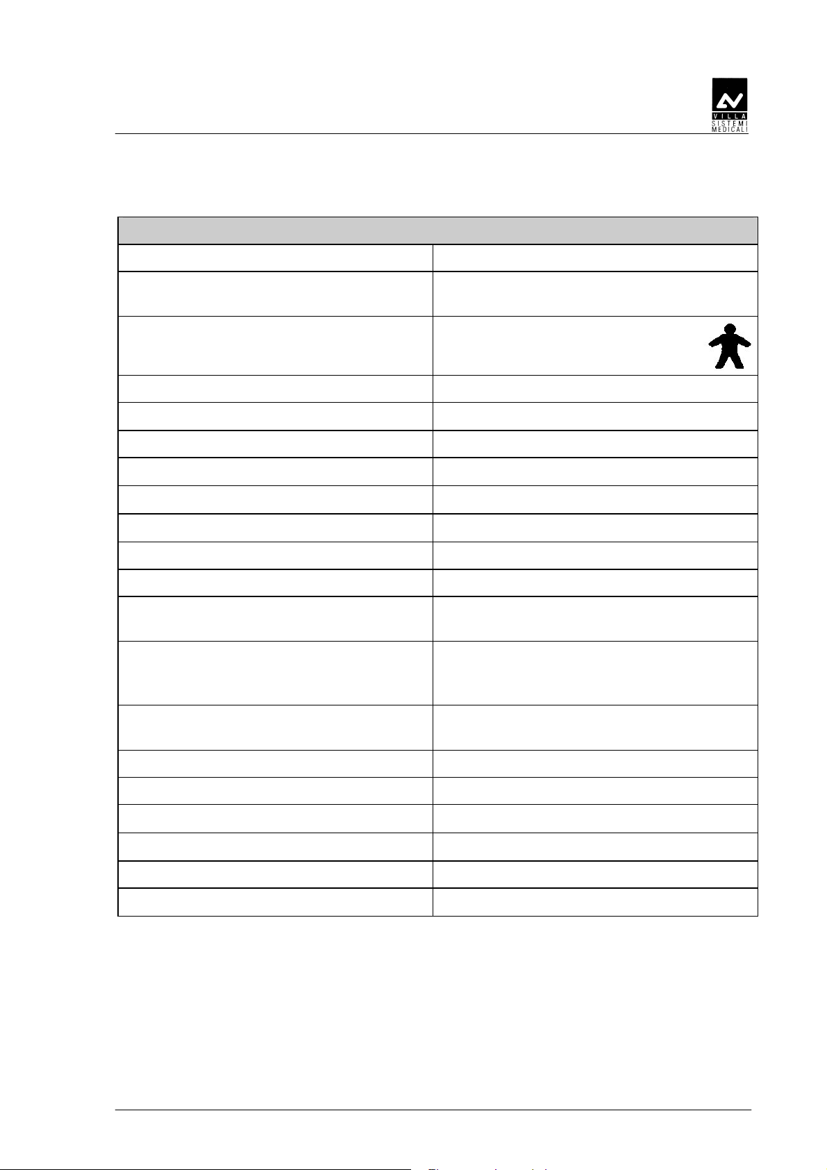
The following symbols are used in this manual and in ENDOS AC/ACP,
besides the symbols on the keyboard (see chapter 6 of User's Manual):
Symbol Description
Equipment with applied parts Type B
A number of machine parts contain materials and
liquids that upon completion of the machine’s life
cycle must be disposed of at recovery centers
established by the local health units
SERVICE MANUAL
Safety aspects
∼∼∼∼
N Connecting point to neutral conductor
L Connecting point to live conductor
Alternate current
Protection ground
Functional ground
OFF ; equipment not connected to electricity line
ON ; equipment connected to electricity line
Permission key to exposure; the permitted exposure
status is displayed by switching on the corresponding
green symbol
Focal spot according to IEC 336
X-ray emission
ENDOS AC/ACP - CE (Rev. 6)
6

SERVICE MANUAL
Description
3.
3. DESCRIPTION
3.3.
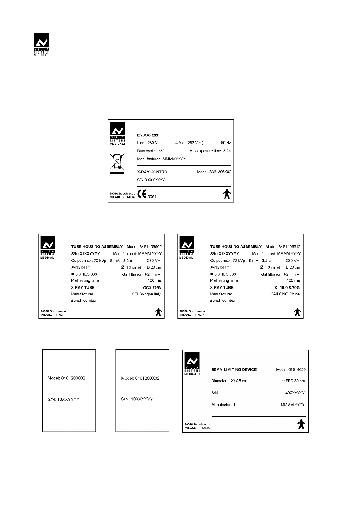
3.1
3.1 Identification labels
3.13.1
DESCRIPTION
DESCRIPTIONDESCRIPTION
Identification labels
Identification labelsIdentification labels
1
3
4
2
(Rev. 2) ENDOS AC/ACP - CE
7
SERVICE MANUAL
Description
1
ENDOS AC/ACP
label
2a
Tubehead label
(X-ray tube type CEI)
3
DP arm
label
4
Extension arm
label
2b
Tubehead label
(X-ray tube type KAILONG)
5
Collimator 30 cm (optional)
label
ENDOS AC/ACP - CE (Rev. 6)
8
SERVICE MANUAL
Description
3.2
3.2 Functions, Models and Versions
3.23.2
3.2.1
3.2.1 Extension arm and scissors arm
3.2.13.2.1
Functions, Models and Versions
Functions, Models and VersionsFunctions, Models and Versions
ENDOS AC/ACP intraoral radiographic equipment is composed of the
following parts:
Extension arm and scissors arm
Extension arm and scissors armExtension arm and scissors arm
It is composed of a double articulated joint arm, enabling extension
horizontally and vertically. The tubehead is balanced in all positions.
NOTE:
The scissors arm is designed to work correctly at a max. angle of 160°; so
*
its use requires a flare angle of less than 160°.
Moreover, a horizontal extension arm can be added, available in various
sizes, to meet all requirements.
3.2.2
3.2.2 Tubehead
3.2.23.2.2
Tubehead
TubeheadTubehead
The 70 kVp voltage, the 8 mA current and the use of a tube with grid
reduce exposure times and the quantities of X-rays absorbed by the
patient. The radiogenic equipment is provided with a collimator with 20
cm focus skin distance and a 6 cm X-ray emission diameter at the exit of
the cone. The tubehead is connected to the arm by a guide, which allows
360° horizontal rotation and 290° vertical rotation.
Two alternate X-ray tubes can be used: both have the same
characteristics and provide the same performance.
The tubehead assembled with different X-ray tubes are interchangeable
so long as preheating time is set to the proper value indicated on the
tubehead label (see chapter 8).
(Rev. 2) ENDOS AC/ACP - CE
9
3.2.3
3.2.3 Timer
3.2.33.2.3
Timer
TimerTimer
The name of ENDOS AC/ACP depends on the type of timer in use:
• ENDOS ACP
ENDOS ACP
ENDOS ACPENDOS ACP
ENDOS ACP is a digital timer with microprocessor where exposure
times can be selected both manually and automatically.
With automatic selection there is a choice of 30 pre-set times
depending on the patient’s size (small, medium or large) and the type
of tooth and acquisition mode (film, digital).
There are 33 fixed manual selection times that vary from a minimum
of 0.02 seconds to a maximum of 3.20 seconds.
The main feature of this timer is that it has an automatic exposure
time compensation for drift of nominal voltage within ± 10%.
• ENDOS AC
ENDOS AC
ENDOS ACENDOS AC
ENDOS AC has the same features as the ENDOS ACP timer,
excluding automatic and digital anatomic selection.
It has manual exposure time selection only.
NOTE:
A remote X-ray button configuration can be made, outside the exam
*
room. This can be a pure door bell X-ray button or a device which also
show status of the unit ("READY" and "EXPOSURE IN PROGRESS").
NOTE:
The equipment supplies two separate contacts for connection with
*
external signalling devices. One contact shows the status of functioning
equipment ready for use and the second one the X-ray emission.
Connection procedures and the necessary requisites for signalling
devices are given in the paragraph 5.2.
SERVICE MANUAL
Description
ENDOS AC/ACP - CE (Rev. 3)
10
SERVICE MANUAL
Description
3.3
3.3 Configurations
3.33.3
3.3.1
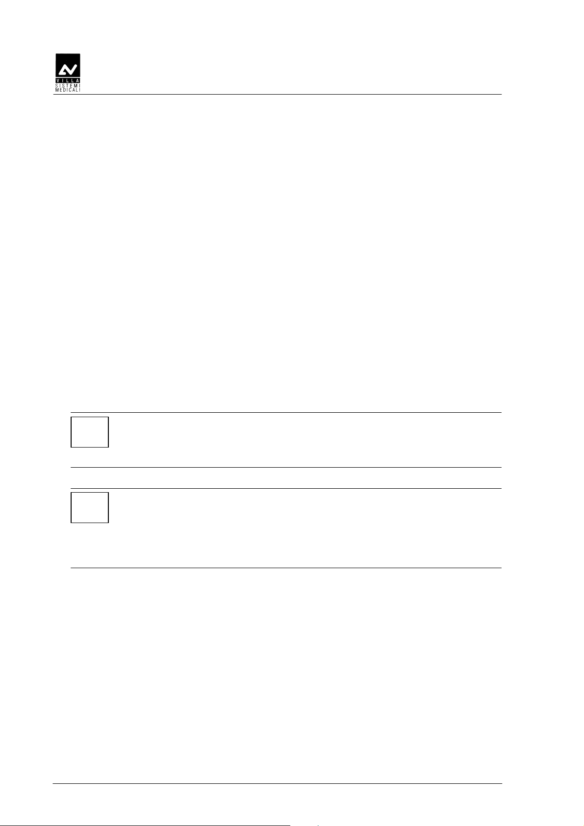
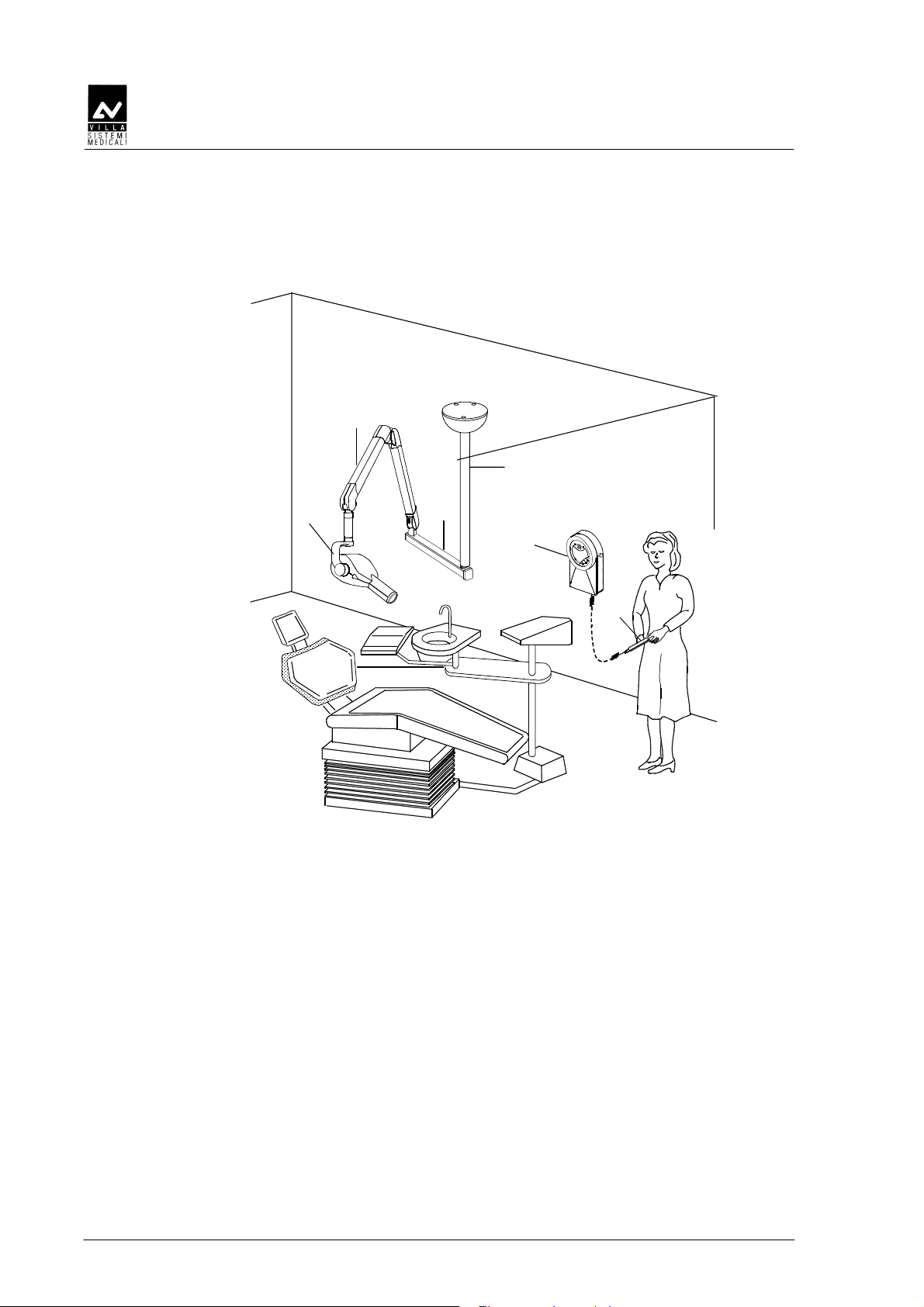
3.3.1 Standard configuration
3.3.13.3.1
Configurations
ConfigurationsConfigurations
Standard configuration
Standard configurationStandard configuration
2
1
4
5
3
Figure 3-1
1 Tubehead
2 Scissors arm
3 Extension arm
4 Timer
5 X-ray button
(Rev. 2) ENDOS AC/ACP - CE
11
3.3.2
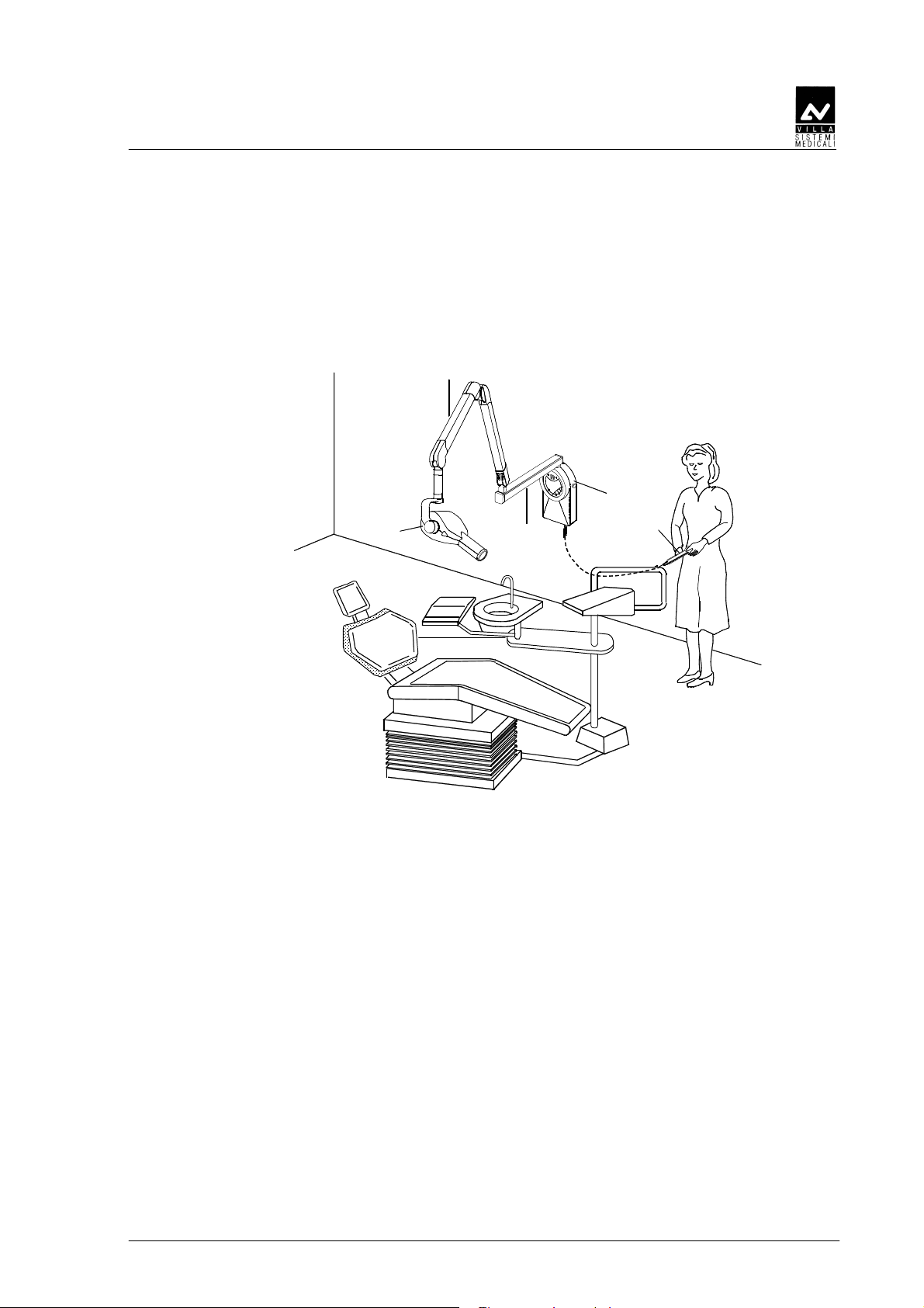
3.3.2 Remote timer configuration
3.3.23.3.2
Remote timer configuration
Remote timer configurationRemote timer configuration
2
SERVICE MANUAL
Description
1
4
5
3
6
Figure 3-2
1 Tubehead
2 Scissors arm
3 Extension arm
4 Wall support (kit code 8161301002)
5 Remote timer
6 X-ray button
ENDOS AC/ACP - CE (Rev. 3)
12
SERVICE MANUAL
Description
3.3.3
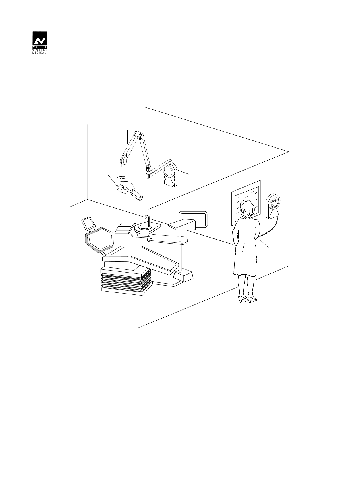
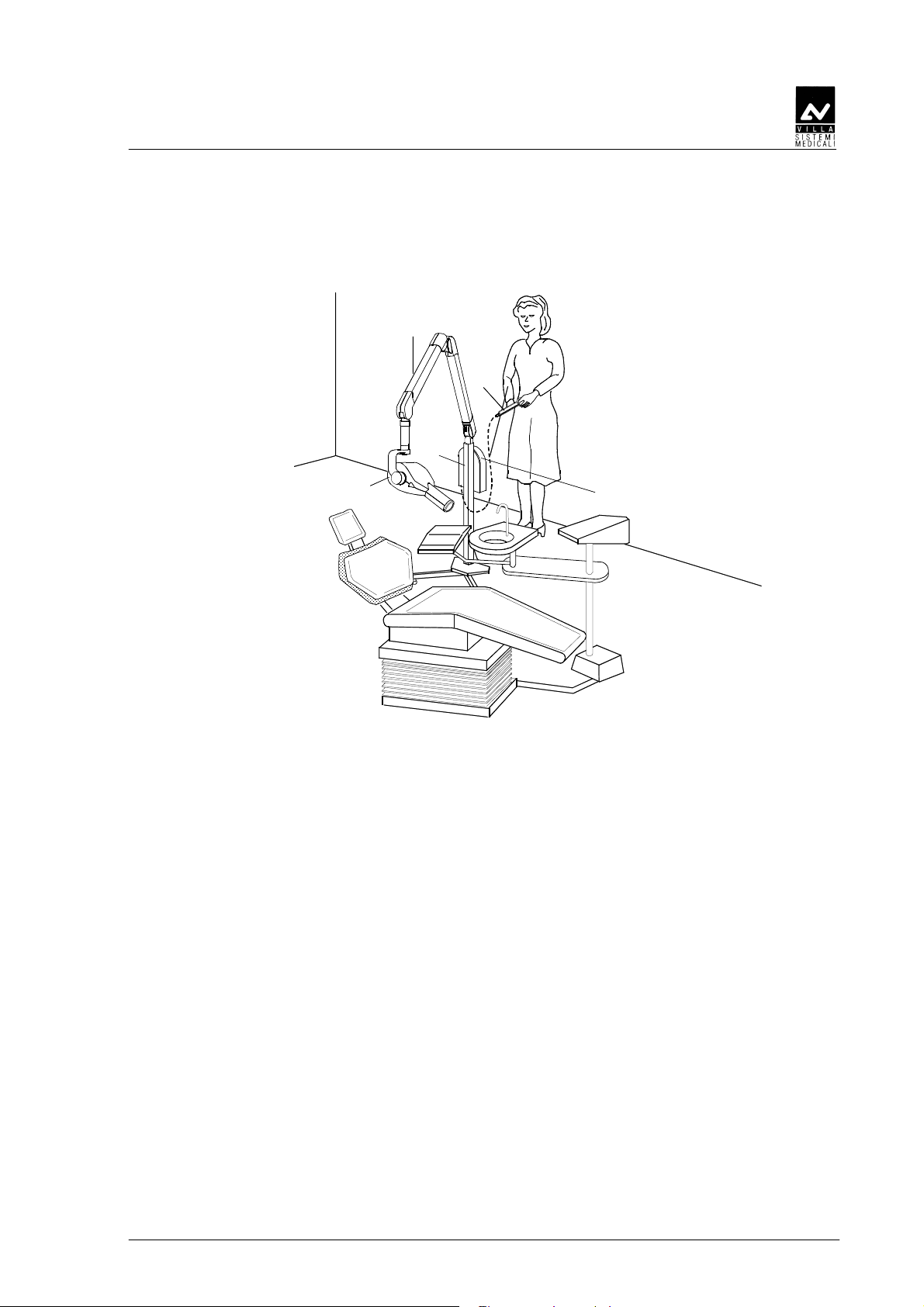
3.3.3 Dental chair configuration
3.3.33.3.3
Dental chair configuration
Dental chair configurationDental chair configuration
2
1
5
3
6
4
Figure 3-3
1 Tubehead
2 Scissors arm
3 Dental chair extension arm 30 cm
4 Dental chair connection
5 Timer
6 X-ray button
NOTE:
For this configuration Villa Sistemi Medicali supplies the scissors arm
*
and the 30cm extension arm, but not the support of the extension arm
which is provided with a ∅ 28mm h7 (+0 / -0.021), 110mm long pin. The
weights of the components forming the equipment are shown in the
chapter 4.
Villa Sistemi Medicali is not responsible for any damage to the
operator or to the patient deriving from wrong assembly or from
inadequate resistance of the supports in the joined part.
(Rev. 2) ENDOS AC/ACP - CE
13
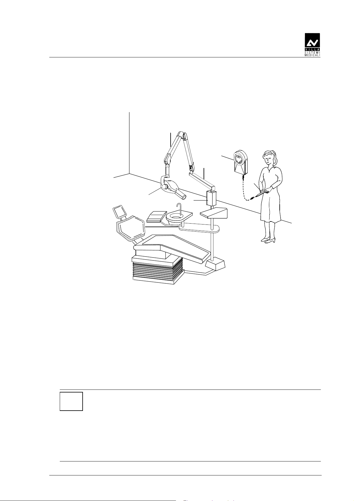
3.3.4
3.3.4 Ceiling configuration
3.3.43.3.4
Ceiling configuration
Ceiling configurationCeiling configuration
2
SERVICE MANUAL
Description
4
1
3
5
6
Figure 3-4
1 Tubehead
2 Scissors arm
3 Ceiling extension arm
4 Ceiling suspension
5 Timer
6 X-ray button
ENDOS AC/ACP - CE (Rev. 3)
14
SERVICE MANUAL
Description
3.3.5
3.3.5 Mobile stand configuration
3.3.53.3.5
Mobile stand configuration
Mobile stand configurationMobile stand configuration
2
5
3
1
4
Figure 3-5
1 Tubehead
2 Scissors arm
3 Mobile stand
4 Timer
5 X-ray button
(Rev. 2) ENDOS AC/ACP - CE
15
3.3.6
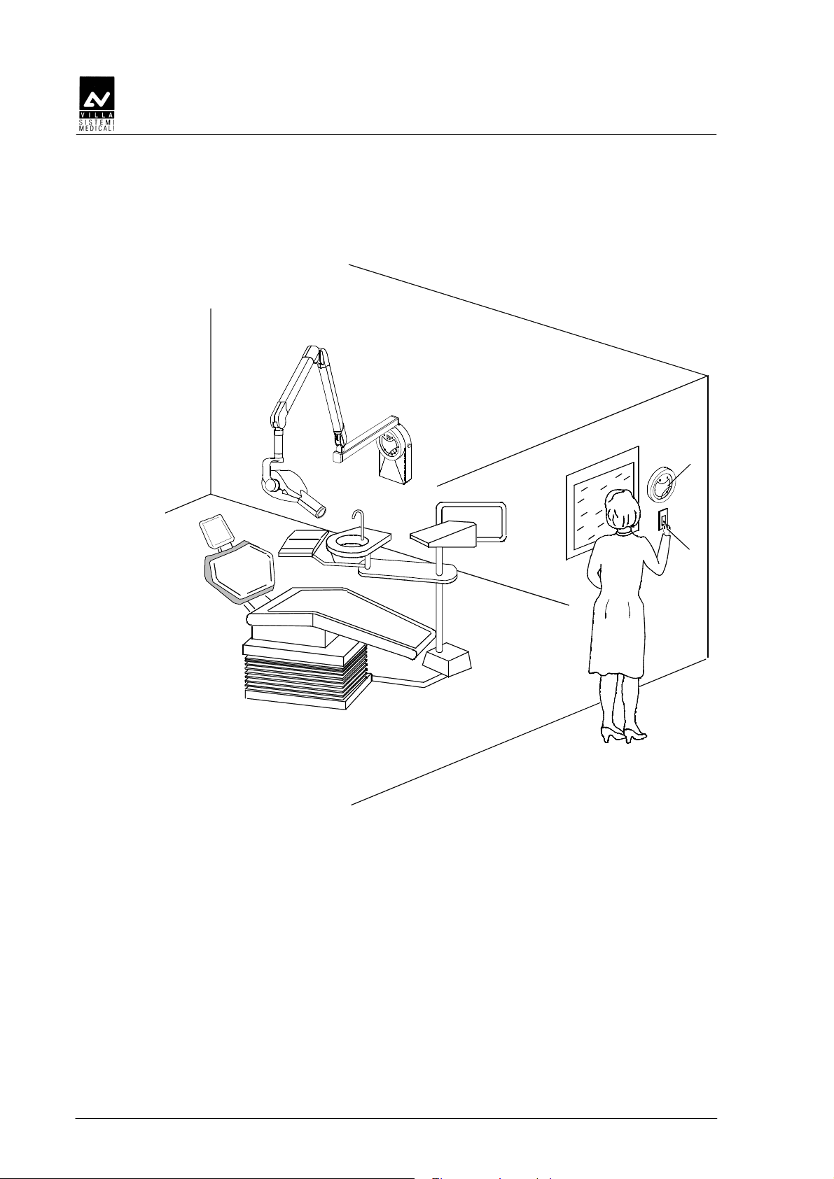
3.3.6 Remote X
3.3.63.3.6
Remote X----ray butt
Remote XRemote X
ray button configuration
ray buttray butt
on configuration
on configurationon configuration
SERVICE MANUAL
Description
2
1
Figure 3-6
Alternative 1:
1 X-ray button (not supplied)
Alternative 2:
2 X-ray button + light signalling of "Ready"
or "Exposure in progress" (supplied as kit
P/N 6661309500)
ENDOS AC/ACP - CE (Rev. 3)
16
SERVICE MANUAL
Technical data
4.
4. T
4.4.
Technical features
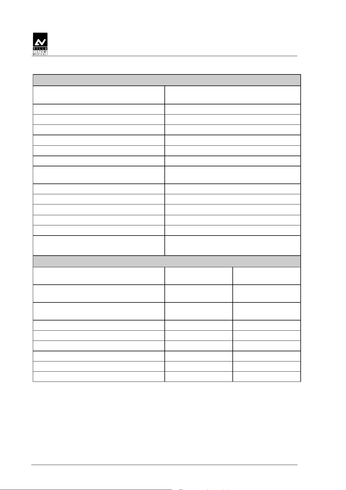
Equipment ENDOS AC/ACP
Manufacturer VILLA SISTEMI MEDICALI
TECHNICAL DATA
ECHNICAL DATA
TT
ECHNICAL DATAECHNICAL DATA
Buccinasco (MI)
Class
Protection level Standard Apparatus IP20
Line voltage
Line frequency 50 Hz
Absorbed current
Power consumption
Max. apparent line resistance
Main fuse 6 AF
Pre-set exposure times from 0.02 to 3.2 s in 33 steps
Automical selection
(only for ENDOS ACP)
Exposure time accuracy
Circuit type Single phase self-rectifying with grid
Class I° with type B applied parts
(EN 60601-1 classification)
230 V∼ ± 10%
4 A rms impulsive @ 230 V ∼
920 VA impulsive @ 230 V ∼
0.8 Ω max.
30 pre-set times
± 10% or ± 20 ms
(whichever is greater - see note
paragraph 4.5)
control
kV selection (high voltage value) 70 kVp
Tubehead current 8 mA
KV accuracy
Tubehead (anode) current accuracy
Max. exposure time 3.2 s
Timer dimension
(Rev. 2) ENDOS AC/ACP - CE
± 6 % @ nominal voltage
± 13 % @ nominal voltage
345×195×100 mm
17
SERVICE MANUAL
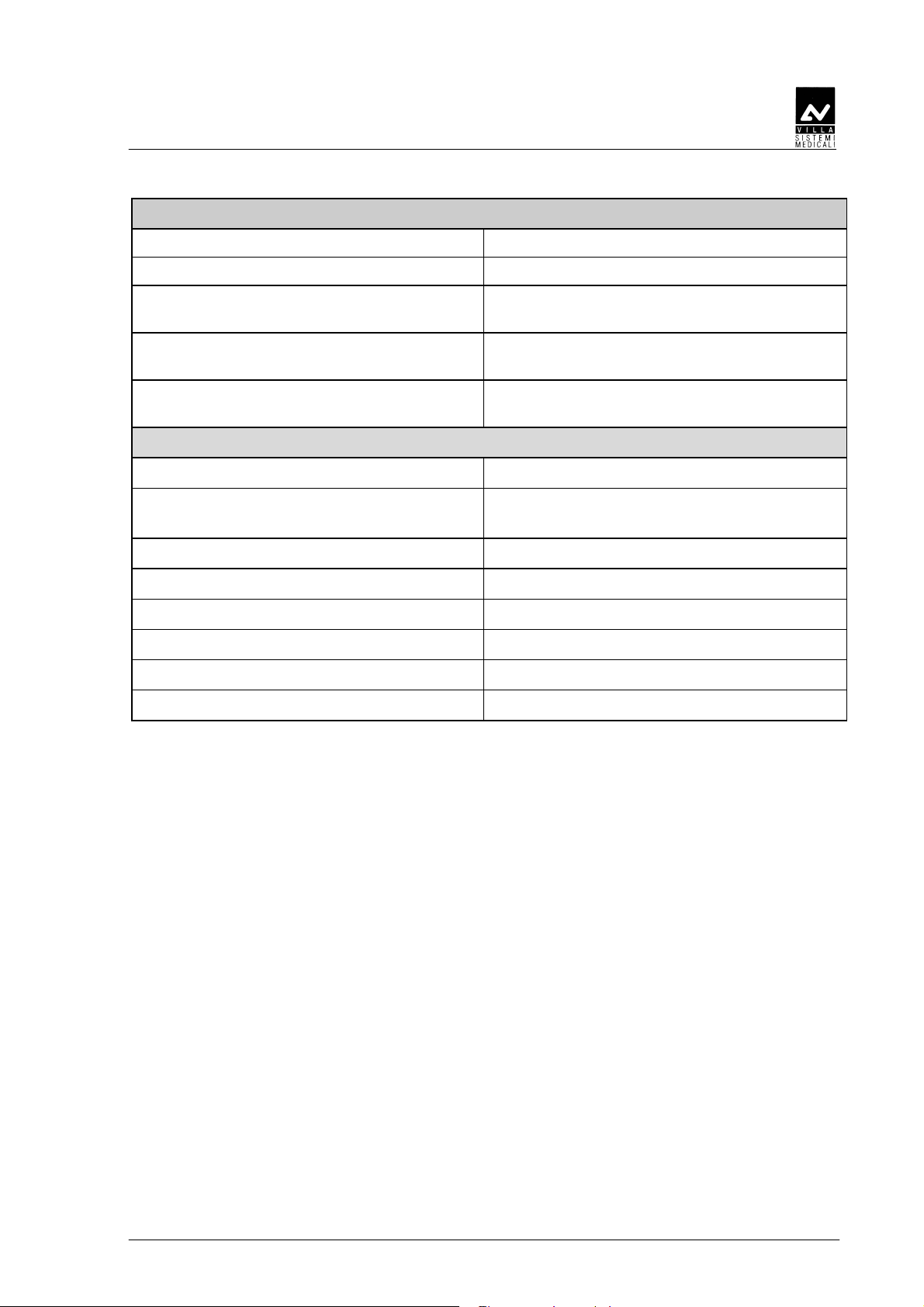
Tubehead features
Manufacturer VILLA SISTEMI MEDICALI
Buccinasco (MI)
Rated voltage 70 kVp
Tubehead power 430 W
Pre-heating time 100 ms
Technical data
Total filtration
≥ 2 mm Al eq. @ 70 kV
HVL (Half Value Layer) > 1.5 mm Al eq.
Transformer insulation Oil bath
Interval between exposures /
duty cycle
32 times X–ray time /
1 : 32
Focal spot 0.8 (IEC 336)
Minimum focus to skin distance 20 cm (optional 30 cm cone)
X-ray beam diameter (@ 20cm focus)
≤ 6 cm (optional 35x45 mm)
Cooling Convection
Radiation leakage at 1 m < 0.1 mGy/h
Technical factors for radiation leakage 70 kV, 8 mA, 1 s duty cycle
1 exposure each 32 seconds
X-ray tube features
Manufacturer CEI Bologna
(Italy)
Type OCX/ 70-G
KAILONG Electronic
(China)
KL16 - 0.8 - 70G
with grid
Inherent filtration 0.5 mm Al
equivalent to 70 kV
0.4 mm Al
equivalent to 70 kV
Anode tilt 19° 19°
Anode material Tungsten Tungsten
Rated voltage 70 kV 70 kV
Maximum filament current 2.8 A 2.8 A
Maximum filament voltage 4 V 4.1 V
Anode thermal capacity 6 kJ 7 kJ
ENDOS AC/ACP - CE (Rev. 3)
18
SERVICE MANUAL
Technical data
Environmental conditions
Operating temperature range
Operating relative humidity range
Temperature range for transport and
+10°C ÷ +40°C
30% ÷ 75%
-20°C ÷ +70°C
storage
Max. relative humidity for transport and
<95 % non condensing
storage
Min. atmospheric pressure for storage
630hPa
and transport
Apparatus and detachable parts weight
Gross weight including packing 30.4 kg
Net apparatus weight in standard
25.4 kg
configuration
60 cm extension arm (standard) 2.9 kg
80 cm extension arm 3.5 kg
30 cm extension arm 1.9 kg
Scissors arm 9 kg
Timer plus wall plate 5 kg
Tubehead 8.5 kg
(Rev. 2) ENDOS AC/ACP - CE
19

4.1
4.1 Method for correcting exposure times
4.14.1
Method for correcting exposure times
Method for correcting exposure timesMethod for correcting exposure times
This RX intraoral equipment features a special function called Computer
Controlled Density which makes it possible to correct exposure time
automatically when line voltage is different from its nominal voltage.
A change in the line voltage affects the peak voltage applied to the RX
tube and the high voltage value affects the Rx spectrum very
significantly. This, in turn, affects the optical density of the image on the
film. The task of the correction is to achieve the same optical image
density irrespective of the variations in line voltage, within its permitted
variation range of ± 10%. In short, this feature makes it possible to
obtain the same quality of image without having to be concerned about
possible line variations which occur frequently in many areas and which
are almost impossible to prevent without resorting to costly equipment.
Automatic exposure time correction works with the following sequence:
inside the timer there is a voltmeter which takes a constant reading of
the line voltage, while the user selects the desired exposure time. After
the user has chosen the exposure time he knows from experience to be
the best for the type of X-ray he is going to take, the user himself presses
the key enabling exposure and the timer shows on the screen the correct
time that will be used for the exposure in progress, time that the timer
itself has calculated according to the value of the line voltage measured
an instant before pressing the key of the exposure permission.
NOTE:
ENDOS AC and ENDOS ACP timers work in step with the line frequency,
*
so the calculated time is always rounded off to the multiple of the line
frequency itself.
The correct exposure time shown once the timer has been enabled by the
"Ready" key and during the execution of the X-ray is the time actually
used by the equipment: it is calculated applying a correction factor to the
time selected by the user, based on the empirical law relating to the
optical density of the film with the high voltage peak value and
consequently with the line voltage.
NOTE:
If the "Ready" key has been disabled in system configuration, the display
*
will show the "corrected" exposure time only during exposure or holding
the X-ray button pressed at the end of it.
SERVICE MANUAL
Technical data
ENDOS AC/ACP - CE (Rev. 4)
20

SERVICE MANUAL
Technical data
The qualitative relation between the multiplication factor and the line
voltage is shown in the following picture (for equipment configured to
work at 230V):
Multiplication factor
of exposure time to
the variation of line
voltage
1,75
1,5
1,25
1
0,75
0,5
206 218 230 242 254
Line voltage
(Rev. 2) ENDOS AC/ACP - CE
21

SERVICE MANUAL
Technical data
4.2
4.2 Method for measuring technical factors
4.24.2
kV
KVp value is defined as the stationary value of high voltage applied to
p
mA The anodic current value is defined as the average value of stationary
t The exposure time value is the time during which the value of the anodic
Method for measuring technical factors
Method for measuring technical factorsMethod for measuring technical factors
the tube which settles on load after preheating time.
KV
value is measured by a non-invasive instrument, with accuracy of
p
over 2%, to the nominal value of line voltage.
A direct high voltage measurement can be made only by disassembling
the tubehead. This operation can be executed only in the factory.
current which settles on load after pre-switching time.
The anodic current value is measured using a digital voltmeter
measuring the voltage drop at the ends of the resistance from 1 kΩ, 1%
assembled on the tubehead. To take this measurement, remove the side
plastic plug of the tube support; connect the ground voltmeter terminal
on the yellow/green cable clamp screw and insert the positive terminal
into the contact at the end of the grey cable. The digital voltmeter must
be selected on DC, and the relation of transformation is given by 1 mA =
1V. Execute an exposure of at least 1 sec.
peak current exceeds 25% of the steady state value. The time taken to
reach this condition is called "pre-heating time".
The measurement must be taken at nominal line voltage, measuring the
anodic current wave-form on the 1kΩ resistance and using a memory
oscilloscope.
Exposure time measurements using non-invasive equipment can
lead to systematic errors in exposure time measurements which
cannot be quantified and which depend on the equipment used for
measuring (see paragraph 4.3).
ENDOS AC/ACP - CE (Rev. 3)
22
SERVICE MANUAL
Technical data
4.3
4.3 Correct use of dosimeters to measure exposure
4.34.3
Correct use of dosimeters to measure exposure
Correct use of dosimeters to measure exposure Correct use of dosimeters to measure exposure
times
times
timestimes
The spread of non-invasive equipment to measure the functional
parameters of RX equipment has introduced a series of interpretation
problems when measuring exposure times.
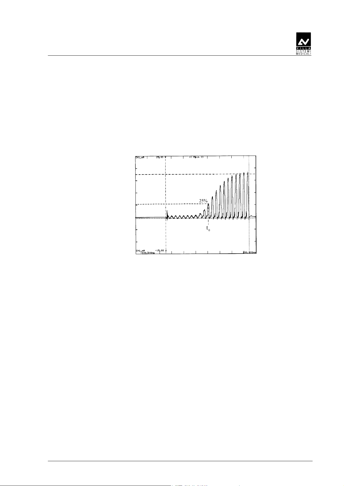
The source of the problem is in the characteristic rise curve of the RX
tube’s anodic current which is represented in the picture:
Anodic
current
According to IEC60601-2-7 (1998) regulations, "in equipment where the
filament is switched on and high voltage is applied simultaneously, the
exposure time is calculated as the interval between the instant when the
anodic current exceeds 25% of the nominal value and the instant when
it goes below such value".
This method is defined as invasive because it requires that the anodic
current flowing through a resistance inside the tubehead must be
measured.
Non-invasive methods are definitely easier and faster compared with the
invasive method, but they are prone to errors which can be considerable
when determining exposure time. In fact some of these devices start
counting exposure time as soon as a small quantity of radiation reaches
the measuring chamber with the result that they take longer times than
the ones determined by the invasive method applied by the
manufacturer.
Consequently, calculations obtained by these non-invasive methods can
erroneously lead to the conclusion that the equipment timer is not
accurate. Actually the difference is connected to the method adopted in
measuring the exposure time.
Time
(Rev. 2) ENDOS AC/ACP - CE
23

SERVICE MANUAL
Technical data
By using a tube with grid it is possible to reduce to the minimum the
time required for the anodic current, and as a consequence, the dose
adjustment to reach the steady state, so there is very little difference
between the exposure time measurement using the invasive and the non
invasive method.
Corrective actions
A practical method can be applied to get round the problem which can
be described this way:
• In a graph you report the values of times measured using the
equipment compared with the ones displayed by the timer
(automatically corrected for the line variations): the dots of the graph
are interpolated with a straight line (if possible by the least square
method or more simply in a graphic way).
• You determine the intercept on the Y axis of this straight line: this
can be assumed as the time value that the non-invasive device adds
to each measurement due to the radiation which reaches the device
before the anodic current is 25% of its maximum value.
• Then you subtract this "offset" time from all the device measurements
and you proceed with comparing the time measurements displayed
by the timer.
ENDOS AC/ACP - CE (Rev. 3)
24
SERVICE MANUAL
Technical data
4.4
4.4 Curves tube features
4.44.4
Curves tube features
Curves tube featuresCurves tube features
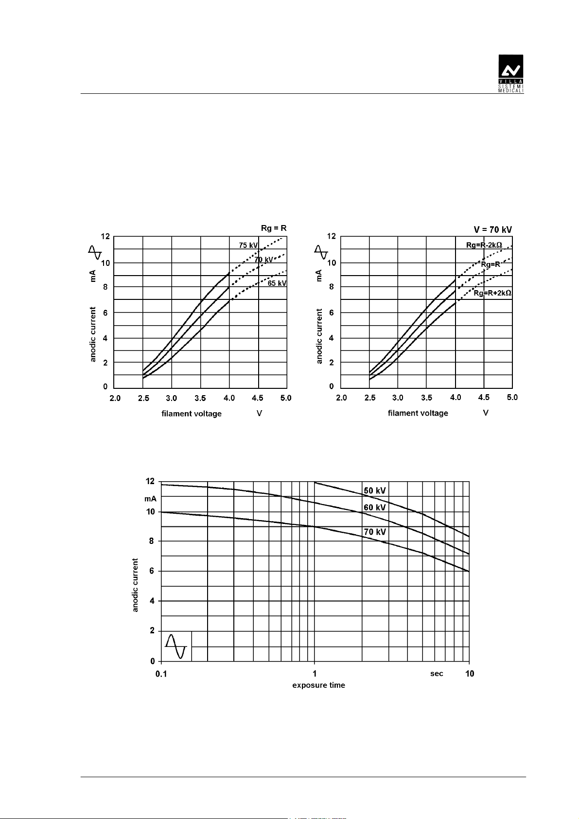
OCX / 70-G
Feature of emission
Load
(Rev. 2) ENDOS AC/ACP - CE
25
 Loading...