

Viking vr-1a Service Manual

Telecommunication Peripheral Products
VR-1A
Universal Visual
Indicator
Technical Practice
June 20, 2001
Provide Line Status and Message
Waiting Indication
When used with an analog phone line, the VR-1A will
provide “ring” indication, “on the phone” indication and
“message waiting” indication for both “stutter dial tone”
and standard message waiting voltage. In this
application the VR-1A connects directly to tip and ring.
When used with electronic or digital phones, the VR-1A
won’t have you guessing which phone is ringing in busy
offices. The flashing LED can be seen up to 100 feet
away. The VR-1A connects directly to the electronic
phone’s speaker.
When used with a headset, you can end those nagging interruptions that occur when
associates’ don’t realize you are on the phone because you are using a headset. The
VR-1A will flash twice indicating to everyone that you are on the phone and you are
not to be disturbed. The VR-1A installs in the handset/headset jack using an included
“T” adapter.
VIKING©
http://www.VikingElectronics.com
E-mail...Sales@VikingElectronics.com
Features Applications
• Displays “ringing,” “on-the-phone” or “message
waiting”
• LED visible up to 100 ft
• Power supply included
• Compact package mounts with double-backed
tape
• Connects with modular cord
• Special “T” adapter provided for handset
applications
Sales...(715) 386 - 8861
Made in the U.S.A.
• Call centers
• Telemarketing
• Product support groups
• Office cubicles
• C.O. based voice messaging
• Purchasing departments
• Sales offices
Specifications
Power: 120V AC/12V DC 500mA UL listed adapter provided
Dimensions: 70mm x 50mm x 40mm (2.9” x 2.1” x 1.5”)
Shipping Weight:
Environmental: 0°C to 32°C (32°F to 90°F) with 5% to 95% non-
condensing humidity
Connections: (1) RJ14 jack
Light: 19mm (.75”) red LED
Visibility: 30m (100’) typical
Message Waiting Voltage: 90V - 125V
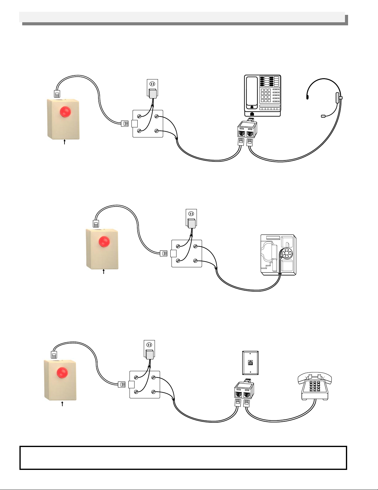
Installation/Applications
A. Headsets
Connect the receive pair (typically the inside pair) of an Electronic or Digital phone handset jack, using the special
“T” adapter provided, to the red and green wires of a modular telephone jack assembly as shown below. Connect
the 12V DC power supply to the yellow and black wires. When audio going to the handset or headset is detected,
the VR-1A will flash to show others that you are on the phone.
120V AC
Yellow Black
VR-1A
Telephone jack assembly
Adjust the sensitivity with the trim
pot if necessary. Turn clockwise
to increase sensitivity.
Radio Shack part # 279-355
or Suttle part # SE-625A4
Red
Green
(Cord not included)
B. Electronic and Digital Phones
Connect the speaker leads of an Electronic or Digital phone to the red and green and connect the 12V DC power
supply to yellow and black using a modular telephone jack assembly as shown below. The speaker may be
disconnected if a resistor of equal value is substituted. The VR-1A will flash to indicate ringing.
Electronic/Digital Phone
“T” adapter to handset
jack on phone
Headset
VR-1A
Adjust the sensitivity with the trim
pot if necessary. Turn clockwise
to increase sensitivity.
C. Analog Phones
120V AC
Yellow Black
Telephone jack assembly
Radio Shack part # 279-355
or Suttle part # SE-625A4
Green
Red
(Cord not included)
Internal view of a
typical key set
telephone
Connect tip and ring to the green and red and connect the 12V DC power supply to yellow and black using a
modular telephone jack assembly as shown below. The VR-1A will flash to indicate ringing, light steady when the
phone is off hook, follow the cadence of 90 to 125V message waiting voltage and gives a “stutter” flash if message
waiting “stutter” dial tone is detected.
120V AC
Yellow Black
VR-1A
“T” adapter
Standard Analog Phone
Telephone jack assembly
“Stutter” dial tone detection may
require adjusting sensitivity.
Start with the trim pot in the
center position.
Radio Shack part # 279-355
or Suttle part # SE-625A4
Red
Green
(Cord not included)
Product Support Line...(715) 386-8666 Fax Back Line...(715) 386-4345
Due to the dynamic nature of the product design, the information contained in this document is subject to change without notice. Viking
Electronics, its affiliates and/or subsidiaries assume no responsibility for errors and/or omissions contained in this information. Revisions of
this document or new editions of it may be issued to incorporate such changes.
Printed in the U.S.A. ZF300370 Rev CFax Back Doc # 695
 Loading...