

Page 1
Viking Installation & Usage Guide
U
L
C
U
L
Viking Range Corporation
111 Front Street
Greenwood, Mississippi 38930 USA
(662) 455-1200
For product information,
call 1-888-VIKING1 (845-4641)
or visit the Viking Web site at
vikingrange.com
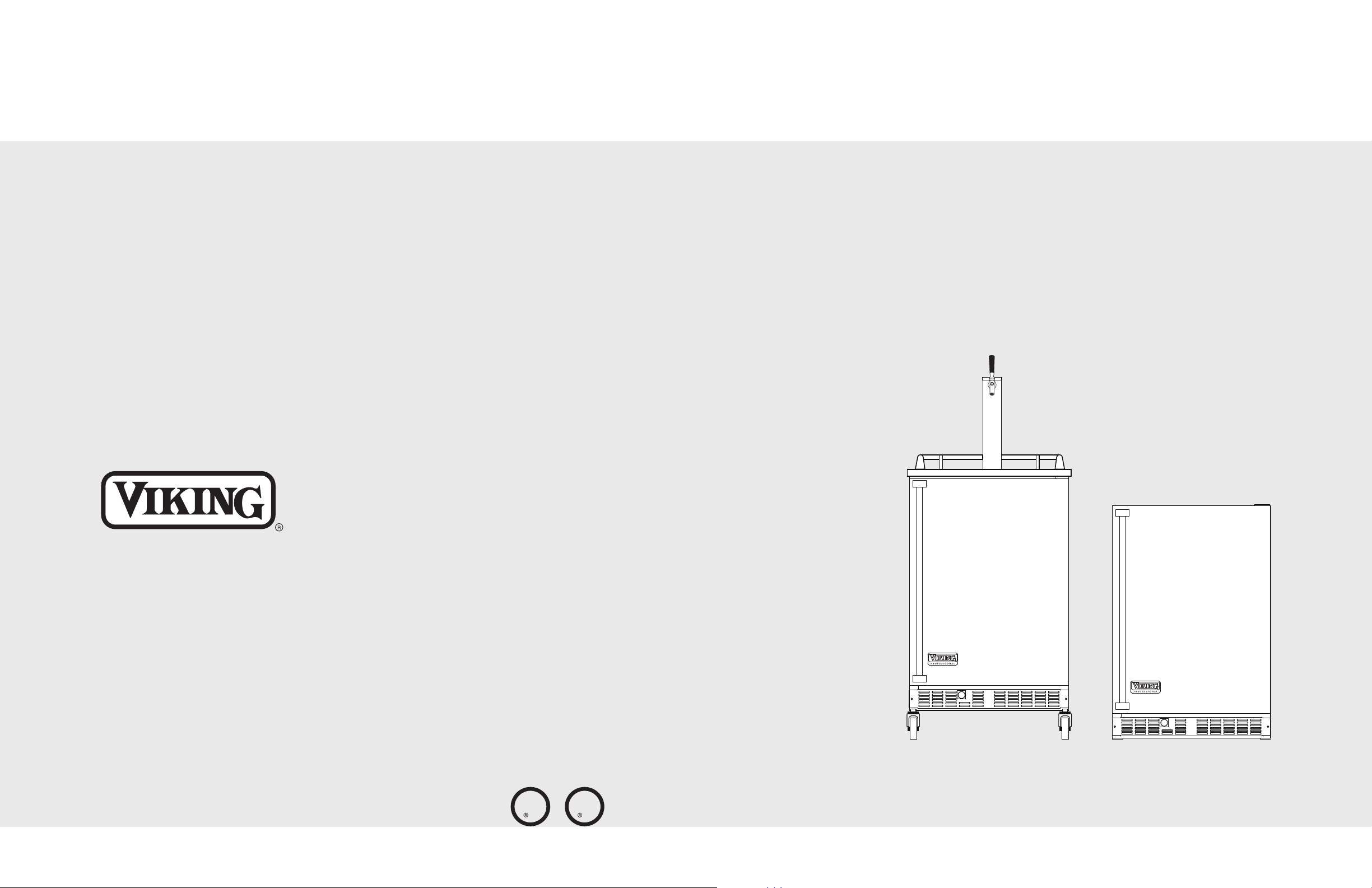
Built-In/Portable 24”W. Beverage Dispensers
F1755K EN
(071610)
Page 2
Table of Contents
IMPORTANT3– Please Read and Follow
Warnings & Important Information _____________________________________________________3
Unpacking & Features ________________________________________________________________4
Proper Disposal _____________________________________________________________________5
Installation Location & Wiring _________________________________________________________6
Installation - Portable Models VRBD ___________________________________________________7
Dimensions - Portable Models _____________________________________________________8
Installation - Undercounter Models VUBD_______________________________________________9
Dimensions - Undercounter Models _______________________________________________10
Assembly __________________________________________________________________________11
CO
Regulator _____________________________________________________________________13
2
Tapping Procedures_________________________________________________________________14
Drain Hose & Container _____________________________________________________________15
Final Preparation & Operation _______________________________________________________16
Drawing Beer ______________________________________________________________________17
Cleaning & Maintenance ____________________________________________________________18
Troubleshooting ____________________________________________________________________19
Service Information _________________________________________________________________20
Warranty __________________________________________________________________________21
Your safety and the safety of others is
very important.
We have provided many important safety
messages in this manual and on your
appliance. ALWAYS read and obey all
safety messages.
This is the safety alert symbol. This
symbol alerts you to hazards that
can kill or hurt you and others.
All safety messages will be preceded by
the safety alert symbol and the word
“DANGER,” “WARNING” or “CAUTION.”
These words mean:
DANGER
Hazards or unsafe practices
which WILL result in severe personal
injury or death
WARNING
Hazards or unsafe practices
which COULD result in severe personal
injury or death
CAUTION
Hazards or unsafe practices which
COULD result in minor personal injury
or property damage.
All safety messages will identify the
hazard, tell you how to reduce the chance
of injury, and tell you what can happen if
the instructions are not followed.
• Before beginning, please read these instructions
completely and carefully.
• Do not remove permanently affixed labels,
warnings, or plates from the product.
• The installer should leave these instructions with
the consumer for future reference.
• ALWAYS connect CO
valve or regulator.
• NEVER connect gas cylinder directly to keg.
• ALWAYS secure gas cylinder in upright
position.
• ALWAYS keep gas cylinder away from heat.
• NEVER drop or throw gas cylinder.
• ALWAYS ventilate after CO
• Gas cylinders should be stored in the coolest
part of the room, preferably at 70° F, and
securely fastened in the upright position
before the primary regulator is attached to
the cylinder.
gas cylinder to reducing
2
leakage.
2
WARNING
CO2CAN BE DANGEROUS
If it becomes difficult to breathe and
your head starts to ache, abnormal
concentrations of carbon dioxide may be
present in the area. Leave the room
immediately.
2
Page 3
Unpacking the Kit
1
2
3
5
4
6
7
8
9
10
Proper Disposal (of old refrigeration product)
Beer Dispensing Kit:
Unpack the kit and check contents.
You should receive:
1. Draft Tower Assembly
2. Drain Hose
3. Drain Container
4. Keg Coupler
5. Air Line with Clamps
6. Single Gauge Regulator
7. Filled 5 lb. CO2Gas Cylinder
8. Installation & Usage Guide
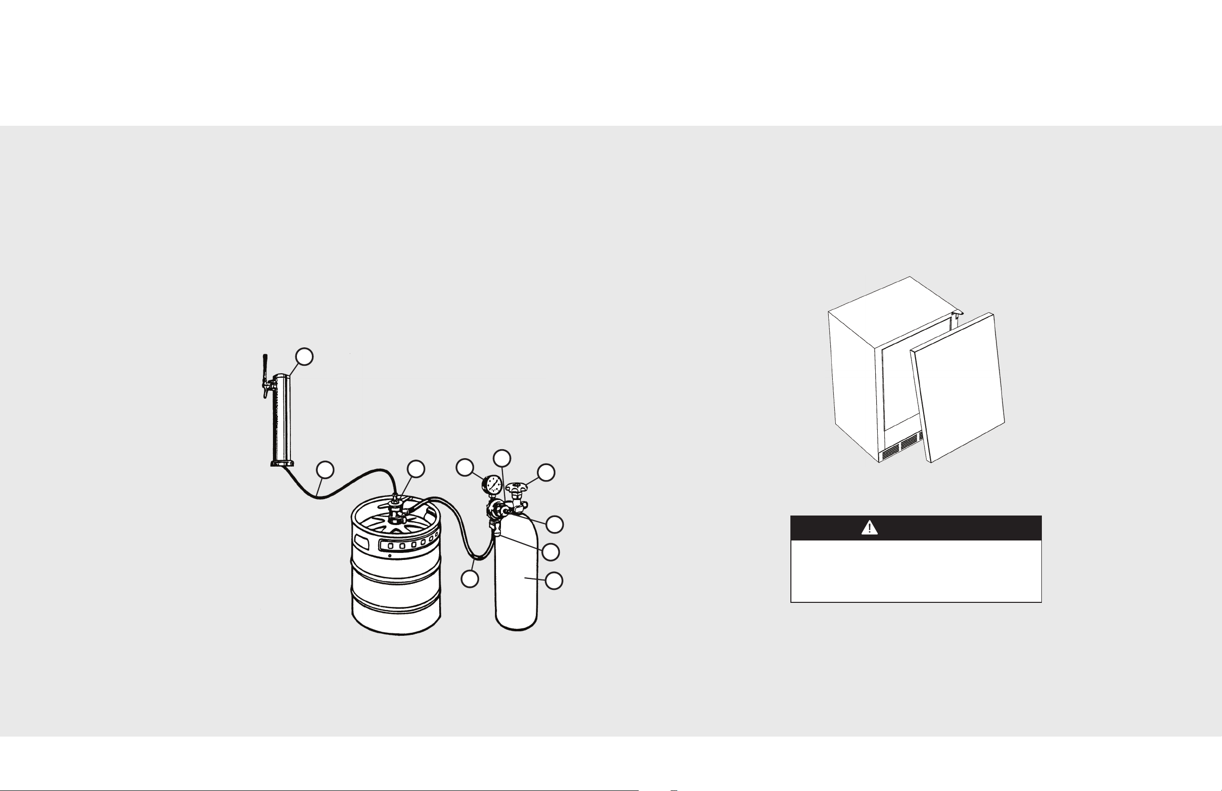
Features
1. Draft Tower Assembly
2. Beer Line
3. Keg Coupler (Sankey Type shown)
4. Regulator/Pressure Gauge
5. Regulator Coupling Nut
6. Drum Valve
7. Set Screw
8. Toggle Shut-Off Valve
9. CO2Tank
10. Air Line
Tools Needed:
• Crescent Wrench
• Pliers
• Screwdriver
IMPORTANT:
It is extremely important that you dispose of your old appliance in a way that minimizes the
possibility that children will find it. There have been many cases in years past of children crawling
inside junked and abandoned refigerators and becoming trapped or suffocated.
Contact your municipal waste disposal authority to find out the best and safest way to dispose of
your old refrigerator.
DANGER
RISK OF CHILD ENTRAPMENT
Before You Throw Away Your Old Refrigerator Product:
• Take off the doors.
• Leave the shelves in place so that children may not easily
climb inside.
4
5
Page 4
Installation Location & Wiring
Power Supply
with 3-prong
grounding plug
Grounding type
wall receptacle
2
4
”
(
6
1
.
0
c
m
)
24”
(
61.0 cm)*
24-3/4”
(62.9 cm)
35-9/16”
(90.3 cm)**
Installation
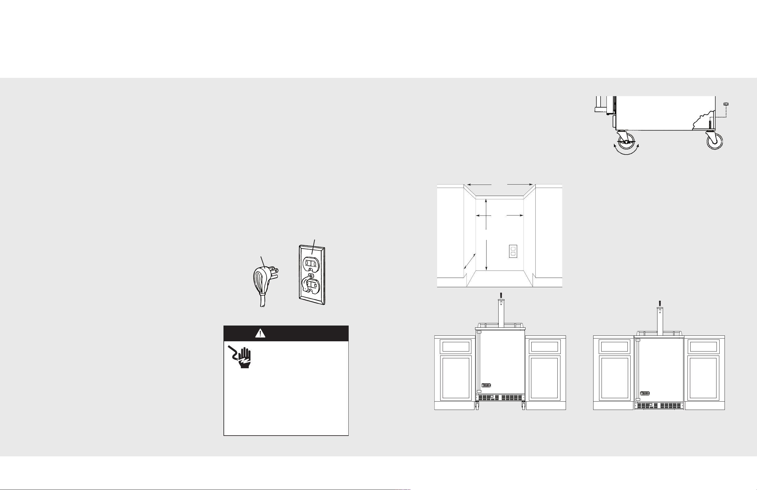
BUILT-IN INSTALLATION
Select Location
The proper location will ensure peak performance of your appliance. Choose a location where
the unit will be out of direct sunlight and away from heat sources. Units with fan cooled
condensers can be built-in.
Unit should be operated in a properly ventilated area with ambient temperatures above
40°F (4.4°C) and below 110°F (43°C). Installation should be such that the cabinet can be
moved for servicing if necessary.
Cabinet Clearance
Ventilation is required from the bottom front section of the unit. Keep this area open and clear
of any obstructions. The adjacent cabinets and countertop can be built around the unit as
long as no top trim or counter top is installed lower than the top of the hinge.
ELECTRICAL CONNECTION
Electrical Requirements
A 115 volt, 60 Hz, AC only 15 amp fused electrical supply is
required. (A time delay fuse or circuit breaker is recommended.)
It is recommended that a separate circuit, serving only this
appliance, be provided.
CASTERS
Your beverage dispenser is equipped with four casters.
The front two casters can be locked.
For built-in applications, the four casters can be
removed by removing the nut located inside the
dispenser cabinet and then pulling the threaded caster
spindle through the base of the unit.
Lock and Unlock
CABINET CUTOUT - PORTABLE MODELS - VRBD
*24” width for cabinet only. 24-1/4” (61.6 cm)
needed for cabinet and door width clearance
if door is recessed between cabinets.
**35-9/16” (90.3 cm) height is without casters
mounted to unit. 39-3/4” (101.0 cm)
needed for height clearance with casters.
• ELECTRICAL GROUND IS REQUIRED ON THIS APPLIANCE.
• DO NOT UNDER ANY CIRCUMSTANCES REMOVE THE
POWER SUPPLY CORD GROUND PLUG.
• DO NOT USE AN EXTENSION CORD.
Recommended Grounding Methods
For your personal safety, this unit must be grounded. This
appliance is equipped with a power supply cord having a
3-prong grounding plug. To minimize possible shock
hazard, the cord must be plugged into a mating 3-prong
grounding type wall receptacle grounded in accordance
with the National Electrical Code and local codes and
ordinances. If the circuit does not have a grounding type
receptacle, it is the responsibility and obligation of the
customer to exchange the existing receptacle in
accordance with the National Electrical Code and
applicable local codes and ordinances. The third ground
plug SHOULD NOT, under any circumstances, be cut or
removed. All UL listed refrigerated products are equipped
with this type of plug.
6 7
WARNING
ELECTRICAL SHOCK
HAZARD
Improper grounding can result in
a risk of electric shock.
Consult a qualified electrician if the
grounding instructions are not completely
understood, or if doubt exists as to
whether the appliance is properly
grounded. DO NOT use an extension
cord. If the power supply cord is too short,
have a qualified electrician install an outlet
near the appliance.
NOTE: If removing casters for installation, the unit should
be raised off the ground. This should be done with an
approved material. (Consult local building codes for
LEVEL UNIT
approved material.)
1. After placing unit in position, check to make certain that the unit is level side to side and front to back.
2. Accurate leveling is essential for proper operation.
Page 5
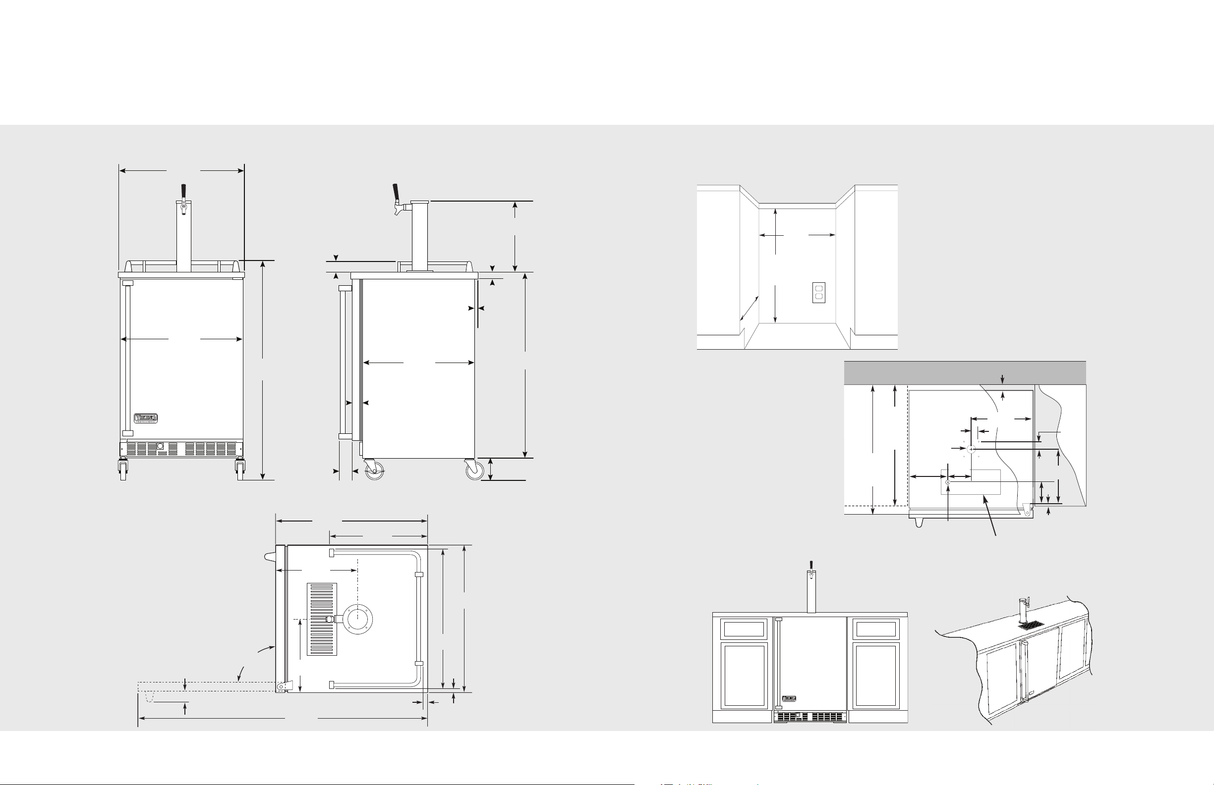
Dimensions - Portable Models VRBD
24-5/8”
(62.5 cm)
24”
(61.0 cm)
41-25/32”
(106.2 cm)
12-1/4”
(31.1 cm)
1-1/4”
(3.2 cm)
35-9/16”
(95.4 cm)
4-3/16”
(10.6 cm)
2-1/16”
(5.2 cm)
3/4”
(1.9 cm)
22”
(55.9 cm)
2-1/2”
(6.4 cm)
2-3/8”
(6.0 cm)
25-1/8”
(63.8 cm)
90°
24-5/8”
(62.5 cm
23-1/8”
(58.7 cm)
47-1/4”
(120.0 cm)
2-1/2”
(6.4 cm)
12-7/8”
(32.7 cm)
12-5/16”
(31.3 cm)
12-7/8”
(32.7 cm)
3/4”
(1.9 cm)
TYP
3/4”
(1.9 cm) TYP
2
4
”
(
6
1
.
0
c
m
)
24”
(61.0 cm)*
34-1/4”
(87.0 cm) min.
t
o
35”
(88.9 cm) max.
Rear wall
Countertop Countertop
25”
(63.5 cm)
Standard
Depth
24”
(61.0 cm)
Standard
Cabinet
Depth
1-1/2”
3.8 cm)
1-11/32”
(3.4 cm)TYP
1-11/32”
(3.4 cm)TYP
12”
(30.5 cm)
11”
(27.9 cm)
8”
(20.3 cm)
1/2”
(1.3 cm)
4”
(10.2 cm)
1-1/2”
(3.8 cm) dia.
3/4”
(1.9 cm) dia.
5”
(12.7 cm)
Front View Side View
Installation
CABINET CUTOUT - UNDERCOUNTER MODELS - VUBD
*24” width for cabinet only. 24-1/4”
(61.6 cm) needed for cabinet and
door width clearance if door is
recessed between cabinets.
Top View
8 9
Actual dimension of drain pan is 12” x 5”
(30.5 cm x 12.7 cm). This area should be cut
12-3/16” x 5-3/16” (31.0 cm x 13.2 cm) for
clearance.
Page 6
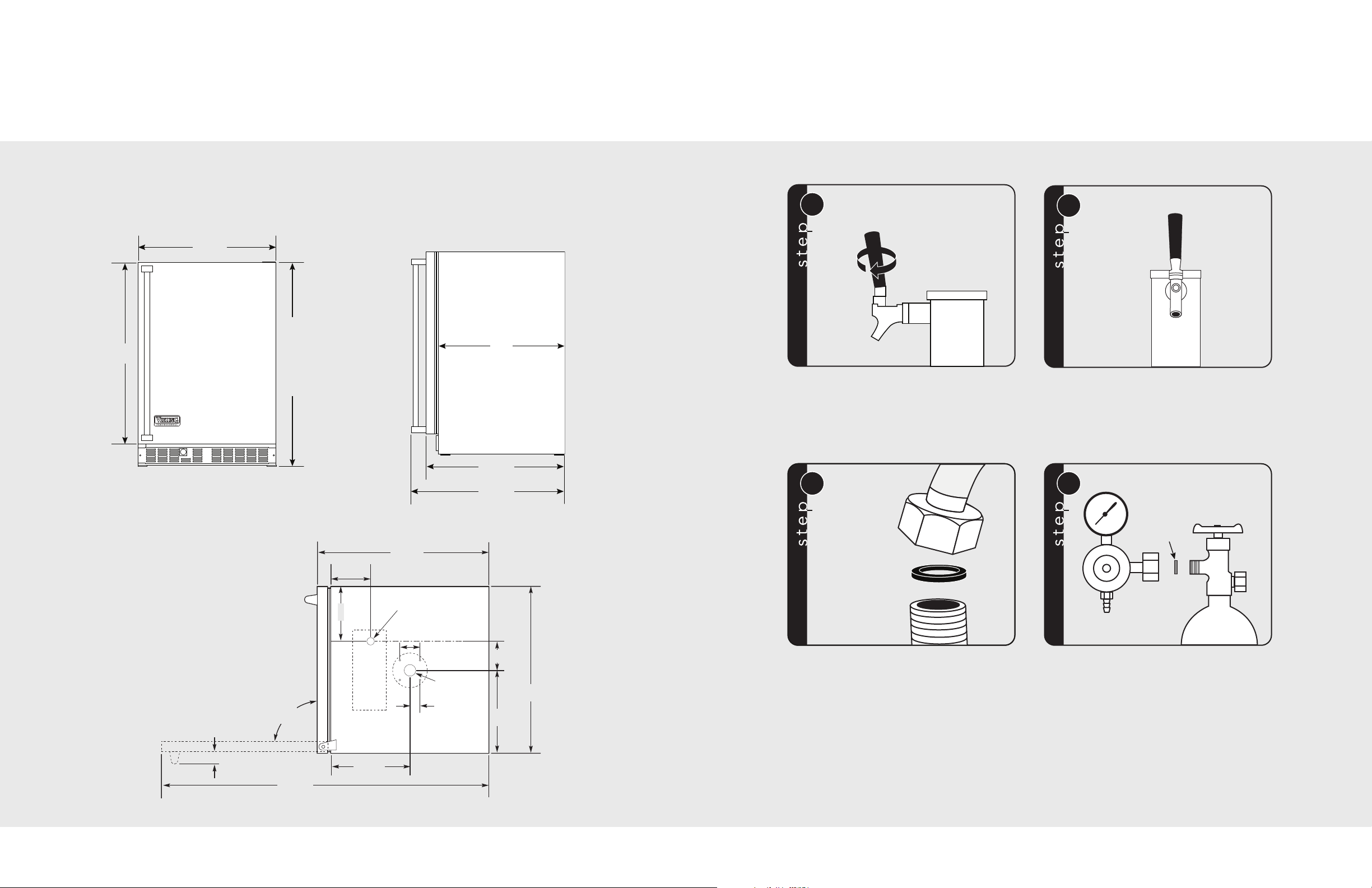
Dimensions - Undercounter Models VUBD
2
3-7/8”
(60.7 cm)
30-3/4”
(78.1 cm)
Min. 34”
(
86.4 cm)
to
Max. 34-3/4”
(88.3 cm)
with leveling
legs fully
adjusted
22”
(55.9 cm)
24-3/8”
(61.6 cm)
26-7/8”
(68.3 cm)
24-3/8”
(61.9 cm)
90°
23-7/8”
(60.7 cm)
47-1/4”
(120.0 cm)
2-1/2”
(6.4 cm)
8”
(20.3 cm)
5”
(12.7 cm)
2-11/16”
(6.8 cm) TYP
12”
(30.5 cm)
4”
(10.2 cm)
11”
(27.9 cm)
3/4” (1.9 cm)
Diameter
1-11/32”
(3.4 cm) TYP
1-1/2” (3.8 cm)
Diameter
1
Knob
Faucet
2
Draft
Tower
3
Black
Washer
Top of Keg
Coupler
Beverage Line
Assembly
4
Regulator
CO
2
Cylinder
Gray
Fiber
Washer
Front View Side View
Beverage Dispenser Assembly
Top View
10
Screw the black faucet knob onto the faucet.
Attach the clear beverage line coming from the
draft tower to the keg coupler. Use the black
washer inside the hex nut and tighten securely
with crescent wrench.
Insert the clear beverage line from the tower
through the hole in the top of the unit. Mount
the draft tower onto the refrigerator using the (4)
furnished screws and (1) mounting gasket.
Fasten the CO2regulator to the CO2tank,
tightening the CO
fiber washer between the regulator nut and the
nut securely, using the gray
2
cylinder.
11
Page 7
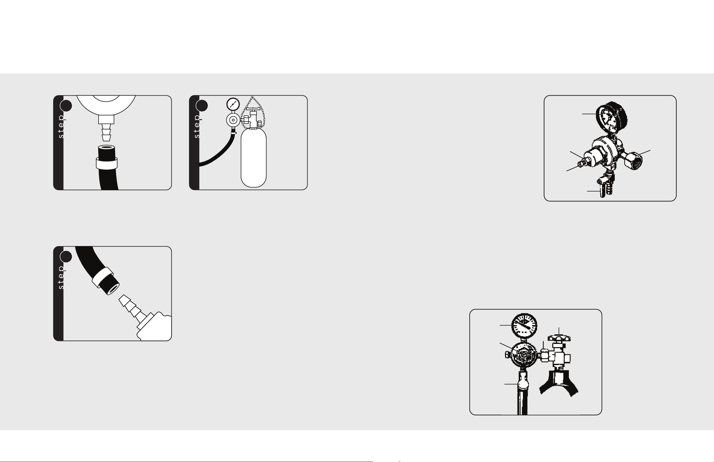
Beverage Dispenser Assembly
5
Regulator
Hose Barb
Snap Clamp
Red Air Line
6
CO
2
Cylinder
7
Snap
Clamp
Keg Coupler
Red Air Line
1
2
3
4
5
A
E
B
C
D
CO
1. Low pressure gauge (reads the amount of
internal keg pressure)
2. Adjustment lock nut
3. Regulator adjustment screw
(after keg is tapped, screw clockwise until
low pressure gauge indicates between 12
and 14 lbs.)
4. Shut-off valve
5. CO2nut (use fiber CO2washer)
Regulator
2
Attach one end of the red air line to the hose
barb on the CO
snap clamps provided. (Use pliers to snap the
clamp tight to assure that there is no gas leak.)
Fasten the other end of the red air line to the
keg coupler using the remaining snap clamp.
regulator, using one of the two
2
Place the CO
corner of the refrigerator. NOTE: It is important
that the cylinder be kept in an upright position to
operate efficiently. Secure the cylinder using the
provided chain by looping the chain around the
cylinder and regulator in the right
2
cylinder valve and regulator.
How to Replace an Empty CO2Cylinder
1. Close cylinder valve by turning clockwise “A”.
2. Unscrew adjustment screw (counter-clockwise) “B” as far as it will go.
3. Remove the regulator from empty cylinder “E”.
4. Remove dust cap from new cylinder “E”. Open and close valve “A” quickly to blow dust
from outlet.
5. With cylinder valve “A” in closed position, reattach regulator to cylinder at “E”. Be sure to
include the CO
6. Open valve “A” all the way. (This is important because this cylinder valve seals in two
places.)
7. Readjust regulator pressure “B” and open valve “C”.
washer.
2
12
13
Page 8
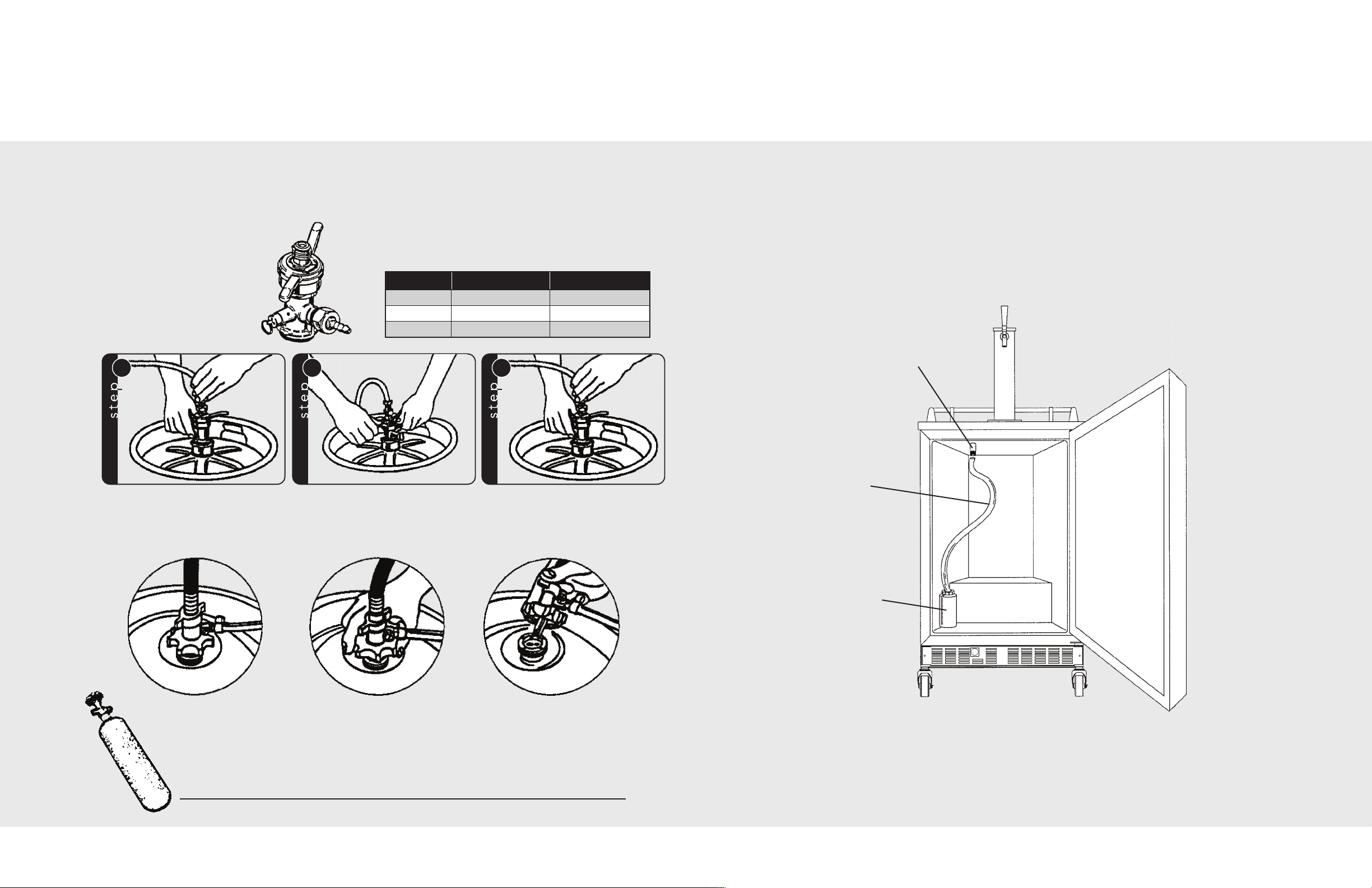
Tapping Procedures
1
2
3
Drain Hose & Container
There are two keg sizes:
1) the quarter barrel containing 7-3/4 gallons or approximately 3-1/2 cases of 12 ounce bottles
2) the half barrel containing 15-1/2 gallons or approximately 7 cases
SANKEY TYPE KEG
COUPLER
(Taps all Coors™,
Miller™ and
Budweiser™ kegs)
Align lug locks on tavern head with lug
housing in top of key. Insert tavern
head.
Turn tavern head handle 1/4 turn
clockwise. The tavern head is now
secured to keg.
APPROXIMATE MEASUREMENTS
REQUIRED TO TAP MOST KEGS
Quarter Barrel Half Barrel
Height
Diameter
Weight
17 - 21 inches 25 - 29 inches
16 - 20 inches 18 - 22 inches
80 - 85 pounds 160 - 180 pounds
Rotate on/off valve handle 1/4 turn
clockwise to open beer and CO
in keg. The keg is now tapped.
ports
2
Before using the beverage dispenser, make sure the drain hose and container are properly
installed.
1. Attach the hose to the drain.
2. Attach the container to the hose.
3. Empty the container when it becomes full.
4. Rinse both the hose and container before reattaching to the beverage dispenser.
Drain
Drain
Hose
TWIN PROBE KEG TAPS
Drain
Container
Insert probes Screw Tavern knob
hand tight
CO2Cylinders (It is recommended to have an extra cylinder on hand.)
Cylinder Diameter Height Empty Weight Full Weight
5 lbs. 5” 17-1/2” 12-1/2 lbs. 17-1/2 lbs.
14 15
Turn on pressure
and draw beer
Page 9
Final Preparation
1
2
3
4
• Some stainless steel parts may have a plastic protective wrap which must be peeled off. The
interior should be washed thoroughly with hot, soapy water to remove film residues and any
dust or debris before being used, then rinsed and wiped dry. Solutions stronger than soap
and water are rarely needed.
• All stainless steel body parts should be wiped with hot, soapy water and with a liquid cleaner
designed for this material. If buildup occurs, do not use steel wool, abrasive cloths, cleansers,
or powders! Do not use a metal knife, spatula, or any other material tool to scrape stainless
steel! Scratches are almost impossible to remove.
General Tips & Suggestions
• After making a temperature change, allow 24 hours for your unit to reach a new temperature
setting.
• The motor will stop and start often. It must do this to maintain the temperature you select.
• Unplug the appliance before working on anything with the electrical system.
• Exercise caution when sweeping, vaccuming or mopping near the front of the unit. Damage
to the grill can occur.
• For all cleaning, mix 2 tablespoons baking soda with 1 quart warm water or use mild, soapy,
water solution. Do not use strong cleaners or scouring powder or pads.
• Keep your appliance out of direct sunlight.
• Do not splash or spray water on or under the unit.
• Clean your appliance’s condenser periodically to maintain proper cooling performance.
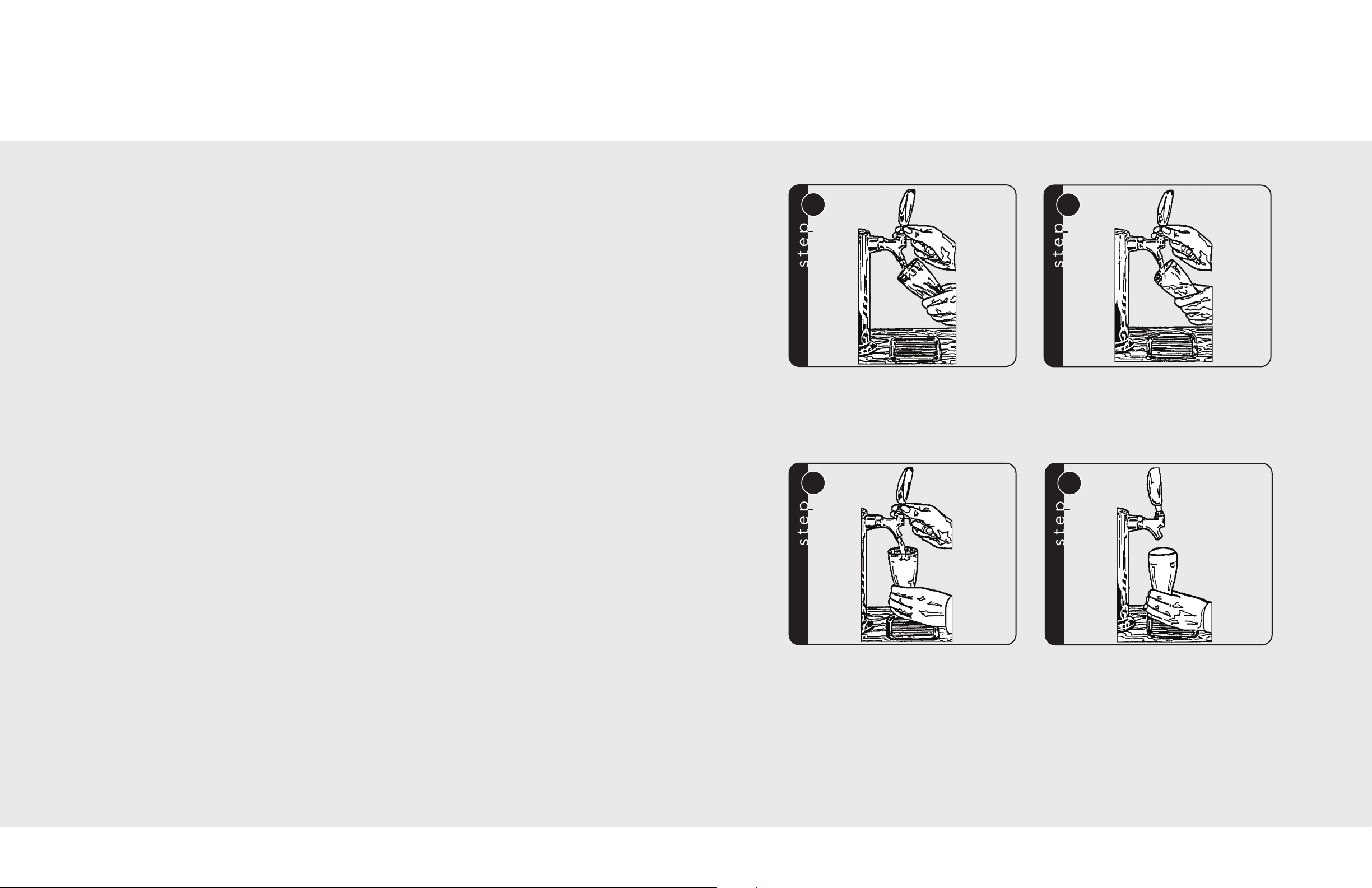
Drawing the Perfect Glass of Beer
Start with a clean beer glass that has been
wetted in cold water. Place the glass at a 45°
angle, one inch below the faucet. DO NOT let
the glass touch the faucet. Open the faucet all
the way.
After the glass has reached half full, gradually
bring the glass to an upright position.
Operating Instructions
SETTING THE CONTROL
NOTE: The control is factory set for the ideal draft beer temperature - 38°F (3.3°C).
(Temperature setting may need adjustments depending on ambient temperature.)
Initially set the cold control knob midway between the numbers. Allow at least 48 hours for the
unit to stabilize before making any adjustments to the initial temperature setting. The higher the
number, the cooler the temperature.
The temperature control knob is located at the bottom front of the cabinet, just behind the
square opening near the middle of the grill.
Draft beer is not pasteurized, so it must be kept cold - preferably around 38°F (3.3°C).
Temperatures above 45°F (7.2°C) may cause the beer to become wild, turn sour and cloudy.
Draft beer should be consumed within 30 days, as it is not pasteurized and loses its original
brewery fresh taste and aroma the older it gets.
16
Let the remaining beer run straight down the
middle. This insures proper release of
producing a 3/4” to 1” foam head.
CO
2
Close the faucet completely and quickly.
by
17
Page 10
Cleaning & Maintenance
Troubleshooting
Condenser
The condenser underneath the cabinet does not require frequent cleaning; however, satisfactory
cooling depends on adequate ventilation over this heat exchanger. It is recommended to annually
clean the condenser by vacuuming and brushing. To access the condenser, the unit must be
pulled out from the installation and the lower machine compartment access cover removed.
WARNING
Disconnect the power cord before removing the access cover.
Be sure that nothing obstructs the required air flow openings in front of the cabinet. At least once
or twice a year, brush or vacuum lint and dirt from the front grille area.
Cabinet
The painted cabinet can be washed with mild soap and water and thoroughly rinsed with clear
water. NEVER use abrasive scouring powders.
Interior and Door Gaskets
Wash interior compartment with mild soap and water. Mix 2 tablespoons baking soda with 1 quart
warm water. Do not use an abrasive powder, solvent, polish cleaner or undiluted detergent.
ENERGY SAVING TIPS
The following suggestions will minimize the cost of operating your refrigeration appliance.
1. Do not install your appliance next to a hot appliance, (cooker, dishwasher, etc.), heating air
duct or other heat sources.
2. Install product out of direct sunlight.
3. Assure the toe grille vents at front of unit beneath door are not obstructed. Keep toe grille
vents clean to allow ventilation for the refrigeration system to expel heat.
4. Plug your appliance into a dedicated power circuit. (Not shared with other appliances.)
5. When initially loading your new product, or whenever large quantities of warm contents are
placed within refrigerated storage compartment, minimize door openings for the next 12
hours to allow contents to pull down to compartment set-point temperature.
6. Maintaining a relatively full storage compartment will require less appliance run-time than an
empty compartment.
7. Assure door closing is not obstructed by contents stored in your appliance.
8. Allow hot items to reach room temperature before placing in product.
9. Minimize door openings and duration of door openings.
10. Use the warmest temperature control set-point that meets your personal preference and
provides the proper storage for your stored contents.
11. Minimize use of display lighting option on glass door products, (light stays on with door
closed).
12. When on vacation or away from home for extended periods, set the appliance to warmest
acceptable temperature for the stored contents.
13. Set the control to the “OFF” position if cleaning the unit requires the door to be open for an
extended period of time.
14. Annually clean condenser heat exchange coil located in machine compartment underneath
unit, (see Cleaning and Maintenance section).
PROBLEM
WILD BEER
Beer, when drawn, is all foam or too
much foam and not enough liquid
beer.
CLOUDY BEER
When beer in glass appears hazy,
not clear
FLAT BEER
Foamy head disappears quickly;
beer lacks usual, zestful, breweryfresh flavor
FALSE HEAD
Large soap-like bubbles, head
dissolves very quickly
UNPALATABLE BEER
Off-taste
POSSIBLE CAUSE AND/OR REMEDY
Beer drawn improperly
Creeping regulator
Applied pressure is set too high
Hot spots in line
Use of non-insulated beer line
Beer runs are too long for proper cooling
Tapped into a warm keg
Cooler malfunctioning
Kinks, dents, twists or other obstructions in line
Faucets in bad, dirty or worn condition
Frozen or nearly frozen beer
Old beer
Beer that has been unrefrigerated for long periods of time
Dirty glass
Dirty faucet
Unrefrigerated foods placed on top of cold keg
Contaminated air source
Dirty glasses
Sluggish regulator
Applied pressure is set too low
CO2is turned off at night
Contaminated air source (associated with compressed air)
Moisture in air system
Beer too cold
Loose tap or vent connections
Applied pressure required does not correspond to beer
temperature
Small beer line into a large faucet shank
Beer lines warmer than beer in keg
Dry glasses
Improper pour
Dirty or old beer lines
Dirty faucet
Contaminated air source or unfiltered
Unsanitary bar conditions
1918
Page 11
Service Information
Warranty
If service is required, call your dealer or authorized service agency. The name of the authorized
service agency can be obtained from the dealer or distributor in your area.
Have the following information readily available.
• Model number
• Serial number
• Date purchased
• Name of dealer from whom purchased
Clearly describe the problem that you are having. If you are unable to obtain the name of an
authorized service agency, or if you continue to have service problems, contact Viking Range
Corporation at 1-888-VIKING1 (845-4641), or write to:
VIKING RANGE CORPORATION
PREFERRED SERVICE
1803 Hwy 82W
Greenwood, Mississippi 38930 USA
Record the information indicated below. You will need it if service is ever required. The serial
number and model numbers for your beverage dispenser are located on the front of the unit at
the base of the door frame.
Model Number Serial Number
Date of Purchase Date Installed
Dealer’s Name
Address
Built-in/portable beverage dispensers and all of their components and accessories, except as detailed below*
warranted to be free from defects in material or workmanship under normal household use for a period of one (1) year from
the date of original retail purchase. Viking Range Corporation, warrantor, agrees to repair or replace, at its option, any part
which fails or is found to be defective during the warranty period.
*Painted and decorative items are warranted to be free from defective materials or workmanship for a period of ninety (90)
days from the date of original retail purchase. ANY DEFECTS MUST BE REPORTED TO THE SELLING DEALER WITHIN
NINETY (90) DAYS FROM DATE OF ORIGINAL RETAIL PURCHASE.
Any sealed refrigeration system component, as listed below, is warranted to be free from defective materials or
workmanship in normal household use during the second through the fifth year from the date of original retail purchase.
Viking Range Corporation, warrantor, agrees to repair or replace, at its option, any part which fails or is found to be
defective during the warranty period.
SSeeaalleedd RReeffrriiggeerraattiioonn SSyysstteemm CCoommppoonneennttss::
It is recommended that in temperatures above 100°F (37.8°C) and below 40°F (4.4°C) the unit be shut off. The normal
operating range for the unit is between 60°F (15.6°F) and 100°F (37.8°C).
NINETY (90) DAY RESIDENTIAL PLUS WARRANTY
This warranty applies to applications where use of the product extends beyond normal residential use. Examples are, but not
limited to, bed and breakfasts, fire stations, private clubs, churches, etc. This warranty excludes all commercial locations such
as restaurants, food service locations and institutional food service locations.
This warranty extends to the original purchaser of the product warranted hereunder and to each transferee owner of the
product during the term of the warranty.
This warranty shall apply to products purchased and located in the United States and Canada. Products must be purchased
in the country where service is requested. Warranty labor shall be performed by an authorized Viking Range Corporation
service agency or representative. Warranty shall not apply to damage resulting from abuse, accident, natural disaster, loss of
electrical power to the product for any reason, alteration, improper installation, improper operation or repair or service to
the product by anyone other than an authorized Viking Range Corporation service agency or representative. Warranty shall
not apply to damage resulting from indoor units being used in outdoor situations. This warranty does not apply to
commercial usage. Warrantor is not responsible for consequential or incidental damage whether arising out of breach of
warranty, breach of contract, or otherwise. Some jurisdictions do not allow the exclusion or limitation of incidental or
consequential damages, so the above limitation or exclusion may not apply to you.
Owner shall be responsible for proper installation, providing normal care and maintenance, providing proof of purchase
upon request, and making the appliance reasonably accessible for service. If the product or one of its component parts
contains a defect or malfunction during the warranty period, after a reasonable number of attempts by the warrantor to
remedy the defects or malfunctions, the owner is entitled to either a refund or replacement of the product or its component
part or parts. Replacement of a component part includes its free installation. Warrantor’s liability on any claim of any kind,
with respect to the goods or services covered hereunder, shall in no case exceed the price of the goods or service or part
there of which gives rise to the claim.
ONE YEAR FULL WARRANTY
FIVE YEAR LIMITED WARRANTY
Compressor, Evaporator, Condenser, Connecting Tubing, Dryer/Strainer
, are
If service requires installation of parts, use only authorized parts to insure protection under the
warranty.
KEEP THIS MANUAL FOR FUTURE REFERENCE.
20
WARRANTY SERVICE: Under the terms of this warranty, service must be performed by a factory authorized Viking Range
Corporation service agent or representative. Service will be provided during normal business hours, and labor performed at
overtime or premium rates shall not be covered by this warranty. To obtain warranty service, contact the dealer from whom the
product was purchased, an authorized Viking Range Corporation service agent, or Viking Range Corporation. Provide model and
serial number and date of original purchase. For the name of your nearest authorized Viking Range Corporation service agency,
call the dealer from whom the product was purchased or Viking Range Corporation. IMPORTANT: Retain proof of original
purchase to establish warranty period.
The return of the Owner Registration Card is not a condition of warranty coverage. You, however, should return the Owner
Registration Card so that Viking Range Corporation can contact you should any question of safety arise which could affect
you.
Any implied warranties of merchantability and fitness applicable to the above described undercounter refrigerator are
limited in duration to the period of coverage of the applicable express written limited warranties set forth above. Some
jurisdictions do not allow limitations on how long an implied warranty lasts, so the above limitation may not apply to you.
This warranty gives you specific rights, and you may also have other rights which may vary from jurisdiction to jurisdiction.
Specifications subject to change without notice.
21
Page 12
2322
 Loading...