

Viking Vmor-dmor205 Owner's Manual
SERVICE MANUAL
VMOR205SS
DMOR205SS
S95M255VMO205
DMOR205SS
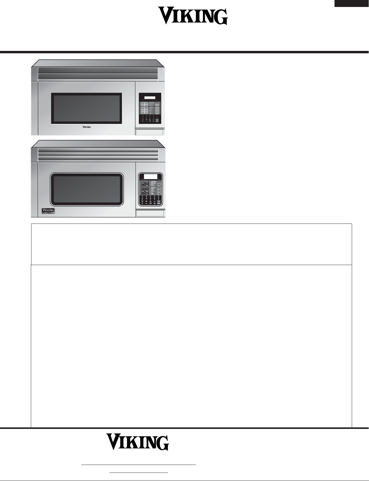
OVER THE RANGE
MICROWAVE OVEN
MODELS DMOR205SS
VMOR205SS
VMOR205SS
In the interest of user-safety, the oven should be restored to its original condition and only parts identical to those specified
should be used.
WARNING TO SERVICE PERSONNEL: Microwave ovens contain circuitry capable of producing very high voltage and
current, contact with following parts may result in a severe, possibly fatal, electrical shock. (High Voltage Capacitor, High
Voltage Power Transformer, Magnetron, High Voltage Rectifier Assembly, High Voltage Harness etc..)
TABLE OF CONTENTS
Page
PRECAUTIONS TO BE OBSERVED BEFORE AND DURING SERVICING TO
AVOID POSSIBLE EXPOSURE TO EXCESSIVE MICROWAVE ENERGY ................... INSIDE FRONT COVER
BEFORE SERVICING ...................................................................................................... INSIDE FRONT COVER
MICROWAVE MEASUREMENT PROCEDURE ..................................................................................................... 2
WARNING TO SERVICE PERSONNEL ................................................................................................................4
FOREWORD AND WARNING ................................................................................................................................5
PRODUCT SPECIFICATIONS ............................................................................................................................... 6
GENERAL INFORMATION ...................................................................................................................................6
OPERATION .........................................................................................................................................................9
TROUBLESHOOTING GUIDE ... ......... .................................................................................................................17
TEST PROCEDURE ............................................................................................................................................20
TOUCH CONTROL PANEL ASSEMBLY .............................................................................................................31
COMPONENT REPLACEMENT AND ADJUSTMENT PROCEDURE .................................................................. 37
PICTORIAL DIAGRAM ........................................................................................................................................ 46
LSI UNIT CIRCUIT ...............................................................................................................................................47
PRINTED WIRING BOARD ................................................................................................................................. 48
PARTS LIST ........................................................................................................................................................ 49
PACKING AND ACCESSORIES ......................................................................................................................... 54
This document has been published
Range Corporation
111 Front St., Greenwood, MS 38930
to be used for after sales service only.
The contents are subject to change
without notice
.
Tel: (888) 845-4641

VMOR205SS
DMOR205SS
PRECAUTIONS TO BE OBSERVED BEFORE AND
DURING SERVICING TO AVOID POSSIBLE
EXPOSURE TO EXCESSIVE MICROWAVE ENERGY
(a) Do not operate or allow the oven to be operated with the door open.
(b) Make the following safety checks on all ovens to be serviced before activating the magnetron or other microwave
source, and make repairs as necessary: (1) interlock operation, (2) proper door closing, (3) seal and sealing surfaces
(arcing, wear, and other damage), (4) damage to or loosening of hinges and latches, (5) evidence of dropping or
abuse.
(c) Before turning on microwave power for any service test or inspection within the microwave generating compartments,
check the magnetron, wave guide or transmission line, and cavity for proper alignment, integrity, and connections.
(d) Any defective or misadjusted components in the interlock, monitor, door seal, and microwave generation and
transmission systems shall be repaired, replaced, or adjusted by procedures described in this manual before the
oven is released to the owner.
(e) A microwave leakage check to verify compliance with the Federal Performance Standard should be performed on
each oven prior to release to the owner.
BEFORE SERVICING
Before servicing an operative unit, perform a microwave emission check as per the Microwave Measurement Procedure outlined in this service manual.
If microwave emissions level is in excess of the specified limit, contact Viking Service immediately @
1-888-845-4641.
If the unit operates with the door open, service person should (1) tell the user not to operate the oven and
(2) contact VIKING, plus the Department Of Health, Canada and/or the Food and Drug Administration's
Center for Devices and Radiological Health immediately.
Service personnel should inform VIKING of any certified unit found with emissions in excess of 4mW/cm2.
The owner of the unit should be instructed not to use the unit until the oven has been brought into compliance.
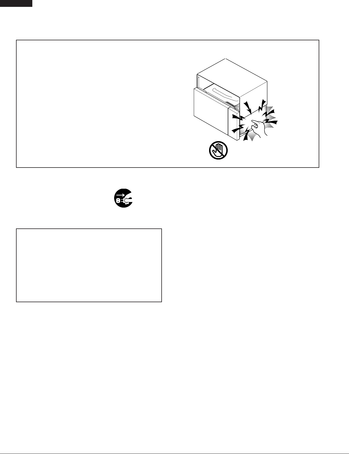
DANGER CAUTION
HIGH VOLTAGE
Do not energize a microwave oven with the outer case cabinet removed, because a microwave oven
generates High Voltage in the circuit.
If you intend to operate the oven employing the high frequency switching power converter circuit, you should
take special precautions to avoid an electrical shock hazard.
The high voltage transformer, high voltage capacitor and high voltage diode have energized high voltage
potential approx. 8 KV.
The aluminium heat sink is connected to the switching power transistor Collector pole, and has an energized
high voltage potential approx. 650V peak.
DO NOT ACCESS THE HIGH VOLTAGE TRANSFORMER, HIGH VOLTAGE CAPACITOR, HIGH
VOLTAGE DIODE AND HEAT SINK WHEN THE POWER SUPPLY IS CONNECTED TO AN
ELECTRICAL OUTLET.

Notes
VMOR205SS
DMOR205SS
1

VMOR205SS
DMOR205SS
MICROWAVE MEASUREMENT PROCEDURE (USA)
A. Requirements:
1) Microwave leakage limit (Power density limit): The power density of microwave radiation emitted by a microwave oven
should not exceed 1mW/cm2 at any point 5cm or more from the external surface of the oven, measured prior to acquisition
by a purchaser, and thereafter (through the useful life of the oven), 5 mW/cm
surface of the oven.
2) Safety interlock switches Primary interlock relay and door sensing switch shall prevent microwave radiation emission
in excess of the requirement as above mentioned, secondary interlock switch shall prevent microwave radiation
emission in excess of 5 mW/cm2 at any point 5cm or more from the external surface of the oven.
B. Preparation for testing:
Before beginning the actual measurement of leakage, proceed as follows:
1) Make sure that the actual instrument is operating normally as specified in its instruction booklet.
Important:
Survey instruments that comply with the requirement for instrumentation as prescribed by the performance standard
for microwave ovens, 21 CFR 1030.10(c)(3)(i), must be used for testing.
2) Place the oven tray in the oven cavity.
3) Place the load of 275±15 ml (9.8 oz) of tap water initially at 20±5½C (68½F) in the center of the oven cavity.
The water container shall be a low form of 600 ml (20 oz) beaker with an inside diameter of approx. 8.5 cm (3-1/2
in.) and made of an electrically nonconductive material such as glass or plastic.
The placing of this standard load in the oven is important not only to protect the oven, but also to insure that any leakage
is measured accurately.
4) Set the cooking control on Full Power Cooking Mode
5) Close the door and select a cook cycle of several minutes. If the water begins to boil before the survey is completed,
replace it with 275 ml of cool water.
2
at any point 5cm or more from the external
C. Leakage test:
Closed-door leakage test (microwave measurement)
1) Grasp the probe of the survey instrument and hold it perpendicular to the gap between the door and the body of the oven.
2) Move the probe slowly, not faster than 1 in./sec. (2.5 cm/sec.) along the gap, watching for the maximum indication on
the meter.
3) Check for leakage at the door screen, sheet metal seams and other accessible positions where the continuity of the
metal has been breached (eg., around the switches, indicator, and vents).
While testing for leakage around the door pull the door away from the front of the oven as far as is permitted by the closed
latch assembly.
4) Measure carefully at the point of highest leakage and make sure that the highest leakage is no greater than 4mW/cm2,
and that the secondary interlock switch does turn the oven OFF before any door movement.
NOTE: After servicing, record data on service invoice and microwave leakage report.
2

VMOR205SS
DMOR205SS
MICROWAVE MEASUREMENT PROCEDURE (CANADA)
After adjustment of the door switches are completed individually or collectively, switch test and microwave leakage test must
be performed with survey instrument and test result must be confirmed to meet the requirement of the performance standard
for microwave ovens as undermentioned.
A. Requirements:
Every microwave oven shall function in such a manner that when the oven is fully assembled and operating with it's service
controls and user controls adjusted to yield the maximum output, the leakage radiation, at all points at least 5 cm. from the
external surface of the oven, does not exceed:
1) 1.0mW/cm2 with the test load of 275 ± 15 ml of water at an initial temperature 20 ±5oC.
2) 5.0mW/cm
3) 5.0mW/cm
2
when the outer enclosure is removed with a test load of 275 ± 15 ml of water at an initial temperature 20±5oC.
2
without a test load.
B. Preparation for testing:
Before beginning the actual measurement of leakage, proceed as follows:
1) Make sure that the actual instrument is operating normally as specified in its instruction booklet.
Important:
Survey instruments that comply with the requirement for instrumentation as prescribed by CSA and NHW performance standard
for microwave ovens must be used for testing recommended instruments are , NARDA 8100 and NARDA 8200.
2) Place the oven tray in the oven cavity.
3) Place the load of 275±15 ml of tap water initially at 20±5oC in the center of the oven cavity.
The water container shall be a low form of 600 ml beaker with an inside diameter of approx. 8.5 cm (3-1/2 in.) and made
of an electrically nonconductive material such as glass or plastic.
The placing of this standard load in the oven is important not only to protect the oven, but also to insure that any leakage
is measured accurately.
4) Set the cooking control on Full Power Cooking Mode, Close the door and select a cook cycle of several minutes. If the water
begins to boil before the survey is completed, replace it with 275 ml of cool water.
C. Leakage test with enclosure installed :
1) Grasp the probe of the survey instrument and hold it perpendicular to the gap between the door and the body of the oven.
2) Move the probe slowly, not faster than 2.5 cm/sec. along the gap, watching for the maximum indication on the meter.
3) Check for leakage at the door screen, sheet metal seams and other accessible positions where the continuity of the metal
has been breached (eg., around the switches, indicator, and vents).
While testing for leakage around the door pull the door away from the front of the oven as far as is permitted by the closed
latch assembly.
4) Measure carefully at the point of highest leakage and make sure that the highest leakage is no greater than 4mW/cm2, and
that the secondary interlock switch does turn the oven OFF before any door movement.
C. Leakage test without enclosure:
1) Remove the enclosure (cabinet).
2) Grasp the probe of the survey instrument and hold it perpendicular to all mechanical and electric parts of the oven that is
accessible to the user of the oven including, but not limited to, the waveguide, cavity seams, magnetron gap between the
door and the body of the oven.
3) Move the probe slowly, not faster than 2.5 cm/sec. along the gap, watching for the maximum indication on the meter.
4) Measure carefully at the point of highest leakage and make sure that the highest leakage is under 5mW/cm2.
CAUTION: Special attention should be given to avoid electrical shock because HIGH VOLTAGE is generated during this test
No Load test
1) Operate the oven without a load and measure the leakage by the same method as the above test procedure " Leakage
test with enclosure installed"
2. Make sure that the highest leakage should not exceed 5mW/cm2.
NOTE: After servicing, record data on service invoice and microwave leakage report.
3
VMOR205SS
e
DMOR205SS
WARNING TO SERVICE PERSONNEL
Microwave ovens contain circuitry capable of producing very high voltage and current, contact with
following parts
fatal, electrical shock.
(Example)
High Voltage Capacitor, High Voltage Power Trans-
former, Magnetron, High Voltage Rectifier Assembly, High Voltage Harness etc..
Read the Service Manual carefully and follow all
instructions.
may result in a severe, possibly
Don't Touch !
Danger High Voltag
Before Servicing
1. Disconnect the power supply cord , and then
remove outer case.
2. Open the door and block it open.
3. Discharge high voltage capacitor.
WARNING: RISK OF ELECTRIC SHOCK.
DISCHARGE THE HIGH-VOLTAGE
CAPACITOR BEFORE
SERVICING.
The high-voltage capacitor remains charged about 60
seconds after the oven has been switched off. Wait for 60
seconds and then short-circuit the connection of the highvoltage capacitor (that is the connecting lead of the highvoltage rectifier) against the chassis with the use of an
insulated screwdriver.
Whenever troubleshooting is performed the power supply
must be disconnected. It may in, some cases, be necessary
to connect the power supply after the outer case has been
removed, in this event,
1. Disconnect the power supply cord, and then remove outer
case.
2. Open the door and block it open.
3. Discharge high voltage capacitor.
4. Disconnect the leads to the primary of the power
transformer.
5. Ensure that these leads remain isolated from other
components and oven chassis by using insulation tape.
6. After that procedure, reconnect the power supply cord.
When the testing is completed,
1. Disconnect the power supply cord, and then remove outer
case.
2. Open the door and block it open.
3. Discharge high voltage capacitor.
4. Reconnect the leads to the primary of the power
transformer.
5. Reinstall the outer case (cabinet).
6. Reconnect the power supply cord after the outer case is
installed.
7. Run the oven and check all functions.
After repairing
1. Reconnect all leads removed from components during
testing.
2. Reinstall the outer case (cabinet).
3. Reconnect the power supply cord after the outer case is
installed.
4. Run the oven and check all functions.
Microwave ovens should not be run empty. To test for the
presence of microwave energy within a cavity, place a cup of
cold water on the oven turntable, close the door and set the
power to HIGH and set the microwave timer for two (2)
minutes. When the two minutes has elapsed (timer at zero)
carefully check that the water is now hot. If the water remains
cold carry out Before Servicing procedure and re-examine
the connections to the component being tested.
When all service work is completed and the oven is fully
assembled, the microwave power output should be checked
and microwave leakage test should be carried out.
4

SERVICE MANUAL
VIKING RANGE CORPORATION
MICROWAVE OVENS
PRODUCT DESCRIPTION
VMOR205SS
DMOR205SS
VMOR205SS
DMOR205SS
FOREWORD
This Manual has been prepared to provide Viking Service Personnel with
Operation and Service Information for the VIKING MICROWAVE OVENS,
VMOR205SS and DMOR205SS.
It is recommended that service personnel carefully study the entire text
of this manual and the base model's manual so that they will be qualified
to render satisfactory customer service.
Check the interlock switches and the door seal carefully. Special
attention should be given to avoid electrical shock and microwave
radiation hazard.
WARNING
Never operate the oven until the following points are ensured:
(A) The door is tightly closed.
(B) The door brackets and hinges are not defective.
(C) The door packing is not damaged.
(D) The door is not deformed or warped.
(E) There is no other visible damage with the oven.
Servicing and repair work must be carried out only by trained service
personnel.
DANGER
Certain initial parts are intentionally not grounded and present
a risk of electrical shock only during servicing. Service personnel - Do not contact the following parts while the appliance is
energized;
High Voltage Capacitor, Power Transformer, Magnetron, High
Voltage Rectifier Assembly, High Voltage Harness;
If provided, Vent Hood, Fan assembly, Cooling Fan Motor.
GENERAL INFORMATION
OPERATION
TROUBLESHOOTING GUIDE AND
TEST PROCEDURE
TOUCH CONTROL PANEL
COMPONENT REPLACEMENT
AND ADJUSTMENT PROCEDURE
WIRING DIAGRAM
PARTS LIST
All the parts marked “*” on parts list are used at voltages more than
250V.
Removal of the outer wrap gives access to voltage above 250V.
VIKING RANGE CORPORATION
111 Front St., Greenwood, MS 38930
Tel: (888) 845-4641
5
VMOR205SS
DMOR205SS
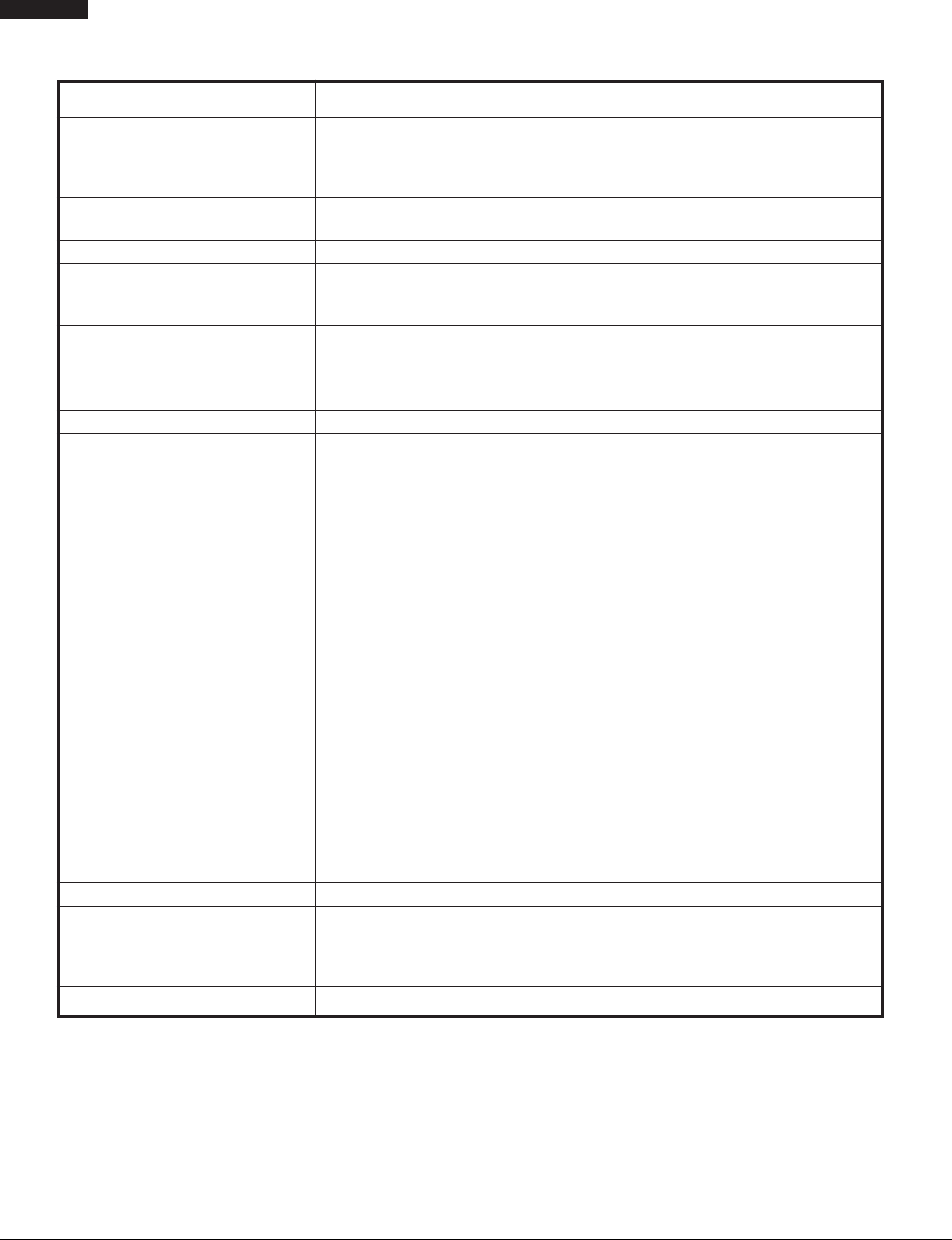
SPECIFICATION
ITEM DESCRIPTION
Power Requirements
Power Output 850 watts (IEC-705 TEST PROCEDURE)
Convection Power Output 1400 watts
Case Dimensions Width 29-15/16"
Cooking Cavity Dimensions Width 17-1/8"
1.1 Cubic Feet Depth 13-13/16"
Hood lamps (2) 1 bulb @ 20W & 1 bulb @ 40W
Hood fan Horizontal discharge 230 C.F.M. , Vertical discharge 240 C.F.M. ,
Control Complement Touch Control System
120 Volts / 13.2 Amperes (Microwave), 13.2 Amperes (Convection) - [UL Rating]
116 Volts / 13.2 Amperes (Microwave), 13.2 Amperes (Convection) - [CSA Rating]
60 Hertz
Single phase, 3 wire grounded
Operating frequency of 2450MHz
Height 16-11/32"
Depth 15- 9/32"
Height 8-1/16"
Clock ( 1:00 - 12:59 )
Timer (0 - 99 min. 99 seconds)
Microwave Power for Variable Cooking
Repetition Rate;
P-HI .................................................. Full power throughout the cooking time
P-90 .................................................................... approx. 90% of Full Power
P-80 .................................................................... approx. 80% of Full Power
P-70 .................................................................... approx. 70% of Full Power
P-60 .................................................................... approx. 60% of Full Power
P-50 .................................................................... approx. 50% of Full Power
P-40 ..................................................................... approx. 40% of Full Power
P-30 ..................................................................... approx. 30% of Full Power
P-20 .................................................................... approx. 20% of Full Power
P-10 ...................................................................... approx. 10% of Full Powe
P-0 ...................................................... No power throughout the cooking time
Help pad, Sensor Cook pad, Auto Broil pad, Auto Roast pad
Auto Bake pad, Sensor Reheat pad, More Time pad, Popcorn pad
Timed Defrost pad, Convect pad, Preheat pad, Combination Bake pad
Combination Roast pad, Broil pad, Slow Cook pad, Timer pad
Number and temperature selection pads, Clock pad, Hold Warm pad
Turntable On / Off pad, Power Level pad, Stop/Clear pad,
Start / Touch On pad, Fan Hi/Lo/Off, Light.
Oven Cavity Light Yes 20W x 1 Incandescent light bulb
Safety Standard UL Listed FCC Authorized
DHHS Rules, CFR, Title 21, Chapter 1, Subchapter J
Canadian Standards Association.
Health CANADA, Industry CANADA.
Weight Approx. 71 lbs.
GENERAL INFORMATION
GROUNDING INSTRUCTIONS
This oven is equipped with a three prong grounding plug. It must be plugged into a wall receptacle that is properly installed and
grounded in accordance with the National Electrical Code and local codes and ordinances.
In the event of an electrical short circuit, grounding reduces the risk of electric shock by providing an escape wire for the electric
current.
WARNING: Improper use of the grounding plug can result in a risk of electric shock.
6
VMOR205SS
DMOR205SS
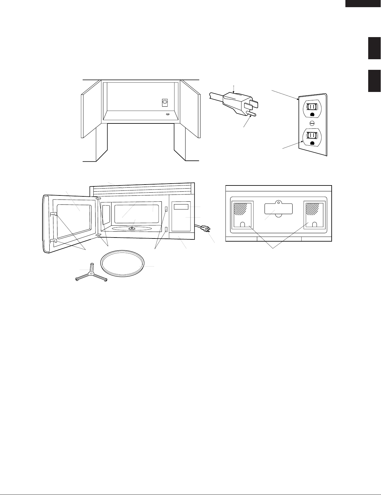
Electrical Requirements
The oven is equipped with a 3-prong grounding plug. DO NOT UNDER ANY CIRCUMSTANCES CUT OR REMOVE THE
GROUNDING PIN FROM THE PLUG.
The power supply cord and plug must be connected to a separate 120 Volt AC, 60 Hz, 15 Amp. or more branch circuit, using
a grounded receptacle. The receptacle should be located inside the cabinet directly above the Microwave Oven/Hood system
mounting location.
3-Pronged Plug
Grounding Pin
3-Pronged Receptacle
Grounded
Receptacle Box
OVEN DIAGRAM
10
1
9
5
4
3
6
2
6
8
7
15
11
12
14
13
1. Oven door with see-through window.
2. Door hinges.
3. Sirrer cover.
4. Turntable motor shaft.
5. Oven lamp.
It will light when oven is operating or door is open.
6. Door latches.
The oven will not operate unless the door is securely closed.
7. One touch door open button.
Push to open door.
8. Auto-Touch control panel.
9. Time display: Digital display, 99 minutes 99 seconds.
10. Ventilation openings.
11. Light Cover.
12. Grease filters.
13. Removable turntable.
The turntable will rotate clockwise or counterclockwise.
Only remove for cleaning.
14. Removable turntable support.
15.Plug
7
VMOR205SS
DMOR205SS
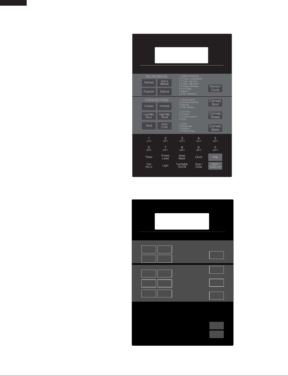
CONTROL PANEL
NOTE:
Some one-touch cooking features as
"More Time " are disabled after one
minute when the oven is not used.
These features are automatically enabled when the door is opened and
closed or the STOP/ CLEAR pad s are
pressed.
MICROWAVE
Rehe at
Pop co rn Defrost
CONVECTION
Convec Prehea t
Low Mix
Ba ke
Tim e r
Hi/Lo
VMOR205SS Key Sheet
1 Bak ed po tatoe s
2 Frozen vegetables
3 Fresh veg -soft
4 Fresh veg -hard
5 Frozen entrees
6 Hot dogs
7 Bac on
8 Fish, sea food
1 Ham burge rs
2 Chicken pieces
3 Stea ks
4 Fish ste ak s
1 C hicke n
2 Turkey
3 Turk ey bre ast
4 Pork
1 C ak e
2 Brownies
3 Muffins
4 Frenc h fries
3
275ûF
8
400ûF
Keep
Wa rm
Tu rn ta b l e
On/Off
Broil
1
100ûF
6
350ûF
Fa n
Add-A
Minute
High M ix
Roa st
Slow
Cook
2
150ûF
7
375ûF
Powe r
Le ve l
Lig ht
4
300ûF
9
425ûF
Clock
Stop /
Clear
Sensor
Cook
Convec
Broil
Convec
Roa st
Convec
Ba ke
5
325ûF
0
450ûF
Help
Start /
To uc h O n
DMOR205SS Key Sheet
8

OPERATION
DESCRIPTION OF OPERATING SEQUENCE
VMOR205SS
DMOR205SS
The following is a description of component functions during
oven operation.
OFF CONDITION
Closing the door activates the door sensing switch and
secondary interlock switch. (In this condition, the monitor
switch contacts are opened.)
When oven is plugged in, 120 volts A.C. is supplied to the
control unit. (Figure O-1).
1. The display will show "Welcome".
To set any program or set the clock, you must first touch
the STOP/CLEAR pad. The display will clear, and " : "
will appear.
COOKING CONDITION
Program desired cooking time touching the NUMBER pads.
When the START pad is touched, the following operations
occur:
1. The contacts of relays are closed and components
connected to the relays are turned on as follows.
(For details, refer to Figure O-2)
RELAY CONNECTED COMPONENTS
RY1 Oven lamp
RY2 Power transformer/ Stirrer motor
RY4 Turntable motor
RY5 Fan motor
2. 120 volts A.C. is supplied to the primary winding of the
power transformer and is converted to about 3.3 volts
A.C. output on the filament winding, and approximately
2000 volts A.C. on the high voltage winding.
3. The filament winding voltage heats the magnetron filament
and the H.V. winding voltage is sent to a voltage doubler
circuit.
4. The microwave energy produced by the magnetron is
channelled through the waveguide into the cavity feedbox, and then into the cavity where the food is placed to
be cooked.
5. Upon completion of the cooking time, the power
transformer, oven lamp, etc. are turned off, and the
generation of microwave energy is stopped. The oven
will revert to the OFF condition.
6. When the door is opened during a cook cycle, monitor
switch, door sensing switch, secondary switch and third
door switch and primary interlock relay are activated with
the following results. The circuits to the stirrer motor, the
cooling fan motor, the turntable motor, and the high
voltage components are de-energized, and the digital
read-out displays the time still remaining in the cook cycle
when the door was opened.
7. The monitor switch is electrically monitoring the operation
of the secondary and third door door switch and primary
interlock relay and is mechanically associated with the
door so that it will function in the following sequence.
(1) When the door opens from a closed position, the
primary interlock relay, door sensing switch,
secondary and third door switch open their contacts,
and then the monitor switch contacts close.
(2) When the door is closed from the open position, the
monitor switch contacts first open, and then the
contacts of the secondary and third door switch close.
If the primaryswitch, secondary switch and secondary interlock relay fail with their contacts closed when the door is
opened, the closing of the monitor switch contacts will form
a short circuit through the monitor fuse, secondary switch
,third door switch and primary interlock relay, causing the
monitor fuse to blow.
POWER LEVEL P-0 TO P-90 COOKING
When Variable Cooking Power is programmed, the 120 volts
A.C. is supplied to the power transformer intermittently
through the contacts of relay (RY2) which is operated by the
control unit within an interval second time base. Microwave
power operation is as follows:
VARI-MODE ON TIME OFF TIME
Power 10(P-HI) 32 sec. 0 sec.
(100% power)
Power 9(P-90) 30 sec. 2 sec.
(approx. 90% power)
Power 8(P-80) 26 sec. 6 sec.
(approx. 80% power)
Power 7(P-70) 24 sec. 8 sec.
(approx. 70% power)
Power 6(P-60) 22 sec. 10 sec.
(approx. 60% power)
Power 5(P-50) 18 sec. 14 sec.
(approx. 50% power)
Power 4(P-40) 16 sec. 16 sec.
(approx. 40% power)
Power 3(P-30) 12 sec. 20 sec.
(approx. 30% power)
Power 2(P-20) 8 sec. 24 sec.
(approx. 20% power)
Power 1(P-10) 6 sec. 26 sec.
(approx. 10% power)
Power 0(P-0) 0 sec. 32 sec.
(0% power)
Note: The ON/OFF time ratio does not correspond with the
percentage of microwave power, because approx.
2 seconds are needed for heating of the magnetron
filament.
CONVECTION COOKING CONDITION
PREHEATING CONDITION
Program desired convection temperature by touching the
PREHEAT pad and the temperature pad.
When the START pad is touched, the following operations
occur:
9

VMOR205SS
DMOR205SS
1. The coil of shut-off relays (RY1, RY4, RY5 and RY7) are
energized, the oven lamp, turntable motor, cooling fan
motor and convection motor are turned on.
2. The coil of relay (RY6) is energized by the control unit.
The damper is moved to the closed position, opening the
damper switch contacts. The opening of the damper
switch contacts sends a signal to the LSI on the control
unit de-energizing the relay (RY6) and opening the
circuit to the damper motor.
3. The coil of heater relay (RY3) is energized by the control
unit and the main supply voltage is applied to the heating
element.
4. When the oven temperature reaches the selected preheat
temperature, the following operations occur:
4-1 The heater relay is de-energized by the control unit
temperature circuit and thermistor, opening the
circuit to the heating element.
4-2. The oven will continue to function for 30 minutes,
turning the heater on and off, as needed to maintain
the selected preheat temperature. The oven will
shutdown completely after 30 minutes
CONVECTION COOKING CONDITION
When the preheat temperature is reached, a beep signal will
sound indicating that the holding temperature has been
reached in the oven cavity. Open the door and place the food
to be cooked in the oven.
Program convection temperature and desired cooking time
by touching the CONVECT pad, Temperature pad and
NUMBER pad.
When the START pad is touched, the following operations
occur:
1. The numbers on the digital read-out start to count down
to zero.
2. The oven lamp, turntable motor, cooling fan motor and
convection motor are energized.
3. Heater relay (RY3) is energized (if the cavity temperature
is lower than the selected temperature) and the main
supply voltage is applied to the heating element to return
to the selected cooking temperature.
4. Upon completion of the cooking time, the audible signal
will sound, and oven lamp, turntable motor, cooling fan
motor and convection motor are de-energized. At the
end of the
above 275
convection cycle, if the oven temperature is
ο
F, the circuit to RY5 will be maintained (by the
thermistor circuit) to continue operation of the cooling fan
motor until the temperature drops below 245 οF, at which
time the relay will be de-energized, turning off the fan
motor. Relay RY7 will however, open as soon as the
convection cycle has ended, turning off the convection
motor.
5. At the end of the convection cook cycle, shut-off relay
(RY6) is energized turning on the damper motor. The
damper is returned to the open position, closing the
damper switch contacts which send a signal to the
control unit, de-energizing shut-off relay (RY6).
AUTOMATIC MIX COOKING CONDITION
Touch the Combination Bake or Combination Roast pad. The
LOW MIX/BAKE pad is preprogrammed for 325 οF with 10%
microwave power, while the HIGH MIX/ROAST pad is
preprogrammed for 325ο F with 30% microwave power.
Program desired cooking time. When the START pad is
touched, the following operations occur:
1. The numbers on the digital read-out start to count down to
zero.
2. The shut-off relays (RY1, RY4, RY5 and RY7) are energized,
turning on the oven lamp, turntable motor, cooling fan
motor and convection motor.
3. The shut-off relay (RY6) is energized.
The damper plate is closed from the open position.
4. The heater relay (RY3) is energized, applying the main
supply voltage to the heating element.
5. Now, the oven is in the convection cooking condition.
6. When the oven temperature reaches the selected
temperature, the following operations occur:
6-1. The power supply voltage is alternated to the
heating element and power transformer.
6-2. The heating element operates through the heater
relay (RY3) contacts and the power transformer
operates through the primary interlock relay (RY2)
contacts.
6-3. These are operated by the control unit to supply
alternately within a 32 second time base, convection
heat and microwave energy.
The relationship between the convection and microwave
power operations are as follows.
Note: The ON and OFF time ratio does not correspond
with the percentage of microwave power, because
approx. 2 seconds are needed for heating of the
magnetron filament.
Note: During alternate Microwave/Convection operation,
the convection heater is energized only if the cavity
temperature drops below the set temperature.
26 SEC.6 SEC.
(MICRO.)
(CONVEC.)
(MICRO.)
(CONVEC.)
ON
OFF
LOW MIX
BAKE
12 SEC. 20 SEC.
ON
OFF
ON
OFF
32 SEC.
HIGH MIX
ROAST
MICROWAVE POWER
= APPROX. 10%
CONVECTION
TEMPERATURE
= 325ûF (165ûC)
MICROWAVE POWER
= APPROX. 30%
CONVECTION
TEMPERATURE
325ûF (165ûC)
SENSOR COOKING CONDITION
Using the SENSOR COOK, REHEAT or POPCORN function, the foods are cooked or defrosted without figuring time,
power level or quantity. When the oven senses enough steam
from the food, it relays the information to its microprocessor
which will calculate the remaining cooking time and power
level needed for best results.
When the food is cooked, water vapor is developed. The
sensor “senses” the vapor and its resistance increases
gradually. When the resistance reaches the value set
according to the menu, supplementary cooking is started.
10
VMOR205SS
DMOR205SS
The time of supplementary cooking is determined by experiment with each food category and inputted into the LSI.
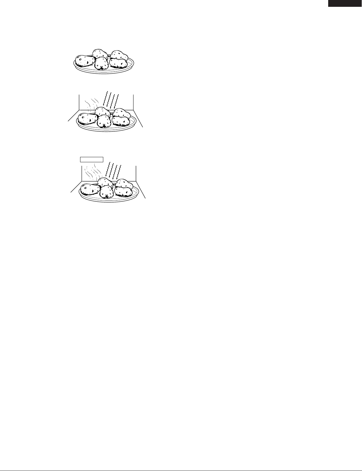
An example of how sensor works:
1. Potatoes at room temperature. Vapor is emitted very
slowly.
MICR
OWAVE
2. Heat potatoes. Moisture and humidity is emitted rapidly.
You can smell the aroma as it cooks.
AH SENSOR
MICROWAVE
3. Sensor detects moisture and humidity and calculates
cooking time and variable power.
Cooking Sequence.
1. Touch SENSOR COOK, REHEAT or POPCORN pad.
When Sensor Cook is touched, to choose menu the
number pad should be touched.
NOTE: The oven should not be operated on SENSOR
COOK, REHEAT or POPCORN immediately after
plugging in the unit. Wait five minutes before cooking
on SENSOR COOK, REHEAT or POPCORN.
2. The coil of shut-off relays (RY1, RY4 and RY5) are
energized, the oven lamp, turntable motor and cooling
fan motor are turned on, but the power transformer is not
turned on.
3. After about 32 seconds, the cook relay (RY2) is energized.
The power transformer is turned on, microwave energy
is produced and first stage is started.
The 32 seconds is the cooling time required to remove
any vapor from the oven cavity and sensor.
NOTE: During this first stage, do not open the door or touch
STOP/CLEAR pad.
4. When the sensor detects the vapor emitted from the
food, the display switches over to the remaining cooking
time and the timer counts down to zero.
At this time, the door may be opened to stir food, turn it
or season, etc.
5. When the timer reaches zero, an audible signal sounds.
The shut-off relay and cook relay are de-energized and
the power transformer, oven lamp, etc. are turned off.
6. Opening the door or touching the STOP/CLEAR pad, the
time of day will reappear on the display and the oven will
revert to an OFF condition.
CONVEC BROIL, CONVEC ROAST, CONVEC
BAKE
CONVEC BROIL, CONVEC ROAST and CONVEC BAKE
will automatically compute the oven temperature, microwave
power and cooking time for broiling, roasting and baking. Set
the desired program by touching one of the CONVEC BROIL,
CONVEC ROAST or CONVEC BAKE pad, and number pad.
Enter the weight by touching the Number pads. When the
START pad is touched, the following operations occur:
1. The COOK indicator will light and the CONV or MIX
indicator will light.
2. The cooking time will appear on the display and start
counting down to zero. The cooking time is adjusted
automatically according to the weight of the food.
3. The shut-off relays (RY1, RY4, RY5 and RY7) are
energized, turning on the oven lamp, turntable motor,
cooling fan motor and convection motor. The power
supply voltage is applied to the heating element.
4. Now, the oven is in the convection cooking mode or
Automatic Mix Cooking condition.
5. When the oven temperature has reached the
programmed convection temperature, the oven goes
into the programmed cooking mode.
6. At the end of the cooking cycle, the damper is returned
to the open position and the oven will go to the off
condition. The cooling fan will remain on until the oven
has cooled.
TIMED DEFROST COOKING
The DEFROST key is a special function key to defrost meats
and poultry faster and better. DEFROST automatically defrosts
roast beef, etc.. When the DEFROST is selected and the food
weight is entered by using the DEFROST pad, the oven will
cook according to the special cooking sequence.
FIRE SENSING FEATURE (MICROWAVE MODE)
This model incorporates a sensing feature which will stop the
oven's operation if there is a fire in the oven cavity during
microwave cooking.
This is accomplished by the LSI repeatedly measuring the
voltage across the temperature measurement circuit (thermistor) during it's 32-seconds time base comparing the
obtained voltage measurements. If the most recent voltage
measured is 100mV greater than the previous voltage
measured, the LSI judges it as a fire in the oven cavity and
switches off the relays to the power transformer and fan
motor. The LSI also stops counting down and closes the
damper plate so that no fresh air will enter the oven cavity.
Please refer to the following section for a more detailed
description.
Operation
The following operation will start 4 minutes after the start
pad is touched. Please refer to the timing diagrams below.
1. The thermistor operates within a 32-seconds time base
and it is energized for three (3) seconds and off for 29
seconds. Two (2) seconds after the thermistor is
energized, the voltage across the temperature
measurement circuit is sampled by the LSI and twenty
one (21) seconds after the thermistor is cut off the LSI
turns on the convection motor for six (6) seconds.
2. The above procedure is repeated. If the difference
between the first voltage measured (in step 1) and the
voltage measured when the procedure is repeated (step
2) is greater than 100mV the LSI makes the judgment
that there is a fire in the oven cavity and will switch off
the relays to the power transformer and fan motor. The LSI
11
VMOR205SS
DMOR205SS
also stops counting down and closes the damper door so
that no fresh air will enter the oven cavity.
3. Once the fire sensor feature has shut the unit down, the
programmed cooking cycle may be resumed by pressing
the "START" pad or the unit may be reset by pressing the
"CLEAR" pad.
IMPORTANT:
During sensor cooking operation, the fire sensing operation sequence will not begin until the AH sensor has
detected vapors and initiated a sensor cooking cycle.
This is because the operation of the convection fan
would interfere with the AH sensor's vapor detection.
3
CONVECTION
MOTOR
THERMISTOR
Sensing
Voltage
0 2 24 30 64 (sec.)
ON
OFF
3 sec.
ON
OFF
ON
OFF
Sensing the voltage across the temperature measurement circuit.
6 sec.
32 (sec.)
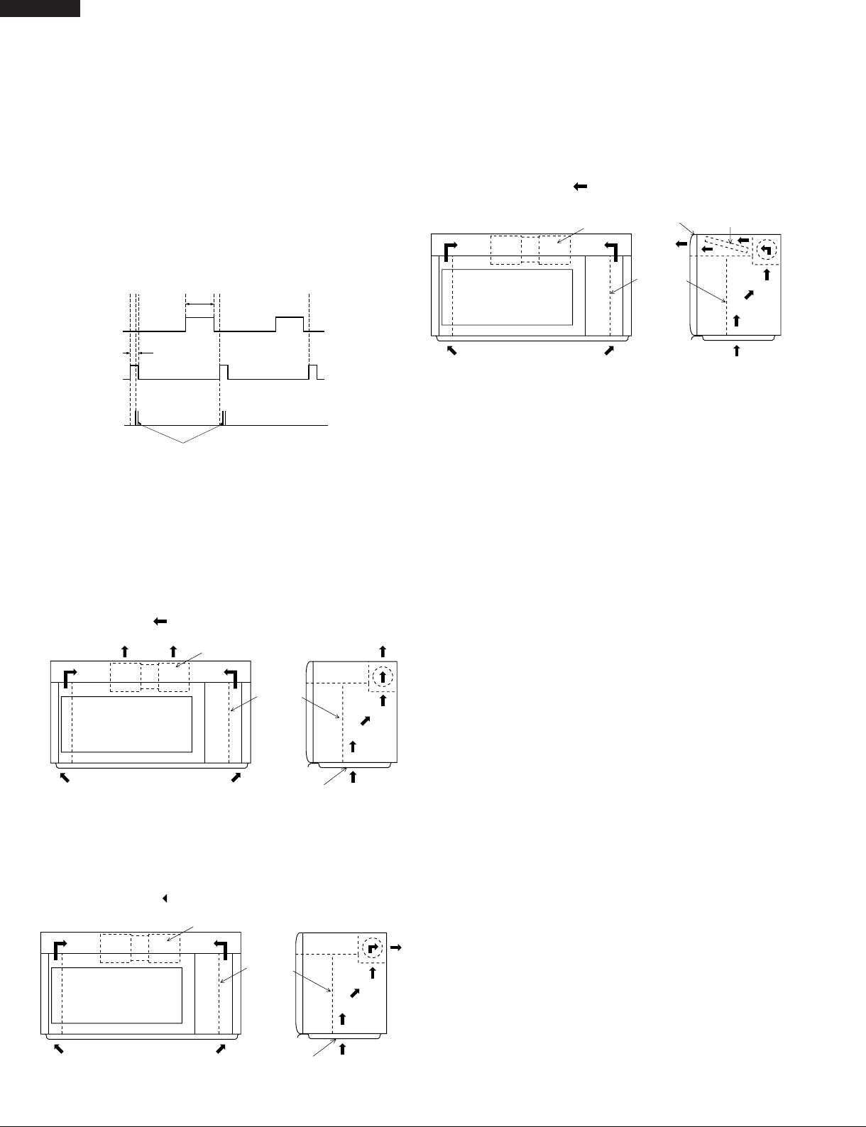
VENTILATION METHODS HOT AIR EXHAUST
1. VERTICAL VENTING
For this venting method, hot air rising from the
conventional range below is drawn in by the hood fan
motor through the grease filters at the right and left sides
of the base cover, up through the right and left side intake
ducts, then discharged vertically at rear center top of the
oven, into the customer's vent system.
3. RE-CIRCULATION (INSIDE VENTING)
The air handing is same as VERTICAL VENTING except
that the final air discharge is directed horizontally
through the upper front of the oven into the kitchen. IN
this case, the accessory charcoal filter lit RK-220 must
be provided to filter the air before it leaves the oven.
: AIR FLOW
HOOD FAN MOTOR
HOOD EXHAUST
LOUVER
HOOD
INTAKE
DUCT R
CHARCOAL
FILTER
: AIR FLOW
HOOD FAN MOTOR
HOOD
INTAKE
DUCT R
GREASE
FILTER
TO DUCTTO DUCT
2. HORIZONTAL VENTING
The air handing is same as VERTICAL VENTING except
that the final air discharge is directed horizontally out
from the top rear of the oven into the customer's vent
system.
: AIR FLOW
HOOD FAN MOTOR
HOOD
INTAKE
DUCT R
TO DUCT
GREASE
FILTER
12
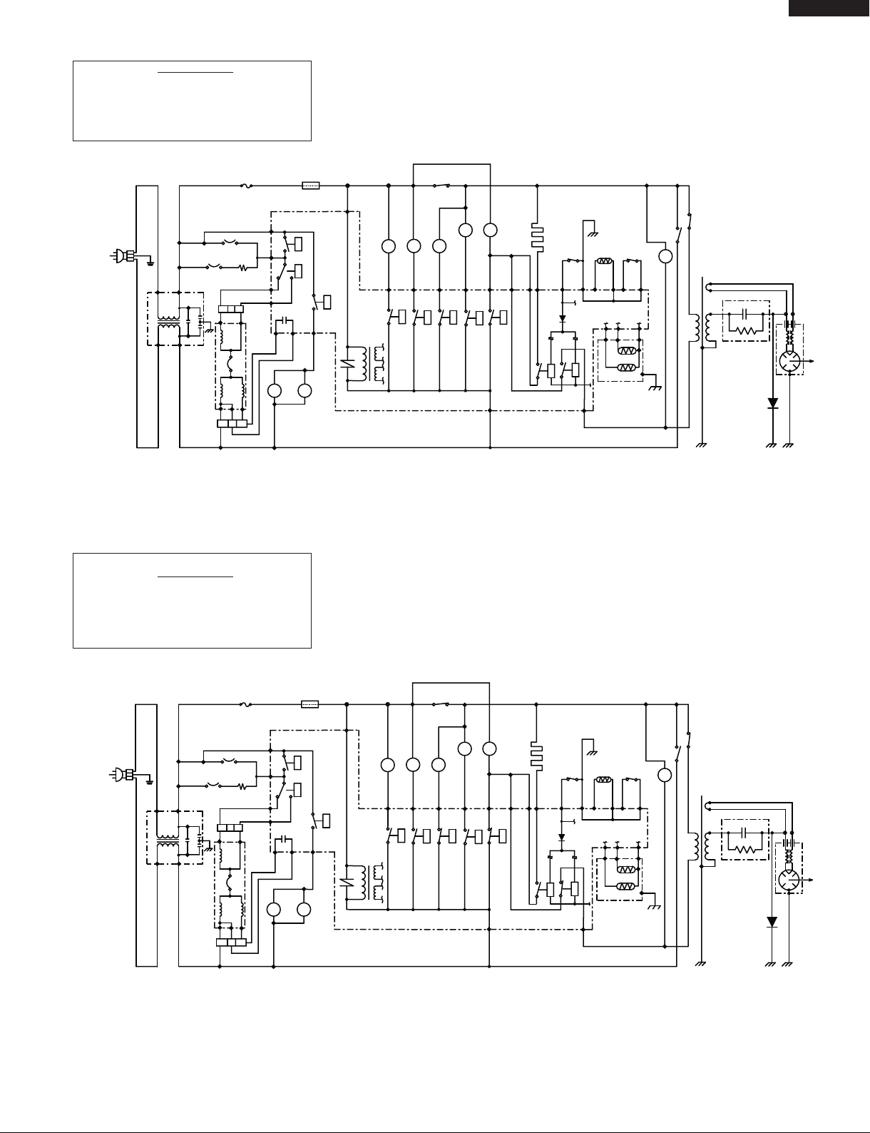
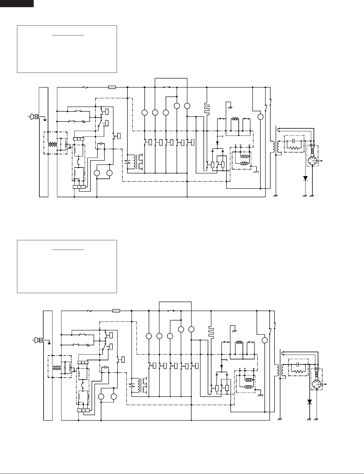
SCHEMATIC
NOTE: CONDITION OF OVEN
1. DOOR CLOSED.
2. CLOCK APPEARS ON DISPLAY.
VMOR205SS
DMOR205SS
MONITOR
RED
FUSE (20A)
BLK
BRN
RESISTOR
WHT
NOISE
BLK
BRN,PNK
PNK
HOOD
MOTOR
RED
C3
BRN
C9
C5
BLU
C7
PPL
HOOD
CAPACITOR
A1
RED
BRN
HL
GRY
YLW
BLK
RED
HOOD FAN
GRN
120VAC
GND
60Hz
WHT
NOTES:
1. Circuits / Wire colors subject to change without notice
2. Terminal with projection or opposite blue mark on lamp socket
3. Only certain models use the absolute humidity sensor.
4. Power transformer top (finish lead) terminal must be connected to the hot wire (RED)
BLK
YLW
(CONV. SIDE)
RED
RED
C2
C1
C3
NOISE
FILTER
GRY
GRY
GRY
must be connected to neutral wire.
THERMAL
CUTOUTS
SCHEMATIC
NOTE: CONDITION OF OVEN
1. DOOR CLOSED.
2. COOKING TIME PROGRAMMED.
3. START PAD TOUCHED.
HOOD
LAMP
MAGNETRON
TEMPERATURE
CONTROL UNIT
RY9
RY10
A3
YLW
BRN
HL
FUSE
ORG
ORG
ORG
A5
RY8
C1
PNK
ORG
YLW
DM
DAMPER MOTOR
BLU
B5
RY6
ORG
ORG
FM
FAN MOTOR
PPL
B3
SECONDARY
INTERLOCK
ORG
TURNTABLE MOTOR
B1 B7
RY5
SWITCH
BLK, BRN
TTM
WHT
BLK
YLW
CM
CONVECTION MOTOR
RY4
ORG
YLW
BLK
ORG
OL
ELEMENT
OVEN LAMP
WHT
BRN
GRY
N.O.
RY1
RY7
BLU
HEATING
BRN
PPL
WHT
PPL
N.O.
COM.
COM.
RY3
RY3
RY2
RY1
RY3
COM.
RY1
GRY
Figure O-1. Oven Schematic - Off Condition
BLK
ORG
GRN
DOOR
SENSING
SWITCH
THERMISTOR
RED
GRN
PNK
BLK
E1
E5
E2
RY2
INTERLOCK RELAY
PRIMARY
N.O.
RY2
WHT
WHT
BLK
E6 E3
F1
AH SENSOR
BLK
MONITOR
SWITCH
DAMPER
SWITCH
BRN
WHT
STIRRER MOTOR
E4
F3
F2
YLW
BLK,BRN
THIRD DOOR
SWITCH
STM
RED
BLU, GRY
WHT
POWER
TRANSFORMER
MAGNETRON
HIGH
VOLTAGE
CAPACITOR
XXX μF
WHT
HIGH
VOLTAGE
RECTIFIER
MONITOR
RED
FUSE (20A)
YLW
BLK
BLK
(CONV. SIDE)
HOOD FAN
THERMAL
CUTOUTS
GRY
BRN
RESISTOR
WHT
BRN,PNK
NOISE
BLK
RED
GRN
120VAC
GND
60Hz
WHT
NOTES:
1. Circuits / Wire colors subject to change without notice
2. Terminal with projection or opposite blue mark on lamp socket
3. Only certain models use the absolute humidity sensor.
4. Power transformer top (finish lead) terminal must be connected to the hot wire (RED)
BLK
YLW
RED
RED
C2
C1
C3
NOISE
FILTER
GRY
GRY
must be connected to neutral wire.
PNK
HOOD
MOTOR
MAGNETRON
TEMPERATURE
FUSE
CONTROL UNIT
RY9
RY10
A3
YLW
BRN
HL
ORG
ORG
ORG
A5
RY8
C1
PNK
ORG
YLW
DM
DAMPER MOTOR
BLU
B5
RED
C3
BRN
C9
C5
BLU
C7
PPL
HOOD
CAPACITOR
A1
RED
HOOD
LAMP
BRN
HL
GRY
RY6
ORG
ORG
FM
FAN MOTOR
PPL
B3
SECONDARY
INTERLOCK
SWITCH
ORG
TTM
TURNTABLE MOTOR
B1 B7
RY5
BLK, BRN
WHT
BLK
YLW
CM
CONVECTION MOTOR
RY4
ORG
YLW
BLK
ORG
OL
WHT
WHT
BRN
GRY
N.O.
RY1
RY7
RY1
COM.
RY1
BLU
GRY
OVEN LAMP
PPL
COM.
RY2
ORG
ELEMENT
HEATING
BRN
PPL
COM.
RY3
GRN
DOOR
SENSING
SWITCH
THERMISTOR
RED
GRN
PNK
N.O.
RY3
RY3
BLK
E1
E5
E2
RY2
INTERLOCK RELAY
PRIMARY
N.O.
RY2
WHT
WHT
BLK
F1
AH SENSOR
E6 E3
BLK
DAMPER
SWITCH
BRN
E4
F3
F2
Figure O-2. Oven Schematic - Microwave Cooking Condition
MONITOR
SWITCH
WHT
STIRRER MOTOR
BLK
YLW
BLK,BRN
THIRD DOOR
SWITCH
STM
RED
BLU, GRY
WHT
POWER
TRANSFORMER
MAGNETRON
HIGH
VOLTAGE
CAPACITOR
XXX μF
WHT
HIGH
VOLTAGE
RECTIFIER
13
VMOR205SS
DMOR205SS
SCHEMATIC
NOTE: CONDITION OF OVEN
1. DOOR CLOSED.
2. CONVECTION PAD TOUCHED.
3. DESIRED TEMP. TOUCHED.
4. START PAD TOUCHED.
MONITOR
RED
FUSE (20A)
YLW
BLK
BLK
(CONV. SIDE)
HOOD FAN
THERMAL
CUTOUTS
GRY
BRN
RESISTOR
WHT
BRN,PNK
NOISE
BLK
RED
GRN
120VAC
GND
60Hz
WHT
NOTES:
1. Circuits / Wire colors subject to change without notice
2. Terminal with projection or opposite blue mark on lamp socket
3. Only certain models use the absolute humidity sensor.
4. Power transformer top (finish lead) terminal must be connected to the hot wire (RED)
BLK
YLW
RED
RED
C2
C1
C3
NOISE
FILTER
GRY
GRY
must be connected to neutral wire.
PNK
HOOD
MOTOR
MAGNETRON
TEMPERATURE
FUSE
CONTROL UNIT
RY9
RY10
A3
YLW
BRN
HL
ORG
ORG
ORG
A5
RY8
C1
PNK
ORG
YLW
DM
DAMPER MOTOR
B5
RED
C3
BRN
C9
C5
BLU
C7
PPL
HOOD
CAPACITOR
A1
RED
HOOD
LAMP
BRN
HL
GRY
SECONDARY
INTERLOCK
SWITCH
BLK
YLW
ORG
ORG
CM
CONVECTION MOTOR
RY4
YLW
BLK
ORG
OL
WHT
WHT
BRN
GRY
N.O.
RY1
RY7
RY1
COM.
RY1
BLU
GRY
ORG
ORG
BLK, BRN
TTM
FM
FAN MOTOR
TURNTABLE MOTOR
BLU
WHT
PPL
B1 B7
B3
RY5
RY6
OVEN LAMP
PPL
COM.
RY2
ORG
ELEMENT
HEATING
BRN
PPL
COM.
RY3
GRN
DOOR
SENSING
SWITCH
THERMISTOR
RED
GRN
PNK
N.O.
RY3
RY3
BLK
E1
E5
E2
RY2
INTERLOCK RELAY
PRIMARY
N.O.
RY2
WHT
WHT
BLK
E6 E3
F1
AH SENSOR
BLK
MONITOR
SWITCH
DAMPER
SWITCH
BRN
WHT
E4
F3
F2
BLK,BRN
STM
STIRRER MOTOR
WHT
BLU, GRY
BLK
YLW
THIRD DOOR
SWITCH
RED
WHT
POWER
TRANSFORMER
HIGH
VOLTAGE
CAPACITOR
XXX μF
HIGH
VOLTAGE
RECTIFIER
Figure O-3. Oven Schematic - Convection Cooking Condition (CONVEC, PREHEAT, BROIL, SLOW COOK)
SCHEMATIC
NOTE: CONDITION OF OVEN
1. DOOR CLOSED.
2. MIX COOKING PAD TOUCHED.
3. DESIRED TEMP. TOUCHED.
4. COOKING TIME PROGRAMMED.
5. START PAD TOUCHED.
NOTE: RY2 and RY3 will alternately close during cook cycle
MAGNETRON
MONITOR
RED
FUSE (20A)
YLW
BLK
BLK
(CONV. SIDE)
HOOD FAN
THERMAL
CUTOUTS
GRY
BRN
NOISE
RESISTOR
WHT
BRN,PNK
BLK
RED
GRN
120VAC
GND
60Hz
WHT
NOTES:
1. Circuits / Wire colors subject to change without notice
2. Terminal with projection or opposite blue mark on lamp socket
3. Only certain models use the absolute humidity sensor.
4. Power transformer top (finish lead) terminal must be connected to the hot wire (RED)
BLK
YLW
RED
RED
C2
C1
C3
NOISE
FILTER
GRY
GRY
must be connected to neutral wire.
Figure O-4. Oven Schematic - Automatic Mix cooking Condition
PNK
HOOD
MOTOR
MAGNETRON
TEMPERATURE
FUSE
CONTROL UNIT
RY9
RY10
A3
YLW
BRN
HL
ORG
ORG
ORG
A5
RY8
C1
PNK
ORG
YLW
DM
DAMPER MOTOR
BLU
B5
RED
C3
BRN
C9
C5
BLU
C7
PPL
HOOD
CAPACITOR
A1
RED
HOOD
LAMP
BRN
HL
GRY
RY6
ORG
ORG
FM
FAN MOTOR
PPL
B3
SECONDARY
ORG
TURNTABLE MOTOR
B1 B7
RY5
INTERLOCK
SWITCH
TTM
WHT
BLK, BRN
BLK
YLW
CM
CONVECTION MOTOR
RY4
ORG
YLW
BLK
ORG
OL
WHT
WHT
BRN
GRY
N.O.
RY1
RY7
RY1
COM.
RY1
BLU
GRY
OVEN LAMP
PPL
COM.
RY2
ORG
ELEMENT
HEATING
BRN
PPL
COM.
RY3
GRN
DOOR
SENSING
SWITCH
THERMISTOR
RED
GRN
PNK
N.O.
RY3
RY3
BLK
E1
E5
E2
RY2
INTERLOCK RELAY
PRIMARY
N.O.
RY2
WHT
WHT
BLK
E6 E3
F1
AH SENSOR
BLK
MONITOR
DAMPER
SWITCH
BRN
WHT
E4
F3
F2
SWITCH
STM
STIRRER MOTOR
BLK
YLW
BLK,BRN
THIRD DOOR
SWITCH
RED
BLU, GRY
WHT
POWER
TRANSFORMER
MAGNETRON
HIGH
VOLTAGE
CAPACITOR
XXX μF
WHT
HIGH
VOLTAGE
RECTIFIER
14
DESCRIPTION AND FUNCTION OF COMPONENTS
VMOR205SS
DMOR205SS
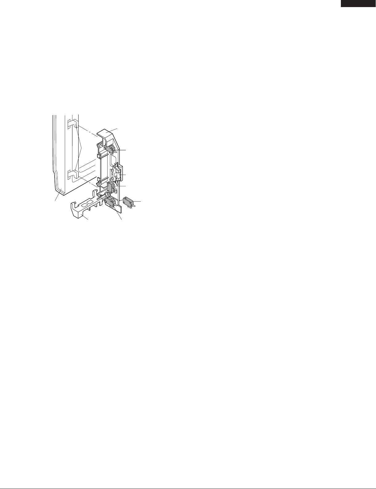
DOOR OPEN MECHANISM
The door is opened by pushing the open button on the control
panel, refer to the Figure D-1.
When the open button is pushed, the open button pushes up
the open lever, and then the open lever pushes up the latch
head. The latch heads are moved upward and released from
latch hook. Now the door will open.
Figure D-1. Door Open Mechanism
LATCH HOOK
DOOR
LATCH
HEADS
OPEN LEVER
DOOR SENSING
SWITCH
MONITOR FUSE
MONITOR
SWITCH
SECONDARY
INTERLOCK
SWITCH
THIRD
DOOR
SWITCH
SECONDARY SWITCH, THIRD DOOR SWITCH &
DOOR SENSING SWITCH
The secondary switch and third switch mounted parrallel to
each other horizontally in the upper positions of the latch
hook, the door sensing switch is mounted horizontally in the
upper position of the latch hook. They are activated by the
latch head on the door. When the door is opened, the switches
interrupt the power to all high voltage components, except the
oven lamp . A cook cycle cannot take place until the door is
firmly closed thereby activating all interlock switches. The
secondary interlock system consists of the door sensing
switch and the primary interlock relay located on the control
circuit board.
MONITOR SWITCH
The monitor switch is activated (the contacts opened) by the
latch head on the door while the door is closed. The switch
is intended to render the oven inoperative, by means of
blowing the monitor fuse, when the contacts of the primary
switch and secondary switch fail to open when the door is
opened.
Functions:
1. When the door is opened, the monitor switch contact close
(to the ON condition) due to their being normally closed.
At this time the secondary interlock relay, primary switch
and secondary switch are in the OFF condition (contacts
open) due to their being normally open contact switches.
2. As the door goes to a closed position, the monitor switch
contacts are first opened and then the door sensing switch,
primary switch and secondary switch contacts close. (On
opening the door, each of these switches operate inversely.)
3. If the door is opened, and the secondary interlock relay,
primary switch and secondary switch contacts fail to
open, the monitor fuse blows simultaneously with closing
of the monitor switch contacts.
CAUTION: BEFORE REPLACING A BLOWN MONITOR
FUSE, TEST THE SECONDARY INTERLOCK
RELAY, SECONDARY SWITCH, DOOR SENSING SWITCH, MONITOR SWITCH AND PRIMARY SWITCH FOR PROPER OPERATION.
(REFER TO CHAPTER "TEST PROCEDURE").
NOTE: MONITOR FUSE, PRIMARY SWITCH AND
MONITOR SWITCH ARE REPLACED AS AN
ASSEMBLY.
TEMPERATURE FUSE (MG)
The temperature fuse located near the waveguide is designed to prevent damage to the magnetron if an over heated
condition develops in the tube due to cooling fan failure,
obstructed air guide, dirty or blocked air intake, etc.
Under normal operation, the temperature fuse remains closed.
However, the temperature fuse will open at 302οF (150οC)
causing the oven to shut down.
THERMAL CUT-OUT (HOOD )
This thermal cut-out located on the base plate right. It is
designed to automatically turn on the hood fan motor
whenever the hot air rising from the conventional range
below causes the temperature at the thermal cut-out to rise
to 140οF (60οC) or higher, thus removing this hot air from
around microwave oven. When the temperature around the
thermal cut-out drops to 113οF (45οC) or lower, the thermal
cut-out shuts off the food fan motor.
TURNTABLE MOTOR
The turntable motor rotates the turntable located on the
bottom of the oven cavity, so that the foods on the turntable
cook evenly during cooking. Turntable will turn in either
direction. The turntable motor can be turned off by touching
TURNTABLE ON/OFF pad.
COOLING FAN MOTOR
The cooling fan motor drives a blade which draws external
cool air. This cool air is directed through the air vanes
surrounding the magnetron and cools the magnetron. This
air is channelled through the oven cavity to remove steam
and vapors given off from the heating foods. It is then
exhausted through the exhausting air vents at the oven
cavity.
HOOD FAN MOTOR
The hood fan motor is a two-speed, single-phase, double
pole induction type, requiring a hood fan capacitor. It is
located outside the upper rear part of the oven cavity, is to
remove, from around the oven, hot air rising from the
conventional electric or gas range over which it is installed.
This air is then expelled either vertically or horizontally
through the customer supplied duct system, or discharged
back into the kitchen.
15
 Loading...