

Page 1

VFR-400 • 5403548 • REV D • 10/07
VFR-400
Installation, Operation, and
Instruction Manual
Releasing Panel for
Sprinkler Systems
All specifi cations subject to revision.
Manual #5403548 Rev D
1
10/07
Page 2

VFR-400 • 5403548 • REV D • 10/07
Contents
Operating Instructions Form ................................................................................................................................................................ 4
Design Guidelines ................................................................................................................................................................................5
General Description ............................................................................................................................................................................. 5
System Features ................................................................................................................................................................................... 5
Visual Indicators .................................................................................................................................................................................. 6
Circuit Parameters ................................................................................................................................................................................ 7
Basic Operation .................................................................................................................................................................................... 9
To Silence Signaling Appliance ......................................................................................................................................................... 11
Remote Annunciator Operation ......................................................................................................................................................... 12
Programming Mode Instructions .......................................................................................................................................................14
Panel Visual Display .......................................................................................................................................................................... 14
VFR-400 Standard Program Information ..........................................................................................................................................17
Wiring Diagram Programs .................................................................................................................................................................20
VFR-400 Custom Program Information ............................................................................................................................................ 45
Installation Instructions ...................................................................................................................................................................... 49
Wire Checkout ................................................................................................................................................................................... 50
Battery Size Calculations ...................................................................................................................................................................51
Battery Size Requirements/Maintenance ...........................................................................................................................................51
2-Wire Smoke Detector Compatibility Data ...................................................................................................................................... 55
Releasing Device Compatibiilty ........................................................................................................................................................ 56
Wire Routing for VFR-400 ................................................................................................................................................................56
Connection Procedure for Battery And Voltage ................................................................................................................................. 58
Connection Drawing for Central And Remote Station ...................................................................................................................... 58
2
Page 3

Notes:
VFR-400 • 5403548 • REV D • 10/07
3
Page 4
VFR-400 • 5403548 • REV D • 10/07
This is the safety alert system. It is used to alert you to potential personal injury hazards. Obey all safety messages
that follow this symbol to avoid possible injury or death.
• The detection and suppression system employing this release panel must be designed by people trained and competent
in the design and layout of fi re alarm and/or suppression systems for special hazard locations. The system shall be designed
and installed in accordance with all local and national codes and ordinances as well as the approval of the Authority Having
Jurisdiction. Only trained, qualifi ed and competent individuals should install, program and/or service the VFR-400.
Competent people would be aware of these warnings, limitations, and requirements.
• High voltage electrocution hazard. Do not handle live AC wiring or work on the device while ac power is active.
This manual is designed to help with the specifi cation, installation, and programming of the VFR-400 release panel. It is
imperative that this manual be completely read and understood before the installation or programming of the panel. Save this
manual for future reference.
• Zones programmed as MANUAL RELEASE will override any cross zoning features. If it is desired to not have a Manual
Release override the cross zoning, program the zone as DETECTION and map accordingly.
*Locate the panel and all system components in the following nominal environment:
*Indoor heated installation only, preferably an interior wall.
*Verify that the wire sizes are adequate for all initiating, notifi cation, and release circuits.
*Make certain the panel is properly grounded.
*Remove all electronic assemblies prior to any drilling, fi ling, reaming, or punching of the enclosure. When possible make all cable
entries from the sides, bottom, or rear of the cabinet. Verify that they will not interfere with the batteries or other components.
*The panel and system must be tested and maintained in accordance with all local and national codes and ordinances.
Operating Instructions Form
1) Fill in the name, address and telephone number of the servicing agency on the instruction sheet provided and
frame and place adjacent to control panel at eye level.
2) The following documentation shall be delivered to the owner or their representative upon fi nal acceptance of the system:
An owners manual and installation instructions covering all system equipment.
Wiring diagrams
A detailed description of the programming and operating sequence of the system.
Fire Alarm System Limitations
Smoke detectors may not detect smoke when the smoke does not reach the detector. Such as smoke within walls, on the other
side of walls, on other fl oors, behind closed doors, explosions, etc. Smoke detectors will not operate if they are not properly
connected to the fi re/release panel. The detectors and bases must be UL/ULC listed as being compatible with the panel. The
detectors have a visible fl ashing light that indicates power is supplied to the detectors.
Notifi cation appliances may not alert people if the people are not able to hear or see the appliances such as if they are in separate
areas of the building or room.
A fi re alarm/release panel will not operate without electrical power. The panel must have suf fi cient backup battery capability to
power the panel for a specifi ed amount of time in the event of an AC power failure. The batteries and release panel shall be tested
and maintained in accordance with the testing and maintenance requirements of NFPA72.
In order for emergency forces, (Fire departments, etc.), to respond to events associated with this panel, the panel must transmit
trouble, supervisory, and alarm signals to a monitoring facility either directly or through a main building fi re panel.
A problem in an audible or visual device may not be apparent when the panel is in a normal condition.
4
Page 5

VFR-400 • 5403548 • REV D • 10/07
Design Guidelines
People trained in the design of special hazard systems shall determine the selection and placement of the initiating devices and
notifi cation appliances connected to the VFR-400. This responsible party shall also be familiar with the premises being protected.
The equipment shall be installed in accordance with the manufacturers instructions, the applicable version of NFPA 72 and all
local codes and ordinances. For systems employing cross zoning of smoke detectors for the activation of the release circuit, this
can include but is not limited to the installation of photoelectric and ionization types of detectors on separate zones. One of each
type of detector on separate zones shall be installed in the coverage area selected for a single detector. The detectors would be
installed in close proximity to each other.
The responsible party shall also determine the theory of operation regarding the programming sequence.
General Description
The model VFR-400 is a listed and approved, microprocessor based fi re control/releasing panel. It is primarily designed for use
as a releasing panel for pre-action, Surefi re®, Firecycle® III, and deluge, water based extinguishing systems. They may also be
used as stand alone fi re control panels. These units comply with NFPA-13, NFPA-15,NFPA-72, and NFPA-750.
The VFR-400 complies with UL Standard 864, ULC S527-77, Canadian Electrical Code Part 1 C22.1, ULC S524, FM, CSFM
and NYMEA.
System Features
• Four Class B (Style B) Initiating zones. Each initiating zone can be set up for any of the following:
· Alarm Zones
· Detection alarm zone
· Waterfl ow
· Linear Heat Detection up to 700 ohms per zone.
· Manual Release
· Viking Firecycle Detectors (Zone 1 only)
· Supervisory Zones
· Supervisory
· Tamper
· Low Air Supervisory
· High Air
· Low Air Alarm
Note: Only zones programmed as Detection, Waterfl ow, Linear Heat, Manual Release, Firecycle and Low
Air Alarm can be mapped to outputs programed as release.
• Remote Annunciator Output for connection to RA-4410RC:
· RS-485 communication, (2-wire shielded cable required)
· Regulated 24VDC annunciator power
• Two Supervisory Zones, Class B (VDC Style B). These zones can be set up for any of the following:
· Supervisory
· Tamper
· Low Air Supervisory
· High Air
• Four Class B (Style Y) Output circuits. Each output can be set up for any of the following:
· Notifi cation Appliance circuit
· Releasing circuit
· Supervisory Bell circuit
· Trouble Bell circuit
5
Page 6
VFR-400 • 5403548 • REV D • 10/07
· Twelve Standard Programs for water based systems or custom program capability
· Releasing Zones can be set up for either normal or cross zoning operation
· All circuits inherently power limited per NEC 760 and UL 864 Section 14.4
· Initiating Circuit Disable feature
· Output Disable feature
· One-Man Walktest feature with automatic 30 minute restoration and releasing circuit disable
· Diagnostic Indicators
· Signal Silence button
· Manual Event scroll buttons
· Automatic resound of silenced trouble signals after 24 hours
· Built-in Trouble buzzer
· Common Relay Contacts for Alarm/Trouble/Supervisory/Waterfl ow
· 32 Character Liquid Crystal Display (LCD)
· 34 LED Display
· AC, Alarm, Supervisory, Trouble, Alarm silenced LED's (Pre-discharge/discharge LED)
· User Generated Banner Message
· User Generated Zone Labeling
· 24 or 90 hour Battery Standby available (Where required by FM and Others)
· 24 Hour Clock
· Password Protection
· Remote annunciator output
· Resettable 4-wire smoke detector power
Options
1) CAM - Module to convert one Class B Indicating Appliance Circuit to one Class A circuit.
2) CA2Z - Module to convert two Class B Initiating Device Circuits to two Class A circuits.
3) ARM-2 - Module to provide two Form C contacts activated by Indicating or Releasing, polarity reversing circuits
4) RA-4410-RC – Remote annunciator provides 34 LED’s for each zone in alarm supervisory or trouble, each output activated or
in trouble, AC power, Power trouble, System trouble, Ground fault, Supervisory, Supervisory trouble, Alarm, Alarm silence
and Pre-discharge/Discharge.
This equipment generates, uses, and can radiate radio frequency energy and if not installed and used in accordance with the
instruction manual, may cause interference to radio communications. It has been tested and found to comply with the limits
for a Class A computing device pursuant to Subpart J of Part 15 of FCC Rules which are designed to provide reasonable
protection against such interference when operated in a commercial environment. Operation of this equipment in a residential
area is likely to cause interference in which case the user at his own expense will be required to take whatever measures may
be required to correct the interference.
Specifi cations
VFR-400 HOUSING
Type - 18 gauge sheet steel with hinged, removable, locked door
Size - 18 1/2" x 14 5/8" x 4 3/4"
Finish - red cabinet with logo.
Knockouts - 4 - ½" and 2 - ¾" on top; 1 - ½" and 1 - ¾" each side; 2 - ½" and 1 - ¾" back
VFR-400 Visual Indicators (Visible with door closed):
AC LED - Green
Alarm Silenced - Amber
System Alarm LED - Red
System Supervisory LED- Amber
System Trouble LED - Amber
Pre-discharge/Discharge LED - Amber
32 Character Alpha-Numeric Liquid Crystal Display (LCD)
Red alarm per zone
Amber trouble LED per zone
Common required systems status LED's
6
Page 7

VFR-400 • 5403548 • REV D • 10/07
LCD
A 2 line 32 character alpha-numeric liquid crystal display shows the condition, status and circuit for all
Alarm, Supervisory and Trouble conditions:
CONDITION STATUS CIRCUIT
Alarm <user Defi ned Message> (Up To 10 Characters)
Trouble Disabled Output #1
Supervisory Acknowledged Output #2
Tamper Silenced Output #3
Low Air Output #4
High Air Battery
Aborted A.C.
Pre-discharging Supervisory
Releasing Zone #1
Released Zone #2
Zone #3
Zone #4
Ground
VFR-400 Visual Indicators
In accordance with ULC S527-99 option B:
LED Annunciator Module
Red LED’s: Initiating Device Circuits Active (4),
Notifi cation/Release Circuits Active (4)
Common Alarm (1)
Green LED: AC Power
Yellow LED’s: Initiating Device Circuits Troubles (4),
Output Circuits Troubles (4)
Supervisory Initiating Zone (4)
Supervisory Bell Output Active (4)
(1) each: Supervisory Zone, Supervisory 1, Supervisory 2, Power Trouble, Supervisory Trouble, System
Trouble, Ground Fault, Discharging/Discharged, Alarm Silenced
CONDITION STATUS LED State
Trouble Non-Silenced Flashing
Trouble Silenced Steady ON
Alarm Non-Silenced Flashing
Alarm Silenced Steady ON
Supervisory Non-Silenced Flashing
Supervisory Silenced Steady ON
Pre-discharge Flashing
Discharged Steady ON
Control Buttons
• Signal Silence - Momentary, silences signaling circuits, (except those activated by zones programmed as WATERFLOW)
• System Reset - Momentary, resets all alarm circuits if condition has been corrected, removes power from initiating device circuits.
• Scroll Up - Scrolls LCD display to most recent events
• Scroll Down - Scrolls LCD display to previous events
NOTE: Buzzer silence is accomplished by scrolling through all events.
Circuit Parameters
All voltages regulated DC
Initiating Device Zones
For connection of dry contact initiating devices and compatible 2 wire smoke detectors. (All values nominal)
• 4 Class B, Style B (Class A Style D module available)*
• Power limited, current limited to protect 2 wire smoke detectors
• Maximum 2 wire 24VDC smoke detector load per zone - 2.5 ma (Use only detectors that are listed in compatibility list.)
• Maximum Line resistance - 100 ohms (Except linear heat detection cable, 700 ohms per zone)
• End-of-Line Resistance - 5.1K
7
Page 8

VFR-400 • 5403548 • REV D • 10/07
• Normal standby current - approximately 4.0 mA
• Standby voltage - 25VDC maximum, 13.4 minimum
• Maximum short circuit current - approximately 36mA
• Maximum Impedance for Alarm - 1400 ohms
• Normal supervisory current - approximately 4mA
• Low current trouble activation - approximately 3.3mA
• Alarm activation current - approximately 10mA
• Ripple voltage - .4 VDC
• Maximum operating voltage range: 22.5 - 25.9V DC
• Frequency - continuous
* In programs 6-9, Zone 1 is a normally closed zone for Firecycle
®
Detectors
Dedicated Supervisory Zones
• For dry contact supervisory devices such as tamper, low air, or high air switches
• 2 Class B Style B circuit, latching
• Power limited, current limited
• End-of-Line resistance - 5.1K ohms
• Ripple Voltage - .1 VDC
• Frequency - continuous
• Maximum voltage - 25VDC
• Maximum short circuit current - approximately 36mA
• Maximum line resistance - 100 ohms
• Normal supervisory current - approximately 4mA
• Low current trouble activation - approximately 3.3mA
• Supervisory current condition - approximately 10mA
(Does not include power for any auxiliary devices)
Notifi cation/Release Circuits
The output circuits of the VFR-400 are Non-coded. This allows the use of visual and audible appliances on the same circuit. If
temporal notifi cation appliances are required for evacuation, selectable tone appliances such as the AMSECO H24W horn or
SH24W Series strobe/horns or a temporal module such as AMSECO TMP1-3A or equivalents should be used.
The notifi cation outputs do not provide synchronization. If synchronization is required, use AMSECO SMD10-3A
synchronization module or equivalent, as identifi ed on page 55. The notifi cation appliances shall be compatible with the sync
module selected. The current requirements of the appliances, wire gauge, and length of wire run determine the maximum
number of appliances that can be connected to one NAC and/or sync module. The maximum cannot exceed 1 amp or whatever
the sync module selected can support, whichever is lower. The sync module shall be installed as per manufacturers instructions.
Equivalent sync modules are shown on page 55.
• 4 Class B Style Y (Class A Style Z module available for notifi cation)
• Reverse polarity upon activation
• Power limited, Current limited
• 24 VDC Regulated, rated 1 amp each, 2.5 amps total for all 4 circuits
• End-of-Line-Resistor - 5.1k ohms
• Frequency - continuous
• Maximum voltage - 27 VDC
• Ripple voltage - .3 VDC
• Maximum resistance for outputs programmed as RELEASING:
1 divided by the current draw of the solenoid when activated
• Normal standy supervisory current - approximately .38mA
• Low current trouble activation - .11mA
• Maximum impedance - 5 Ohms
• High current trouble activation - .63ma
Low/Missing Battery
Causes battery and system trouble if battery falls below 22 volts. Battery circuit is fused and reverse polarity protection is provided.
Input Power
• Universal Input 120VAC, (60 Hz, 165VA) or 220VAC, (50 Hz, 185VA) 15 Amp Branch Line overcurrent
protection required.
• System trouble is also generated if voltage drops below 102V.
Backup Power Requirements
• VFR-400 - Standby 121 mA, alarm 274 mA at 24VDC
8
Page 9

VFR-400 • 5403548 • REV D • 10/07
Service Use
NFPA 13 - Automatic Sprinkler
NFPA 15 - Water Spray Fixed System
NFPA 16 - Foam Water Sprinkler and Foam Water Spray
NFPA 72 - National Fire Alarm Code
• Local
• Remote Station (protected premise unit)
• Central Station (protected premise unit)
NFPA 750 - Water Mist
Listings And Approvals
VFR-400 - UL Standard 864, ULC Standard S527, FM, CSFM and NYMEA
Terminals
• All terminals capable of handling #14 AWG wire
• All terminations have transient protection
• All four initiating device circuit terminals capable of handling linear heat detection.
Relay Outputs
• Common system alarm contacts SPDT rated 3 Amps, 30VDC resistive
• Common supervisory contacts SPST, N.O. rated 3 Amps, 30VDC resistive
• Common system trouble contacts SPDT rated 3 Amps, 30VDC resistive
• Common system waterfl ow contacts SPST, N.O. rated 3 Amps, 30VDC resistive
Auxiliary Power
• Auxiliary Power - 24VDC regulated. Rated 200 mA max. Current limited
• Resettable for 4-wire smoke detectors
Annunciator Connection
• Auxiliary Power - 24VDC regulated. Rated 200 mA max. Current limited for RA-4410-RC Annunciator, non-resettable power
• RS-485 For connection to RA-4410-RC remote annunciator
• Maximum 2000' with 22 AWG, 4000' with 20 AWG shielded cable
Optional Accessories
CA2Z module (Class A initiating device circuit)
Converts two Class B initiating device circuits to two Class A circuits.
CAM Module (Class A Indicating Appliance Circuit)
Converts indicating appliance circuit from Class B to Class A. One model CAM (Class A Module) is required
for each circuit. (Do not use this on an output programmed as “TROUBLE BELL”.)
ARM-1/ARM-2 Module (Auxiliary Relay Module)
Activated by 24VDC Indicating and/or Releasing, polarity reversing circuits. The module provides a non-supervised DPDT Relay
that can be used for fan shutdown, door release, elevator recall, etc.
RA-4410RC (Remote Annunciator)
Connects to RS-485 & 24VDC terminals. Provides 34 LED’s for each zone in alarm supervisory, or trouble, each output activated
or in trouble, AC power, Power trouble, System trouble, Ground fault, Supervisory, Supervisory trouble, Alarm, Alarm silence and
Pre-discharge/Discharge.
Basic Operation
In addition to the following events, the panel also provides an output via the RS-485 terminals to the RA-4410-RC remote
annunciator to light the appropriate indicators. See remote annunciator operations, page 12. In addition, the remote annunciator
has a silenceable buzzer that sounds on supervisory or trouble conditions.
Initiating Device Circuits Alarm Condition
An increase of current on any alarm initiating device circuit to approximately 10 mA or greater will result in the following:
Alarm (Except zones programmed as LOW AIR ALARM):
1) Activation of the common alarm relay contacts.
2) Activation of the output circuit(s) which are mapped to the initiating device circuit(s). Providing all zone(s)
necessary for the activation of those circuits is in alarm
3) “ALARM” and zone # displayed on LCD.
4) Activation of the red ALARM LED in a fl ashing mode as well as corresponding zone. NOTE: The ALARM LED will continue
to fl ash until the Signal Silence button is pushed. The silence button will remove power from all outputs set up as Indicating
except those activated by zones programmed as Waterfl ow.
5) Activation of zones programmed as waterfl ow will operate the common waterfl ow relay contacts in addition to the above.
Note: If Zone 1 is programmed as Firecycle, an open circuit will result in the above.
9
Page 10
VFR-400 • 5403548 • REV D • 10/07
Do not silence signals until all occupants are
evacuated to a safe area.
Low Air Alarm
1) Operation of supervisory relay contacts and local buzzer.
2) Activation of the notifi cation appliance circuit(s) or releasing circuit(s) which are mapped to the initiating device circuit(s).
Providing all zone(s) necessary for the activation of those circuits is in alarm
3) LOW AIR ALARM and <CIRCUIT #> displayed on LCD.
4) Activation of the amber supervisory LED in a fl ashing mode. NOTE: The supervisory LED will continue to fl ash until all
events in the SUPERVISORY queue are viewed. This is accomplished by scrolling through all of the events by use of the
scroll up and scroll down buttons. The LED will go steady after all alarm events have been viewed.
Supervisory
An increase of current to approximately 8 mA or greater on the supervisory initiating device circuit(s) or disabling an output
programmed as releasing will result in the following:
1) Operation of supervisory relay contacts and local buzzer.
2) Operation of any output circuits that have been described as SUPERVISORY BELL.
3) “SUPERVISORY”, “TAMPER”, “LOW AIR”, or “HIGH AIR” and <CIRCUIT> displayed on LCD.
4) Activation of the amber SUPERVISORY LED in a fl ashing modes well as the corresponding zone LED. NOTE: The
SUPERVISORY LED will continue to fl ash until all events in the SUPERVISORY queue are viewed. This is accomplished by
scrolling through all of the events by use of the scroll up and scroll down buttons. The LED will go steady after all supervisory
events have been viewed.
Trouble Conditions
Initiating Device Circuits
A decrease of current to approximately 3.3 mA or programming the zone as disabled on any initiating device circuit will result in
the following:
1) Activation of trouble relay contacts and local buzzer.
2) Operation of any output circuits which have been described as TROUBLE BELL.
3) “TROUBLE” and <CIRCUIT> displayed on LCD.
4) Activation of the amber TROUBLE LED in a fl ashing mode as well as corresponding zone. NOTE: The TROUBLE LED
will continue to fl ash until all events in the TROUBLE queue are viewed. This is accomplished by scrolling through all of the
events by use of the scroll up and scroll down buttons. The LED will go steady after all trouble events have been viewed.
Note: When the circuits are operated in the Class A mode any trouble condition will require manual operation of the reset switch
to restore the panel to normal after the fault has been removed.
A complete loss of power will result in the transfer of the common system trouble relay contacts.
If Zone 1 is programmed as Firecycle, an increase in current to 10 mA or greater will result in the above.
Notifi cation Appliance/Releasing Circuits
An increase of current to approximately 0.63 mA or a decrease in current to approximately 0.11 mA on any output circuit or
connecting an indicating appliance backwards, or disabling an output will result in the following:
1) Activation of trouble relay contacts and local buzzer.
2) Operation of any output circuits which have been programmed as TROUBLE BELL. If this output is in trouble, a
TROUBLE BELL on this output may not function correctly, depending on the type of trouble.
3) “TROUBLE” and “OUTPUT #” <CIRCUIT NO.> displayed on LCD.
Note: A current in excess of 2.5 Amps, when the panel is in the alarm condition, will result in an output trouble as described above.
A problem in an audible or visual device may not be apparent when the panel is in a normal condition. If the circuit indicates a
trouble condition when the panel is in an alarm condition the problem must be located and corrected.
10
Page 11

VFR-400 • 5403548 • REV D • 10/07
Ground Fault
A short between any circuit and earth ground will result in the following:
1) Activation of trouble relay contacts, trouble LED in a fl ashing mode, and local buzzer.
2) Operation of any output circuits which have been described as TROUBLE BELL.
3) “TROUBLE” and “GROUND” displayed on LCD.
Loss Or Reduction Of AC Power
A reduction in the AC input voltage will result in the following:
1) Activation of amber trouble LED in a fl ashing mode and local buzzer.
2) Operation of any output circuits which have been described as TROUBLE BELL.
3) “TROUBLE” and “A.C.” displayed on LCD.
4) LCD Backlight will be extinguished.
5) Loss of green AC LED.
6) The trouble relay contacts will transfer after 90 minutes.
Low Battery Voltage
Loss of or reduction of battery voltage to 22 volts will result in the following:
1) Activation of common trouble relay contacts, amber trouble LED in a fl ashing mode and local buzzer.
2) Operation of any output circuits that have been described as TROUBLE BELL.
3) “TROUBLE” and “BATTERY” displayed on LCD.
Loss Of Auxiliary Power Output
Loss of output of the auxiliary power will result in the following:
1) Activation of trouble relay contacts, trouble LED in a fl ashing mode and local buzzer.
2) Operation of any output circuits that have been described as TROUBLE BELL.
3) “TROUBLE” and “AUX LOW” displayed on LCD.
4) Activation of amber POWER TROUBLE LED.
5) Activation of amber SYSTEM TROUBLE LED.
To Silence The Buzzer Or Outputs That Have Been Described As Trouble Or Supervisory Bell
Press the scroll up or scroll down buttons. Once all events in the trouble or supervisory queue have been viewed, the buzzer and
appropriate output will silence. The applicable system TROUBLE or SUPERVISORY LED will change from fl ashing to steady.
Note: Any continuous trouble conditions that have been silenced automatically resound 24 hours after the fi rst trouble condition was silenced.
11
Page 12
VFR-400 • 5403548 • REV D • 10/07
To Silence A Signaling Appliance
Press the SIGNAL SILENCE button. All silencable outputs will de-activate. A trouble condition will be created and the amber
Alarm Silenced LED will light.
Where audible and/or visual indicators are being used as an evacuation signal, do not silence an alarm condition without
investigating and determining that an emergency condition does not exist.
Notes: 1) Alarms initiated from zones that are in the waterfl ow mode cannot be silenced. The panel must be reset to silence
audible alarm devices.
2) If silenceable waterfl ow indication is desired it must be programmed as conventional alarm and annunciated on the
zone identifi cation portion of the LCD.
To Reset an Alarm or Supervisory Condition
1) Determine the cause of the alarm condition and if necessary remove the cause.
2) Press the reset button.
To Reset A Trouble Condition
1) Determine the cause of the trouble condition and remove the cause.
2) This circuit is self-restoring. When all trouble conditions are removed all indications will return to normal.
Note: When an initiating device zone is operated in a Class A (Style D) mode any trouble condition will require manual
operation of the reset switch to restore the panel to normal after the fault has been corrected.
Lamp Test
When the panel is in a Normal Condition, pushing the top two buttons will illuminate all of the LED's and display for
approximately one second.
Remote Annunciator Model RA-4410RC Operation
Red LED’s: Initiating Device Circuits Active (4)
Notifi cation/Release Circuits Active (4)
Common Alarm (1)
Green LED’s: AC Power
Yellow LED’s: Initiating Device Circuits troubles (4)
Output Circuit Troubles (4)
supervisory Bell Output Active (4)
(1) each: Supervisory Zone, Power Trouble, Supervisory T rouble, System T rouble, Ground Fault, Dischar ging/Discharged, Alarm Silenced
RA-4410RC
ZONE 1
ZONE 2
ZONE 3
ZONE 4
AC POWER
POWER TBL
SYSTEM TBL
SUP TBL
GROUND FAULT
OUTPUT 1
OUTPUT 2
OUTPUT 3
OUTPUT 4
SUPERVISORY 1
SUPERVISORY 2
COMMON ALARM
ALARM SILENCE
STEADY: DISCHARGE
FLASHING: PRE-DISCHARGE
LAMP TEST
DWG# 3550-17VKG
Basic Operation
The appropriate LED fl ashes to indicate a change of status on the panel. A trouble or supervisory condition will fl ash
the appropriate Yellow LED indicating the location of the condition. If any outputs are programmed as TROUBLE or
SUPERVISORY BELL, that Yellow output LED will fl ash indicating the output is activated. Pressing the BUZZER SILENCE
button on the panel changes the fl ashing zone Amber LED to steady on and turns the fl ashing Yellow output LED off.
An alarm or low air alarm condition will fl ash a Red LED indicating the zone in alarm and any outputs mapped to that zone that
12
Page 13
VFR-400 • 5403548 • REV D • 10/07
have activated. Pressing the SIGNAL SILENCE button changes the fl ashing Red Zone LED to steady on and the fl ashing Red
Output LED mapped to that zone off unless the output is programmed as RELEASE. In addition, the Yellow ALARM/ SILENCE
LED will light.
Any zone programmed as WATERFLOW is considered non-silenceable so the signal and buzzer silence buttons will have no
effect on the fl ashing zone and output LED's. A buzzer on the annunciator sounds for any trouble condition. When the panel
has a trouble or supervisory condition, pressing the SILENCE/LAMP TEST button silences the condition at the panel and all
annunciators. When the panel is in a normal state, pressing the SILENCE/LAMP TEST button can be used to test the LED's.
The release panel supervises and communicates with the annunciator via separate connections for the RS-485 communication and
24VDC power requirements of the RA-4410-RC. Separate cables should be used for power and communication. Shielded cable
shall be used for the communication line. Up to three annunciators can be connected to one panel. A rotary switch is provided on
the panel to indicate how many annunciators are connected. Another rotary switch is on the annunciator to set the address. The
annunciators must be addressed consecutively. See page 54 for wiring information. Refer to bulletin #8840024 for installation
instructions and maximum wire run.
Test Procedure
The system should be inspected, tested, and maintained in accordance with NFPA-72 National Fire Alarm Code, Chapter 10 and
any other requirements of the local authority having jurisdiction.
Test Procedure (Canada)
The system should be inspected, tested, and maintained in accordance with ULC Standard CAN/ULC-S536 and any other
requirements of the local authority having jurisdiction.
Testing should be done as a minimum as described below:
1) Notify the fi re department or other receiving station if alarm, supervisory and/or trouble signals are transmitted.
2) Notify the proper building personnel so that audible and/or visual signals can be ignored.
3) If the release panel is monitored by a building fi re alarm panel, take appropriate action to eliminate any unwanted events.
4) Momentarily open each of the following circuits.
a) Each initiating device zone
b) Supervisory circuit
c) Indicating Appliance/Releasing circuit - observe that this results in a trouble condition and all indicators operate as
described in the appropriate preceding section for the particular circuit that is faulted.
5) Move the PROGRAM switch down. The LCD should respond: “LOOK AT HISTORY?”. Press the FUNCTION button
until the display reads PASSWORD=000. Enter password if changed from factoy or press the SET button three times. Press
the FUNCTION (bottom) button until the LCD reads “SYSTEM MODE: NORMAL”. Press the SELECT button. The LCD
will read “SYSTEM MODE:
ONE MAN WALKTEST”. Press the SET button then move the PROGRAM switch up. The panel will respond with “ONE
MAN W ALKTEST” and the time. The trouble LED will light. Any output described as “RELEASING” will automatically be disabled.
Failure to enter the walktest mode and subsequent operation
of initiating zones may result in a release.
After 30 minutes of no activity in the walk test mode the panel automatically reverts to normal operation.
6) Operate each initiating device on all zones. All audible and visual alarm devices should operate for about 3 seconds. Then the
system will automatically reset allowing the user to go to the next initiating device.
7) Operate each initiating device on the supervisory circuit. Observe that all the indications described in the section on
supervisory conditions occur.
8) Move the PROGRAM switch down again. The LCD should respond: “LOOK AT HISTORY?”
Press the FUNCTION button until the display reads PASSWORD=000. Enter password if changed from factory or press the
SET button three times.
Press the FUNCTION (bottom) button until the LCD reads: “SYSTEM MODE: ONE MAN WALKTEST”
Press the SELECT (middle) button. The LCD will read: “SYSTEM MODE: NORMAL”
Press the SET (top) button then restore the PROGRAM switch to the up position. The LCD will show the normal banner message.
9) All audible and visual indicators should be off.
10) Notify all building, fi re department, and/or other receiving station personnel that the test has concluded.
Maintenance: Test batteries per local and national standards. At a minimum replace batteries every four (4) years or sooner
depending on test results. The date of purchase shall be marked on all batteries.
13
Page 14
VFR-400 • 5403548 • REV D • 10/07
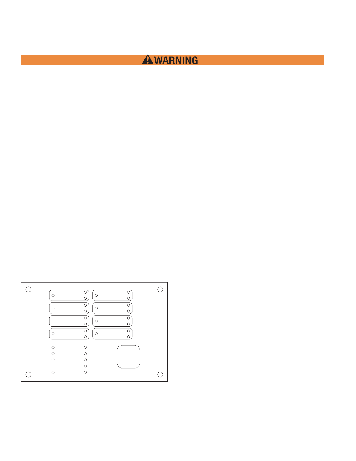
Programming Mode Instructions
To use the Programming Mode push the program switch down (see drawing below).
Panel Visual Display
As a general rule, the following applies on the Programming Mode buttons:
The top button (SET) sets the message on the display into the memory.
The middle button (SELECT) scrolls through the selections available for the function displayed.
The bottom button (FUNCTION) allows the user to skip the function without changing the program.
OUTPUT 2
OUTPUT 1
OUTPUT 3
OUTPUT 4
SUPERVISORY 1
SUPERVISORY 2
COMMON ALARM
ALARM SILENCE
STEADY: DISCHARGE
FLASHING:
PRE-DISCHARGE
PROGRAM
SELECT
FUNCTION
MODE
SET
RUN
MODE
SCROLL-UP
BUZZER SILENCE
LAMP
}
TEST
SCROLL-DOWN
BUZZER SILENCE
SIGNAL SILENCE
SYSTEM RESET
DWG# 3550-18VKG
RUN
PROGRAM
ZONE 1
ZONE 2
ZONE 3
ZONE 4
AC POWER
POWER TBL
SYSTEM TBL
SUP TBL
GROUND
FAU LT
VIEWING ANGLE
To program, push the Program Switch down.
There is no capability to back up screens in the program mode. If a mistake was made during programming, move the program
switch back up, then move it down and start from the beginning.
To exit the program mode at any time, move the Program Switch up.
When the programming switch is down (see Panel Visual Display) the following will appear in the display window:
LOOK AT
HI STORY?
History
To examine the HISTORY press the top button, the display window will show the time and date of the last event or action. To skip
to the next function or to exit history, press the FUNCTION (bottom) button.
SET Press the SET button to discover the time and date of the last event or action and to scroll forward.
SELECT To scroll back, press the SELECT button.
FUNCTION To exit or skip HISTORY, press the bottom button.
14
Page 15

VFR-400 • 5403548 • REV D • 10/07
SET TI ME?
Date/Time
SELECT To change the time, press the SELECT button.
FUNCTION To exit to the next function, press the bottom button.
If the middle button is pushed, the date and time will appear in the display window:
01/ 05/ 2007
The date is shown at the top and the time at the bottom of the display window. “MINUTES” indicates that the user can now
change the minutes.
SET Pressing the SET button will decrease the minutes
SELECT Pressing the SELECT button will increase the minutes.
FUNCTION When fi nshed setting the minutes, Press the bottom button. The minutes will change to hours.
Continue this process and change the DAY, MONTH and YEAR. When you have fi nished changing the year, press the
FUNCTION (bottom) button. A display similar to the following will appear:
PASSWORD=000
^
Password
This display prevents unauthorized programming of the panel by requiring the user to enter the proper password. To select the
appropriate number for the space indicated by the ^ symbol, press the SELECT button. When the proper number is displayed
press the SET button to set the number and move to the next space. If the wrong password is entered, the panel will display "Push
Programming Switch Up". All panels are shipped from the factory with a password of 000. If the password is lost contact Potter.
SET After selecting the desired number, press the SET button to set and move to the next number.
SELECT Press the SELECT button to scroll through the numbers.
FUNCTION Pressing the bottom button will have no effect.
15
Page 16
VFR-400 • 5403548 • REV D • 10/07
After entering the correct password, a display similar to the following will appear:
INIT ZONE #1
ENABLED
Zone Disabled/Enabled
This display allows the user to ENABLE or DISABLE Initiating zones. This display window shows that initiating ZONE #1 is
enabled. To toggle from ENABLED to DISABLED or visa versa, press the SELECT button.
SET After selecting ENABLED or DISABLED, press the SET button to set and move to the
next zone.
SELECT Press the SELECT button to toggle between ENABLED or DISABLED.
FUNCTION To skip to the next function, press the bottom button.
After selecting all four zones or pressing the FUNCTION (bottom) button, the following will appear in the display window:
OUTP UT #1
ENABLED
Output Enable/Disable
This display allows the user to ENABLE or DISABLE any of the output circuits.
SET After selecting ENABLED or DISABLED, press the SET button to set and move to the next output.
SELECT Press the SELECT button to toggle between ENABLED or DISABLED.
FUNCTION To skip to the next function, press the bottom button.
After selecting all four outputs or pressing the FUNCTION (bottom) button, the following will appear in the display window:
Disabling any input or outputs will create a trouble condition on the panel.
Disabling a releasing circuit will create a supervisory condition.
SYST EM MODE:
NORMAL
16
Page 17
VFR-400 • 5403548 • REV D • 10/07
One Man Walktest
This display allows the user to select system mode NORMAL or ONE MAN WALKTEST by pressing the SELECT button to
toggle back and forth from NORMAL to ONE MAN WALKTEST. When the desired mode is displayed, press the SET button.
If ONE MAN WALKTEST is selected for test purposes, the display must be restored to the NORMAL setting after the test is
completed by toggling to it using the SELECT button.
After 30 minutes of no activity the panel
automatically reverts to normal.
SET After selecting NORMAL or ONE MAN WALKTEST, press the SET button to set that mode.
SELECT Press the SELECT button to toggle between NORMAL and CROSS ZONED.
FUNCTION Press the bottom button to skip to the next function.
After selecting the operating mode or pressing the FUNCTION button a display similar to the following will appear in the display
window:
PROGRAM #1
VFR-400 Standard Program Information
The VFR-400 has 12 standard programs which are detailed in the following pages. Selecting one of these programs will
automatically program every function of the panel except the custom banner and zone message functions.
Notes:
The release discharge time is continuous for all programs not employing the Firecycle feature. The default soak timer for the
Firecycle feature is continuous.
The following is an explanation of how the various programs operate and information about the types of
devices that are to be connected to the input and output zones. If none of the standard programs are acceptable for the installation
required, select the custom program #0 then press the SET button. This will allow the user to custom program the panel. Turn to
page 45 for custom program information.
Type Description
Alarm Zones Detection Smoke Detectors, Spot Type Heat Detectors
Waterfl ow PS10 Pressure Switch
Linear Heat Cable Type Heat Detectors
Manual Release Pull Stations
Firecycle Viking normally closed heat detectors
Supervisory Zones Supervisory Valve Tamper, Low Air, High Air, Room Temperature
Low Air supervisory Low Air Switch
High Air High Air Switch
Tamper Valve Tamper Switch
Low Air Alarm * PS10, PS40
* Not available on Supervisory Zones Sup 1 or Sup 2
17
Page 18
VFR-400 • 5403548 • REV D • 10/07
Outputs Alarm 24VDC Bells, Horns, Strobes, to indicate an alarm condition.
Release Solenoid Valve, Squib, Releasing Mechanism
Supervisory 24VDC Bells, Horns, Strobes, to indicate a supervisory condition.
Trouble 24VDC Bells, Horns, Strobes, to indicate a trouble condition.
To program the VFR-400 to operate with one of the following 12 standard programs:
1) Press SELECT button to scroll to the program number (#1 thru #12) you desire.
2) Press SET button.
3) Turn to page 48 to program the banner message and to fi nish programming the panel.
SET After selecting the proper program number, press the SET button to set the program and move to the next function.
SELECT Press the SELECT button to scroll through the programs.
FUNCTION Press the bottom button to skip to the next function.
After selecting the desired program number with the middle button, SET must be pressed to set the program.
When the Firecycle programs (6-9) are selected, only outputs #3 and #4 can be selected as releasing.
If the Firecycle feature is used, Firecycle heat detectors must be connected to Zone 1. Zone 1 follows the status of the Firecycle
detector. When the detector resets, a soak timer is initiated. The default soak timer is continuous. The soak timer is user
selectable to 30, 60, or 90 seconds or 2 - 20 minutes in 1 minute increments.
18
Page 19

This page intentionally left blank.
VFR-400 • 5403548 • REV D • 10/07
19
Page 20

VFR-400 • 5403548 • REV D • 10/07
PROGRAM #1
For One Sprinkler System
Viking Sprinkler
System T ypes
2 Release Zones,
Waterfl ow Zone,
& Manual Release
Zone
1. Single Interlocked Preaction System with Electric Release
2. Deluge System with Electric Release
3. Non-Interlocked Preaction System with Electric Release
4. Double Interlocked Preaction System with Electric/Pneumatic Release
ZONES (Initiating Circuits)
OUTPUTS
(Indicating Circuits)
SUP 1 SUP 2 #1 #2 #3 #4
Low Air
Supervisory Zone
Valve Tamper
Supervisory Zone
Conventional
Detection Zone
Conventional
Detection Zone
Waterfl ow
Zone
Manual
Release Zone
#1 General Alarm X X X X
#2 W aterfl ow X
#3 Release Solenoid X X X
#4 Supervisory Bell X X
OPERATION DESCRIPTION
Inputs: 2 Conventional Detection zones, 1 Waterfl ow zone, 1 Manual Release zone, 2 Supervisory zones
Outputs: 1 General Alarm, 1 Waterfl ow Alarm, 1 Solenoid Release, 1 Supervisory Bell
Operation: Activation of Conventional Detection zone #1 or #2 or Manual Release zone #4 will activate output #3
(Release Solenoid) and output #1 (General Alarm)
Activation of Waterfl ow zone #3 will activate output #2 (Waterfl ow) and output #1 (General Alarm)
Activation of Low Air Supervisory zone #1 or Valve Tamper Supervisory zone #2 will operate output #4
(Supervisory Bell).
NOTES:
1. Connect EOL Diode assembly IN SERIES as shown with Solenoid on output #3 (Release Solenoid). Black wire to positive
terminal on panel and Red wire through Solenoid to negative terminal on panel.
2. Polarity is shown on indicating circuits in normal (no alarm) condition. Polarity reverses when ouptut is activated.
3. Leave EOLR (provided) on all unnused circuits.
4. See the instruction manual for circuit information, panel limits, and battery sizing.
5. For wire routing instructions through the releasing panel, see Note 3 on page 56 of the instruction manual.
6. See instruction manual for proper programming.
7. See instruction manual for list of compatible smoke detectors.
8. See specifi c system type data page for proper pressure switch settings.
20
Page 21

VFR-400 • 5403548 • REV D • 10/07
H
OT - BLACK
N
EUTRAL-WHITE
EARTHGROUND-G
LOWAIR
RESSURE
P
OR
SUPERVIS
Y
ALVE
V
SWITCH
T
AMPER
2
0947
SUPERVISO
EOLR
EOLR
5.1K
5.1
K
24VNRDC
V
ZO
ZO
ZONE 3
ZO
C
POWE
A
POWERTBL
SYSTEMTBL
S
UPTB
GRO
UND
F
LT
U
A
I
EWING
NE 1
NE 2
N
L
A
120OHM
E
R
N
G
4
LE
485
OUTPUT
O
OUTPUT
OUTPUT4
SUPERVISORY 1
SUPERVISORY
COMMONALA
ALAR
MSI
EA
:
Y
S
D
DISCHAR
T
LASHIN
G:PRE-
F
UTPUT
LEN
DISC
D
C
F R-40
P1
SU
SUP
2
0
AUX.POWERRS-
24VR
1
V
2
3
P
MOD
2
RM
CE
D
E
G
E
S
E
HAR
G
SELECT
FUNCTI
O
R
T
N
OGRAM
E
RU
N
MOD
SCROLL-UP
UZZERSILENCE
B
LAMP TEST
CROLL-DOWN
S
BUZZER
I
S
G
SYSTEM
E
SIL
ENCE
I
S
NAL
LENCE
RES
ET
R
EEN
N
L
RUN
PROGRA
M
R
CONVE
Y
NTI
DETECTION
R
EOL
5.1K
N
O
1
CONVEN
DETECTIO
AL
ZONE2ZONE
WAT
ER
TIONAL
E
OLR
1K
.
5
MANUAL
FLOW
N
RELEASE
TCH
SWI
STATION
0
0947
EOLR
OLR
E
5.1K
5.1
K
ZONE
O
Z
E
N
ZONE4
3
2
ZONE
1
WTR
T
LE SU
OUTPU
BLACK
RED
5.
1K
E
OLR
AL
ATERFLOW
W
M
T2 OUTPUT3 OUTPUT4
BLACK
RED
EO
DIOD
ASS
RELEASE
SOLENO
BLACK
5.1K
L
E
EO
LR
Y
SU
PERVISORY
BEL
ID
RED
RED
L
OUTPUT1
AT-
BAT
B
+
BLACK
RED
BLACK
5.1K
EOLR
GENER
ALAR
COM
ROUB
N
ALARM
COM
O
NC
O
ELAYCONTAC
R
RY CONTACTSRATED AT3A,30VDC
D
CO
TS
FLW
PV
O
M
NO
MNC
ON
C
N
1. Run fi eld wiring and ensure connections are proper by metering wires. Resistance reading should be 5.1K ohms with end-of-
line resistor (EOLR) at last device. The end-of-line resistor is located on the mother board. Remove as needed. Leave factory
installed EOLR on all unused circuits.
2. Connect one circuit at a time and apply AC power.
3. Connect batteries to the panel.
4. Once last connection is made, move Program switch down.
5. Press the FUNCTION (bottom) button until the display reads “PASSWORD = 000”.
6. To enter a password, press the SELECT button until the proper number is displayed above the ^ symbol, then press the SET button
to move to the next digit. After entering the third number the display will change. (All panels are shipped with a 000 password.)
7. Press the FUNCTION (bottom) button until the display reads “PROGRAM #1”.
8. Press the SELECT button until the display reads “PROGRAM #1”.
9. Press the SET button.
10. The panel is completely programmed except for the custom banner and zone messages. Move the program switch back up.
21
Page 22

VFR-400 • 5403548 • REV D • 10/07
PROGRAM #2
For Two Sprinkler Systems Operating Independantly From Each Other
Viking Sprinkler
System T ypes
2 Split Release
Zones and 2
Waterfl ow Zones
1. Single Interlocked Preaction System with Electric Release
2. Deluge System with Electric Release
3. Non-Interlocked Preaction System with Electric Release
4. Double Interlocked Preaction System with Electric/Pneumatic Release
ZONES (Initiating Circuits)
OUTPUTS
(Indicating Circuits)
SUP 1 SUP 2 #1 #2 #3 #4
Valve Tamper
Supervisory Zone
for Systems 1 & 2
Low Air
Supervisory Zone
for Systems 1 & 2
Conventional
Detection Zone
for System 1
Conventional
Detection Zone
for System 2
Waterfl ow
Zone for
System 1
Waterfl ow
Zone for
System 2
#1 General Alarm X X X X
#2 Release Solenoid #1 X
#3 Release Solenoid #2 X
#4 W aterfl ow XX
OPERATION DESCRIPTION
Inputs: 2 Conventional Detection zones, 2 Waterfl ow zones, 2 Supervisory zones
Outputs: 1 General Alarm, 1 Waterfl ow Alarm, 2 Solenoid Release
Operation: Activation of Conventional Detection zone #1 will activate output #2 (Release Solenoid #1) and
output #1 (General Alarm)
Activation of Waterfl ow zone #3 will activate output #2 (Waterfl ow) and output #1 (General Alarm)
Activation of Conventional Detection zone #2 will activate output #3 (Release Solenoid #2) and
output #1 (General Alarm)
Activation of Waterfl ow zone #3 or #4 will activate output #1 (General Alarm) and output #4
(Waterfl ow)
Activation of Valve Tamper Supervisory zone #1 or Low Air Supervisory zone #2 will operate
supervisory trouble relay.
NOTES:
1. Connect EOL Diode assembly IN SERIES as shown with Solenoid on output #2 (Release Solenoid) and output #3 (Release
Solenoid). Black wire to positive terminal on panel and Red wire through Solenoid to negative terminal on panel.
2. Polarity is shown on indicating circuits in normal (no alarm) condition. Polarity reverses when ouptut is activated.
3. Leave EOLR (provided) on all unnused circuits.
4. See the instruction manual for circuit information, panel limits, and battery sizing.
5. For wire routing instructions through the releasing panel, see Note 3 on page 56 of the instruction manual.
6. See instruction manual for proper programming.
7. See instruction manual for list of compatible smoke detectors.
8. See specifi c system type data page for proper pressure switch settings.
22
Page 23

H
OT - BLACK
E
N
EUTRAL-WHIT
EARTH GROUND- GREEN
VFR-400 • 5403548 • REV D • 10/07
W
O
IR
L
A
PR
E
ESSUR
V
ALVE
SUPERVISORY
TAMPER
SWITCH
S
S
ORY
UPERVI
SYSTE
SYSTEMS
1&2
2
1&
09472
EOLR
EOLR
K
5.1K
5.1
120OHM
N
L
PROGRAM
VNRD
2
4
RUN
C
ZONE1
ZO
ZONE 3
ZONE4
C
A
POWE
POWERTBL
SYSTE
SUPTBL
GRO
UND
FAULT
NE 2
MT
5
OUT
1
PUT
O
UTPUT
2
3
OUTPUT
P
OGRAM
R
MOD
E
4
T
OUTPU
SUPERVISORY
SUPERVISORY
MONALARM
COM
ALAR
MS
STEADY:D
FLASHING:
1
2
I
LEN
CE
D
I
ARGE
SCH
ET
S
-
PRE
HAR
DISC
GE
R
BL
AUX.POWERRS-48
24VR
V
DC
F R-40
RUN
E
MOD
SCROL
BUZZER SILENCE
LAMP TEST
SCROLL-DOWN
Z
ZE
BU
SU
P1
SUP 2
0
L
UP
-
SIL
R
ENCE
MS
CONVEN
ET
D
SYSTEM
CONVE
NAL
NTIO
N
DETECTIO
TIO
NAL
EM
YST
S
E
N
CTIO
1
EOL
R
EOLR
5.1K
5.1K
1
ZONE2ZONE
WATER
FLOW
SW
ITCH
2
SYSTEM1 SYSTEM2
0947
0
EOLR
5.1K
NE3
ZO
WATER
FLOW
SWITCH
9
0
E
OLR
5.1
ZO
NE
4
0
7
K
O
1
Z
ZONE
E
2
N
4
I
E
S
C
SIGNAL
S
ELEC
T
ON
BLACK
EO
DIOD
ASS
RELEASE
SOLENO
SYSTEM
PUT3 OU
RED
L
E
Y
WATERFLO
ID
2
FUNCTI
BLACK
TPU
EO
DIODE
AS
T4
RED
L
SY
W
V
I
ANG
EWING
LE
U
OUTPUT2OUT
1
O
TPUT
B
BAT
AT-
+
BLACK
RED
BLACK
5.1K
NERAL
RED
RED
RELEASE
S
ID
OLENO
S
M1
YSTE
BLACK
G
ALARM
EOLR
E
LEN
SE
EMRE
SYST
T
F
WTR
LW
T
LE SU
ROUB
NO
COM
D
RY CONTACTSRATED AT3A, 30VDC
ALARM
COM
ELAYCONTAC
R
PV
M
CO
O
TS
NOCOMNCNCNON
DWG#14165VKG PRGM2
1. Run fi eld wiring and ensure connections are proper by metering wires. Resistance reading should be 5.1K ohms with end-of-
line resistor (EOLR) at last device. The end-of-line resistor is located on the mother board. Remove as needed. Leave factory
installed EOLR on all unused circuits.
2. Connect one circuit at a time and apply AC power.
3. Connect batteries to the panel.
4. Once last connection is made, move Program switch down.
5. Press the FUNCTION (bottom) button until the display reads “PASSWORD = 000”.
6. To enter a password, press the SELECT button until the proper number is displayed above the ^ symbol, then press the SET button
to move to the next digit. After entering the third number the display will change. (All panels are shipped with a 000 password.)
7. Press the FUNCTION (bottom) button until the display reads “PROGRAM #2”.
8. Press the SELECT button until the display reads “PROGRAM #2”.
9. Press the SET button.
10. The panel is completely programmed except for the custom banner and zone messages. Move the program switch back up.
23
Page 24

VFR-400 • 5403548 • REV D • 10/07
PROGRAM #3
For One Sprinkler System
Viking Sprinkler
System T ypes
2 Cross Release
zones, W aterfl ow
1. Double Interlocked Preaction System with Electric/Pneu-Lectric Release
zone, and Manual
Release zone
ZONES (Initiating Circuits)
OUTPUTS
(Indicating Circuits)
SUP 1 SUP 2 #1 #2 #3 #4
Low Air
Supervisory Zone
Valve Tamper
Supervisory Zone
Conventional
Detection Zone
Low Air
Alarm Zone
Waterfl ow
Zone
Manual
Release Zone
#1 General Alarm X X
#2 W aterfl ow X
#3 Release Solenoid X X X X X
#4 Supervisory Bell X X X
OPERATION DESCRIPTION
Inputs: 1 Conventional Detection zone cross zoned with 1 Low Air Alarm zone, 1 Waterfl ow zone, 1 Manual
Release zone, 2 Supervisory zones
Outputs: 1 General Alarm, 1 Waterfl ow, 1 Release Solenoid, 1 Supervisory Bell
Operation: Simultaneous activation of both the Conventional Detection zone #1 and the Low Air Alarm zone #2
will activate output #3 (Release solenoid) and output #1 (General alarm)
Activation of Conventional Detection zone #1 will activate output #1 (General Alarm)
Activation of Low Air Alarm zone #2 will activate output #4 (Supervisory Bell)
Activation of Waterfl ow zone #3 will activate output #2 (Waterfl ow)
Activation of Manual Release zone #4 will activate output #3 (Release Solenoid) and output #1
(General Alarm)
Activation of Low Air Supervisory zone #1 or Valve Tamper Supervisory zone #2 will operate output
#4 (Supervisory Bell)
XX = Cross zoned
NOTES:
1. Connect EOL Diode assembly IN SERIES as shown with Solenoid on output #3 (Release Solenoid). Black wire to positive
terminal on panel and Red wire through Solenoid to negative terminal on panel.
2. Polarity is shown on indicating circuits in normal (no alarm) condition. Polarity reverses when ouptut is activated.
3. Leave EOLR (provided) on all unnused circuits.
4. See the instruction manual for circuit information, panel limits, and battery sizing.
5. For wire routing instructions through the releasing panel, see Note 3 on page 56 of the instruction manual.
6. See instruction manual for proper programming.
7. See instruction manual for list of compatible smoke detectors.
8. See specifi c system type data page for proper pressure switch settings.
24
Page 25

VFR-400 • 5403548 • REV D • 10/07
H
OT - BLACK
NEUTRAL -WHITE
E
THGROUND -GREEN
AR
NL
N
C
VE
O
DETECTION
OLR
E
5.1K
NTIONA
1
LOWAIR
PRES
L
ZONE2ZONE
ALARM
SWITCH
0
947
EOLR
.
1K
5
S
UR
E
WATER
FLOW
MANUAL
RELEASE
SWI
TCH
N
EOLR
ZONE
STATIO
0947
0
E
OLR
K
5.1K
5.1
E
Z
1
ON
ZONE4
3
3
L
OWAIR
E
R
RESSU
P
ORY
SUPERVIS
120OHM
C
Z
ONE 1
ZONE2
ZONE 3
ZON
C
A
POWE
POWERTB
SYSTE
SUPTBL
GRO
UND
FAU
T
L
VIEWINGANG
RS-48
5
OUT
PUT
O
UTPUT
OUTPUT
OUTPU
SUPERVISORY
SUPERVISORY
MONALARM
COM
ALAR
MS
ST
ADY:
E
F
LASHING
I
LEN
DISCHARG
:PRE-
DISCHARG
T
1
2
CE
E
E4
R
L
BL
MT
LE
24 VNRD
UN
R
PROG
RAM
UX.POWER
A
C
V
D
24
R
R-40
V
ELEC
PROGRA
MODE
ET
S
T
ON
F
RU
M
MODE
SCROL
BUZZER SILENCE
LAMP TEST
SCROLL-DOWN
BU
SIGNAL
SYST
1
2
3
4
D
E
S
FUNCTI
N
SWITCH
Z
ZERSIL
VAL
VE
MPER
TA
0947
3
SUPERVI
SORY
EOLR
EOLR
K
5.1K
5.1
S
UP
1
SUP 2
0
L
UP
-
ENCE
I
E
S
C
LEN
SE
EMRE
T
WTRFLW
T
LE S U
O
T
U
UT
1
RED
BLACK
5.1
E
W
ATERFLOW
T2OUTPUT3
P
RED
K
R
OL
RELEASE
SOLENOI
OUTPU
B
B
T-
AT+
A
BLACK
RED
BLACK
5.1K
EOLR
E
NERAL
G
ALARM
BLACK
DIOD
ASS
PU
O
T
T4
U
RED
BLACK
RED
5
.1K
EO
L
E
EO
LR
Y
SU
ISOR
PERV
Y
BEL
L
D
COM
ROUB
ALARM
O
NC
N
R
ELAYCONTAC
D
RY CONTACTSRATED AT3A, 30VDC
PV
ON
OMCOM
O
N
C
TS
DWG# 14166 VKG PRGM3
OCOMNC
N
1. Run fi eld wiring and ensure connections are proper by metering wires. Resistance reading should be 5.1K ohms with end-of-
line resistor (EOLR) at last device. The end-of-line resistor is located on the mother board. Remove as needed. Leave factory
installed EOLR on all unused circuits.
2. Connect one circuit at a time and apply AC power.
3. Connect batteries to the panel.
4. Once last connection is made, move Program switch down.
5. Press the FUNCTION (bottom) button until the display reads “PASSWORD = 000”.
6. To enter a password, press the SELECT button until the proper number is displayed above the ^ symbol, then press the SET button
to move to the next digit. After entering the third number the display will change. (All panels are shipped with a 000 password.)
7. Press the FUNCTION (bottom) button until the display reads “PROGRAM #3”.
8. Press the SELECT button until the display reads “PROGRAM #3”.
9. Press the SET button.
10. The panel is completely programmed except for the custom banner and zone messages. Move the program switch back up.
25
Page 26

VFR-400 • 5403548 • REV D • 10/07
PROGRAM #4
For Two Sprinkler Systems - Operating Simultaneously
Viking Sprinkler
System T ypes
2 Dual Release
Zones, W aterfl ow
Zone, and Dual
Manual Release
1. Single Interlocked Preaction System with Electric Release
2. Deluge System with Electric Release
3. Non-Interlocked Preaction System with Electric Release
4. Double Interlocked Preaction System with Electric/Pneumatic Release
ZONES (Initiating Circuits)
OUTPUTS
(Indicating Circuits)
SUP 1 SUP 2 #1 #2 #3 #4
Valve Tamper
Supervisory Zone
for Systems 1 & 2
Low Air
Supervisory Zone
for Systems 1 & 2
Conventional
Detection Zone
for System 1
Conventional
Detection Zone
for System 2
Waterfl ow
Zone
Manual
Release Zone
#1 General Alarm X X X X
#2 Release Solenoid #1 X X X
#3 Release Solenoid #2 X X X
#4 W aterfl ow X
OPERATION DESCRIPTION
Inputs: 2 Conventional Detection zones, 1 Waterfl ow zone, 1 Manual Release zone, 2 Supervisory zones
Outputs: 1 General Alarm, 1 Waterfl ow, 2 Release Solenoids
Operation: Activation of Conventional Detection zone #1 or #2 or Manual Release zone will activate output #2
(Release Solenoid #1) and output #3 (Release Solenoid #2) and output #1 (General Alarm)
Activation of Waterfl ow zone #3 will activate output #4 (Waterfl ow)
Activation of Valve Tamper Supervisory zone #1 or Low Air Supervisory zone #2 will operate
supervisory trouble relay
NOTES:
1. Connect EOL Diode assembly IN SERIES as shown with Solenoid on output #2 (Release Solenoid) and output #3 (Release
Solenoid). Black wire to positive terminal on panel and Red wire through Solenoid to negative terminal on panel.
2. Polarity is shown on indicating circuits in normal (no alarm) condition. Polarity reverses when ouptut is activated.
3. Leave EOLR (provided) on all unnused circuits.
4. See the instruction manual for circuit information, panel limits, and battery sizing.
5. For wire routing instructions through the releasing panel, see Note 3 on page 56 of the instruction manual.
6. See instruction manual for proper programming.
7. See instruction manual for list of compatible smoke detectors.
8. See specifi c system type data page for proper pressure switch settings.
26
Page 27

H
OT - BLACK
NEUTRAL -WHITE
EARTH GROUND- GREEN
VFR-400 • 5403548 • REV D • 10/07
L
VA
V
T
AMPE
E
SU
RVISORY
P
SYSTEMS
1&2
EOLR
5.1K
120OHM
E
R
SUPERVISOR
SYSTEMS1&2
LOWAIR
PRE
SWITC
0
EOLR
RE
SSU
9472
K
5.1
H
Y
CONV
DETECTION
SYSTEM
ENTIONA
OLR
E
5.1K
CONVENTIONA
D
ETEC
L
SYSTEM
1
E
OLR
5.1K
L
WAT
ER
TIO
N
FLOW
MANUAL
2
RELEASE
SWI
TCH
S
TATION
0947
0
E
OLR
EOLR
K
5.1K
5.1
O
1
Z
ZONE
E
2
N
NL
B
AT+
RED
C
ZONE1
ZO
ZONE 3
ZONE4
C
A
POWE
POWERTB
SYSTE
SUPTBL
GRO
FAULT
1
NE 2
MT
UND
O
UT
BLACK
R
L
BL
LE
U
T2OUTPUT3
P
RED
5
OUT
O
OUTPUT
OUTPU
SUPERVISORY
SUPERVISORY
MONALARM
COM
ALAR
MS
STEADY:D
F
LASHING
BLACK
UTPUT
I
LEN
SC
I
:PRE-
SUP 1
AUX.POWERRS-48
V
C
24
D
R
R-40
V
SELECT
T
PROGRA
MODE
ET
S
ON
PU
F
RU
M
MODE
SCROL
BUZZER SILENCE
LAMP TEST
SCROLL-DOWN
BU
SIGNAL
SYST
T4
RED
1
PUT
2
3
4
T
1
2
CE
E
HAR
D
G
HAR
DISC
GE
FUNCTI
O
U
RED
BLACK
SUP 2
0
N
L
UP
-
Z
ZERSIL
ENCE
I
S
E
L
ENC
SE
EMRE
T
COM
1
T
LE SU
ROUB
ALARM
O
NC
N
ZONE2ZONE
O
ZONE
C
O
ZONE4
3
WTRFLW
PV
OCOMNC
ON
MCOM
N
N
VNRD
2
4
RUN
PROGRAM
VIEWINGANG
T
OUTPU
B
T-
A
BLACK
BLACK
RED
R
TS
ELAYCONTAC
D
5.1K
EOL
DIOD
E
ASS
RELEASE
S
OLENO
SY
STEM1
DIOD
Y
RELEASE
ID
SOLENOI
SYSTEM
EOLR
E
NERAL
G
M
ALAR
K
5.1
EO
L
E
EO
LR
ASS
Y
W
WATERFLO
D
2
RY CONTACTSRATED AT3A, 30VDC
DWG# 14167 VKG PRGM4
1. Run fi eld wiring and ensure connections are proper by metering wires. Resistance reading should be 5.1K ohms with end-of-
line resistor (EOLR) at last device. The end-of-line resistor is located on the mother board. Remove as needed. Leave factory
installed EOLR on all unused circuits.
2. Connect one circuit at a time and apply AC power.
3. Connect batteries to the panel.
4. Once last connection is made, move Program switch down.
5. Press the FUNCTION (bottom) button until the display reads “PASSWORD = 000”.
6. To enter a password, press the SELECT button until the proper number is displayed above the ^ symbol, then press the SET button
to move to the next digit. After entering the third number the display will change. (All panels are shipped with a 000 password.)
7. Press the FUNCTION (bottom) button until the display reads “PROGRAM #4”.
8. Press the SELECT button until the display reads “PROGRAM #4”.
9. Press the SET button.
10. The panel is completely programmed except for the custom banner and zone messages. Move the program switch back up.
27
Page 28

VFR-400 • 5403548 • REV D • 10/07
PROGRAM #5
For One Sprinkler System- NYC Special
Viking Sprinkler
System T ypes
Release Zone and
Manual Release
Zone
1. Single Interlocked Preaction System with Electric Release
2. Deluge System with Electric Release
3. Non-Interlocked Preaction with Electric Release
4. Double Interlocked Preaction System with Electric/Pneumatic Release
ZONES (Initiating Circuits)
OUTPUTS
(Indicating Circuits)
SUP 1 SUP 2 #1 #2 #3 #4
Valve Tamper
Supervisory Zone
Low Air
Supervisory Zone
Conventional
Detection Zone
Low Air Alarm
Zone
Waterfl ow
Zone
Manual
Release Zone
#1 General Alarm X X X
#2 Supervisory Bell X X X
#3 Release Solenoid X X
#4 Trouble Bell
OPERATION DESCRIPTION
Inputs: 1 Conventional Detection zone, 1 Waterfl ow zone, 1 Low Air Alarm zone, 1 Manual Release zone, 2
Superviosry zones
Outputs: 1 General Alarm, 1 Trouble Bell, 1 Release Solenoid, 1 Supervisory Bell
Operation: Activation of Conventional Detection zone #1 or Manual Release zone #4 will activate output #3
(Release Solenoid) and output #1 (General Alarm)
Activation of Waterfl ow zone #3 will activate output #1 (General Alarm)
Activation of Low Air Alarm zone or Low Air Supervisory zone or Valve Tamper Supervisory zone
will activate output #2 (Supervisory Bell)
A trouble condition, (low battery, wire short in outputs, loss AC, panel problem) will activate output
#4 (Trouble Bell) and trouble relay
NOTES:
1. Connect EOL Diode assembly IN SERIES as shown with Solenoid on output #2 (Release Solenoid) and output #3 (Release
Solenoid). Black wire to positive terminal on panel and Red wire through Solenoid to negative terminal on panel.
2. Polarity is shown on indicating circuits in normal (no alarm) condition. Polarity reverses when ouptut is activated.
3. Leave EOLR (provided) on all unnused circuits.
4. See the instruction manual for circuit information, panel limits, and battery sizing.
5. For wire routing instructions through the releasing panel, see Note 3 on page 56 of the instruction manual.
6. See instruction manual for proper programming.
7. See instruction manual for list of compatible smoke detectors.
8. See specifi c system type data page for proper pressure switch settings.
28
Page 29

VFR-400 • 5403548 • REV D • 10/07
H
OT - BLACK
NEUTRAL -WHITE
E
THGROUND -GREEN
AR
NL
PROGRAM
N
VE
O
NTIONA
DETECTION
OLR
E
5.1K
LOWAIR
S
UR
PRES
E
WAT
WITCH
0
947
EOLR
5.1K
ER
FLOW
MANUAL
RELEASE
SWI
TCH
N
ZONE
0947
EOLR
STATIO
0
E
OLR
K
5.1K
5.1
E
Z
1
ON
ZONE4
3
3
ALARM
S
L
1
ZONE2ZONE
OW AIR
L
RESSURE
P
P
ERVISO
SU
VALVE
TAM
SUPERVISORY
EOLR
5.1K
120OHM
C
Z
ONE 1
ZONE2
ZONE 3
ZON
C
A
POWE
POWERTB
SYSTE
SUPTBL
GRO
UND
FAULT
5
RS-48
OUT
PUT
O
UTPUT
OUTPUT
E4
OUTPU
SUPERVISORY
R
L
BL
MT
1
SUPERVISORY
2
MONALARM
COM
I
ALAR
LEN
MS
CE
STEADY:D
I
ARGE
SCH
F
:PRE-
LASHING
HAR
DISC
LE
VNRD
2
4
RUN
VIEWINGANG
A
SUP 1
UX.POWER
C
V
D
24
R
R-40
V
S
ELEC
PROGRA
MODE
ET
S
T
ON
F
N
RU
M
MODE
L
SCROL
UP
-
BUZZER SILENCE
LAMP TEST
SCROLL-DOWN
Z
ZERSIL
BU
I
S
SIGNAL
LEN
EMRE
SYST
1
2
3
4
T
D
GE
FUNCTI
RY
SWITCH
0
SUP 2
EOLR
C
9473
K
5.1
PER
0
ENCE
E
C
SE
T
F
WTR
LW
T
LE SU
O
T
U
UT
1
RED
S
P
BLACK
5.
1K
E
OL
UPERVISOR
BELL
T2OUTPUT3
RED
R
RELEASE
Y
SOLENOI
OUTPU
B
B
T-
AT+
A
BLACK
RED
BLACK
5.1K
EOLR
E
NERAL
G
ALARM
DIOD
PU
O
T
T4
U
BLACK
RED
BLACK
RED
5
.1K
EO
L
E
EO
LR
ASS
Y
B
E
ROU
L
T
BEL
L
D
COM
ROUB
N
ALARM
O
NC
R
ELAYCONTAC
D
RY CONTACTSRATED AT3A, 30VDC
PV
C
MCOM
O
O
TS
OCOMNC
ON
N
N
DWG# 14168 VKG PRGM5
1. Run fi eld wiring and ensure connections are proper by metering wires. Resistance reading should be 5.1K ohms with end-of-
line resistor (EOLR) at last device. The end-of-line resistor is located on the mother board. Remove as needed. Leave factory
installed EOLR on all unused circuits.
2. Connect one circuit at a time and apply AC power.
3. Connect batteries to the panel.
4. Once last connection is made, move Program switch down.
5. Press the FUNCTION (bottom) button until the display reads “PASSWORD = 000”.
6. To enter a password, press the SELECT button until the proper number is displayed above the ^ symbol, then press the SET button
to move to the next digit. After entering the third number the display will change. (All panels are shipped with a 000 password.)
7. Press the FUNCTION (bottom) button until the display reads “PROGRAM #5”.
8. Press the SELECT button until the display reads “PROGRAM #5”.
9. Press the SET button.
10. The panel is completely programmed except for the custom banner and zone messages. Move the program switch back up.
29
Page 30

VFR-400 • 5403548 • REV D • 10/07
PROGRAM #6
For One Sprinkler System
Viking Sprinkler
System T ypes
Release Zone and
Manual Release
1. FIRECYCLE III Single Interlocked Preaction Multicycle System
2. FIRECYCLE III Single Interlocked Preaction Multicycle System - NYC Special
ZONES (Initiating Circuits)
OUTPUTS
(Indicating Circuits)
SUP 1 SUP 2 #1 #2 #3 #4
Low Air
Supervisory Zone
Valve Tamper
Supervisory Zone
FIRECYCLE
Detector Zone
Low Air
Alarm Zone
Waterfl ow
Zone
Manual
Release Zone
#1 General Alarm X X X
#2 Supervisory Bell X X X
#3 Release Solenoid X X
#4 N/O Solenoid X X X
OPERATION DESCRIPTION
Inputs: FIRECYCLE Detector zone, Low Air Alarm zone, 1 Waterfl ow zone, Manual Release zone, 2
Supervisory zones
Outputs: 1 General Alarm, 1 Supervisory Alarm, 1 Release Solenoid, and 1 N/O Solenoid
Operation: Activation of FIRECYCLE Detector zone #1 will activate output #1 (General Alarm), output #3 (Release
Solenoid), and output #4 (N/O Solenoid)
Activation of Low Air Alarm zone #2 will activate output #2 (Supervisory Bell) and output #4 (N/O
Solenoid)
Activation of Waterfl ow zone #3 will activate output #1 (General Alarm) and output #4 (N/O Solenoid)
Activation of Manual Release zone #4 will activate output #1 (General Alarm) and output #3 (Release
Solenoid)
Deactivation of FIRECYCLE Detector zone #1 will start soak timer, when timer cycle is complete
output #3 (Release Solenoid) is deactivated
Activation of Low Air Supervisory Zone #1 or Valve Tamper Supervisory zone #2 will activate output #2
(Supervisory Bell)
NOTES:
1. Connect EOL Diode assembly IN SERIES as shown with Solenoid on output #3 (Release Solenoid) and output #4 (N/O
Solenoid). Black wire to positive terminal on panel and Red wire through Solenoid to negative terminal on panel.
2. Polarity is shown on indicating circuits in normal (no alarm) condition. Polarity reverses when ouptut is activated.
3. Leave EOLR (provided) on all unnused circuits.
4. See the instruction manual for circuit information, panel limits, and battery sizing.
5. For wire routing instructions through the releasing panel, see Note 3 on page 56 of the instruction manual.
6. See instruction manual for proper programming.
7. See specifi c system type data page for proper pressure switch settings.
8. Connect EOL resistor after last FIRECYCLE detector on return line to common terminal in FIRECYCLE Detector zone #1.
9. Set the soak timer to desired duration period. Factory setting is continuous. Recommend 60 seconds minimum.
10. Loss of DC power below 20 volt causes output #3 (Release Solenoid) and output #4 (N/O Solenoid) to drop out.
11. Use only Viking FIRECYCLE detectors on FIRECYCLE Detector zone #1.
30
Page 31

VFR-400 • 5403548 • REV D • 10/07
H
OT - BLACK
NEUTRAL-WHITE
E
THGROUND- GREEN
AR
NL
B
AT+
LOWA
IR
ESSU
P
RE
R
ISOR
SUPERV
Y
VAL
VE
SWITCH
PER
TA
M
094
73
SUPERVI
SORY
EOLR
EOLR
K
5.1K
5.1
120OHM
C
RS-48
24 VNRD
UN
R
PROG
RAM
O
UTPUT1
B
T-
A
5
Z
ONE 1
2
ZO
E
N
ZONE 3
ZON
E4
SUPERVISORY
C
A
R
POWE
POWERTB
L
SUPERVISORY
BL
SYSTE
MONALARM
MT
COM
SUPTBL
ALAR
ST
ADY:
E
GRO
UND
F
LASHING
FAU
T
L
VIEWINGANGLE
U
TPUT2OUTPUT 3 OUTPUT4
O
OUT
O
OUTPUT
OUTPU
MS
UTPUT
I
LEN
DISCHARG
:PRE-
DISCHARG
1
PUT
2
3
P
OGRAM
R
MOD
E
4
T
1
2
CE
E
D
ET
S
E
S
ELEC
T
ON
FUNCTI
UX.POWER
A
24
V F
S
UP
1
-4
RU
N
MODE
SCROL
BUZZERSILENCE
LAMP TEST
SCROLL-DOWN
Z
ZERSIL
BU
SIGNAL
SYST
SUP2
00
L
UP
-
ENCE
I
E
S
C
LEN
SE
EMRE
T
T
ROUB
M
CO
C
V
D
R
R
LOWAIR
PRESSURE
ALARM
SWITCH
C
FIRE
CLE
Y
3
0
947
ETECTORS
D
OLR
E
EOLR
5.1K
.
1K
5
1
ZONE2ZONE
ALARM
LE SUP
COM
O
N
O
NC
WATER
FLOW
SWI
0
EOLR
5.1K
ZO
O
C
MA
NU
AL
RELEASE
TCH
N
STATIO
4
70
9
E
OLR
K
5.1
ZONE4
NE3
F
W
WTR
L
V
OCOMNC
ON
N
N
M
BLACK
RED
BLACK
BLACK
RED
EO
DIOD
ASS
RELEASE
SOLENOI
RED
TS
ELAYCONTAC
R
D
EO
L
L
E
DE
DIO
AS
Y
SY
/O
N
ID
L
NO
SO
D
E
RY CONTACTSRATED AT3A, 30VDC
DWG# 14169 VKG PRGM6
BLACK
EOLR
E
G
ALARM
5.1K
NERAL
RED
BLACK
.1K
5
E
OL
UPERVISOR
S
BELL
RED
R
Y
1. Run fi eld wiring and ensure connections are proper by metering wires. Resistance reading should be 5.1K ohms with end-of-
line resistor (EOLR) at last device. The end-of-line resistor is located on the mother board. Remove as needed. Leave factory
installed EOLR on all unused circuits.
2. Connect one circuit at a time and apply AC power.
3. Connect batteries to the panel.
4. Once last connection is made, move Program switch down.
5. Press the FUNCTION (bottom) button until the display reads “PASSWORD = 000”.
6. To enter a password, press the SELECT button until the proper number is displayed above the ^ symbol, then press the SET button
to move to the next digit. After entering the third number the display will change. (All panels are shipped with a 000 password.)
7. Press the FUNCTION (bottom) button until the display reads “PROGRAM #6”.
8. Press the SELECT button until the display reads “PROGRAM #6”.
9. Press the SET button.
10. The panel is completely programmed except for the custom banner and zone messages. Move the program switch back up.
31
Page 32

VFR-400 • 5403548 • REV D • 10/07
PROGRAM #7
For One Sprinkler System
Viking Sprinkler
System T ypes
2 Cross Release
Zones and
1. FIRECYCLE III Double Interlocked Preaction Multicycle System
2. FIRECYCLE III Double Interlocked Preaction Multicycle System - NYC Special
Manual Release
Zone
ZONES (Initiating Circuits)
OUTPUTS
(Indicating Circuits)
SUP 1 SUP 2 #1 #2 #3 #4
Low Air
Supervisory Zone
Valve Tamper
Supervisory Zone
FIRECYCLE
Detector Zone
Low Air
Alarm Zone
Waterfl ow
Zone
Manual
Release Zone
#1 General Alarm X X X
#2 Supervisory Bell X X X
#3 Release Solenoid X X X X X
#4 N/O Solenoid X X
OPERATION DESCRIPTION
Inputs: 1 FIRECYCLE Detector zone, 1 Low Air Alarm zone, 1 Waterfl ow zone, 1 Manual Release zone, 2
Supervisory zones
Outputs: 1 General Alarm, 1 Supervisory Bell, 1 Release Solenoid, and 1 N/O Solenoid
Operation: Simultaneous activation of both the FIRECYCLE Detector zone #1 and the Low Air alarm zone #2 will
activate output #1 (General Alarm) and output #3 (Release Solenoid)
Activation of FIRECYCLE Detector zone #1 will activate output #1 (General Alarm)
Activation of Low Air Alarm zone #2 alone will activate output #2 (Supervisory Bell) and output #4
(N/O Solenoid)
Activation of Waterfl ow zone #3 will activate output #1 (General Alarm) and output #4 (N/O solenoid)
Activation of Manual Release zone #4 will activate output #1 (General Alarm) and output #3 (Release
Solenoid)
Deactivation of FIRECYCLE Detector zone #1 will start soak timer, when timer cycle is complete the
output #3 (Release Solenoid) is deactivated.
Activation of Low Air Supervisory zone #1 or Valve Tamper Supervisory zone #2 will activate output #2
(Supervisory Bell)
XX = Cross-Zoned
NOTES:
1. Connect EOL Diode assembly IN SERIES as shown with Solenoid on output #3 (Release Solenoid) and output #4 (N/O
Solenoid). Black wire to positive terminal on panel and Red wire through Solenoid to negative terminal on panel.
2. Polarity is shown on indicating circuits in normal (no alarm) condition. Polarity reverses when ouptut is activated.
3. Leave EOLR (provided) on all unnused circuits.
4. See the instruction manual for circuit information, panel limits, and battery sizing.
5. For wire routing instructions through the releasing panel, see Note 3 on page 56 of the instruction manual.
6. See instruction manual for proper programming.
7. See specifi c system type data page for proper pressure switch settings.
8. Connect EOL resistor after last FIRECYCLE detector on return line to common terminal in FIRECYCLE Detector zone #1.
9. Set the soak timer to desired duration period. Factory setting is continuous. Recommend 60 seconds minimum.
10. Loss of DC power below 20 volt causes output #3 (Release Solenoid) to drop out.
11. Use only Viking FIRECYCLE detectors on FIRECYCLE Detector zone #1.
32
Page 33

HOT-BLA
EUTR
N
R
E
A
VFR-400 • 5403548 • REV D • 10/07
CK
A
H
ITE
L-W
ROUND-G
THG
N
REE
N
L
UN
R
PROGRAM
2
4VNRD
IR
A
F
IR
E
DETECTORS
Y
EOL
5
LOW
RESSURE
P
WAT
ER
RM
A
AL
ITCH
S
W
C
Y
C
LE
47
3
0
9
R
EOL
R
1
.
K
1K
.
5
ZONE
1
2ZONE
N
AL
MA
U
FLO
W
ELEAS
R
SWI
ZO
E
TCH
N
STA
TIO
0
9
4
0
7
EOL
OLR
E
R
5.1K
5
K
.1
N
ZO
E
4
3
E
N
IR
LOWA
E
P
R
ESSU
R
I
SU
Y
SOR
PERV
S
1
M
0OH
2
ER
RS-48
C
5
N
O
ZO
ZO
ZONE3
ZO
C
A
OWE
P
SYST
S
U
P
GRO
F
AULT
W
V
I
E
U
1
PU
E
T
N
U
O
E2
TPUT
UT3
OUTP
4
U
U
O
NE
O
WER
P
RTBL
E
M
L
B
T
U
N
G
I
N
P
T
O
S
SUPERVI
RY
1
O
S
SUPERVI
RY
2
C
T
BL
OMMONALARM
MS
I
ALAR
LEN
CE
STEADY:D
I
ARGE
SCH
D
ANG
-
PRE
FLASHING:
ISC
HAR
D
LE
UX.POW
A
24VR
DC
V
-400
F
1
T
R
2
R
N
U
G
O
M
R
A
P
R
MO
4
T
D
ET
S
GE
LECT
S
E
UN
F
N
C
TIO
E
E
MOD
D
R
OLL
SC
BUZZERSILENCE
LAMP TEST
S
CROL
E
U
Z
Z
B
SIGNALSIL
EMRE
SYST
E
VAL
V
WITC
H
M
ER
P
TA
4
7
0
9
3
I
SU
V
SOR
PER
R
E
R
L
EOL
O
5.1K
5
K
.1
P
1
SU
SU
P2
P
-
U
WN
O
L-D
ENCE
SIL
R
ENC
E
T
SE
TR
LW
F
T
R
LE
ALARM
PUT3OUT
T
1
OUTPUT
PU
OUT
T-
2OUT
BAT
+
B
A
BLACK
RED
BLACK
BLACK
RED
RED
1K
5
.
5
.
1K
R
E
EOL
O
R
L
N
L
E
ERA
G
PER
R
Y
U
VISO
S
ALAR
M
L
L
BE
PUT4
BLACK
BLACK
RED
RED
EO
L
L
EO
DIO
D
D
DE
E
I
O
S
SY
A
A
SS
Y
E
LE
N
R
ASE
/
O
ID
L
SO
O
N
E
EN
O
SO
L
ID
OUB
N
COM
O
C
N
RYCONTA
D
O
M
O
N
C
R
ONTA
ELAYC
S
T
RATED
C
W
SU
PV
M
M
C
C
NON
O
C
TS
AT3
C
0VD
A, 3
DWG# 14171 VKG PRGM7
OCO
N
1. Run fi eld wiring and ensure connections are proper by metering wires. Resistance reading should be 5.1K ohms with end-of-
line resistor (EOLR) at last device. The end-of-line resistor is located on the mother board. Remove as needed. Leave factory
installed EOLR on all unused circuits.
2. Connect one circuit at a time and apply AC power.
3. Connect batteries to the panel.
4. Once last connection is made, move Program switch down.
5. Press the FUNCTION (bottom) button until the display reads “PASSWORD = 000”.
6. To enter a password, press the SELECT button until the proper number is displayed above the ^ symbol, then press the SET button
to move to the next digit. After entering the third number the display will change. (All panels are shipped with a 000 password.)
7. Press the FUNCTION (bottom) button until the display reads “PROGRAM #7”.
8. Press the SELECT button until the display reads “PROGRAM #7”.
9. Press the SET button.
10. The panel is completely programmed except for the custom banner and zone messages. Move the program switch back up.
33
Page 34

VFR-400 • 5403548 • REV D • 10/07
PROGRAM #8
For One Sprinkler System
Viking Sprinkler
System T ypes
1 Release Zone
and Manual
1. FIRECYCLE III Deluge Multicycle System
Release
ZONES (Initiating Circuits)
OUTPUTS
(Indicating Circuits)
SUP 1 SUP 2 #1 #2 #3 #4
Supervisory Zone Valve Tamper
Supervisory Zone
FIRECYCLE
Detector Zone
Supervisory
Zone
Waterfl ow
Zone
Manual
Release Zone
#1 General Alarm X X X
#2 Supervisory Bell X X X
#3 Release Solenoid X X
#4 N/O Solenoid X X
OPERATION DESCRIPTION
Inputs: 1 FIRECYCLE Detection zone, 1 Supervisory zone, 1 Waterfl ow zone, 1 Manual Release zone, 2
Supervisory zones
Outputs: 1 General Alarm, 1 Supervisory Bell, 1 Release Solenoid, and 1 N/O Solenoid
Operation: Activation of FIRECYCLE Detector zone #1 will activate output #1 (General Alarm), output #3 (Release
Solenoid) and output #4 (N/O Solenoid)
Activation of Supervisory zone #2 will activate output #2 (Supervisory Bell)
Activation of Waterfl ow Alarm zone #3 will activate output #1 (General Alarm) and output #4 (N/O
Solenoid)
Activation of Manual Release zone #4 will activate output #1 (General Alarm) and output #3 (Release
Solenoid)
Deactivation of FIRECYCLE Detector zone #1 will start soak timer, when timer cycle is complete the
output #3 (Release Solenoid) is deactivated.
Activation of Supervisory zone #1 or Valve Tamper Supervisory Zone #2 will activate output #2
(Supervisory Bell)
NOTES:
1. Connect EOL Diode assembly IN SERIES as shown with Solenoid on output #3 (Release Solenoid) and output #4 (N/O
Solenoid). Black wire to positive terminal on panel and Red wire through Solenoid to negative terminal on panel.
2. Polarity is shown on indicating circuits in normal (no alarm) condition. Polarity reverses when ouptut is activated.
3. Leave EOLR (provided) on all unnused circuits.
4. See the instruction manual for circuit information, panel limits, and battery sizing.
5. For wire routing instructions through the releasing panel, see Note 3 on page 56 of the instruction manual.
6. See instruction manual for proper programming.
7. See specifi c system type data page for proper pressure switch settings.
8. Connect EOL resistor after last FIRECYCLE detector on return line to common terminal in FIRECYCLE Detector zone #1.
9. Set the soak timer to desired duration period. Factory setting is continuous. Recommend 60 seconds minimum.
10. Loss of DC power below 20 volt causes output #3 (Release Solenoid) and output #4 (N/O Solenoid) to drop out.
11. Use only Viking FIRECYCLE detectors on FIRECYCLE Detector zone #1.
34
Page 35

HOT - BLACK
N
EUTRAL-WHIT
E
THGROUND- GREEN
AR
VFR-400 • 5403548 • REV D • 10/07
E
N
L
PROGRAM
C
ZONE1
NE 2
ZO
ZONE 3
ZONE4
C
A
R
POWE
POWERTBL
SYSTE
SUPTBL
GRO
FAULT
MT
UND
RUN
120OHM
BL
RS-48
524 VNRD
SUPERVISORY
SUPERVISORY
MONALARM
COM
ALAR
MS
STEADY:D
FLASHING:
OUTPU
O
TPUT
U
OUTPUT3
O
UTPUT
1
2
I
LEN
CE
I
ARGE
SCH
-
PRE
DISC
WAT
ALVE
V
FIRECY
EOLR
SUP2
VISORY
5.1
CLE
DET
ECTORS
SU
EOL
R
5.1K
K
1
TAMPER
PER
SU
R
PERVIS
Y
SU
O
EOLR
5.1K
24VR
V
F
ER
DC
R
RU
MOD
SUP
-400
N
E
L
SCROL
BUZZERS ILENCE
LAMP TEST
L-D
S
CROL
Z
ZERSIL
BU
S
SIGNAL
1
UP
-
O
WN
ENCE
I
E
C
LEN
UX.POW
A
1
T
2
P
OGRAM
R
MOD
E
4
D
ET
S
HAR
GE
S
ELEC
T
ER
MA
NU
AL
FLOW
RELEASE
SWI
TCH
N
STATIO
4
0
70
9
PE
VISORY
R
EOLR
5.1K
ZONE2ZONE
E
EOLR
OLR
K
5.1K
5.1
ZONE4
NE3
ZO
SE
EMRE
SYST
N
FUNC
TPUT3OUTPUT4
BLACK
RED
EO
L
E
DIOD
ASS
Y
RELEASE
SOLENO
ID
TIO
BLACK
RED
EO
L
DE
DIO
AS
SY
N/O
ID
L
NO
SO
E
V
IEWINGANGLE
1
PU
OUTPUT
OUT
5.1K
EOL
E
NERAL
R
M
RED
BLACK
5.
E
OL
UPERVISOR
S
BELL
1K
T2OU
RED
R
Y
BAT
B
+
AT-
BLACK
RED
BLACK
G
ALAR
T
T
COM
ALARM
LE SU
ROUB
NC
ELAYCONTAC
R
D
RY CONTACTSRATED AT3A, 30VDC
NC
ONOCO
WTRFLW
PV
OCOM
NON
MCOM
N
TS
DWG# 14171 VKG PRGM8
1. Run fi eld wiring and ensure connections are proper by metering wires. Resistance reading should be 5.1K ohms with end-of-
line resistor (EOLR) at last device. The end-of-line resistor is located on the mother board. Remove as needed. Leave factory
installed EOLR on all unused circuits.
2. Connect one circuit at a time and apply AC power.
3. Connect batteries to the panel.
4. Once last connection is made, move Program switch down.
5. Press the FUNCTION (bottom) button until the display reads “PASSWORD = 000”.
6. To enter a password, press the SELECT button until the proper number is displayed above the ^ symbol, then press the SET button
to move to the next digit. After entering the third number the display will change. (All panels are shipped with a 000 password.)
7. Press the FUNCTION (bottom) button until the display reads “PROGRAM #8”.
8. Press the SELECT button until the display reads “PROGRAM #8”.
9. Press the SET button.
10. The panel is completely programmed except for the custom banner and zone messages. Move the program switch back up.
35
Page 36

VFR-400 • 5403548 • REV D • 10/07
PROGRAM #9
For One Sprinkler System
Viking Sprinkler
System T ypes
1 Release Zone
and Manual
1. FIRECYCLE III Wet Multicycle System
Release Zone
ZONES (Initiating Circuits)
OUTPUTS
(Indicating Circuits)
SUP 1 SUP 2 #1 #2 #3 #4
Supervisory Zone Valve Tamper
Supervisory Zone
FIRECYCLE
Detector Zone
Supervisory
Zone
Waterfl ow
Zone
Manual
Release Zone
#1 General Alarm X X X
#2 Supervisory Bell X X X
#3 Release Solenoid X X
#4 N/O Solenoid X X
OPERATION DESCRIPTION
Inputs: 1 FIRECYCLE Detection zone, 1 Supervisory zone, 1 Waterfl ow zone, 1 Manual Release zone, 2
Supervisory zones
Outputs: 1 General Alarm, 1 Supervisory Bell, 1 Release Solenoid, and 1 N/O Solenoid
Operation: Activation of FIRECYCLE Detector zone #1 will activate output #1 (General Alarm), output #3 (Release
Solenoid) and output #4 (N/O Solenoid)
Activation of Supervisory zone #2 will activate output #2 (Supervisory Bell)
Activation of Waterfl ow Alarm zone #3 will activate output #1 (General Alarm) and output #4 (N/O
Solenoid)
Activation of Manual Release zone #4 will activate output #1 (General Alarm) and output #3 (Release
Solenoid)
Deactivation of FIRECYCLE Detector zone #1 will start soak timer, when timer cycle is complete the
output #3 (Release Solenoid) is deactivated.
Activation of Supervisory zone #1 or Valve Tamper Supervisory zone #2 will activate output #2
(Supervisory Bell)
NOTES:
1. Connect EOL Diode assembly IN SERIES as shown with Solenoid on output #3 (Release Solenoid) and output #4 (N/O
Solenoid). Black wire to positive terminal on panel and Red wire through Solenoid to negative terminal on panel.
2. Polarity is shown on indicating circuits in normal (no alarm) condition. Polarity reverses when ouptut is activated.
3. Leave EOLR (provided) on all unnused circuits.
4. See the instruction manual for circuit information, panel limits, and battery sizing.
5. For wire routing instructions through the releasing panel, see Note 3 on page 56 of the instruction manual.
6. See instruction manual for proper programming.
7. See specifi c system type data page for proper pressure switch settings.
8. Connect EOL resistor after last FIRECYCLE detector on return line to common terminal in FIRECYCLE Detector zone #1.
9. Set the soak timer to desired duration period. Factory setting is continuous. Recommend 60 seconds minimum.
10. Loss of DC power below 20 volt causes output #3 (Release Solenoid) and output #4 (N/O Solenoid) to drop out.
11. Use only Viking FIRECYCLE detectors on FIRECYCLE Detector zone #1.
36
Page 37

VFR-400 • 5403548 • REV D • 10/07
H
OT - BLACK
N
EUTRAL-WHIT
E
THGROUND- GREEN
AR
VALVE
T
PERVISORY
SU
S
PERVISORY
U
EOLR
5.1K
E
N
L
RUN
PROGRAM
B
AT+
B
AT-
OUTPUT
ZONE1
ZO
ZONE 3
ZONE4
C
A
POWERTBL
SYSTE
SUPTBL
GRO
FAULT
V
IEWINGANGLE
1
120OHM
RS-48
C
524VNRD
OUT
PUT
O
NE 2
UTPUT
OUTPUT
OUTPU
SUPERVISORY
1
R
POWE
SUPERVISORY
2
BL
MONALARM
COM
MT
I
ALAR
LEN
MS
CE
STEADY:D
I
ARGE
SCH
UND
FLASHING:
-
PRE
HAR
DISC
PU
TPUT3OUTPUT4
OUT
T2OU
UX.POW
S
A
ER
UP
1
DC
24VR
V F R -400
1
2
3
4
T
D
GE
S
ELEC
FUNCTI
RU
OGRAM
E
N
MODE
SCROL
BUZZERS ILENCE
LAMP TEST
SCROLL-DOWN
Z
ZE
BU
SIGNAL
EMRE
SYST
L
UP
-
SIL
R
ENCE
I
E
S
C
LEN
SE
T
CO
P
R
MOD
ET
S
T
ON
IO
CONVEN
T
MPER
A
E
ET
D
CTION
OLR
E
EOLR
5.1K
K
5.1
SUP2
1
T
LE SU
ROUB
M
NC
NAL
SU
ALARM
PERV
ISOR
EOLR
5.1K
ZONE2ZO NE
ONOCO
WAT
ER
MA
NU
AL
FLOW
RELEASE
SWI
TCH
N
STATIO
4
0
70
9
Y
E
OLR
EOLR
K
5.1
5.1K
ZONE4
NE3
ZO
F
WTR
LW
PV
OCOM
NON
MCOM
NC
N
BLACK
RED
BLACK
BLACK
RED
DIOD
ASS
RED
TS
ELAYCONTAC
R
D
EO
EO
L
L
E
DE
DIO
AS
Y
SY
N/O
ID
L
NO
SO
ID
E
RY CONTACTSRATED AT3A, 30VDC
DWG# 14172 VKG PRGM9
BLACK
BLACK
RED
RED
5.1K
5.
1K
R
E
EOLR
OL
E
NERAL
G
M
ALAR
UPERVISOR
S
BELL
Y
RELEASE
SOLENO
1. Run fi eld wiring and ensure connections are proper by metering wires. Resistance reading should be 5.1K ohms with end-of-
line resistor (EOLR) at last device. The end-of-line resistor is located on the mother board. Remove as needed. Leave factory
installed EOLR on all unused circuits.
2. Connect one circuit at a time and apply AC power.
3. Connect batteries to the panel.
4. Once last connection is made, move Program switch down.
5. Press the FUNCTION (bottom) button until the display reads “PASSWORD = 000”.
6. To enter a password, press the SELECT button until the proper number is displayed above the ^ symbol, then press the SET button
to move to the next digit. After entering the third number the display will change. (All panels are shipped with a 000 password.)
7. Press the FUNCTION (bottom) button until the display reads “PROGRAM #9”.
8. Press the SELECT button until the display reads “PROGRAM #9”.
9. Press the SET button.
10. The panel is completely programmed except for the custom banner and zone messages. Move the program switch back up.
37
Page 38

VFR-400 • 5403548 • REV D • 10/07
PROGRAM #10
For One Sprinkler System- NYC Special
Viking Sprinkler
System T ypes
Release Zone and
Manual Release
Zone
1. SUREFIRE Single Interlocked Preaction System
2. SUREFIRE Single Interlocked Preaction System - NYC Special
3. SUREFIRE Single Interlocked Preprimed Preaction System
4. SUREFIRE Single Interlocked Preprimed Preaction System - NYC Special
ZONES (Initiating Circuits)
OUTPUTS
(Indicating Circuits)
SUP 1 SUP 2 #1 #2 #3 #4
Valve Tamper
Supervisory Zone
Low Air
Supervisory Zone
Conventional
Detection Zone
Low Air Alarm
Zone
Waterfl ow
Zone
Manual
Release Zone
#1 General Alarm X X X
#2 Supervisory Bell X X X
#3 Release Solenoid X X
#4 Trouble Bell
OPERATION DESCRIPTION
Inputs: 1 Conventional Detection zone, 1 Waterfl ow zone, 1 Low Air Alarm zone, 1 Manual Release zone, 2
Superviosry zones
Outputs: 1 General Alarm, 1 Trouble Bell, 1 Release Solenoid, 1 Supervisory Bell
Operation: Activation of Conventional Detection zone #1 will activate output #3 (Release Solenoid) and output
#1 (General Alarm)
Activation of Low Air Alarm zone #2 will activate output #2 (Supervisory Bell) and output #4 (N/O Solenoid)
Activation of Waterfl ow zone #3 will activate output #1 (General Alarm)
Activation of Manual Release zone #4 will activate output #3 (Release Solenoid) and output #1
(General Alarm)
Activation of Valve Tamper Supervisory zone #1 or Low Air Supervisory zone #2 will activate
output#2 (Supervisory Bell)
A trouble condition will prevent output #4 (N/O Solenoid) from activating
NOTES:
1. Connect EOL Diode assembly IN SERIES as shown with Solenoid on output #3 (Release Solenoid) and output #4 (Release
Solenoid). Black wire to positive terminal on panel and Red wire through Solenoid to negative terminal on panel.
2. Polarity is shown on indicating circuits in normal (no alarm) condition. Polarity reverses when ouptut is activated.
3. Leave EOLR (provided) on all unnused circuits.
4. See the instruction manual for circuit information, panel limits, and battery sizing.
5. For wire routing instructions through the releasing panel, see Note 3 on page 56 of the instruction manual.
6. See instruction manual for proper programming.
7. See instruction manual for list of compatible smoke detectors.
8. See specifi c system type data page for proper pressure switch settings.
9. Loss of DC power below 20 volt causes output #3 (Release Solenoid) and output #4 (N/O Solenoid) to drop out.
38
Page 39

HOT-BLA
EUTR
N
EA
T
R
CK
A
L-W
HGROUN
H
E
I
T
D-GREEN
VFR-400 • 5403548 • REV D • 10/07
0OH
2
1
M
N
L
UN
R
PROGRAM
4VNRD
2
CPO
A
OWE
P
SYST
S
U
GRO
FAULT
C
ZO
ZO
ZONE3
ZO
E
B
P
T
U
N
RS-
485
OU
N
N
NE
WER
RTBL
M
L
D
PUT
1
T
E
OU
E2
TPUT
UT3
OUTP
U
4
OU
P
T
T
O
S
SUPERVI
RY
1
O
S
SUPERVI
RY
2
C
TBL
OMMONALARM
MSI
ALAR
LEN
CE
Y
ISC
STEAD
D
HAR
:
G
-
FLASHING:PRE
ISC
HAR
D
IR
A
OWAIR
L
ESSU
PR
RE
PER
SU
VISO
VAL
V
E
H
TC
SWI
M
PER
TA
4
3
9
7
0
S
UPERVISO
RY
E
R
R
L
O
EOL
5.1K
5
K
.1
P1
UX.POW
SU
A
ER
24VR
DC
V
1
F R-40
SU
P2
0
LOW
RESSURE
P
WAT
ER
RM
A
RY
AL
ITCH
S
W
V
ON
TIONAL
C
E
N
473
0
9
ETEC
N
D
IO
T
R
EOL
EOL
R
5.1K
1K
.
5
ZONE
1
2ZONE
MANU
FLO
A
L
W
ELEAS
R
SWI
EOL
ZO
E
TCH
A
O
ST
T
N
I
0947
0
OLR
E
R
5.1K
5
K
.1
1
NE
Z
O
N
ZO
E
4
3
N
E
2
R
UN
G
O
M
PR
A
R
MO
DE
4
D
E
ET
S
GE
SELECT
E
MOD
R
OLL-
SC
BUZZERSILENCE
LAMP TEST
S
CROLL-D
UZ
Z
B
I
G
S
NAL
P
U
OWN
E
ENCE
SIL
R
ENC
I
E
S
L
SET
EMRE
FUNC
N
PUT3 OUTPUT
BLACK
RED
L
EO
D
D
I
E
O
A
SS
Y
E
LE
R
ASE
SO
O
EN
L
ID
TIO
BLACK
RED
EO
L
DIO
D
S
SY
A
N
/
O
L
N
E
O
SO
V
GAN
I
G
EWIN
LE
OUTPUT1
T-
BAT
B
+
A
BLACK
RED
OUTPUT2OUT
BLACK
BLACK
RED
RED
1K
5
.
.
5
1K
R
E
EOL
OLR
N
L
E
ERA
G
PER
R
Y
U
VISO
S
ALAR
M
L
L
BE
SYST
W
T
T
ROU
LE
ALARM
4
E
B
N
COM
C
O
N
RYCONTA
D
C
M
O
N
CO
ONTAC
R
ELAYC
S
AT3
T
RATED
C
ID
RFLW
SU
PV
M
M
C
TS
A, 3
NOC
O
O
NON
C
0VD
DWG# 14173 VKG PRGM10
1. Run fi eld wiring and ensure connections are proper by metering wires. Resistance reading should be 5.1K ohms with end-of-
line resistor (EOLR) at last device. The end-of-line resistor is located on the mother board. Remove as needed. Leave factory
installed EOLR on all unused circuits.
2. Connect one circuit at a time and apply AC power.
3. Connect batteries to the panel.
4. Once last connection is made, move Program switch down.
5. Press the FUNCTION (bottom) button until the display reads “PASSWORD = 000”.
6. To enter a password, press the SELECT button until the proper number is displayed above the ^ symbol, then press the SET button
to move to the next digit. After entering the third number the display will change. (All panels are shipped with a 000 password.)
7. Press the FUNCTION (bottom) button until the display reads “PROGRAM #10”.
8. Press the SELECT button until the display reads “PROGRAM #10”.
9. Press the SET button.
10. The panel is completely programmed except for the custom banner and zone messages. Move the program switch back up.
39
Page 40

VFR-400 • 5403548 • REV D • 10/07
PROGRAM #11
For One Sprinkler System
Viking Sprinkler
System T ypes
2 Cross Release
Zones and Manual
Release Zone
1. SUREFIRE Double Interlocked Preaction System
2. SUREFIRE Double Interlocked Preaction System - NYC Special
3. SUREFIRE Double Interlocked Preprimed Preaction System
4. SUREFIRE Double Interlocked Preprimed Preaction System - NYC Special
ZONES (Initiating Circuits)
OUTPUTS
(Indicating Circuits)
SUP 1 SUP 2 #1 #2 #3 #4
Valve Tamper
Supervisory Zone
Low Air
Supervisory Zone
Conventional
Detection Zone
Low Air Alarm
Zone
Waterfl ow
Zone
Manual
Release Zone
#1 General Alarm X X X
#2 Supervisory Bell X X X
#3 Release Solenoid X X X X X
#4 N/O Solenoid X
OPERATION DESCRIPTION
Inputs: 1 Conventional Detection zone, 1 Low Air Alarm zone, 1 Waterfl ow zone, 1 Manual Release zone, 2
Supervisory zones
Outputs: 1 General Alarm, 1 Supervisory Bell, 1 Release Solenoid, 1 N/O Solenoid
Operation: Simultaneous activation of both the Conventional Detection zone #1 and the Low Air Alarm zone #2
will activate output #3 (Release Solenoid) and output #1 (General Alarm)
Activation of Conventional Detection zone #1 will activate output #1 (General Alarm)
Activation of Low Air Alarm zone #2 will activate output #2 (Supervisory Bell) and output #4 (N/O
Solenoid)
Activation of Waterfl ow zone #3 will activate output #1 (General Alarm)
Activation of Valve Tamper Supervisory zone #1 or Low Air Supervisory zone #2 will activate
output#2 (Supervisory Bell)
Activation of Manual Release zone #4 will activate output #3 (Release Solenoid) and output #1
(General Alarm)
XX = Cross-Zoned
NOTES:
1. Connect EOL Diode assembly IN SERIES as shown with Solenoid on output #3 (Release Solenoid) and output #4 (Release
Solenoid). Black wire to positive terminal on panel and Red wire through Solenoid to negative terminal on panel.
2. Polarity is shown on indicating circuits in normal (no alarm) condition. Polarity reverses when ouptut is activated.
3. Leave EOLR (provided) on all unnused circuits.
4. See the instruction manual for circuit information, panel limits, and battery sizing.
5. For wire routing instructions through the releasing panel, see Note 3 on page 56 of the instruction manual.
6. See instruction manual for proper programming.
7. See instruction manual for list of compatible smoke detectors.
8. See specifi c system type data page for proper pressure switch settings.
9. Loss of DC power below 20 volt causes output #3 (Release Solenoid) and output #4 (N/O Solenoid) to drop out.
40
Page 41

VFR-400 • 5403548 • REV D • 10/07
IR
A
OWAIR
L
ESSU
PR
RE
O
SUP
I
ER
S
V
RY
E
VALV
TA
UPE
S
H
T-BLA
C
O
K
A
EUTR
H
E
N
I
L-W
T
EA
HGROUN
T
D-GREEN
R
N
L
4VNRD
2
0OH
2
1
M
RS-
C
485
A
UX.POW
24VR
ER
DC
H
TC
SWI
M
PER
4
9
3
7
0
V
RY
R
SO
I
E
R
R
L
O
EOL
5.1K
5
K
.1
P1
SU
SU
P2
LOW
RESSURE
P
WAT
ER
RM
A
AL
FLO
MANU
A
W
L
ELEAS
R
ITCH
S
W
V
ON
TIONAL
C
E
N
ETEC
D
IO
T
R
EOL
5.1K
1
SWI
473
0
9
N
EOL
EOL
R
1K
.
5
ZONE
ZONE
2ZONE
E
TCH
STATIO
N
0947
0
OLR
E
R
5.1K
5
K
.1
1
NE
Z
O
ZONE4
3
REDOUTP
ZO
ZO
ZONE3
ZO
CPO
A
OWE
P
RTBL
E
SYST
UN
R
S
U
B
P
T
GRO
U
OUTPUT1
BLACK
1K
.
5
EOL
N
E
ERA
G
ALAR
FAULT
V
I
EWIN
RED
R
L
S
M
N
GAN
OUTPUT2OUT
U
PROGRAM
BAT
T-
B
+
A
BLACK
RED
N
N
NE
WER
M
L
D
BLACK
PER
E
E2
TBL
G
5
E
OLR
B
TLEDSTEADY
U
1
4
LE
.
1K
VISO
ELL
SUPERVI
SUPERVI
C
OMMONALARM
ALAR
STEAD
FLASHING:PRE
RED
R
Y
:ABORT
OU
PUT
T
OU
TPUT
OUTP
OU
P
T
O
S
RY
O
S
RY
MSI
LEN
CE
Y
ISC
D
HAR
:
ISC
D
PUT3OUTPUT
BLACK
RED
L
EO
D
D
I
E
O
A
SS
Y
E
LE
R
ASE
SO
O
EN
L
V
0
1
F R-40
2
UT3
U
4
T
1
2
D
E
G
S
HAR
GE
SELECT
FUNC
TIO
BLACK
EO
DIO
D
S
SY
A
N
/
O
L
N
E
ID
SO
R
UN
G
O
M
PR
A
R
MO
ET
N
E
DE
MOD
R
P
OLL-
SC
U
BUZZERSILENCE
LAMP TEST
O
W
SC
LL-D
N
R
O
E
UZ
ENCE
Z
SIL
B
R
I
ENC
I
E
G
S
S
NAL
L
SET
EMRE
SYST
W
T
T
ROU
LE
ALARM
4
COM
B
M
C
O
O
N
C
N
C
O
N
RFLW
SU
PV
M
M
C
CO
O
NO
NON
RED
ONTAC
R
TS
ELAYC
RYCONTA
S
D
T
RATED
L
E
ID
O
C
C
AT3
0VD
A, 3
DWG# 14175 VKG PRGM11
1. Run fi eld wiring and ensure connections are proper by metering wires. Resistance reading should be 5.1K ohms with end-of-
line resistor (EOLR) at last device. The end-of-line resistor is located on the mother board. Remove as needed. Leave factory
installed EOLR on all unused circuits.
2. Connect one circuit at a time and apply AC power.
3. Connect batteries to the panel.
4. Once last connection is made, move Program switch down.
5. Press the FUNCTION (bottom) button until the display reads “PASSWORD = 000”.
6. To enter a password, press the SELECT button until the proper number is displayed above the ^ symbol, then press the SET button
to move to the next digit. After entering the third number the display will change. (All panels are shipped with a 000 password.)
7. Press the FUNCTION (bottom) button until the display reads “PROGRAM #11”.
8. Press the SELECT button until the display reads “PROGRAM #11”.
9. Press the SET button.
10. The panel is completely programmed except for the custom banner and zone messages. Move the program switch back up.
41
Page 42

VFR-400 • 5403548 • REV D • 10/07
PROGRAM #12
For One Sprinkler System
Viking Sprinkler
System T ypes
2 Cross Release
Zones, W aterfl ow
Zone, and Manual
Release Zone
1. Single Interlocked Preaction System with Electric Release
2. Deluge System with Electric Release
3. Non-Interlocked Preaction system with Electric Release
4. Double Interlocked Preaction System with Electric/Pneu-Lectric Release
ZONES (Initiating Circuits)
OUTPUTS
(Indicating Circuits)
SUP 1 SUP 2 #1 #2 #3 #4
Valve Tamper
Supervisory Zone
Low Air
Supervisory Zone
Conventional
Detection Zone
Conventional
Detection Zone
Waterfl ow
Zone
Manual
Release Zone
#1 General Alarm X X X
#2 W aterfl ow X
#3 Release Solenoid X X X X X
#4 Supervisory Bell X X
OPERATION DESCRIPTION
Inputs: 2 Conventional Detection zones, 1 Waterfl ow zone, 1 Manual Release zone, 2 Supervisory zones
Outputs: 1 General Alarm, 1 Waterfl ow, 1 Release Solenoid, 1 Supervisory Bell
Operation: Simultaneous activation of both the Conventional Detection zone #1 and the Conventional Detector
zone #2 will activate output #3 (Release Solenoid) and output #1 (General Alarm)
Activation of Conventional Detection zone #1 will activate output #1 (General Alarm)
Activation of Conventional Detection zone #2 will activate output #1 (General Alarm)
Activation of Waterfl ow zone #3 will activate output #2 (Waterfl ow)
Activation of Manual Release zone #4 will activate output #3 (Release Solenoid) and output #1
(General Alarm)
Activation of Valve Tamper Supervisory zone #1 or Low Air Supervisory zone #2 will activate output
#4 (Supervisory Bell)
XX = Cross-Zoned
NOTES:
1. Connect EOL Diode assembly IN SERIES as shown with Solenoid on output #3 (Release Solenoid) and output #4 (Release
Solenoid). Black wire to positive terminal on panel and Red wire through Solenoid to negative terminal on panel.
2. Polarity is shown on indicating circuits in normal (no alarm) condition. Polarity reverses when ouptut is activated.
3. Leave EOLR (provided) on all unnused circuits.
4. See the instruction manual for circuit information, panel limits, and battery sizing.
5. For wire routing instructions through the releasing panel, see Note 3 on page 56 of the instruction manual.
6. See instruction manual for proper programming.
7. See instruction manual for list of compatible smoke detectors.
8. See specifi c system type data page for proper pressure switch settings.
42
Page 43

VFR-400 • 5403548 • REV D • 10/07
TER
LOWWA
ESSU
PR
RE
PER
SU
VISO
V
ALVE
M
TA
S
UPERVISO
E
O
5.1K
H
T-BLA
C
O
K
A
E
TR
L-WHIT
NEU
EA
HGROUN
T
D-GREEN
R
N
L
UN
R
PROGRAM
4VNRD
2
A
OWE
P
SYST
S
GRO
FAULT
C
ZO
ZO
ZONE3
ZO
CPO
E
U
P
T
U
0OH
2
1
M
RS-
485
O
N
N
NE
WER
RTBL
B
N
U
PUT
1
E
E2
M
L
D
T
OU
TPUT
UT3
OUTP
U
OU
4
P
T
T
O
S
SUPERVI
RY
1
O
S
SUPERVI
RY
2
C
TBL
OMMONALARM
MSI
ALAR
LEN
CE
Y
ISC
E
STEAD
D
HAR
:
G
-
FLASHING:PRE
ISC
HAR
D
UX.POW
SU
A
ER
24VR
DC
V
-400
F
1
R
2
R
N
U
G
O
M
PR
A
R
MO
DE
4
D
ET
S
GE
E
MOD
R
SC
BUZZERSILENCE
LAMP TEST
S
CROLL-D
UZ
Z
B
P
OLL-
U
OWN
E
SIL
R
RY
H
TC
SWI
V
ON
TIONAL
E
C
PER
RY
R
L
P1
ENCE
N
ETEC
0
9472
EOL
5
.1
SU
P2
N
D
IO
T
R
EOL
R
5.1K
K
1
WAT
ER
FLO
W
MANU
A
ONV
TIONA
E
N
L
C
SWI
N
TE
O
DE
CTI
0947
OLR
E
EOL
5.1K
5.1K
ZONE
ZONE
2ZONE
L
ELEAS
R
E
TCH
STATIO
N
0
OLR
E
R
5
K
.1
2
1ZONE
ZONE
ZONE4
3
I
ENC
I
E
G
S
S
NAL
SELECT
FUNC
N
PUT3OUT
BLACK
EO
D
I
O
A
SS
E
LE
R
EN
L
TIO
PUT4
RED
BLACK
RED
5.1K
L
DE
EO
LR
Y
SU
O
Y
VIS
R
ASE
PER
B
O
E
L
L
ID
VIEWINGANG
LE
1
BAT
+
T-
B
A
BLACK
RED
BLACK
G
OUTPUT
EOL
E
ALAR
PUT
OUT
2OUT
BLACK
RED
RED
1K
5
.
.
5
1K
R
E
OLR
N
L
ERA
TE
W
W
R
A
FLO
M
SO
L
SET
EMRE
SYST
W
T
RFLW
COM
T
ROU
LE
ALARM
B
M
O
C
N
C
O
N
R
ELAYC
RYCONTA
D
SU
PV
M
M
C
C
O
O
N
ONTAC
TS
S
AT3
T
RATED
A, 3
C
OCO
NON
N
C
0VD
DWG#14178 VKG PRGM12
1. Run fi eld wiring and ensure connections are proper by metering wires. Resistance reading should be 5.1K ohms with end-of-
line resistor (EOLR) at last device. The end-of-line resistor is located on the mother board. Remove as needed. Leave factory
installed EOLR on all unused circuits.
2. Connect one circuit at a time and apply AC power.
3. Connect batteries to the panel.
4. Once last connection is made, move Program switch down.
5. Press the FUNCTION (bottom) button until the display reads “PASSWORD = 000”.
6. To enter a password, press the SELECT button until the proper number is displayed above the ^ symbol, then press the SET button
to move to the next digit. After entering the third number the display will change. (All panels are shipped with a 000 password.)
7. Press the FUNCTION (bottom) button until the display reads “PROGRAM #12”.
8. Press the SELECT button until the display reads “PROGRAM #12”.
9. Press the SET button.
10. The panel is completely programmed except for the custom banner and zone messages. Move the program switch back up.
43
Page 44

OUTPUTS
#1
#2
#3
#4
VFR-400 • 5403548 • REV D • 10/07
CUSTOM PROGRAM
ZONES
SUP 1 SUP 2 #1 #2 #3 #4
+-S+-+-
--+
+-+-+-
+
+-
-+-+-+-+-+
44
Page 45

VFR-400 • 5403548 • REV D • 10/07
VFR-400 Custom Program Information
SET Press the SET button to set the description displayed into the panels program
SELECT Press the SELECT button to scroll between water or chemical based modes
FUNCTION Press the bottom button to skip to the next function
INIT ZONE #1
DETECT I ON
Initiating Zone Description
This allows the user to describe the initiating zones. Ten different descriptions are available. They are:
1) FIRECYCLE - Used only with Normally Closed Firecycle® heat detectors. Automatic restoration of the Firecycle® heat
detector will automatically start the Soak Timer.
2) DETECTION - These include smoke detectors, pull stations, heat detectors and other devices put on a conventional zone.
3) WATERFLOW - Alarms from waterfl ow zones are non-silenceable
4) LINEAR HEAT DETECTION - These use a special wire with a fuseable insulation
5) MANUAL RELEASE - Used to override cross zoning and cause instant release
6) LOW AIR ALARM – This is for a low air switch used in a double interlock system. Usually cross zoned with a smoke or heat
detector. Activation of this zone creates a supervisory condition on the panel but can still operate the release circuit.
7) SUPERVISORY - For monitoring any supervisory function as assigned
8) TAMPER - For control valve monitoring
9) LOW AIR - Used to detect low air pressure
10) HIGH AIR - Used to detect high air pressure
The fi rst fi ve descriptions (FIRECYCLE, DETECTION, WATERFLOW, LINEAR HEAT DETECTION, and MANUAL
RELEASE) are Alarm Zones. When activated, they will put the panel into alarm and operate the appropriate output as well as
operating the alarm relay.
th
description (LOW AIR ALARM) creates a supervisory condition on the panel but can be used to activate the release
The 6
circuit. This activates the Supervisory relay not the Alarm relay.
The last four descriptions (SUPERVISORY, TAMPER, LOW AIR and HIGH AIR) are Supervisory Zones. When
activated, they will put the panel in a supervisory condition and activate any output described as “SUPERVISORY BELL”. They
cannot activate the release circuit.
The 1st description (FIRECYCLE) is an automatically resettable alarm zone. The status of the zone follows the status of the
FIRECYCLE heat detector. When the detector restores, the zone restores and initiates the soak timer.
Note: When FIRECYCLE is selected for zone 1, only outputs #3 and #4 can be mapped as releasing circuits.
If zone 1 is programmed as the FIRECYCLE, the following will appear in the display:
SOAK T IMER
CONT I NUOUS
45
Page 46

VFR-400 • 5403548 • REV D • 10/07
Soak Timer Description
This allows the user to select the amount of time the release circuit on output #3 will stay activated after the Firecycle zone
restores to normal. The available times are 30, 60, 90 seconds, 2-20 minutes in 1 minute incriments, or continous.
After describing all initiating zones or skipping to the next function, the following will appear in the display window:
SUPERVS RY 1 ZONE
SUPERV I SRY
SET Press the SET button to set the description displayed.
SELECT Press the SELECT button to scroll through the fi ve descriptions.
(Supervisory, Valve Tamper, Low Air, High Air)
FUNCTION Press the bottom button to skip to the next function.
After Selecting SUP 1, the following will appear in the display window.
SUPERVS RY 2 ZONE
SUPERV I SRY
SET Press the SET button to set the description displayed.
SELECT Press the SELECT button to scroll through the four supervisory descriptions.
(Supervisory, Valve Tamper, Low Air, High Air)
FUNCTION Press the bottom button to skip to the next function.
After describing what the supervisory zone is to be or skipping to the next function, the following will appear
in the display window:
OUT PUT # 1
INDICATING
Output Description
This allows the user to describe the functions of the output circuits. Four descriptions are available:
1) ALARM INDICATING - Notifi cation appliances include bells, horns, strobes and other appliances used to indicate an alarm.
2) RELEASING - Releasing appliances include solenoids and other electrically compatible devices.
3) SUPERVISORY BELL - Appliances on this circuit are used to indicate the presence of a supervisory condition. Any zone
programmed as LOW AIR ALARM, SUPERVISORY, TAMPER, HI AIR or LOW AIR is automatically mapped to this output.
4) TROUBLE BELL - Appliances on this circuit are used to indicate the presence of a trouble condition.
The user should describe each output circuit in the same manner as the initiating circuit was described by pressing the SELECT
button to select and the SET button to set the desired function.
SET Press the SET button to set the description displayed.
SELECT Press the SELECT button to scroll through the descriptions.
FUNCTION Press the bottom button to skip to the next function.
46
Page 47

VFR-400 • 5403548 • REV D • 10/07
After selecting all four outputs or pressing FUNCTION, the following will be displayed if any outputs have been
described as RELEASING:
OUT P UT # <A>
NORMAL
Where “<A>” is the number of the releasing circuit output.
Normal/Cross-Zoning
Each releasing circuit can be set up for the normal or cross zoned operation. In NORMAL operation, any alarm initiating zone
including LOW AIR ALARM mapped to a releasing output must be in alarm before the output is activated. In cross zoned
operation ALL initiating zones mapped to the releasing circuit must be in alarm before the output is activated. An initiating zone
previously described as “MANUAL RELEASE” will override the cross zoning feature.
SET Press the SET button to set the operation displayed.
SELECT Press the SELECT button to toggle between NORMAL and CROSS ZONED.
FUNCTION Press the bottom button to skip to the next function.
ZONE 1 V
OUTPUTS: 1 234
SET Press the SET button to set the time displayed.
SELECT Press the SELECT button to scroll through the available time.
FUNCTION Press the bottom button to skip to the next function
This display is where the outputs are mapped to the initiating zones. Any output that was previously described as “RELEASING”
or “ALARM INDICATING” can be mapped to any initiating zones that were described as alarm zones, including zones
programmed as “LOW AIR ALARM”.
Any initiating zone that was described as supervisory will automatically be mapped to outputs described as “SUPERVISORY
BELL”, including zones programmed as “LOW AIR ALARM”. The “V” is pointing to the fi rst available output for the zone
indicated on the display. If the output number is displayed, it is turned on for that zone. If the number is not displayed, it is turned
off. If an output is not available for that zone, i.e. “SUPERVISORY BELL”, the “V” will skip to the next available output.
SET Press the SET button to set the output to the zone displayed and move to the next available output.
SELECT Press the SELECT button to turn the output either on or off (the output number will be displayed when turned on).
FUNCTION Press the bottom button to skip to the next function.
After all available outputs for the zone displayed are mapped, the display will automatically change to the next zone.
After mapping the last zone or skipping to the next function, the following will appear in the display window:
BANNER MESSAGE ?
47
Page 48

VFR-400 • 5403548 • REV D • 10/07
Custom Message
To change the banner message, press the SELECT button. If you don’t want to change the banner message
press the bottom button.
SET
SELECT Press the SELECT button to change banner message.
FUNCTION Press the bottom button to skip to the next function.
If the SELECT button was pressed, the following will appear in the display window:
^
The “^” is pointing to the fi rst character on the top line. Press the SET button to scroll one direction through the
character set, or press the SELECT button to scroll the other direction. The entire alphabet, numbers and
punctuation are included.
SET Press the SET button to scroll through the character set in one direction.
SELECT Press the SELECT button to scroll in the opposite direction.
FUNCTION Press the bottom button to enter the character displayed and to move to the next position.
After programming the top line (maximum 10 characters), continue this process for the bottom line and the
initiating zones. To keep the initiating zones as “ZONE 1”, etc., press the bottom button when they are displayed.
When fi nished with the last zone, the following will appear in the display window:
NEW PAS SWORD=0 00
^
This allows the user to change the password. All panels are shipped from the factory with a password of 000.
SET Press the SET button to set the displayed number and move to the next space.
SELECT Press the SELECT button to scroll through the numbers.
FUNCTION Press the bottom button to skip this function.
When fi nished with this section, the following will appear in the display window:
PUSH PROGRAMMING
SWI TCH BACK UP
Quit by returning the programming switch to the up position. The system is now ready for operation.
48
Page 49

VFR-400 • 5403548 • REV D • 10/07
Custom Program (#0 only)
• Describe Initiating Zones 1 - 4
Alarm Zones Supervisory Zones
Detection Supervisory
Waterfl ow Tamper
Linear Heat Detection Low Air
Manual Release High Air
Firecycle (Zone 1 only) Low Air Alarm
• Describe Initiating dedicated Supervisory Zone (Sup 1 & Sup 2)
Supervisory
Tamper
Low Air
High Air
• Select Soak Timer
• Describe Output Zones
Alarm Indicating
Releasing
Supervisory Bell
Trouble Bell
1) Releasing circuits: normal/cross-zoned
2) Discharge time: 7, 8, 9, 10, 20 minutes or continuous
• Map Alarm Inputs to Outputs
• Put in Banner Message
• Put in Banner Message Bottom Line
• Put Zone Description for Each Initiating Zone
• Change Password
• Finished
Installation Instructions
Read the entire manual before attempting to install this panel.
This panel wiring should be installed and maintained in accordance with section 760 (Fire Protection
Signaling Systems) and all other applicable sections of the National Electrical Code, all other applicable NFPA Code and
Standards, local code and the authority having jurisdiction. Review the circuit parameters listed below before installing the panel.
All wiring terminals support 14 to 18 AWG wire sizes. 18 AWG stranded or solid copper wire, (or wire size rated for the current
carrying capacity of the circuit application), with 300V, 85°C insulation is recommended.
49
Page 50

VFR-400 • 5403548 • REV D • 10/07
Wire Checkout:
With all initiating devices and notifi cation appliances installed and with the EOLR’s in place, check the wires with an
ohmmeter. Meter readings outside of the following will prevent normal operation.
From any wire to ground – less than 100K ohms.
Across the 2 wires on each Initiating zone – between 1.8K ohms and 5.4K ohms.
Across the 2 wires on each notifi cation circuit – between 1.8K ohms and 23.9K ohms.
Mounting Instructions:
1) The unit should be mounted in a convenient location, approximately 5 ft. from the fl oor where it will be
accessible for testing and servicing.
Removal of this false front exposes electrical
components at potentially hazardous voltages and
should be performed by qualifi ed personnel only.
2) The main circuit board module should be removed before attempting to mount the cabinet. Disconnect the AC power from
TB201. To remove the module, remove the two screws holding the chassis to the cabinet. Lift the module upwards, approximately
1/2", in order to clear the cross-beam of the cabinet on which the module rests. Remove the module and set aside.
3) Install all required conduits, external wiring and devices and make all connections that are external to the panel. Replace
the module. With the AC power still turned off at the circuit breaker panel, connect the AC hot, neutral and ground wires to the
terminal block TB201 as shown on the connection drawing. (See connection drawings on page 54)
4) Connect all the other wiring to the terminals as shown in the connection drawings. Turn the AC power on and connect the
standby batteries with the cable provided, polarity must be observed.
5) Replace false front panel and secure with mounting screws.
6) The operation of the complete system should be verifi ed as outlined in the test procedure section.
VFR-400 False Front Removal/Assembly Drawing
DWG# 3550-15
50
Page 51

VFR-400 • 5403548 • REV D • 10/07
Inactive Circuits
All inactive initiating device circuits must have the end-of-line resistor on the panel terminal.
Operating Instructions Form
Fill in the name, address, and telephone number of the servicing agency on the appropriate instruction sheet. Frame and place this
sheet adjacent to control panel at eye level.
Battery Size Calculations
To use Calculation Table:
1) List in column #1 all devices used in the system, include all modules, bells, horns, door holders, and smoke detectors
(see table #1 or manufacturers specifi cations).
2) List in column #2 the quantity of each device.
3) List in column #3 the standby current of each device (exclude all signal indicating devices).
4) List in column #5 the alarm current of each device.
5) For each line, multiply the fi gure in column #2 by the fi gure in column #3 and enter the product in column #4. Then
multiply the fi gure in column #2 by the fi gure in column #5 and enter the product in column #6.
6) Add the fi gures in columns #3 and #6, enter the sums in the appropriate Total mA box.
7) Convert these fi gures from milliamperes to amperes by multiplying by 0.001, enter the product in the appropriate T otal A box.
8) Multiply the standby total amperes by required time in hours from table 2.
9) Divide the alarm total amperes by 12 (5 mins.).
10) Add the standby AH and the alarm AH and divide this sum by 0.85 (effi ciency factor). Select a battery that has an AH
rating above this fi gure but not less than 6.5AH.
Battery Size Requirements And Maintenance
Charging Voltage: 27VDC Nominal
Maximum Charging Current: .5A
These panels require a 24 volt sealed lead acid battery for proper operation. 24 hours of standby power is required for Local
Systems and Central Station (NFPA-72).
The chart below will assist you in selecting the proper size battery: (Does not include LED Annunciator)
No. of Smoke No. of Bells Auxiliary Power Standby Hours Battery Size/Part No.
Detectors (100mA each) Requirements Required (2 Req.)
0-100 0-10 0-25mA 24 8AH/BT 80
0-100 0-10 0mA 90 12AH/BT 120
0-100 0-10 0-30mA 90 18AH/BT 180
Maximum allowed battery size for UL applications is 12AH. FM and others may require more than 24 hours of standby time and
may use larger batteries. Batteries rated above 18AH require a separate battery cabinet (Potter Model BC-2). Mark the purchase
date on the batteries. Test the batteries at least semi annually according to the battery test methods in NFPA72 or the battery
manufacturers instructions. Replace the batteries if they either fail the test or after four years of use. The VFR-400 is capable of
charging 24 AH batteries, (FM Applications only).
51
Page 52

VFR-400 • 5403548 • REV D • 10/07
TABLE 1 CURRENT REQUIREMENTS
Module/Device Standby mA* Alarm mA**
VFR-400 121 274
RA-4410-RC 12 12
*Add 23 mA plus current requirement of all devices connected for each output programmed as Trouble Bell
**Includes one zone short circuit current.
TABLE 2 SECONDARY POWER SUPPLY REQUIREMENTS
Service Use Standby Time Alarm Time
NFPA 72
• Central Station (PPU) 24 hrs. 5 mins.
• Local 24 hrs. 5 mins.
FMRC 1011 and 1012, Deluge and Pre-action Systems 90 hrs. 10 mins.
Where requested by FM or others.
90 Hours is not a UL requirement.
CALCULA TION TABLE
1 2 3 4 5 6
Module/Device Quantity Standby mA Per Unit Total Standby Current Alarm mA Per Unit Total Alarm Current
Total mA
Convert to A
T otal A
Multiply by hours from table 2
x 0.001 x 0.001
x ___
5 min/12 or 10 min/6
Total mA
Convert to A
T otal A
÷ ___
Total Standby AH
Use a battery with a higher AH rating than Required AH
T otal Alarm AH
+ T otal Standby AH
T otal AH
Effi ciency Factor
÷ 0.85
Required AH
52
Page 53

VFR-400 • 5403548 • REV D • 10/07
Typical Firecycle Wiring
FROM
CONTROL
PANEL
EOL 5.1k
Typical 2 Wire Detector Connection Drawing
Base wiring for Potter models IS-24 Ionization Detectors and PS-24 Photoelectric Detectors.
Typical Style B (Class B) Wiring Using SB-46 Base
(These bases can be used in style B or Style D wiring)
Typical Style D (Class A) Wiring
(These bases can be used in style B or style D wiring)
Note: The 6" diameter bases will mount on a 3" or 4" octagon box or a 4" square box.
Typical 4-Wire Wiring
ZONE
TERMINALS
RESETTABLE
AUX POWER
PAM-4
End-of-Line
Wiring
DWG# 3521-5VKG
53
Page 54

VFR-400 • 5403548 • REV D • 10/07
VFR-400 Connection Drawing
For additional information see text in this manual
Identifi er A
54
Page 55

VFR-400 • 5403548 • REV D • 10/07
2-Wire Smoke Detector And Synchronization Module Compatibility Data
System Sensor (Brk) (Max. No. Of Detectors Per Zone Is 20)
Det. Model Identifi er Base Model Identifi er
1400* A N/A N/A
2400* A N/A N/A
2400TH* A N/A N/A
2W-B A N/A N/A
2WT-B A N/A N/A
2WTR-B A N/A N/A
Detection Systems (Max. No. Of Detectors Per Zone Is 25)
Det. Model Identifi er Base Model Identifi er
DS250 A MB2W/MB2WL A
DS250TH A MB2W/MB2WL A
DS250HD A MB2W/MB2WL A
ESL (Max. No. Of Detectors Per Zone Is 25)
Det. Model Identifi er Base Model Identifi er
611U S10 601U S00
611UD S10 601U S00
611UT S10 601U S00
612U S10 601U S00
612UD S10 601U S00
613U5 S10 601U S00
611UD S10 609U10 S00
612UD S10 609U10 S00
425C S10 N/A N/A
425CT S10 N/A N/A
Hochiki (Max. No. Of Detectors Per Zone Is 25)
Det. Model Identifi er Base Model Identifi er
SLR-24* HD-3 HSC-221R HB-71
HSB-221 HB-54
HSB-221N HB-54
NS6-221
NS4-221
SLR-24H* HD-3 HSC-221R HB-71
HSB-221 HB-54
HSB-221N HB-54
NS6-221
NS4-221
SIJ-24* HD-3 HSC-221R HB-71
HSB-221 HB-54
HSB-221N HB-54
NS6-221
NS4-221
Fenwal (Max. No. Of Detectors Per Zone Is 25)
Det. Model Identifi er Base Model Identifi er
CPD-7051* I51FE1 2-WIRE FE51A
PSD-7155* P55FE1 2WRLT FE52A
PSD-7156* P56FE1 2WRB FE55A
All of the above Fenwal detectors and bases can be used in any combination
Retrofi t Base Adaptor 70-501000-003, Identifi er MAFE1 (for series 70-201000 Bases, Models -001, -002, -003 and -005)
Duct Housing with Detector Base DH-51, Identifi er DH22FE5 (for CPD-7051 and PSD-7155 detectors only)
Potter (Max. No. Of Detectors Per Zone Is 25)
Det. Model Identifi er Base Model Identifi er
PS-24* HD-3(HOCHIKI) SB-46 HB-71(HOCHIKI)
HB-54(HOCHIKI)
PS-24H HD-3(HOCHIKI) SB-46 HB-71(HOCHIKI)
HB-54(HOCHIKI)
IS-24* HD-3(HOCHIKI) SB-46 HB-71(HOCHIKI)
HB-54(HOCHIKI)
Only one detector can be supported in alarm per zone.
*UL and ULC Listed
If using a mix of System Sensor and other smoke detectors, a maximum of 20 detectors shall be permitted.
Sync Modules: Amseco - SMD10-3A Gentex - AVSM System Sensor - MDL Wheelock - DSM 12/24
55
Page 56

Releasing Device Compatibility
Automatic Water Control Valves Compatibility Data
Viking:
13215 Normally open
11591 Normally closed
11601 Normally closed
11602 Normally closed, explosion-proof
11595 Normally open
11596 Normally open, explosion-proof
11592 Normally closed, explosion-proof
13843 Normally closed
13844 Normally closed, explosion-proof
Wire Routing for VFR-400
1 Power Inputs
VFR-400 • 5403548 • REV D • 10/07
2 Battery Leads
3 Using The Cable Clamps Provided, Route All Other Wiring Away
From Power Input Wiring.
All fi eld installed wiring connected to this panel must maintain a spacing
of 1/4" between all electric light, power, class 1 or non-power limited fi re
protective signaling conductors.
PROGRAM
RUN
RED OUTPUT LED STEADY: ABORT
ZONE 1
ZONE 2
ZONE 3
ZONE 4
SUP 1/ABORT
AC POWER
SUPERVISORY 2
POWER TBL
COMMON ALARM
SYSTEM TBL
ALARM SILENCE
SUP TBL
STEADY: DISCHARGED
GROUND
FLASHING: PRE-
FAULT
DISCHARGE
VIEWING ANGLE
OUTPUT 1
OUTPUT 2
OUTPUT 3
OUTPUT 4
FUNCTION
RUN
PROGRAM
MODE
MODE
SCROLL-UP
BUZZER SILENCE
SCROLL-DOWN
SET
BUZZER SILENCE
SIGNAL SILENCE
SELECT
SYSTEM RESET
DWG# 3550-16
56
Page 57

VFR-400 • 5403548 • REV D • 10/07
NEC Section 760-54. Installation of Conductors and Equipment.
(a) Separation from Electric Light, Power, Class 1, and NPLFA Circuit Conductors.
(1) In Cables, Compartments, Enclosures, Outlet Boxes, or Raceways. Power-limited circuit conductors shall not be placed
in any cable, compartment, enclosure, outlet box, raceway, or similar fi tting containing conductors of electric light,
power, Class 1, or nonpower-limited fi re alarm circuit conductors.
Exception No. 1: Where the conductors of electric light, power, Class 1, or nonpower-limited fi re alarm circuit conductors
are separated by a barrier from the power-limited fi re alarm circuits. In enclosures, power-limited fi re alarm circuits shall be
permitted to be installed in a raceway within the enclosure to separate them from Class 1, electric light, power, and nonpowerlimited fi re alarm circuits.
Exception No. 2: Conductors in compartments, enclosures, device boxes, outlet boxes, or similar fi ttings, where electric light,
power, Class 1, or nonpower-limited fi re alarm circuit conductors are introduced solely to connect to the equipment connected to
power-limited circuits to which the other conductors are connected, and
a. The electric light, power, Class 1, and nonpower-limited fi re alarm circuit conductors are routed to maintain a
minimum of 0.25 in. (6,35mm) separation from the conductors and cables of power-limited fi re alarm circuits, or
b. The circuit conductors operate at 150 volts or less to ground and also comply with one of the following:
1. The fi re alarm power-limited circuits are installed using Types FPL, FPLR, FPLP or permitted substitute cables, provided
these power-limited cable conductors extending beyond the jacket are separated by a minimum of 0.25 in. (6,35mm) or by a
nonconductive sleeve or nonconductive barrier from all other conductors, or
2. The fi re alarm power-limited circuit conductors are installed as nonpower-limited fi re alarm circuits in accordance with Section 760-25.
Exception No. 3: Conductors entering compartments, enclosures, device boxes, outlet boxes, or similar fi ttings, where electric
light, power, Class 1, or nonpower-limited fi re alarm circuit conductors are introduced solely to connect to the equipment
connected to power-limited fi re alarm circuits or to other circuits controlled by the fi re alarm system to which the other conductors
in the enclosure are connected. If the conductors must enter an enclosure that is provided with a single opening, they shall be
permitted to enter through a single fi tting (such as a tee) provided the conductors are separated from the conductors of the other
circuits by a continuous and fi rmly fi xed nonconductor, such as fl exible tubing.
57
Page 58

VFR-400 • 5403548 • REV D • 10/07
Connection Procedure for Battery Charging Current and Voltage
1) To measure the battery charging voltage:
Place a voltmeter across the battery terminals as shown in FIG. 4
2) To measure the battery charging current:
Place a current meter in series with the battery terminals as shown in FIG. 5.
PANELPANEL
VOLT
METER
CURRENT
METER
DWG# 3527-9
Connection Drawing for Central Station and Remote Station Operation
VFR-400/PFC-7500 Interconnection Drawing
** Or other UL864 9th Edition listed stand alone DACT connected as shown and installed in the same room within 20 feet of the
VFR-400 and with interconnecting wiring in conduit.
See PFC-7500 Manual 8910225 for programming information.
See PFC-7500 Manual 8910227 for installation instructions.
Note:PFC-7500 requires RA-7690 LCD Annunciator for programming.
The VFR-400 and PFC-7500 shall be installed in the same room within 20 feet of each other and the interconnecting wires shall be in conduit.
MAIN
BACKUP
J4 J5
TELEPHONE CONNECTIONS
PFC-7500
U21
120 VAC
WLT
60 HZ
TRANSFORMER
350mA
3.3K EOLR'S FROM PFC-7500
RED YEL
AC ACB+BO
SS SS SS SSSS SSS S
AC MODE
BLK Z1A+ Z1A- Z1B+ Z1B- Z2+ Z2- Z3+ Z3- Z4+ Z4- Z5+ Z5-
GRN
ZONE 1
ZONE 2
ZONE 3
ZONE 4
58
OUTPUT 1
N/C COM N/O N/C COM N/O
3.3K EOLR
OUTPUT 2
J11
EPROM SOCKET
1
2
3
4
J12
 Loading...