

Viking VFI7300WLVC, MVRI7300WLSS, VRI7300WLAB, VFI7240WLAB, VBI7360WLBF Installation manual
...
Installation
GUIDE
7 SERIES
Multi-Unit Refrigeration Connector Kit
CKVBI
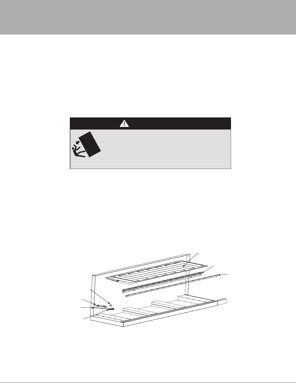
Table of Contents
NOTE: These instructions include information on how to install multiple 7 Series refrigeration units. For information on
dimensions, speci cations, and installation of single units, please refer to the installation guide included with the appliances.
Parts Included ____________________________________________________________________________________________2
Tools Needed ____________________________________________________________________________________________2
Cutout dimensions ________________________________________________________________________________________3
Speci cations ____________________________________________________________________________________________4
Anti-tip location __________________________________________________________________________________________7
Preparing Units for Installation ______________________________________________________________________________ 8
Installation ______________________________________________________________________________________________10
WARNING
TIP OVER HAZARD
Appliance is top heavy and tips easily when not completely
installed. Keep doors closed until appliance is completely installed
and secured per installation instructions.
Use two or more people to move and install appliance. Failure to do
so can result in death or serious injury.
Parts included Tools Needed
Heater (1)
Center Trim Brackets (2)
Center Trim (1)
Top Connecting Plate (1)
Rear Connecting Plate (1)
1/4”-20 x 3/4” Connecting Plate Fasteners (6)
#8-18 x 1/2” Heater Fasteners (3)
8-18 x 1/2” Heater Fasteners (Item 7)
Rear Connecting Plate (Item 5)
Top Connecting Plate (Item 4)
1/4”-20 x 3/4” Connecting Plate
Fasteners (Item 6)
Drill (Not to be used on the leveling feet)
Drill Bits - 3” Phillips (PH2), Torx (T15 & T20)
1/4” & 5/16” Hex Drive
Rubber Mallet
3/8” Wrench
1/8” Allen Wrench
Heater (Item 1)
Center Trim Brackets (Item 2)
Center Trim (Item 3)
2
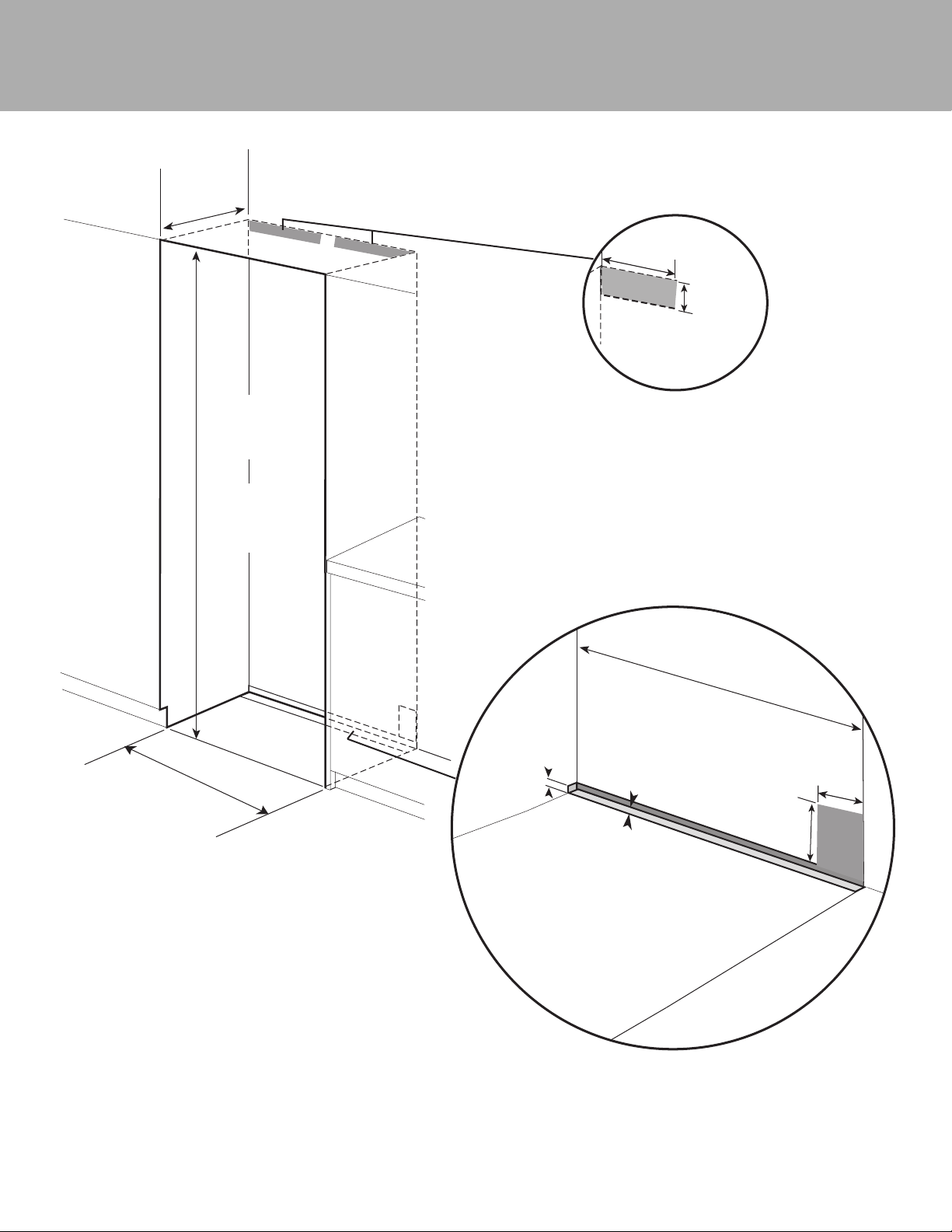
Cutout Dimensions
*
25”
(63.5 cm)
84”
(213.4 cm) min.
opening height
85-3/16”
(216.3cm) max.
opening height
Can be located on either side
Electric Outlet Location
15-1/2”
(39.4 cm)
4-1/4”
(10.8 cm)
+
leveling
dimension
Water Line Entry Area
*Refer to Specification
chart for
specific Models
*Note: For all models, 3” back from the front of the cabinet
on both sides needs to be nished like the outside of the
cabinets
5/8”
(1.6 cm)
1/2”
(1.3 cm)
*Cutout
Width
6”
(15.2 cm)
3”
(7.6 cm)
3
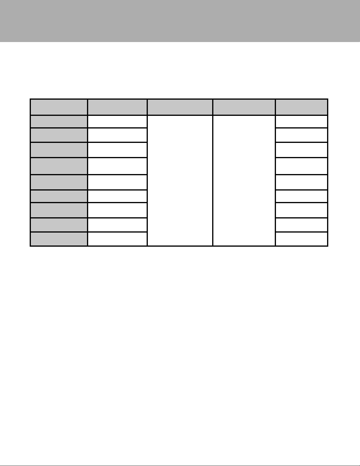
Speci cations
Refer to Installation Guides included with unit for individual dimensions.
Below is a common install chart for reference.
Size Combination Cabinet Cutout Width
18” W / 24”W Models 42” (106.7 cm)
18” W / 30”W Models 48” (121.9 cm) TKK748SS
18” W / 36”W Models 54” (137.2 cm) TKK754SS
24” W / 24”W Models 48” (121.9 cm) TKK748SS
24” W / 30”W Models 54” (137.2 cm)” TKK754SS
24” W / 36”W Models 60” (152.4 cm) TKK760SS
30” W / 30”W Models 60” (152.4 cm) TKK760SS
30” W / 36”W Models 66” (167.6 cm) TKK766SS
36” W / 36”W Models 72” (182.9 cm) TKK772SS
For muti-unit installation, add the width of the units together for cabinet cutout width.
For example: 18” + 24” + 24” = 66” W.
Cabinet Cutout Height
(same for all)
84” (213.4 cm) min
85-3/16” (216.3 cm) max
Cabinet Cutout Depth
(same for all)
25”
(63.5 cm)
Optional
Kickplate
TKK742SS
4
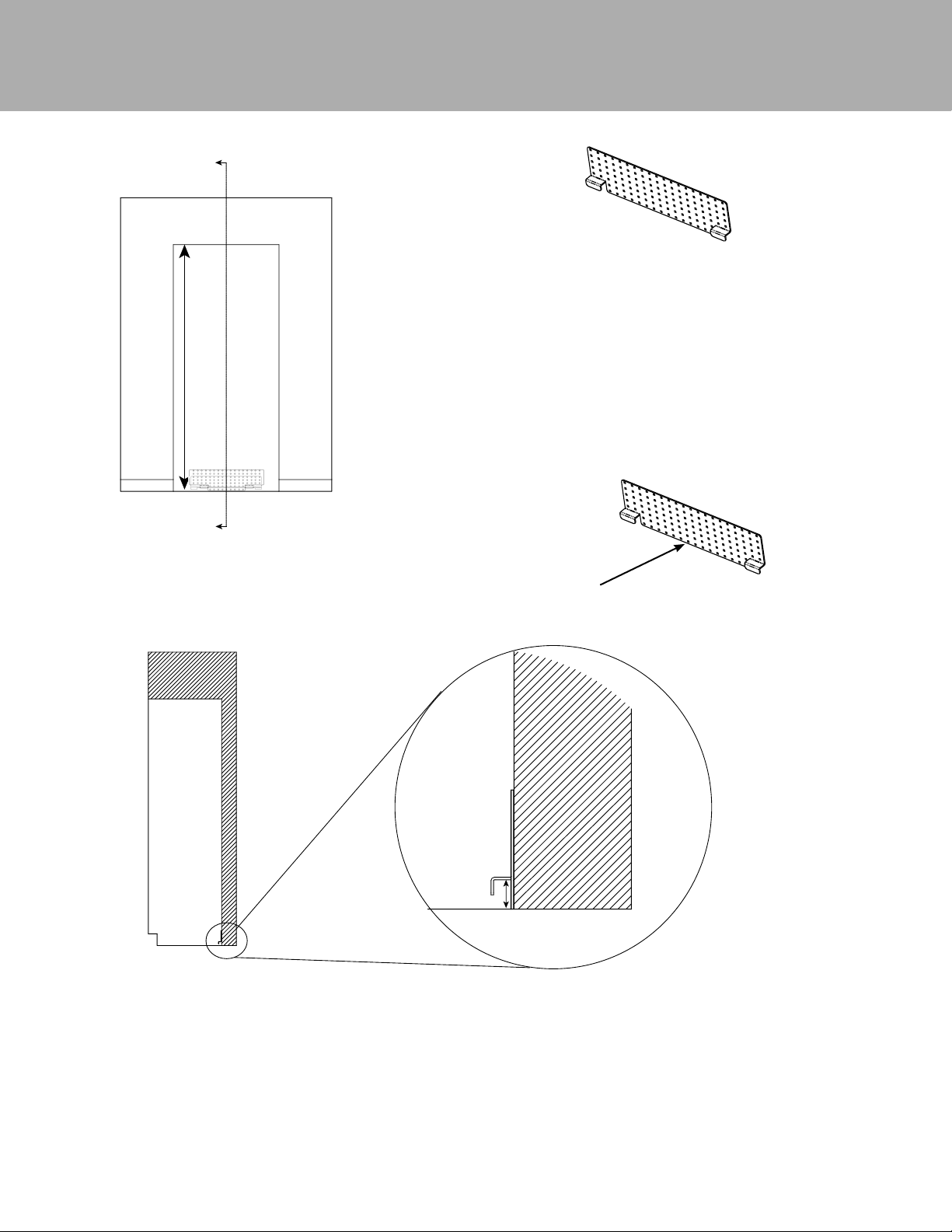
Anti-tip Location
C
Cabinet
Opening
C
Anti-tip Bracket
The anti-tip bracket has several holes set up on a grid in order to better
locate a wall stud. At least 4 places must be used. Anti-tip Bracket must
be centered in cutout - side to side.
NOTE: Number and type of fasteners must be suitable in order to
prevent tipping. For example: use wood screws into wall studs or
masonry anchors if attaching to stone, brick or concrete.
If a wall stud can not be found or when
installing the 18” model, use the lower
section of the bracket and mount to the
base board
Cabinet
Floor
Dimension A = Cabinet opening minus the refrigerator height + 1-1/4" (3.2 cm)
Ex. - Cabinet opening height - 85”
Minimum refrigerator height (sitting on rollers) - 83 15/16”
A = 85” - 83-15/16” +1-1/4” = 2-5/16”
A
5
Rear
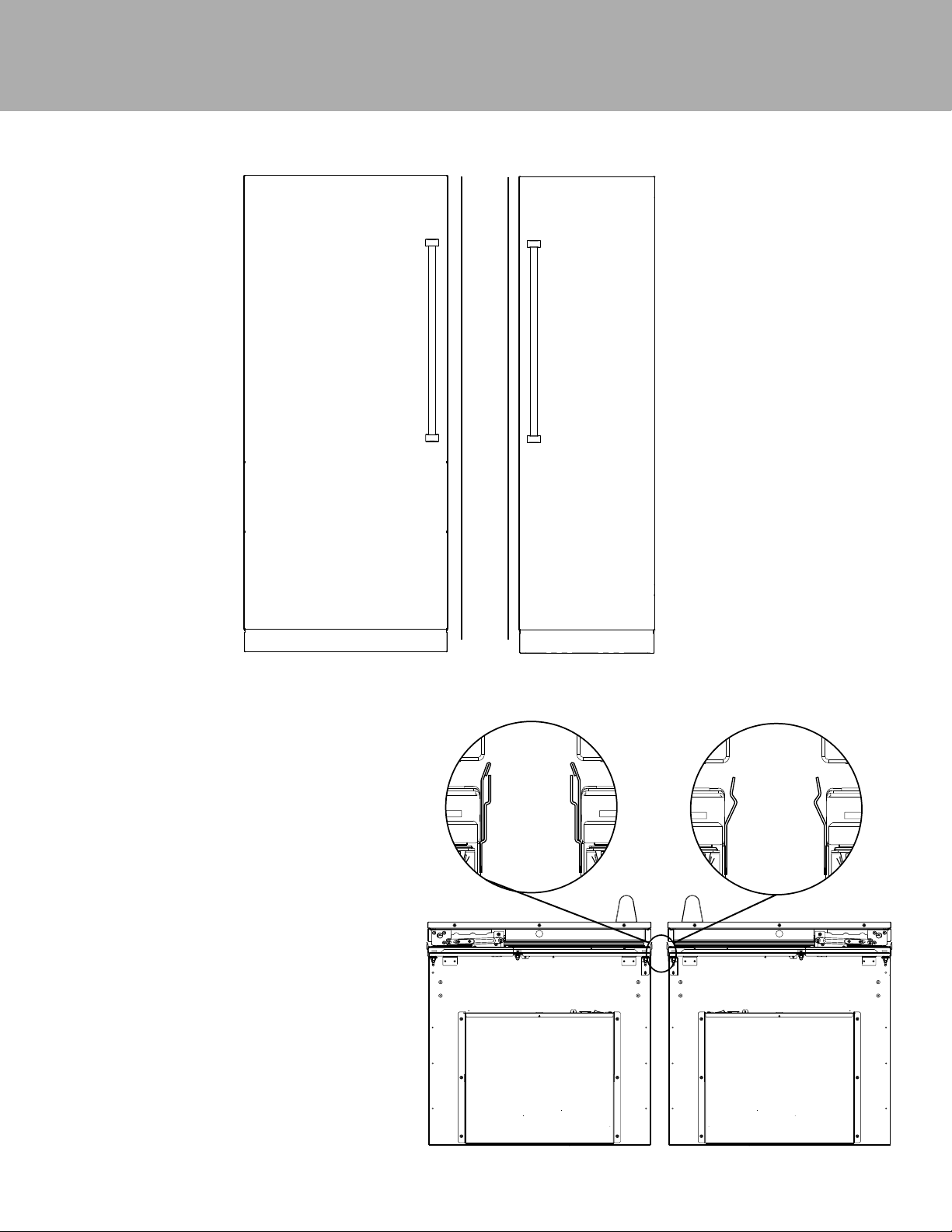
Preparing Units for Installation
Before removing units from pallet, remove the side trim from each unit, install center trim brackets and connection heater (steps 1
thru 4). Make sure units are unplugged and powered o .
A
A
Look closely at the trim already installed on the unit.
If the trim resembles that in Trim A, it will need to be
removed and replaced with Trim B. If the trim already
resembles Trim B, leave as is.
REMOVE TRIM A
INSTALL TRIM B
6
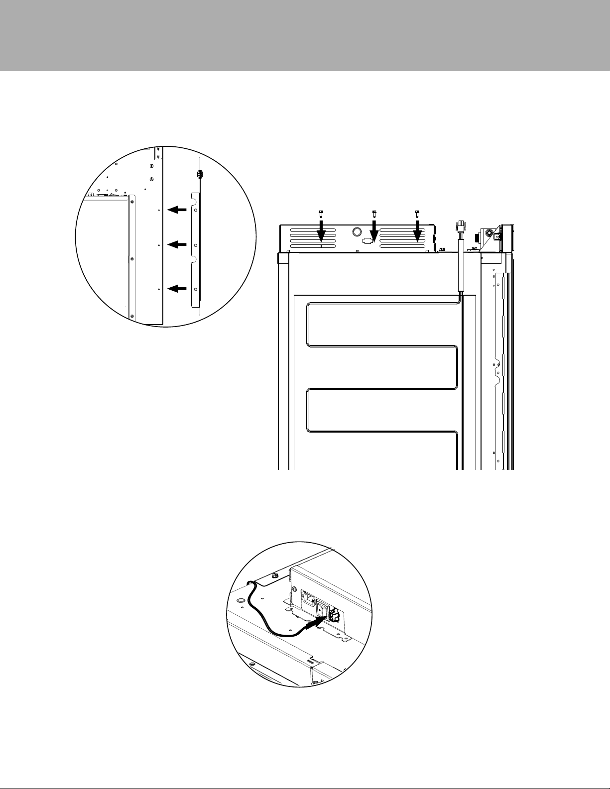
Preparing Units for Installation
3. Fasten heater (Item #1) to the three mounting holes on top of the right hand unit using the #8-18 x 1/2” fasteners (Item #7)
provided.
4. Plug heater terminal into right hand unit using the plug located next to the unit on/o switch.
7
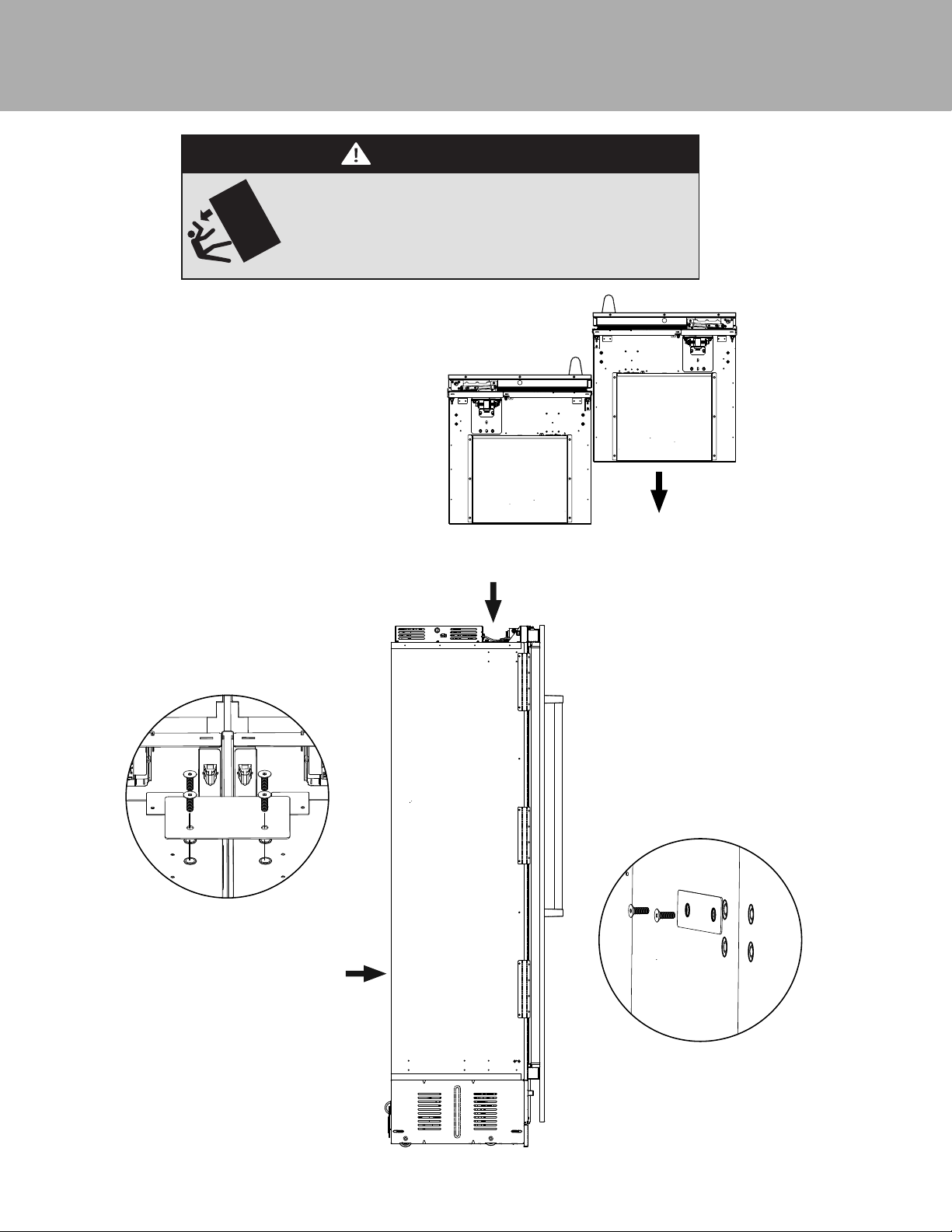
Installation
Appliance is top heavy and tips easily when not completely
installed. Keep doors closed until appliance is completely installed
and secured per installation instructions.
Use two or more people to move and install appliance. Failure to do
so can result in death or serious injury.
5. Remove units from pallets and position together
outside of the cabinet so that top connecting plate
(Item #4) can be installed. If installing on uneven
surfaces, use unit leveling feet to adjust units to that
they are at the same height.
WARNING
TIP OVER HAZARD
6. Install top connecting plate to the threaded
mounting holes provided on the top of the
cabinet using the 1/4”-20 x 3/4” (Item #6)
fasteners. DO NOT install using a drill. Use
manual allen wrench. (See Illustration A)
A.
B.
A.
7. Fasten rear connecting plate (Item #5) to the
threaded mounting holes provided on the
rear of the unit using the 1/4”-20 x 3/4” (Item
#6) fasteners. DO NOT install using a drill.
Use manual allen wrench. (See Illustration B).
Loosely attach the bracket allowing it to pivot.
Tightening the screws will result in the bracket
bending and causing misalignment of the rear
of the units.
Note: *If one or both units have (4)
screw holes, attach using the top
two holes.
B.
*
8
 Loading...