

Viking VEDO 273 Service Notebook
SERVICE NOTEBOOK
ELECTRIC WALL OVEN
VEDO 273
VIKING RANGE CORPORATION, P. O. DRAWER 956, GREENWOOD, MS. 38930 - USA

TABLE OF CONTENTS
Important Information.................................... 4
Important Safety Information........................ 5
All Appliances......................................... 5
Self-Cleaning Oven................................. 5
Oven.......................................................... 5
In Case of Fire............................................ 5
Precautions................................................... 5
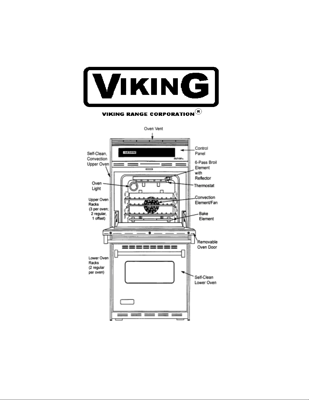
General Information
Oven Operation--
(Not all models are convection equipped.... 6
Baking Guide.............................................. 6
Prepare to Bake.......................................... 6
Remove Items Stored in Oven................... 7
Oven Racks................................................ 7
Oven Rack Placement................................ 7
Bake Pan Placement.................................. 7
Convection Pan Placement........................ 7
Remove Oven Door.................................. 8
Replacing Oven Light............................... 8
Care and Cleaning
Cleaning Parts........................................... 9
Component Testing Information.................... 10
Testing Procedures
Upper and Lower Limit Control, Limit,
Fan Switch................................................. 11
Oven Temperature Sensor......................... 11
Blower Motor............................................ 11
Auto Latch Motor..................................... 12
Convection Fan Motor.............................. 12
Convection Element Testing..................... 12
Broil Element Testing............................... 12
Bake Element Testing............................... 12
Disassembly Procedures
Removing and Replacing Oven................ 13
Control Panel Assembly........................... 13
Electronic Range Control (ERC).............. 13
Mylar Control Panel................................. 13
Transformer/Relay Board(s)..................... 13
Upper Oven High Limit, Thermal Fan,
Vent High Limit Switches......................... 14
Lower Oven High Limit and Thermal
Fan Switch................................................ 14
Oven Sensor.............................................. 14
Bake Element............................................ 14
Broil Element............................................ 15
Broil Element/Broil Element Reflector.... 15
Convection Heating Element.................... 15
Convection Fan Blade................................... 15
Convection Fan Motor.............................. 15
Upper Oven Door latch/Door Plunger
Light Switch Assembly............................. 15
Lower Oven Doo r Latch/Door Plunger
Light Switch Assembly............................. 15
Oven Light Bulb/Oven Light Socket........ 16
Oven Tank Removal ................................ 16
Oven Door Removal................................. 16
Oven Door Assembly............................... 16
Oven Door Hinges.................................... 17
Blower Motor........................................... 17
Vent Assembly/Smoke Eliminator........... 17
Door Assembly (Exploded View)............ 18
Installation
Packing Material....................................… 19
Oven Location.......................................... 19
Cabinet Opening Double Wall Oven........ 19
Electrical Supply Location....................... 19
Electrical Connection Requirements........ 19
Electrical Connection................................ 20
Place Oven in Wall................................... 20
Removal and Replacement of Oven......... 20
Programming Instructions
Electronic Oven Control Options............. 21
Special Oven Control Functions............... 21
Quick Reference Instructions................... 22
Flashing Display....................................... 23
Setting Electronic Clock........................... 23
Setting Electronic Timer........................... 23
Baking, Convection, or Convection Baking 23
Timed Baking, Convection, or
Convection Baking................................... 23
Delayed Baking, Convection, or
Convection Baking................................... 24
Prepare for Broiling.................................. 24
Broiling or Convection Broiling............... 24
Hold.......................................................... 24
Delayed Slow Baking............................... 25
Defrost...................................................... 25
Dehydration.............................................. 25
Prepare for Self-Clean and
Delayed Self-Clean Cycle......................... 26
Self-Cleaning............................................. 26
Delayed Self-Clean Cycle......................... 26
Adjusting Oven Temperature.................... 26
Service Tones and Codes........................... 26
2

TABLE OF CONTENTS (Continued)
Testing Procedures
Service Information....................................... 27
Quick Test Procedure................................... 27
ERC Warning and Failure Codes................. 27
Temperature Calibration Offset................... 28
Function Switch Connection........................ 28
Check Procedures......................................... 28
Transformer/Relay Board 1 ......................... 28
Double Line Break K6.................................. 28
Bake Relay K4.............................................. 28
Broil Relay K5............................................... 28
Convection Element Relay K2...................... 28
Convection Fan Relay K1............................ 28
Oven Light Relay K10................................. 29
Door Lock Relay K3................................... 29
Display (Filament) Voltage........................... 29
Relay Board 2................................................ 29
Double Line Break K1.................................. 29
Bake Relay K2.............................................. 29
Broil Relay K3.............................................. 29
Door Lock Relay K4..................................... 29
Component Testing Information....................30 Thru 33
Wiring Diagram........................................... 34
3
IMPORTANT INFORMATION
Pride and workmanship go into every product to provide our customers with quality products. It is possible,
however, that during its lifetime a product may require service. Products should be serviced only by a
qualified service technician wh o is familiar with the safety procedures required in the repair and who is
equipped with t he proper tools, parts, te sting i nstrume nts and t he a ppr opr iat e s er vic e m an ual . REVIEW ALL
SERVICE INFORMATION IN THE APPROPRIATE SERVICE MANUAL and TECHNICAL
SHEETS BEFORE BEGINNING REPAIRS.
Important Notice for Consumers and Services
WARNING
To avoid risk of serious injury or death, repairs should not be attempted by an unauthorized personnel,
dangerous conditions (such as exposure to electrical shock) may result.
CAUTION
VIKING will not be responsible for any injury or property damage from improper service
procedures. If performing service on your own product, assume responsibility for any personal
injury or property damage which may result.
To locate an authorized servicer, consult the dealer from whom you purchased this product. For
further assistance, call:
Viking Preferred Service
Phone # 601-451-4133
Address your written correspondence to: Viking Preferred Service
111 Front Street
P. O. Drawer 956
Greenwood, MS. 38935-0956
Recognize Safety Symbols, Words, and Labels
Danger-Immediate hazards which WILL result in severe personal injury or death
Warning-Hazards or unsafe practices which COULD result in severe personal injury
or death
CAUTION-Hazards or unsafe practices which COULD result in minor personal injury
or product or property damage.
4
Important Safety Information
To avoid personal injury , do n ot
sit or stand or lean on oven door.
To avoid risk of elect rica l sh ock ,
personal injury, or death, make
sure your oven has been
properly grounded and always
disconnect it from main power supply before any
servicing.
This appliance contains or
produces a chemical or
chemicals which can cause
death or serious illness and w hich a re know n
to the state of California to cause c ance r, bi rth defe cts
or other reproductive harm .. To reduce th e risk f rom
substances in the fu el or f rom fuel combustion make
sure this appliance is installed, operated, and
maintained according to the instructions in this
booklet.
ALL APPLIANCES
1. Proper installation - Be sure your appliance is
properly installed and grounded by a qualified
technician.
2. Never use appliance for warming or heating the
room.
3. Do not leave Children alone - Children should not
be alone or unattended in the area where the
appliance is in use. They should never be allowed
to sit or stand on any part of the appliance.
4. Wear proper apparel - loose fitting or hanging
garments should never be worn while using
appliance.
5. User servicing - Do not repair or replace any part of
the appliance unless specifically recommended in
the manual. All other servicing should be referred
to a qualified technician.
6. Storage in or on appliance - Flammable materials
should not be stored in oven.
7. Do not use water on gre ase fir es - smothe r fire s or
flame, or use dry chemical or foam-type
extinguisher.
8. Use only dry potholders - mois t or dam p potholders
on hot surfaces may result in burns f rom st eam. Do
not let potholders touch burners. Do not use a t owe l
or other bulky cloth.
SELF - CLEANING OVEN
1. Do not clean door gasket. The door gasket is
essential for a good seal. Care should be taken not
to rub, damage, or move the gasket.
2. Do not use oven cleaners. No commercial oven
cleaner or oven liner protective coating of any ki nd
should be used in or around any part of the liner.
3. Clean only parts listed in manual. See CLEANING
section.
4. Before self-cleaning the oven, remove broiler pan,
oven racks, and other utensils.
Oven
1. Use care when opening door, let hot air or steam
escape before removing or replacing food.
2. Do not heat unopened food containers, build-up of
pressure may cause container to burst and result in
injury.
3. Keep oven vent ducts unobstructed.
4. Placement of oven racks. Always place racks in
desired location while oven is cool. If rack is
removed while oven is hot, do not let potholder
contact hot oven.
In Case of Fire
Fires can occur as a result of over cooking or exces sive
grease. Though a fire is unlikely, if one occurs,
proceed as follows:
Oven Fires
1. If you see smoke from oven, do not open oven door.
2. Turn oven control to OFF.
3. As an added precaution, turn off power at main
circuit breaker or fuse box.
4. Turn on vent to remove smoke.
5. Allow food or grease to burn itself out in oven.
6. If smoke and fire persist, call fire department.
7. If there is any damage to components, call repair
service before using oven.
Precautions
• Do not mix household cleaning products. Chemical
mixtures may interact with objectionable or even
hazardous results.
• Do not put plastic items on warm cooking areas.
They may stick and melt.
• Do not use damp sponge or dishcl oth t o clean ov en
when oven is hot. Steam from sponge or dishcloth
can burn.
• Do not leave fat heating unless you remain nearby.
Fat can ignite if overheated by spilling onto hot
surfaces.
5
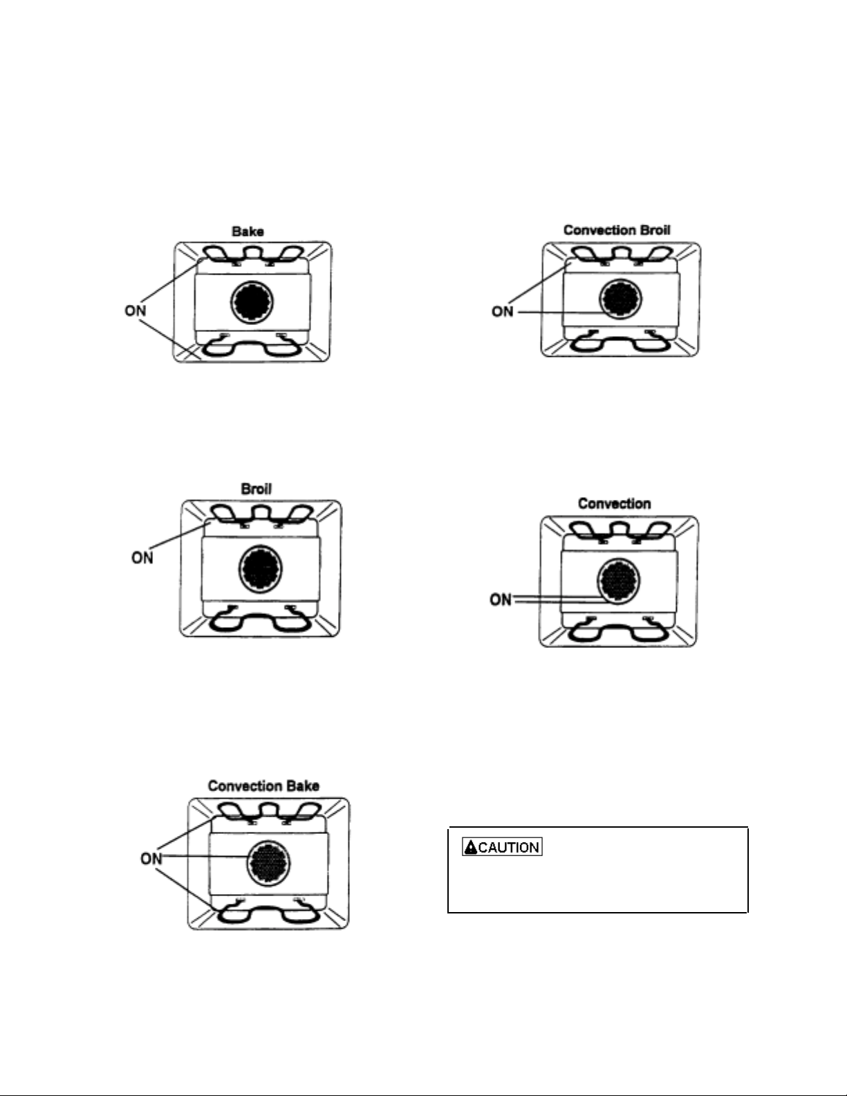
GENERAL INFORMATION
Oven Operation - (not all models are convection
equipped)
Bake
Top and bottom elements operate during bake. Bake
can be used to cook foods which are normally baked.
Oven must be preheated.
Convection Broil
Top elements and fan operate when using convection
broil. Convection broil can be used to cook foods that
are normally broil ed. Oven does not requ ire prehe ati ng
when usi ng convect ion broil. Food does n ot need to be
turned during broiling. Cooks approximately 25%
quicker than broil.
Broil
Top element operates durin g broil. Broil can be use d to
cook foods which are normally broiled. Preheating is
not required when using broil. All foods should be
turned at least once except fish, w hich does not need to
be turned.
Convection Bake
Upper element, lower element, and fan operate during
convection bake. Convection bake should be used for
cooking casseroles and roastin g meats. Oven sh ould be
preheated for best results w hen usin g conv ection bake.
Pans do not need to be staggered. Cooks approximatel y
25% quicker than bake.
Convection
Rear element and fan operate during convection.
Convection should be used for cooking pastries,
souffles, yeast bread, cakes and cook ies. Ov en s h ou ld
be preheated for best results when using convection.
Pans do not need to be staggered. Cooks approximatel y
25% quicker than bake.
Baking Guide
Refer to owners manual, for following
recommendations only as a guide for times and
temperature. Times, rack position, and
temperatures m ay vary depending on conditions
and food type. For best results, alway s ch eck food
at minimum time. When roasting, choose rack
position based on size of food item.
Prepare to Bake
To reduce risk of food poisoning
due to bacterial growth and pro duction of toxins, never hold
meat, milk, fish or eggs for more
than 2 hours before baking.
6
GENERAL INFORMATION
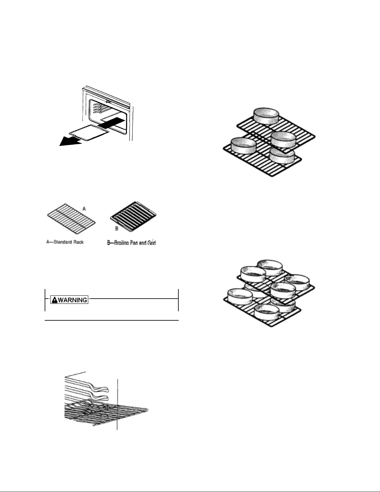
Remove Items Stored in Oven
Remove any pans and ot her co o king ute nsils st or ed i n
oven.
Oven Racks
Use Standard rack for normal baking and broiling.
Oven Rack Placement
Position oven rack before turning oven on.
To avoid damaging oven liner or
creating fire, do not line oven bottom
or racks with foil.
1. Pull rack forward to stop position.
2. Raise front edge of rack and pull until rack is out of oven.
3. Place rack in new rack position.
• Curved edge of rack must be toward rear of oven.
Bake Pan Placement
• Keep pans and baking sheets 2 inches from oven walls.
• Stagger pans placed on different racks so one is not
directly over the other.
Convection Pan Placement
Baking pans and cookie sheets should not touch side or rear
walls of oven. If pans are placed on different racks, they can
be placed directly over each other. Convection baking
circulates air around oven providing even browning on all
rack positions. When using convection, oven can be loaded
on all racks with excellent baking results.
7
GENERAL INFORMATION
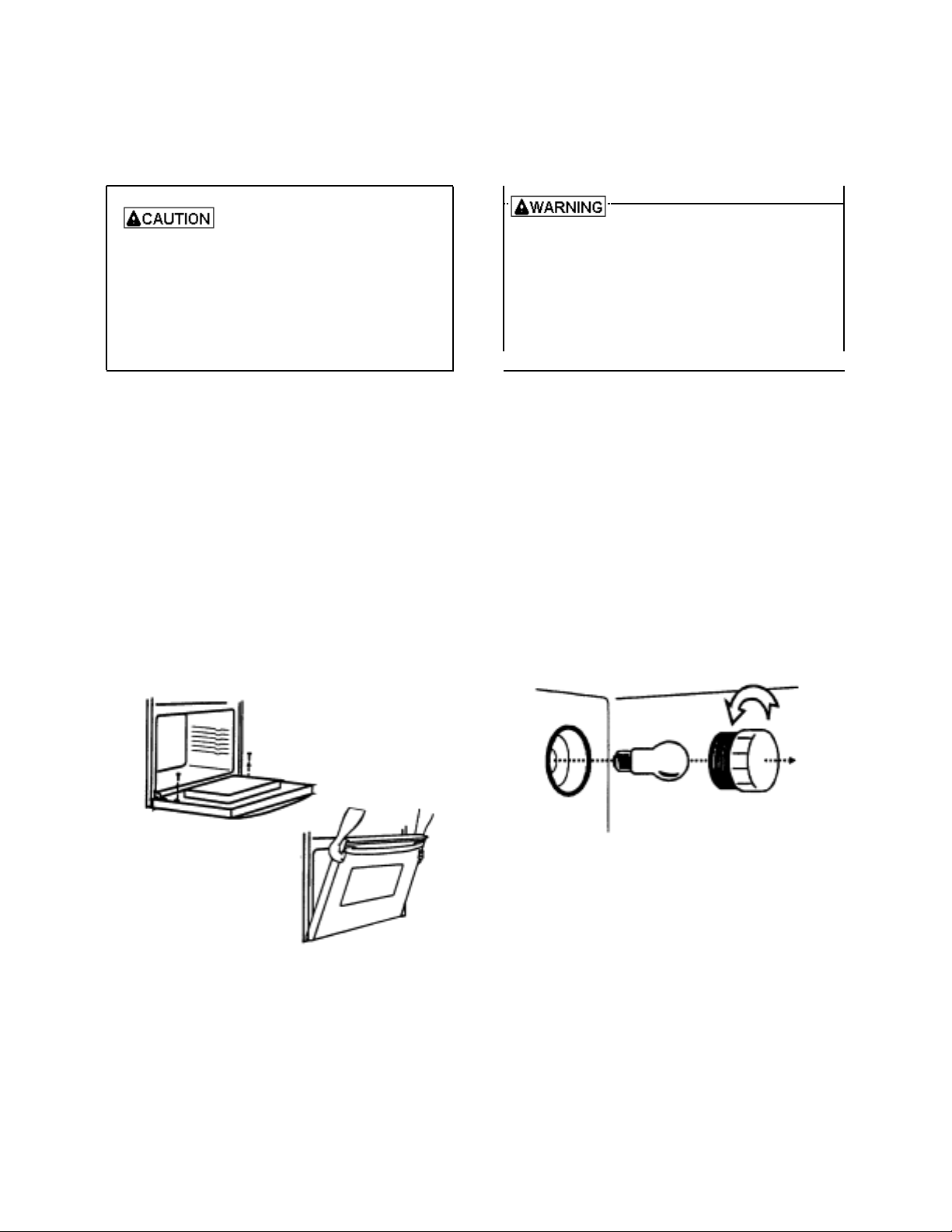
Removing Oven Door
To avoid personal injury or property
damage, handle ov en door w ith care .
• Door is heavy and can be damaged if dropped.
• Avoid placing hands in hinge area when door is
removed. Hinge c an snap closed and pi nch hands.
• Do not scratch or chip glass, or twist door.
Glass may break suddenly.
• Replace door glass if damaged.
• Do not lift door by handle.
1. Open door fully.
2. Remove screws .
• Oven doors are attached with a screw on each
side of oven door.
3. Close door to first stop, grasp door firmly on each
side and lift upward until door is off hinges.
• Do not lift door by handle, glass or handle can
break.
• Only push hinges closed once oven door is
removed if necessary. Use both hands when
closing hinge. Hinge snaps closed.
Replacing Oven light
To avoid risk of burns or electrical
shock, disconnect electrical supply to oven
before cha nging light bulb.
• Before repla cing light bulb make sure bulb and
lens are cool.
• Wear protective gloves.
• Do not operate oven without bulb and lens cov er
in place.
1. Disconnect electrical supply.
2. Remove oven door if desired.
3. Unscrew light bulb cover (counterclockwise) located
in rear of oven cavity. Then turn light bulb
counterclockwise to remove.
4. Replace light bulb with 120 volt, 40 watt appliance
bulb.
• Do not over tighten bulb or cover. They may be
difficult to remove later.
5. Replace light bulb cover and oven door before use.
6. Reconnect power supply.
8
CARE AND CLEANING
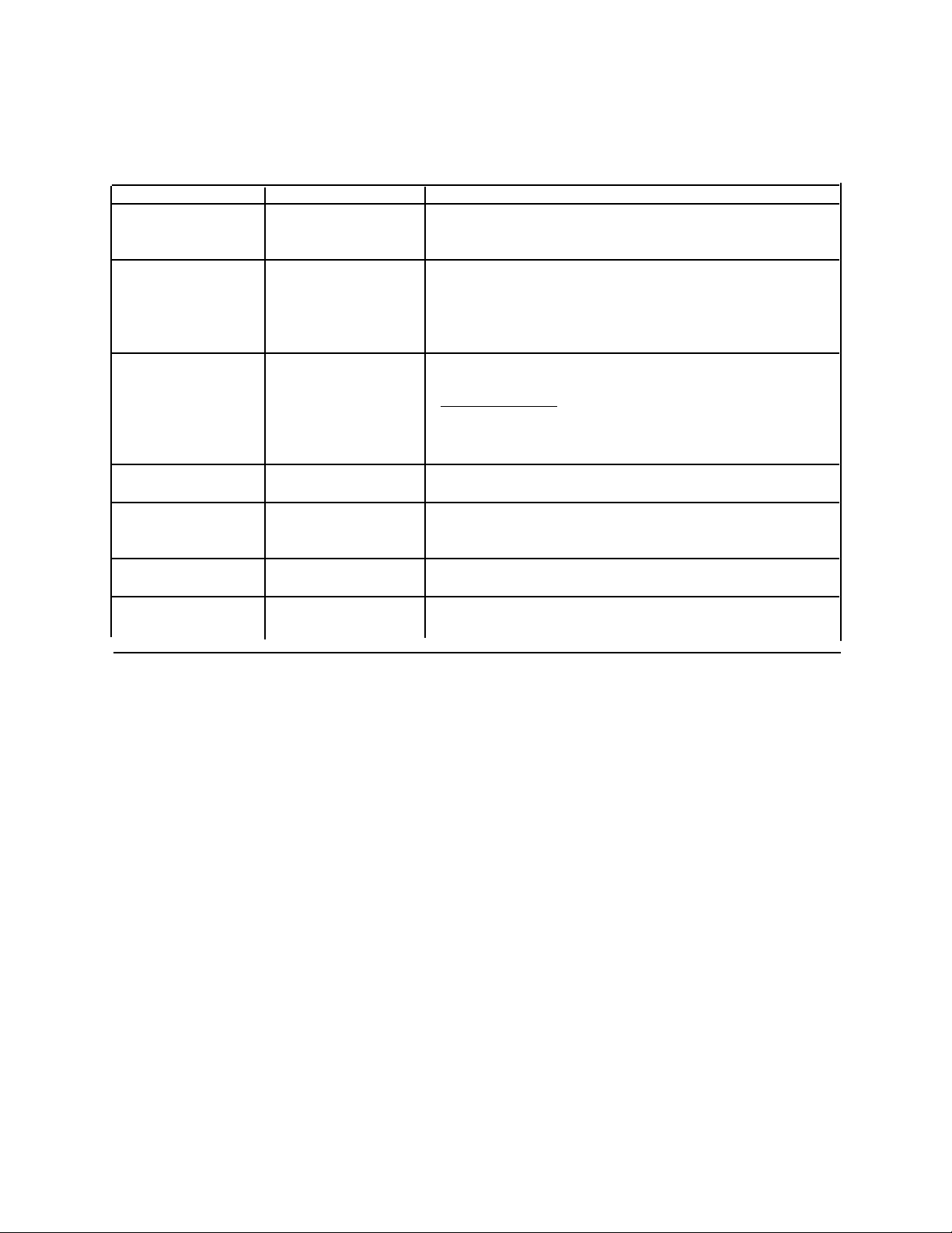
Cleaning Oven Parts
Part Material to Use General Directions
Heating elements Do not clean. Any food on element will burn off.
Broiler pan and grid Soap and a non- Drain fat, cool pan and grid slightly. (Do not let soiled pan and
abrasive plastic grid stand in oven to cool.) Sprinkle with soap. Fill the pan
scouring pad. with warm water. Let pan and grid stand for a few minutes.
Wash or scour if necessary. Rinse and dry. The broiler pan
and grid may also be cleaned in the dishwasher.
Inside oven door Soap and water Clean the outside of the door and the window area with warm
soapy water.
Oven Door Gasket
Do not clean the braided oven door gasket. Gasket should not
be moved while cleaning. Avoid getting any cleaning material
on gasket.
Outside finish Soap and water Wash all glass with cloth dampened in soapy water. Rinse and
polish with a dry cloth.
Oven interior Soap and water Cool before cleaning. Frequent wiping with m ild soap and w ater
surfaces prolongs time between self - cleanings. Be sure to rinse
thoroughly. Clean excess spills b efore self - cleaning.
Control panel Soap and water Wash with cloth dampened in soapy water. Rinse and polish
with a dry cloth.
Oven racks Soap and water For heavy soil, cle an by hand and rinse racks thoroughly for
ease in cleaning. Be sure racks are dry before replacing.
9
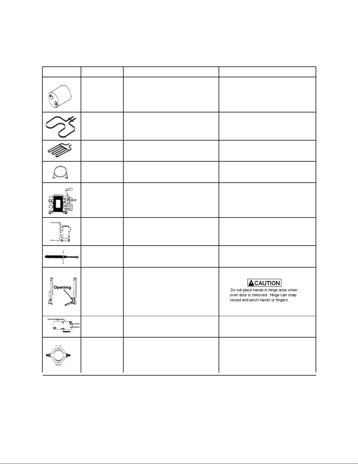
COMPONENT TESTING INFORMATION
To avoid risk of electrical shock, per sonal injur y, or death, discon nect power to oven befor e servicing, u nless tes ting
requires it.
Illustration Component Test Procedure Results
Oven light socket Test continuity of receptacle terminals. Indicates continuity with bulb screwed in.
Measure voltage at oven light. 120 VAC, see wiring diagram for terminal
identification.
If no voltage is present at oven light,
check wiring.
Bake element Disconnect wire terminals and test
voltage to terminals. 240 VAC
Test continuity of element. Indicates continuity.
Broil element Disconnect wire terminals and test
voltage to terminals. 240 VAC
Test continuity of element. Indicates continuity.
Convection Disconnect wire terminals and test
element voltage to terminals. 240 VAC
Test continuity of element Indicates continuity
Convection Verify supply voltage. 120 VAC
motor Disconnect wiring and check Continuity at wire terminals.
fan continuity of motor at the terminals, No continuity from wire terminals to
and verify terminals are not shorted chassis.
to chassis.
Blower motor Verify supply voltage. 120 VAC
Disconnect wiring and check continuity Continuity at terminals.
of motor at the terminals, and verify No continuity from wire terminals to
terminals are not shorted to chassis. chassis.
Heraeus sensor Measure resistance Approximately 1100Ώ at room
temperature 75°F.
Hinge Carefully open the hinge fully, and
insert a wooden dowel or screwdriver
bit into opening. Remove top and
bottom screws securing hinge. Slide
hinge top toward rear of unit and guide
hinge out through frame opening or
storage drawer.
Door lock Switch connection in following position
switch or Unlocked COM-NO=Open, COM-NC=Closed
light switch Locked / Actuated COM-NO=Closed COM-NC=Open
Controls if Verify proper operation. Normally Open
equipped with: 042045 Control limit upper oven Open at 220°F, Closes at 170°F
042056 Fan switch Open at 120°F, Closes at 150°F
042066 Limit switch Open at 90°F, Closes at 100°F
31852801 Control limit lower oven Open at 240°F, Closes at 210°F
10
TESTING PROCEDURES
To avoid risk of electrical shock, personal
injury, or death, disconnect power to unit
before servicing, unless testing requires it.
Upper and Lower Limit Control, Limit, Fan Switch
Upper limit control 200°F 170°F
Lower limit control 120°F 150°F
Limit switch 90°F 100°F
Fan switch 240°F 210°F
Open Close
1. Turn off power to range.
Control.
Following is approximate resistance:
75°F -- 1082 ohms
350°F -- 1656 ohms
550°F -- 2056 ohms
880°F -- 2686 ohms
Sensor resistance can be checked by removing the
sensor interconnect harness plug from the ERC and
inserting ohmmeter leads into the harness connector
plug. A resistance reading of approximately 1100 ohms
should be indicated at ambient room temperature
(75°F). If a higher resistance is in dicated then remove
sensor from oven, disconnect sensor from harness at
plug, and recheck sensor resistance to assure that the
problem is in the sensor and not in the interconnect
harness or due to a bad connection.
2. Remove oven from wall cutout.
3. Remove screws securing cabinet top shield to outer
cabinet wrapper shield.
4. Disconnect wires from switch terminal conn ecti ons.
5. Attach ohmmeter leads to switch terminals. At
ambient room temperature (70°F.) continuity should
be indicated.
Oven Temperature Test
The following procedures should be used to verif y oven
temperature calibration.
• Verify oven door is adjusted and sealing properly.
• Do not cover the oven racks or oven bottom with
foil.
1. Acquire a 8 1/2x 11 inch piece of aluminum foil.
2. Fold the aluminum foil five times, doubling the
thickness with each fold.
3. After the fifth fold, place the thermocouple tip into
the center of the foil and fold over the
thermocouple. Fold the ends of the foil sides to
NOTE: Sensor resistance will increase if held in your
hand.
1. Disconnect power to oven.
2. Disconnect sensor harness plug from ERC.
3. Connect meter leads into harness connector plug,
resistance should be approximately 1100 ohms at
room temperature 75°F.
• If a higher resistance is indicated remove sensor
from oven. Dis connect sens or from har nes s at th e
plug, recheck sensor resistance to assure the
problem is in the sensor and not in the
interconnecting harness, or due to a bad
connection.
NOTE: Sensor resistance will increase if held in your
hand.
Blower Motor
attach foil to thermocouple.
4. Place the oven rack in the center of the oven cavity.
Position thermocouple on the center of the rack.
5. Turn oven to 350°F and allow to cycle for 25 to 30
minutes. Oven should cycle between 330°F to
370°F.
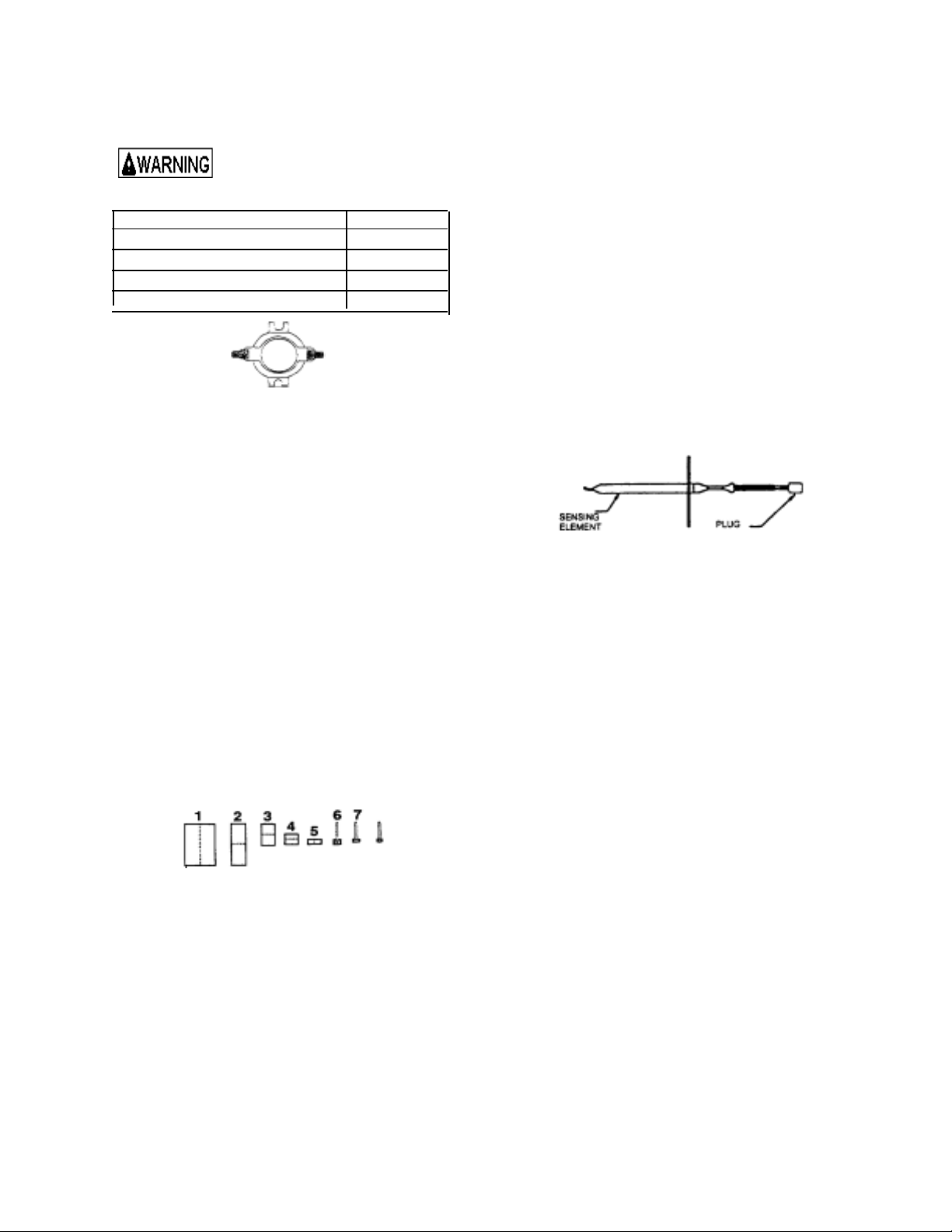
Oven Temperature Sensor
Detail testing can be accomplished as follows: The
oven temperature sensor is mounted in the oven cavity
and electrically connected to the Electronic Range
Fan may come on at any time to cool components.
1. Turn off power to oven.
2. Remove oven from wall cutout.
3. Remove screws securing outer cabinet top shield to
outer cabinet wrapper shield.
4. Disconnect wires from motor terminal connectors.
5. Attach ohmmeter leads to terminal tabs on motor.
6. A resistance of ohms should be indicated but may
vary with each motor tested. This test is to check
the motor winding fo r a n o p en o r shor te d winding.
If zero or infinite ohms is indicated, the motor
11
 Loading...