

Viking VE-ARSW Product Manual
Designed, Manufactured and Supported in the USA
VIKING
COMMUNICATION & SECURITY SOLUTIONS
PRODUCT MANUAL
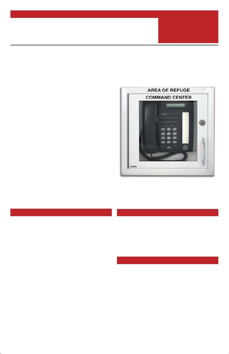
Area of Refuge Surface Mount
Command Center Cabinet
Each Area of Refuge is required to have a
central control point (Command Center)
where the emergency phones call for assistance.
In low rise buildings (less than 60 ft. tall) the
Command Center can simply be a telephone
mounted in a cabinet located on the ground
floor of the elevator lobby. The VE-ARSW
cabinet is ideal for this application, allowing
you to mount a single line phone or PABX
Key phone.
The VE-ARSW is a 13” x 13.5” x 4” surface
mount metal cabinet with a hinged door,
roller catch, chrome handle, phone mounting
studs and optional lock. The lock is equipped
with a breakaway cam allowing emergency
personnel to force the door open if the key
cannot be found.
Shown with Panasonic 824 PABX key phone
model KX-T7731 (not included)
VE-ARSW
Command Center
Cabinet
December 21, 2016
Features
• 20 gauge galvanneal steel cabinet with
gloss white powder coat finish
• Optional roller catch to keep door closed
when not using the lock
• Lock with breakaway cam and two keys
• Heavy duty chrome plated cast handle
• Mounting studs on back panel for
mounting any standard wall phone
• Hinged door with clear acrylic window
www.vikingelectronics.com
Information: (715) 386-8861
Applications
• Wall mounting an Area of Refuge command center phone at the ground floor elevator lobby in low rise buildings
Specifications
Material: 20 gauge galvanneal steel
Finish: Gloss white powder paint
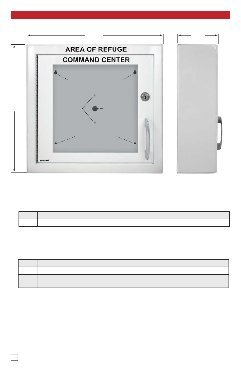
Dimensions: 13” x 13.5” x 4” (330.2mm x
342.9mm x 101.6mm)
Weight: 8.0 lbs (3.63 kg)
Mounting: Surface mount to wall via (4) mounting
holes
Included Hardware: (2) keys, handle with #8-32
x 3/4” mounting screws, roller latch with (2) #8 x
3/8” sheet metal mounting screws
Installation and Specifications
13.5”
13.0”
4.0”
(2) key hole mounting holes
(2) mounting holes
(2) studs for mounting
a standard wall phone
Access hole
for wiring
Front View Side View
A. Installing the Handle
Step 1 Align the handle with the two holes on the outside of the cabinet door.
Step 2 Attach using two 8-32x3/4” screws provided.
B. Installing the Roller Catch
Step 1 Align the roller catch with the two holes centered on the inside of the door.
Step 2 Attach using two #8x3/8” sheet metal screws.
Adjust the roller catch so that it catches the frame of the cabinet when opening and
Step 3
closing.
2
 Loading...