

Page 1
Add Weatherproof Mounting to Your
Viking Phone or
Doorbox
Dimensions: See “Specifications,” page 2
Shipping Weight: VE-9x12 - 5.4 kg (12 lbs), VE-9x20 - 7.3 kg
(16 lbs)
Colors: Red with white lettering or yellow with red lettering
Conduit Opening: ¾” NPT with plug, top and bottom
PPrraaccttiicce
e
T
T
EELLEECCOOM
M
S
S
OOLLUUTTIIOONNSSFFOORRTTHHE
E
221
1
SST
T
C
C
EENNTTUURRY
Y
TECHNICAL
TECHNICAL
SSppeecciiffiiccaattiioonns
s
hhttttpp::////wwwwww..vviikkiinnggeelleeccttrroonniiccss..ccoom
m
PPhhoonnee......771155..338866..8888661
1
iinnffoo@@vviikkiinnggeelleeccttrroonniiccss..ccoom
m
AApppplliiccaattiioonns
s
FFeeaattuurrees
s
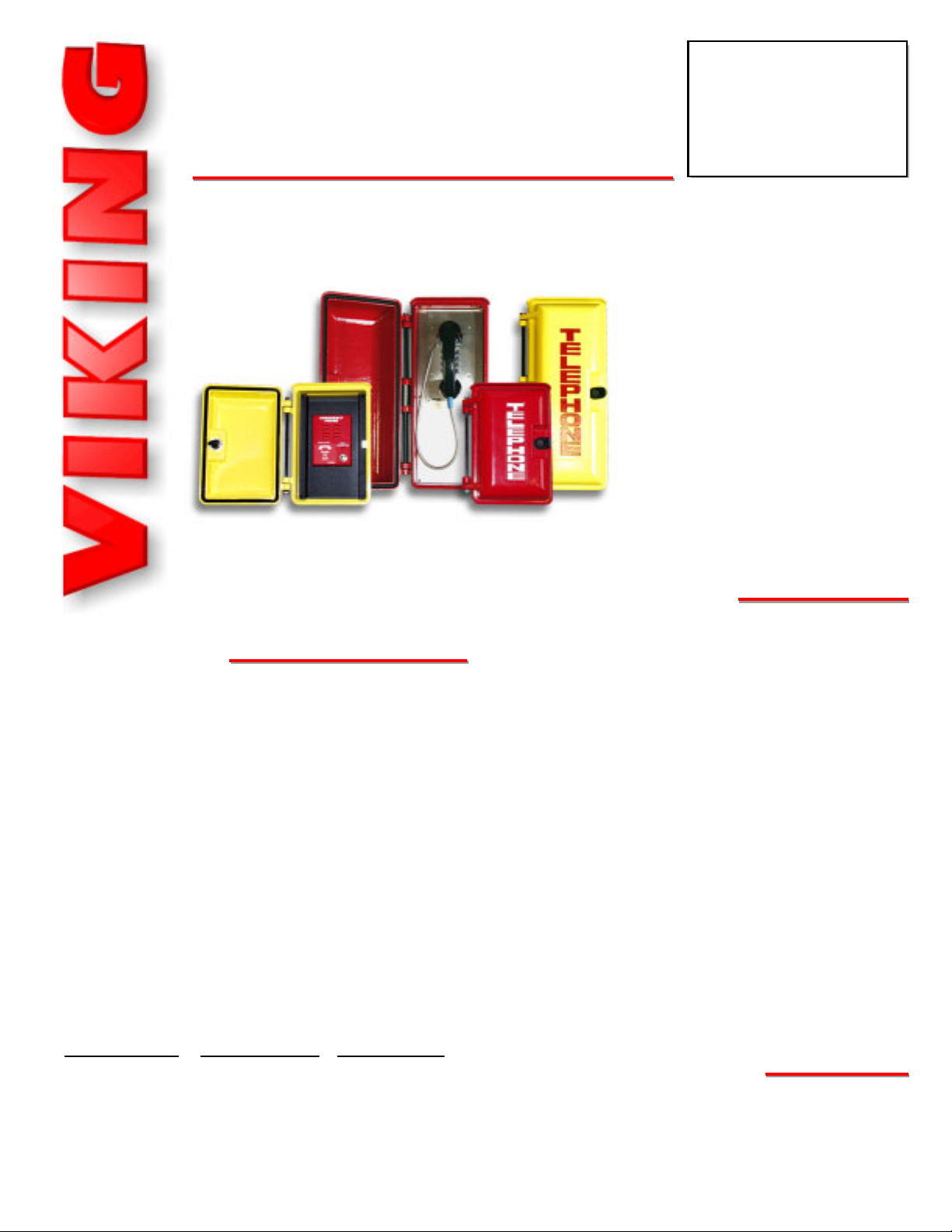
The VE-9x12 and VE-9x20 provide
the ultimate in weather protection for
your Viking product!
These enclosures are constructed of
cast aluminum and are made for
years of outdoor service. The heavyduty aluminum doors are labeled
“Telephone” and have a gasket seal
to keep out even the harshest
weather. The VE-9x12 allows you to
choose from two panels that allow
mounting many different Viking
products.
• Heavy-duty cast aluminum construction
• Gasket sealed door
• Drip guard
• Universal mounting adapter panel
• 3/4” NPT conduit openings on top and bottom
• Available in two colors: safety yellow or emergency red
• Mounting holes for a standard RJ11 wall plate
(VE-9x12 with adapter panel 1)
• Hardware included
• Available with two adapter panels (VE-9x12)
• Optional VE-PBL lock and key set available
• Compatible with these Viking products:
• Parking lots
• Maintenance areas
• Building exteriors
• Swimming pools
• Play grounds
• Roadside help areas
VE-9x12(R/Y)-2
- E-10
- E-15
- E-1600-20A
- E-30
- W-1000
- W-3000
VE-9x12/VE-9x20
VE-9x12/VE-9x20
Weatherproof
Enclosures
March 26, 2002
Both the VE-9x12 and VE-9x20 are
available in two high visibility colors:
safety yellow or emergency red.
VE-9x20(R/Y)
- K-1500-7
- K-1900-7
- K-1900-8
R = Red
Y = Yellow
VE-9x12(R/Y)-1
- E-1600A
- E-1600-03A
- E-1600-45A
- E-20A
- K-1500P-W
- K-1900W-2
- W-2000A
VE-9x12(Y)
(shown with E-1600A)
VE-9x20(R)
(shown with K-1900-8)
VE-9x12(R)
VE-9x20(Y)
Page 2
7.08
0.29
0.29
10.725
11.23
3.70
1.810
3.625
5.615
1.85
0.36 Typ.
3.25
3.625
3.54
3.70
1.81
0.36
1.85
0.25
(4) 6-32
Clinch Nuts
0.08
0.203 Dia.
4 Places
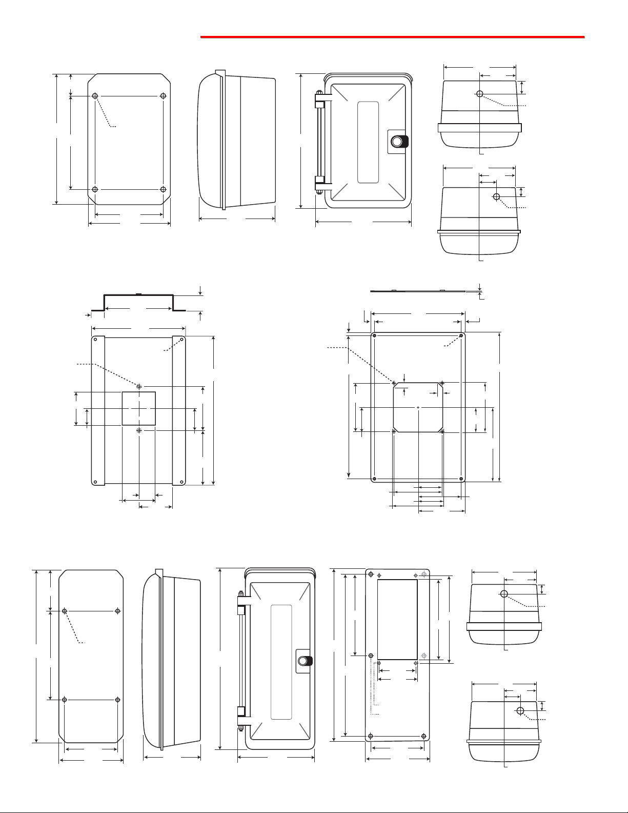
SSppeecciiffiiccaattiioonns
s
7.08
5.48
11.23
3.30
2.50
4.40
1.65
1.25
1.25
2.74
2.50
1.25
0.80
Typ.
(2) 8-32
Clinch Nuts
0.203 Dia.
4 Places
A. VE-9x12 Box
Rear View
Side View
Front View
1. Adapter Panel 1
2. Adapter Panel 2
B. VE-9x12 Adapter Panels
C. VE-9x20 Box
Rear View
Side View
Front View
Adapter Panel
Minimum Internal Clearance: 5.75” x 10.0” x 6.75”
(12 gauge Aluminum Black Powder Paint)
Minimum Internal Clearance: 5.75” x 10.0” x 5.25”
(12 gauge Aluminum Black Powder Paint)
Minimum Internal Clearance: 5.75” x 10.0” x 4.0”
Minimum Internal Clearance: 5.75” x 17.25” x 6.75”
(14 gauge Stainless Steel)
Minimum Internal Clearance: 5.75” x 17.25” x 4.0”
Top View
Bottom View
Top View
Bottom View
1.60
7.10
3.55
1.25
11.25
8.0
(4) .43 Dia.
5.87
7.10
7.45
T
E
L
12.6
E
P
H
O
N
E
9.375
1.625
Center Line
7.10
Center Line
3.55
3/4" Conduit
Knockout
0.875
3/4" Conduit
Knockout
5.0
19.0
8.0
(4) .43 Dia.
5.88
7.19
7.25
20.25
T
E
L
E
P
H
O
N
E
9.25
18.76
18.28
9.14
4.50
4.60
(4) Tapped 6-32
(6) 0.218 Diameter
6.49
7.02
9.50
9.00
7.02
3.51
Center Line
7.02
3.51
1.75
Center Line
0.75
3/4" Conduit
Knockout
0.75
3/4" Conduit
Knockout
Page 3

IInnssttaallllaattiioon
n
K-1900W-2 or K-1500P-W
(not included)
RJ-11 Wall Plate
(not included)
Adapter Panel #1
(included)
VE-9x12 Box
(included)
A. Using the VE-9x12 to mount the K-1900W-2 or K-1500P-W
1. Mount the VE-9x12 to the wall, or surface desired, using the (4) corner mounting holes.
2. Run the conduit and wiring as appropriate.
3. Attach adapter panel #1 using the (4) included 8-32 x 3/8 black cap screws.
4. Attach a standard RJ11 wall plate (Radio Shack part # 279-451 or equivalent).
5. Attach the K-1900W-2 or K-1500P-W to the RJ11 wall plate.
B. Using the VE-9x12 to mount the E-1600A, E-1600-03A, E-1600-45A, W-2000A or E-20A
1. Mount the VE-9x12 to the wall, or surface
desired, using the (4) corner mounting holes.
2. Run the conduit and wiring as appropriate.
3. Attach adapter panel #1 using the (4) includ-
ed 8-32 x 3/8 black cap screws.
4. Attach the Viking product directly to the
adapter using the installation instructions provided in the product’s Technical Practice.
E-1600A Shown
(not included)
Adapter Panel #1
(included)
VE-9x12 Box
(included)
C. Using the VE-9x12 to mount the E-10, E-15, E-1600-20A, E-30, W-1000 or W-3000
1. Mount the VE-9x12 to the wall, or surface
desired, using the (4) corner mounting holes.
2. Run the conduit and wiring as appropriate.
3. Attach adapter panel #2 using the (4) includ-
ed 8-32 x 3/8 black cap screws..
4. Attach the Viking product directly to the
adapter using the installation instructions
provided in the product’s Technical Practice.
W-3000 Shown
(not included)
Adapter Panel #2
(included)
VE-9x12 Box
(included)
(4) 8-32 x 3/8 black cap
screws (included)
(4) 8-32 x 3/8 black cap
screws (included)
(4) 8-32 x 3/8 black cap
screws (included)
Page 4

Due to the dynamic nature of the product design, the information contained in this document is subject to change without notice. Viking Electronics, and its affiliates and/or
subsidiaries assume no responsibility for errors and omissions contained in this information. Revisions of this document or new editions of it may be issued to incorporate
such changes.
Fax Back Doc 413 ZF301480 Rev BPrinted in the U.S.A.
PPrroodduuccttSSuuppppoorrttLLiinnee......771155..338866..8866666
6
FFaaxxBBaacckkLLiinnee......771155..338866..4433445
5
E-10
E-15
E-1600A
E-1600-03A
E-1600-45A
E-20A
E-30
K-1500P-W
K-1500-7
K-1900W-2
K-1900-7
K-1900-8
W-1000
W-2000A
W-3000
Box
VE-9x12
VE-9x12
VE-9x12
VE-9x12
VE-9x12
VE-9x12
VE-9x12
VE-9x12
VE-9x20
VE-9x12
VE-9x20
VE-9x20
VE-9x12
VE-9x12
VE-9x12
Color
R or Y
R or Y
R or Y
R or Y
R or Y
R or Y
R or Y
R or Y
R or Y
R or Y
R or Y
R or Y
R or Y
R or Y
R or Y
Panel
2
2
1
1
1
1
2
1
1
2
1
2
Enclosure Part Number
Product
CCoommppaattiibblleePPrroodduuccttssaannddAAddaapptteerrPPaanneells
s
210
210
215
215
215
210
212
355
352
360
360
362
170
170
180
Emergency speaker phone with call button, flush mount.
Emergency speaker phone, push & hold button, flush mount.
ADA compliant handsfree emergency phone.
ADA compliant handsfree emergency phone.
ADA compliant handsfree emergency phone, yellow.
Emergency speaker phone with push button, surface mount.
Stainless steel handsfree phone with dialer, flush mount.
Wall phone with ringer and network.
Vandal resistant stainless steel panel phone.
Hot-line wall phone with non-volatile memory.
Hot-line vandal resistant stainless steel panel phone.
Hot-line, stainless steel panel phone with keypad and armored cable.
Weather resistant handsfree doorbox, flush mount.
Weather resistant handsfree doorbox, surface mount.
Stainless steel handsfree doorbox, flush mount.
Fax
Back #
Description
Panel Phone
(not included)
Adapter Panel
(included)
VE-9x20 Box
(included)
C. Using the VE-9x20 to mount the K-1500-7, K-1900-7 or K-1900-8
1. Remove adapter panel from the VE-9x20 using
the included hex key.
2. Mount the VE-9x20 to the wall, or surface
desired, using the (4) corner mounting holes.
3. Run the conduit and wiring as appropriate.
4. Attach adapter panel.
5. Attach the Viking product directly to the adapter
panel using the installation instructions provided in the product’s Technical Practice.
Note: If you wish to shorten the armored cable of
the panel phones, you may do so by loosening the
6-32 nut and brass collar located on the back of the
stainless steel panel and pulling the cable through
to its desired length, then retightening the nut and
brass collar (see diagram right).
D. Optional VE-PBL Push Button Lock
An optional VE-PBL lock and key set is available if you choose
to keep your VE-Series phone box locked. Please contact your
distributor or Viking Electronics “Spare Parts” website for pricing and availability.
Important: The lock and key set is only available with one type
of key. Every lock will use the same key.
VE-PBL Lock
Caution: When warm air comes in contact with cold surfaces, such as outside walls and conduits, it causes condensation. To prevent condensation and moisture from accumulating inside the VE-9x20 always bring conduit into the bottom of the unit.
1. 6-32 Nut-
Loosen
2. Brass Collar - Loosen set
screw, using 3/32 hex key
(included)
3. Pull cable to
desired length
(6) 8-32 x 3/8 stainless
steel cap screws (included)
T
E
L
E
P
H
O
N
E
 Loading...