

Viking VCIH56608SM, VCIH56608VC, VCIH56608SB, VCIH56608PG, VCIH56608RE Installation Manual
...
Installation
Professional Indoor & Outdoor Hoods
VWH53012 / VWH53612
VWH53048 / VWH53648 / VWH54248
VWH54848 / VWH56048
VCWH53048 / VCWH53648 / VCWH54248
VCWH54848 / VCWH56048
VCIH53608 / VCIH54208 / VCIH55408 / VCIH56608
VBCV53638 / VBCV54238 / VBCV54838 / VBCV56038 / VBCV56038
VWHO3678 / VWHO4878 / VWHO6078 (Canadian Outdoor models not applicable)

2
Warnings & Important Information
_ _ _ _ _ _ _ _ _ _ _ _ _ _ _ _ _ _ _ _ _ _ _ _ _ _ _ _ _ _ _ _ _ _ _ _ _ _ _ _ _ _ _ _ _ _ _ _ _ _ _ _ _ _ _ _ _ _ _ _ _ _ _ _ _ 3 -
4
VWH/CVWH 10” H/12”H. Wall Hoods w/Standard Ventilator 30”, & 36”
Dimensions & Specifications_ _ _ _ _ _ _ _ _ _ _ _ _ _ _ _ _ _ _ _ _ _ _ _ _ _ _ _ _ _ _ _ _ _ _ _ _ _ _ _ _ _ _ _ _ _ _ _ _ _ _ _ _ _ _ _ _ _ _ _ _ _ _ 5
Clearance Dimensions _ _ _ _ _ _ _ _ _ _ _ _ _ _ _ _ _ _ _ _ _ _ _ _ _ _ _ _ _ _ _ _ _ _ _ _ _ _ _ _ _ _ _ _ _ _ _ _ _ _ _ _ _ _ _ _ _ _ _ _ _ _ _ _ _ _ _ _ _ 6
Interior Ventilator Dimensions _ _ _ _ _ _ _ _ _ _ _ _ _ _ _ _ _ _ _ _ _ _ _ _ _ _ _ _ _ _ _ _ _ _ _ _ _ _ _ _ _ _ _ _ _ _ _ _ _ _ _ _ _ _ _ _ _ _ _ _ 7
VWH/CVWH 18”H. 24”Deep Wall Hoods 30”, 36”, 42”, 48”, & 60”
Dimensions & Specifications _ _ _ _ _ _ _ _ _ _ _ _ _ _ _ _ _ _ _ _ _ _ _ _ _ _ _ _ _ _ _ _ _ _ _ _ _ _ _ _ _ _ _ _ _ _ _ _ _ _ _ _ _ _ _ _ _ _ _ _ _ _ 8
Clearance Dimensions _ _ _ _ _ _ _ _ _ _ _ _ _ _ _ _ _ _ _ _ _ _ _ _ _ _ _ _ _ _ _ _ _ _ _ _ _ _ _ _ _ _ _ _ _ _ _ _ _ _ _ _ _ _ _ _ _ _ _ _ _ _ _ _ _ _ _ _ _ _ _ 9
Interior Ventilator Dimensions _ _ _ _ _ _ _ _ _ _ _ _ _ _ _ _ _ _ _ _ _ _ _ _ _ _ _ _ _ _ _ _ _ _ _ _ _ _ _ _ _ _ _ _ _ _ _ _ _ _ _ _ _ _ _ _ _ _ _ _ _ 1 0
Exterior Ventilator Dimensions _ _ _ _ _ _ _ _ _ _ _ _ _ _ _ _ _ _ _ _ _ _ _ _ _ _ _ _ _ _ _ _ _ _ _ _ _ _ _ _ _ _ _ _ _ _ _ _ _ _ _ _ _ _ _ _ _ _ _ 1 1
VWHO/CVWHO 18”H. Outdoor Wall Hoods 36”, 48”, & 60”
Dimensions & Specifications _ _ _ _ _ _ _ _ _ _ _ _ _ _ _ _ _ _ _ _ _ _ _ _ _ _ _ _ _ _ _ _ _ _ _ _ _ _ _ _ _ _ _ _ _ _ _ _ _ _ _ _ _ _ _ _ _ _ _ _ _ _ 1 2
Clearance Dimensions _ _ _ _ _ _ _ _ _ _ _ _ _ _ _ _ _ _ _ _ _ _ _ _ _ _ _ _ _ _ _ _ _ _ _ _ _ _ _ _ _ _ _ _ _ _ _ _ _ _ _ _ _ _ _ _ _ _ _ _ _ _ _ _ _ _ _ _ 1 3
VCWH/CVCWH Chimney Wall Hoods 30”, 36”, 42”, 48”, & 60”
Dimensions & Specifications _ _ _ _ _ _ _ _ _ _ _ _ _ _ _ _ _ _ _ _ _ _ _ _ _ _ _ _ _ _ _ _ _ _ _ _ _ _ _ _ _ _ _ _ _ _ _ _ _ _ _ _ _ _ _ _ _ _ _ _ _ _ 1 4
Clearance Dimensions _ _ _ _ _ _ _ _ _ _ _ _ _ _ _ _ _ _ _ _ _ _ _ _ _ _ _ _ _ _ _ _ _ _ _ _ _ _ _ _ _ _ _ _ _ _ _ _ _ _ _ _ _ _ _ _ _ _ _ _ _ _ _ _ _ _ _ _ 1 5
Interior Ventilator Dimensions _ _ _ _ _ _ _ _ _ _ _ _ _ _ _ _ _ _ _ _ _ _ _ _ _ _ _ _ _ _ _ _ _ _ _ _ _ _ _ _ _ _ _ _ _ _ _ _ _ _ _ _ _ _ _ _ _ _ _ _ 1 6
Exterior Ventilator Dimensions _ _ _ _ _ _ _ _ _ _ _ _ _ _ _ _ _ _ _ _ _ _ _ _ _ _ _ _ _ _ _ _ _ _ _ _ _ _ _ _ _ _ _ _ _ _ _ _ _ _ _ _ _ _ _ _ _ _ _ 1 7
VCIH/CVCIH Chimney Island Hoods 36”, 42”, 54”, & 66”
Dimensions & Specifications _ _ _ _ _ _ _ _ _ _ _ _ _ _ _ _ _ _ _ _ _ _ _ _ _ _ _ _ _ _ _ _ _ _ _ _ _ _ _ _ _ _ _ _ _ _ _ _ _ _ _ _ _ _ _ _ _ _ _ _ _ _ 1 8
Clearance Dimensions _ _ _ _ _ _ _ _ _ _ _ _ _ _ _ _ _ _ _ _ _ _ _ _ _ _ _ _ _ _ _ _ _ _ _ _ _ _ _ _ _ _ _ _ _ _ _ _ _ _ _ _ _ _ _ _ _ _ _ _ _ _ _ _ _ _ _ _ 1 9
Interior Ventilator Dimensions _ _ _ _ _ _ _ _ _ _ _ _ _ _ _ _ _ _ _ _ _ _ _ _ _ _ _ _ _ _ _ _ _ _ _ _ _ _ _ _ _ _ _ _ _ _ _ _ _ _ _ _ _ _ _ _ _ _ _ _ 2 0
Exterior Ventilator Dimensions _ _ _ _ _ _ _ _ _ _ _ _ _ _ _ _ _ _ _ _ _ _ _ _ _ _ _ _ _ _ _ _ _ _ _ _ _ _ _ _ _ _ _ _ _ _ _ _ _ _ _ _ _ _ _ _ _ _ _ 2 1
VBCV/CVBCV Wall Custom Ventilator System
Dimensions & Specifications _ _ _ _ _ _ _ _ _ _ _ _ _ _ _ _ _ _ _ _ _ _ _ _ _ _ _ _ _ _ _ _ _ _ _ _ _ _ _ _ _ _ _ _ _ _ _ _ _ _ _ _ _ _ _ _ _ _ _ _ _ _ 2 2
Installing Hood Canopy _ _ _ _ _ _ _ _ _ _ _ _ _ _ _ _ _ _ _ _ _ _ _ _ _ _ _ _ _ _ _ _ _ _ _ _ _ _ _ _ _ _ _ _ _ _ _ _ _ _ _ _ _ _ _ _ _ _ _ _ _ _ _ _ _ _ _ 2 3
Clearance Dimensions _ _ _ _ _ _ _ _ _ _ _ _ _ _ _ _ _ _ _ _ _ _ _ _ _ _ _ _ _ _ _ _ _ _ _ _ _ _ _ _ _ _ _ _ _ _ _ _ _ _ _ _ _ _ _ _ _ _ _ _ _ _ _ _ _ _ _ _ 2 4
VBCV Ventilator Dimensions _ _ _ _ _ _ _ _ _ _ _ _ _ _ _ _ _ _ _ _ _ _ _ _ _ _ _ _ _ _ _ _ _ _ _ _ _ _ _ _ _ _ _ _ _ _ _ _ _ _ _ _ _ _ _ _ _ _ _ _ _ _ 2 5
Planning Information _ _ _ _ _ _ _ _ _ _ _ _ _ _ _ _ _ _ _ _ _ _ _ _ _ _ _ _ _ _ _ _ _ _ _ _ _ _ _ _ _ _ _ _ _ _ _ _ _ _ _ _ _ _ _ _ _ _ _ _ _ _ _ _ _ _ _ _ _ _ _ _ _ 2 7
Installation Procedures
Installation (VWH/CV WH 10”H./12”H. Wall Hoods w/Standard Ventilator) _ _ _ _ _ _ _ _ _ _ _ _ _ _ _ _ _ _ _ 28
Duct Cover Option ( VWH/CVWH 12”H. Wall Hoods w/Standard Ventilator) _ _ _ _ _ _ _ _ _ _ _ _ _ _ _ _ _ _ 30
Installation (VWH/CVWH 12”H. Wall Hoods w/Recirculating Kit) _ _ _ _ _ _ _ _ _ _ _ _ _ _ _ _ _ _ _ _ _ _ _ _ _ _ _ _ 30
Installation (VWH/CV WH 18”H. Wall & VCWH Chimney Wall Hoods) _ _ _ _ _ _ _ _ _ _ _ _ _ _ _ _ _ _ _ _ _ _ _ _ _ 33
Duct Cover Option ( VWH/CVWH 18”H. Wall Hoods) _ _ _ _ _ _ _ _ _ _ _ _ _ _ _ _ _ _ _ _ _ _ _ _ _ _ _ _ _ _ _ _ _ _ _ _ _ _ _ _ 34
Duct Cover Option ( VCWH/CVCWH Chimney Wall Hoods) _ _ _ _ _ _ _ _ _ _ _ _ _ _ _ _ _ _ _ _ _ _ _ _ _ _ _ _ _ _ _ _ _ _ 35
Installation (VCIH Island Hoods) _ _ _ _ _ _ _ _ _ _ _ _ _ _ _ _ _ _ _ _ _ _ _ _ _ _ _ _ _ _ _ _ _ _ _ _ _ _ _ _ _ _ _ _ _ _ _ _ _ _ _ _ _ _ _ _ _ _ _ 3 6
S e r v i c e & R e g i s t r a t i o n _ _ _ _ _ _ _ _ _ _ _ _ _ _ _ _ _ _ _ _ _ _ _ _ _ _ _ _ _ _ _ _ _ _ _ _ _ _ _ _ _ _ _ _ _ _ _ _ _ _ _ _ _ _ _ _ _ _ _ _ _ _ _ _ _ _ _ _ _ _ _ _ 3 8
W i r i n g D i a g r a m _ _ _ _ _ _ _ _ _ _ _ _ _ _ _ _ _ _ _ _ _ _ _ _ _ _ _ _ _ _ _ _ _ _ _ _ _ _ _ _ _ _ _ _ _ _ _ _ _ _ _ _ _ _ _ _ _ _ _ _ _ _ _ _ _ _ _ _ _ _ _ _ _ _ _ _ _ _ 3 9
Table of Contents
3
NOTE:
If installing hood with warming shelf panel, install
warming shelf panel first.
IMPORTANT – PLEASE READ AND FOLLOW
• Before beginning, please read these instructions completely
and carefully.
• Do not remove permanently affixed labels, warnings, or
plates from the product. This may void the warranty.
• Please observe all local and national codes and ordinances.
If no local codes are applicable, wire in accordance with the
National Electrical Code, ANSI/NFPA 70-latest edition.
• Damp environment approved models should be installed in
a covered non-enclosed area and should be protected from
the elements as much as possible.
• The installer should leave these instructions with the
consumer who should retain for local inspector’s use and for
future reference.
• Check with a qualified and trained installer or local codes
for makeup air requirement, if any.
This hood is for residential installation only and is not
designed for installation over a commercial product. Make
sure power is off at the main circuit breaker or fuse box
before making connections. To avoid risk of fire, electric
shock, or injury to persons, turn off the electricity to the
hood from the power supply before servicing or cleaning.
Viking hoods are equipped with variable speed control
blowers. These units will not function with a single speed
ventilator. All Viking Range ventilator kits are designed
specifically for use with Viking Range hoods. Use of any nonViking Range ventilator kit will void the hood warranty.
Viking hoods are equipped with the variable speed controls
for blowers. These units will not function with a single speed
ventilator. All Viking ventilator kits are designed specifically
for use with Viking hoods. Use of any non-Viking ventilator
kit will void the hood warranty.
READ AND SAVE THESE INSTRUCTIONS
TO REDUCE THE RISK OF FIRE, ELECTRICAL SHOCK,
OR INJURY TO PERSONS, OBSERVE THE FOLLOWING:
1. Installation work and electrical wiring must be
done by qualified person(s) in accordance with all
applicable codes and standards, including firerated construction.
2. Sufficient air is needed for proper combustion
and exhausting of gases through the flute
(chimney) of fuel burning equipment to prevent
back drafting. Follow the heating equipment
manufacturer’s guideline and safety standards
such as those published by the National Fire
Protection Association (NFPA), and the American
Society for Heating, Refrigeration and Air
Conditioning Engineers (ASHRAE), and the local
code authorities.
3. When cutting of drilling into wall or ceiling, do
not damage electrical wiring and other hidden
utilities.
4. Ducted fans must always be vented to the outdoors.
5. WARNING!: To reduce risk of fire, use only metal
ductwork
6. CAUTION!: To reduce risk of fire and to properly
exhaust air, be sure to duct air outside. Do not
vent exhaust air into spaces within walls or
ceilings, or into attics, crawl spaces, or garages.
7. CAUTION!: To Reduce the Risk of Fire and Electric
Shock, Install this rangehood only with remote
blower models manufactured by Viking, model
numbers – DEV900/DEV1200, VEV900, VIL1200,
OR DEV1500 or integral blowers manufactured by
Viking, model numbers – VINV300/600/1200, or
DIL1200. NOTE – Please refer inside for specific
canopy/blower combinations.
WARNING
WARNING
To reduce the risk of fire, electric shock, or injury to
persons, observe the following:
• Use this unit only in the manner intended by the
manufacturer. If you have any questions, contact the
manufacturer.
• Before servicing or cleaning unit, switch power off at
service panel and lock service panel to prevent power
from being switched on accidentally. When the
service disconnecting means cannot be locked,
securely fasten a prominent warning device, such as
a tag, to the service panel.
IMPORTANT–Please Read and Follow!
4
WARNING
TO REDUCE THE RISK OF FIRE,
ELECTRICAL SHOCK, OR INJURY
TO PERSONS
Rangehoods must be installed with the
ventilators that are specified on their
carton indicating suitability with this
model. Other ventilators cannot be substituted.
CAUTION
For general ventilating use only. Do not use to exhaust
hazardous or explosive materials and vapors.
WARNING
To reduce the risk of injury to persons in the event of a
rangetop grease fire, observe the following. (Based on
“Kitchen Firesafety Tips,” published by NFPA.)
1. SMOTHER FLAMES with a close fitted lid, cookie
sheet, or metal tray, then turn off the burner. BE
CAREFUL TO PREVENT BURNS. If the flames do not
go out immediately, EVACUATE AND CALL THE FIRE
DEPARTMENT.
2. NEVER PICK UP A FLAMING PAN. You may be
burned.
3. DO NOT USE WATER, including wet dishcloths or
towels a violent steam explosion will result.
4. Use an extinguisher ONLY if
• You know it is a Class ABC extinguisher, and you
already know how to operate it.
• The fire is small and contained in the area where it
started.
• The fire department is being called.
• You can fight the fire with your back to an exit.
IMPORTANT–Please Read and Follow!
WARNING
This appliance is not to be used by persons (including
children) with reduced physical, sensory or mental
capabilities, or lack of experience and knowledge,
unless they have been given supervision or instruction
concerning the use of the appliance by a person
responsible for their safety. Children should be
supervised to ensure that they do not play with the
appliance.
5
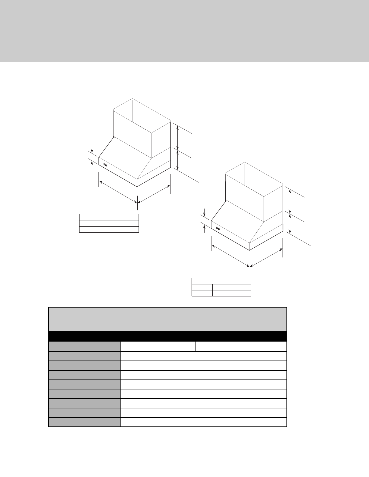
(VWH 10”H./12”H. Wall Hoods w/Standard Ventilator 30”, & 36”)
* Disregard when using recirculating kits.
460 CFM blower is shipped with hood.
NOTE: Optional duct cover sold separately.
VWH/CVWH 10”H./12”H. Wall Hoods
w/Standard Ventilator
Description 30” 36”
Duct cover width
29-7/8” (75.9 cm) 35-7/8” (91.1 cm)
Duct cover depth
12” (30.5 cm)
Duct cover height
12” (30.5 cm)
Number of lights
2
Number of filters
2
Heat lamps
N/A
Interior ventilator kit
460 CFM Standard
Interior duct size*
7” (17.8 cm)
Interior—Maximum amps
5.6 A
Dimensions & Specifications
12 ”
(30.5 cm)
10”
(25.4 cm)
5”
(12.7 cm)
A
A (Hood width)
30”W. 29-7/8“ (76.2 cm)
36”W. 35-7/8” (91.1 cm)
21”
(53.3 cm)
5”
(12.7 cm)
A
(53.3 cm)
A (Hood width)
30”W. 29-7/8“ (76.2 cm)
36”W. 35-7/8” (91.1 cm)
21”
12 ”
(30.5 cm)
12 ”
(30.5 cm)
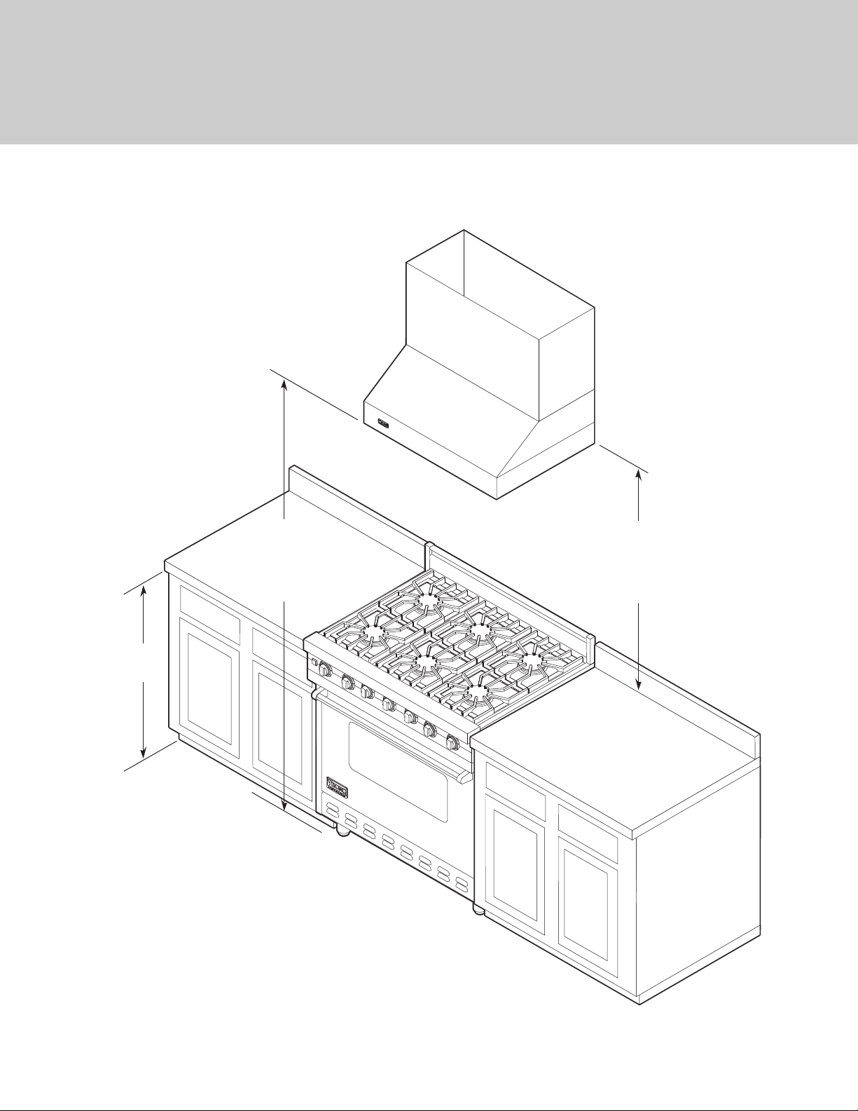
6
(VWH/CVWH 10”H./12”H. Wall Hoods w/Standard Ventilator)
Clearance Dimensions
60" min.
(152.4 cm)
to
63" max.
(160.0 cm)
36"
(91.4 cm)
* NOTE: When installing with a 24” high-shelf,
the 27” (68.6 cm) max. dimensions must be used.
24" min.
(61.0 cm)
27" max.*
to
(68.6 cm)
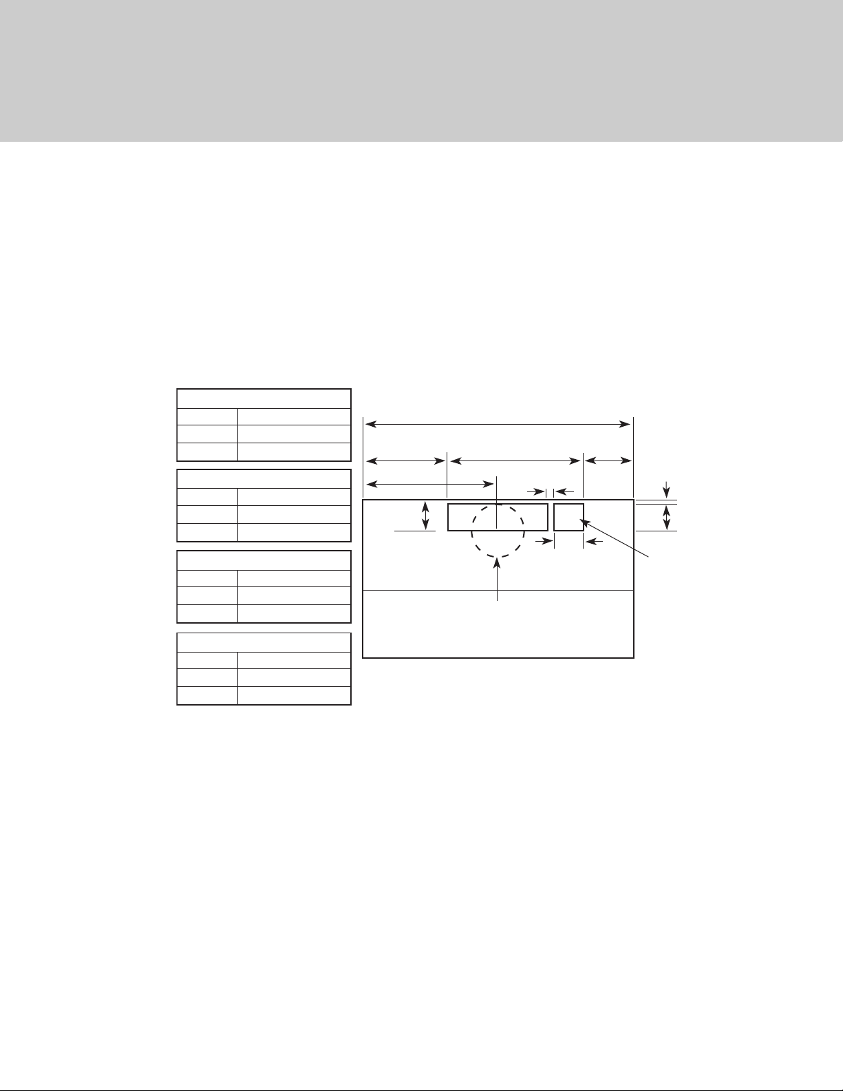
7
460 CFM Interior Ventilator Installation
Top View
(VWH/CVWH 10”H./12”H. Wall Hoods w/Standard Ventilator)
Interior Ventilator Dimensions
A
24”W. 23-7/8” (60.6 cm)
30”W. 29-7/8” (75.9 cm)
36”W. 35-7/8” (91.1 cm)
B
24”W. 5-1/4” (13.3 cm)
30”W. 8-1/4” (20.9 cm)
36”W. 11-1/4” (28.6 cm)
B
C
4”
(10.2 cm)
A
18”
(4.6 cm)
D
3-4”
(1.9 cm)
1/2”
(1.3 cm)
3-1/2”
(8.9 cm)
C
24”W. 11-15/16” (30.3 cm)
30”W. 14-15/16” (37.9 cm)
36”W. 17-15/16” (45.6 cm)
D
24”W. 5/8” (1.6 cm)
30”W. 3-5/8” (9.2 cm)
36”W. 6-5/8” (16.8 cm)
(9.8 cm)
7” (17.8 cm) dia.
duct location
3-7/8”
Electrical
hookup
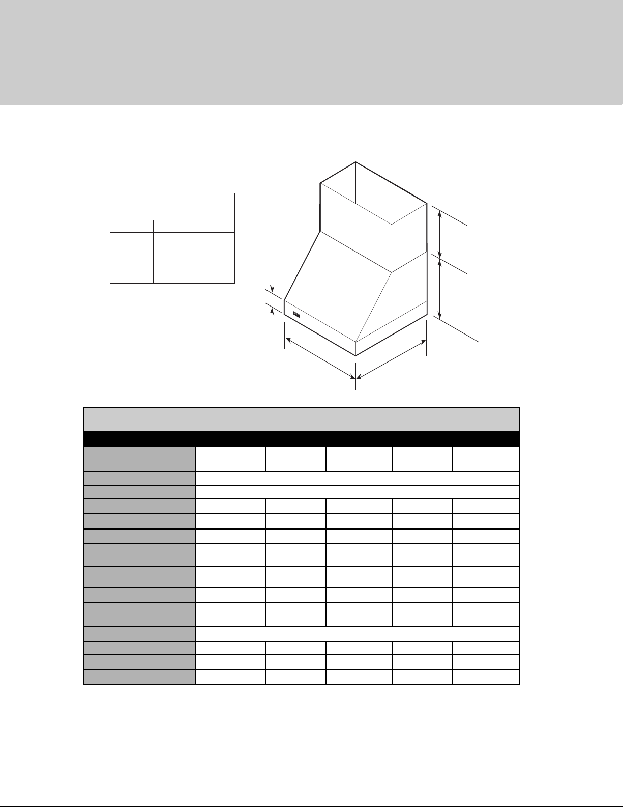
8
24"
(61.0 cm)
A
18"
(45.7 cm)
12"
(30.5 cm)
6"
(15.2 cm)
A
30" W 29-7/8" (76.2 cm)
36" W 35-7/8" (91.1 cm)
42" W 41-7/8" (106.4 cm)
48" W 47-7/8" (121.6 cm)
60" W 59-7/8" (152.1 cm)
(VWH/CVWH 18”H. 24” Deep Wall Hoods 30”, 36”, 42”, 48”, & 60”)
* A 1,200 CFM interior- or exterior-power ventilator should be used when installed over range/rangetop with gas char-grill. Max
duct run is 50 ft.
** It is recommended that the 1,500 CFM ventilator be used with longer duct runs. Max duct run is 75 ft.
NOTE: Maximum amp rating for hoods includes recommended ventilator kit rating; All products must be hard wired with 2-wire with
ground. An interior- or exterior-power ventilator kit must be purchased for installation with all 18”H. hoods.
NOTE: Optional duct cover sold separately.
VWH/CVWH 18”H. Wall Hoods
Description 30” 36” 42” 48” 60”
Duct cover width
29-7/8”
(75.9 cm)
35-7/8”
(91.1 cm)
41-7/8”
(106.4 cm)
47-7/8”
(121.6 cm)
59-7/8” (152.1
cm)
Duct cover depth
12” (30.5 cm)
Duct cover height
12” (30.5 cm)
Number of lights
2 2 2 3 4
Number of filters
2 2 2 3 4
Heat lamps
1 1 1 2 3
Interior ventilator kits
VINV300/
600/1200
VINV300/
600/1200
VINV600/
1200
VINV1200* VINV1200*
Exterior ventilator kits
DEV900/
1200*
DEV900/
1200*
DEV900/
1200*
DEV1200*/
1500**
DEV1200*/
1500**
In-line ventilator kits
DIL1200 DIL1200 DIL1200 DIL1200 DIL1200
Interior duct size
7”/10”
(17.8/25.4 cm)
7”/10”
(17.8/25.4 cm)
7”/10”
(17.8/25.4 cm)
10”
(25.4 cm)
10”
(25.4 cm)
Exterior duct size
10” (24.5 cm)
Interior—Maximum amps
4.2/5.2/8.2 4.2/5.2/8.2 5.2/8.2 10.8 10.8
Exterior—Maximum amps
8.0/5.3 8.0/5.3 8.0/5.3 7.8/8.5 7.8/8.5
In-Line—Maximum amps
5.3/7.2 5.3/7.2 5.3/7.2 9.6 10.0
Dimensions & Specifications
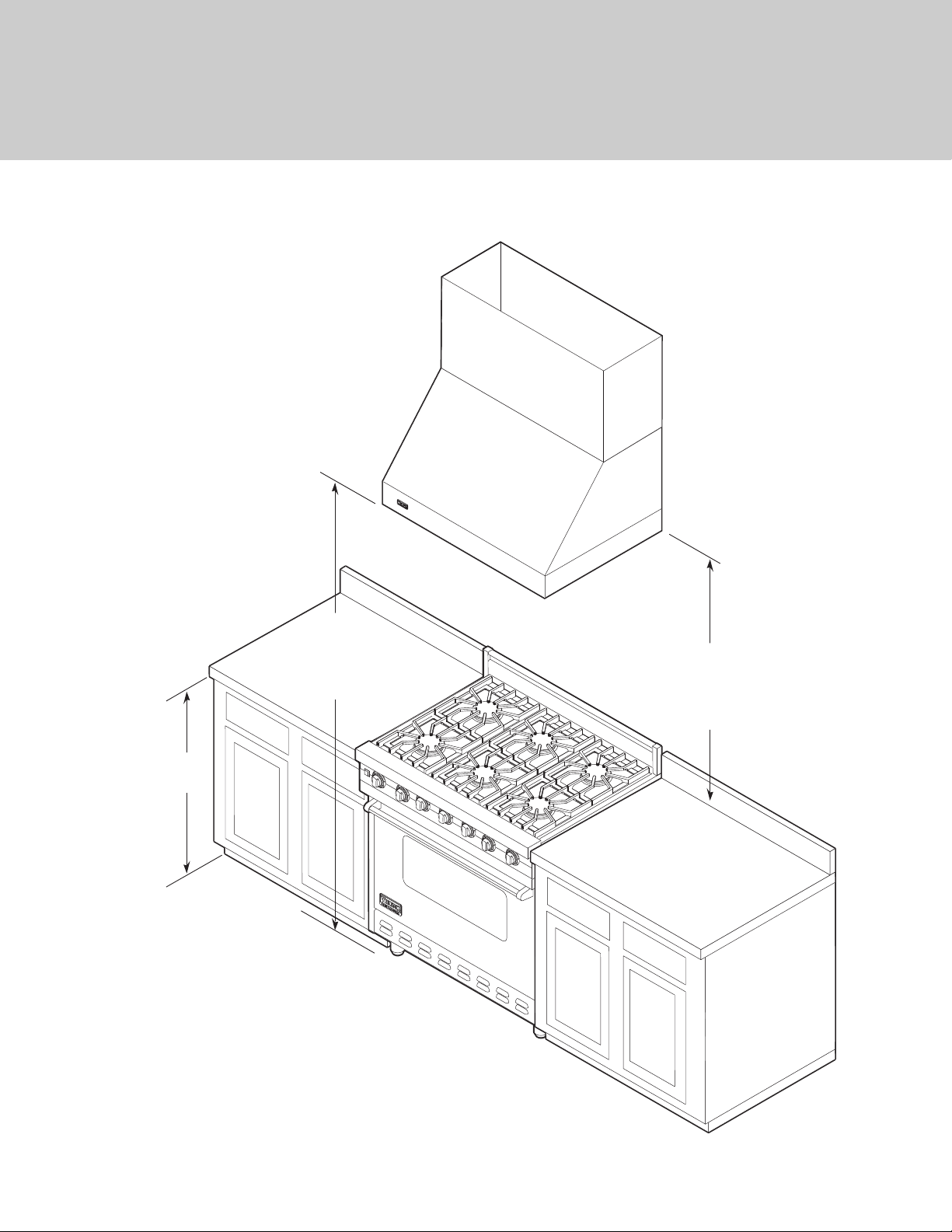
9
(VWH/CVWH 18”H. Wall Hoods)
Clearance Dimensions
36”
(91.4 cm)
66” min.
(167.6 cm)
to
72” max.
(182.9 cm)
30” min.
(76.2 cm)
to
36” max.
(91.4 cm)
10
300 or 600 CFM Interior Ventilator Installation for all Wall Hoods
1200 CFM Interior Ventilator Installation for all Wall Hoods
Top View
Top View
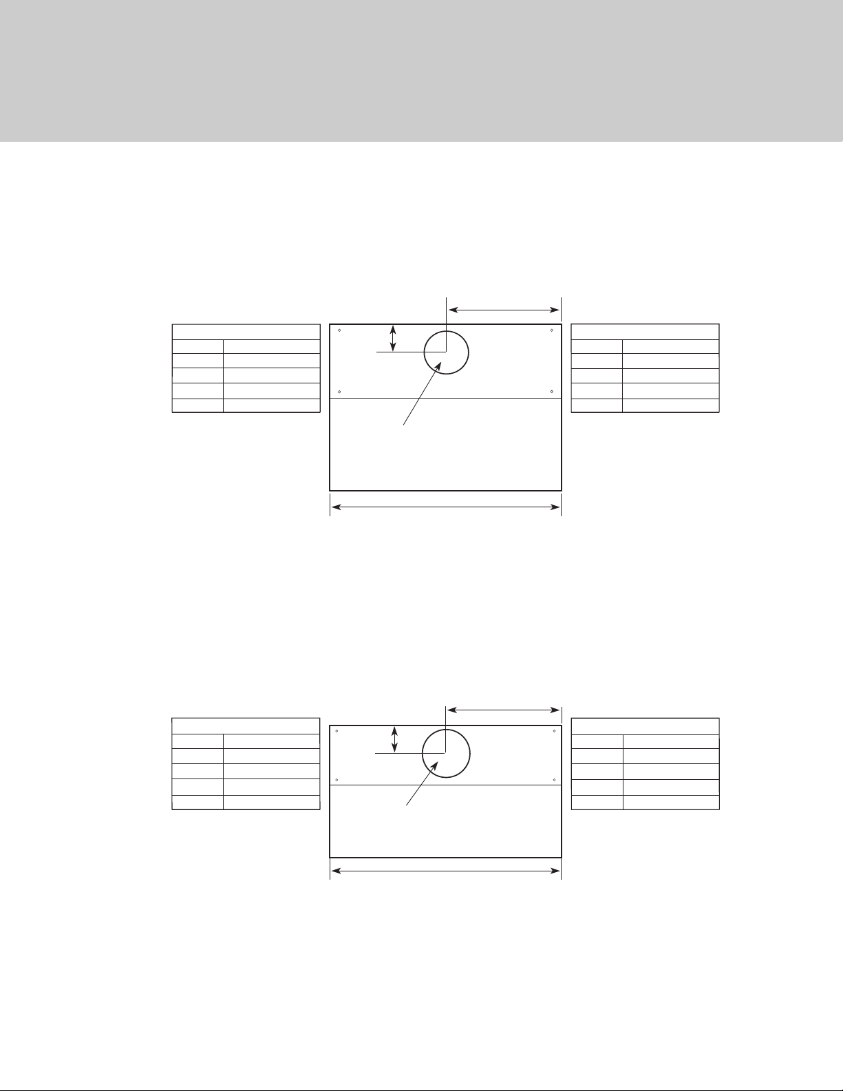
(VWH/CVWH 18”H. Wall Hoods)
Interior Ventilator Dimensions
A
A
30" W 14-15/16" (37.9 cm)
36" W 17-15/16" (45.6 cm)
42" W 20-15/16" (53.2 cm)
48" W 23-15/16" (60.8 cm)
60" W 29-15/16" (76.0 cm)
4-5/8"
(11.7 cm)
7" (17.8 cm)
dia. duct location
30" W 29-7/8" (75.9 cm)
36" W 35-7/8" (91.1 cm)
42" W 41-7/8" (106.4 cm)
48" W 47-7/8" (121.6 cm)
60" W 59-7/8" (152.1 cm)
B
B
A
A
30" W 14-15/16" (37.9 cm)
36" W 17-15/16" (45.6 cm)
42" W 20-15/16" (53.2 cm)
48" W 23-15/16" (60.8 cm)
60" W 29-15/16" (76.0 cm)
5-1/2"
(14.0 cm)
10" (25.4 cm)
dia. duct location
30" W 29-7/8" (75.9 cm)
36" W 35-7/8" (91.1 cm)
42" W 41-7/8" (106.4 cm)
48" W 47-7/8" (121.6 cm)
60" W 59-7/8" (152.1 cm)
B
B
11
900 or 1200 CFM Exterior or In-Line Ventilator Installation for all Wall
Hoods
1200 or 1500 CFM Exterior or In-Line Ventilator Installation for all Wall
Hoods
Top View
Top View
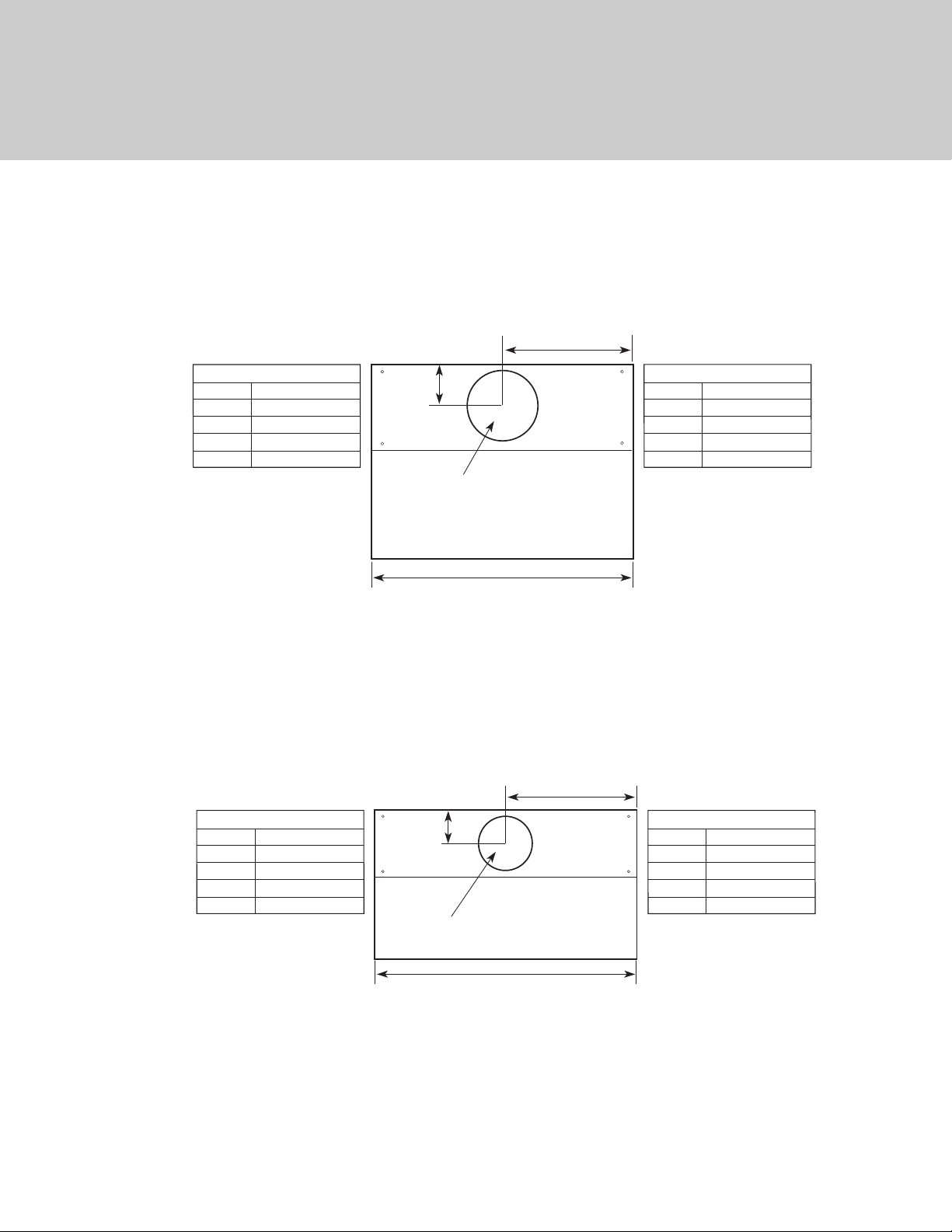
(VWH/CVWH 18”H. Wall Hoods)
Exterior Ventilator Dimensions
A
A
30" W 14-15/16" (37.9 cm)
36" W 17-15/16" (45.6 cm)
42" W 20-15/16" (53.2 cm)
48" W 23-15/16" (60.8 cm)
60" W 29-15/16" (76.0 cm)
5-15/16"
(15.1 cm)
10" (25.4 cm)
dia. duct location
30" W 29-7/8" (75.9 cm)
36" W 35-7/8" (91.1 cm)
42" W 41-7/8" (106.4 cm)
48" W 47-7/8" (121.6 cm)
60" W 59-7/8" (152.1 cm)
B
B
A
A
30" W 14-15/16" (37.9 cm)
36" W 17-15/16" (45.6 cm)
42" W 20-15/16" (53.2 cm)
48" W 23-15/16" (60.8 cm)
60" W 29-15/16" (76.0 cm)
5-15/16"
(15.1 cm)
10" (25.4 cm)
dia. duct location
30" W 29-7/8" (75.9 cm)
36" W 35-7/8" (91.1 cm)
42" W 41-7/8" (106.4 cm)
48" W 47-7/8" (121.6 cm)
60" W 59-7/8" (152.1 cm)
B
B
12
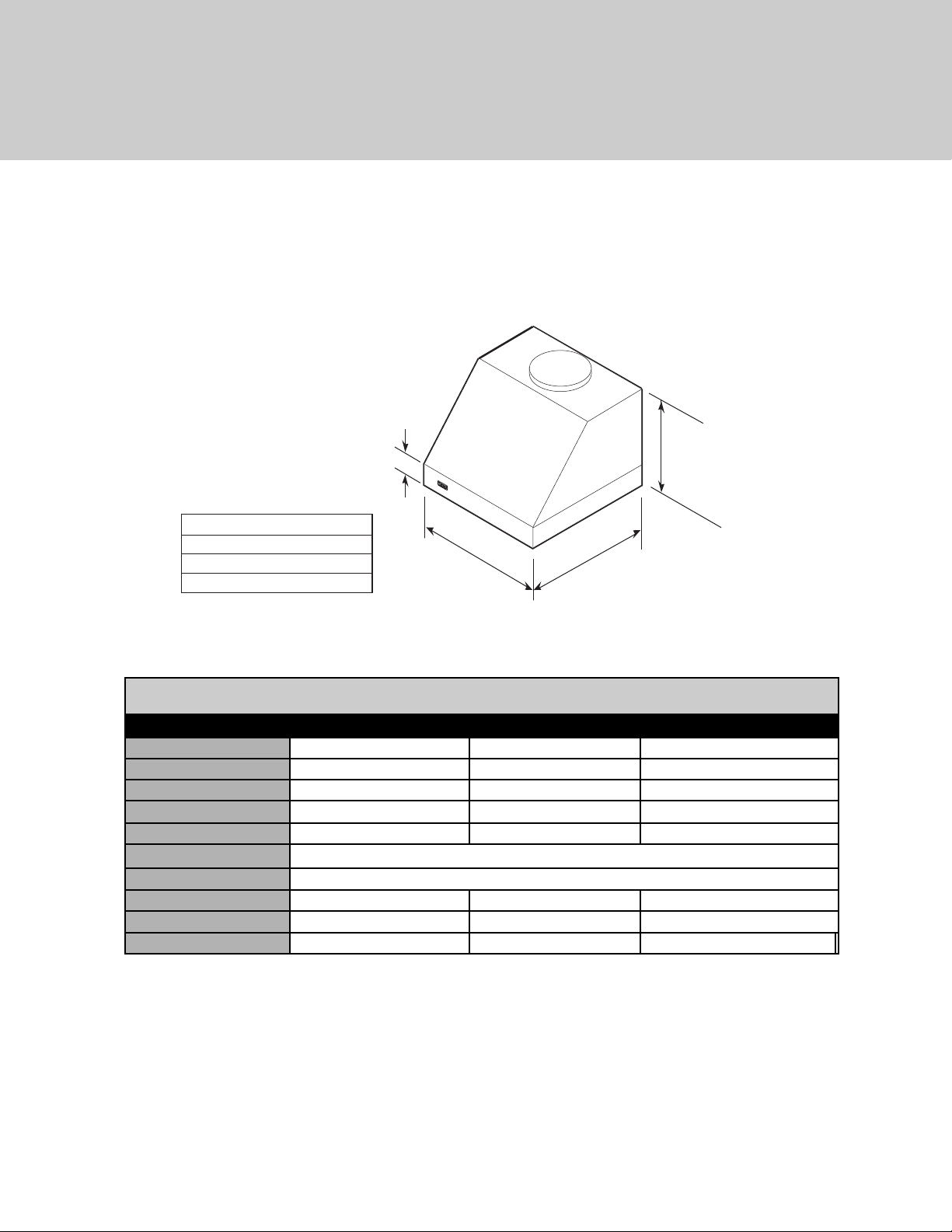
(VWHO/CVWHO 18”H. Outdoor Wall Hoods 36”, 48”, & 60”)
* A 1,200 CFM interior- or exterior-power ventilator should be used with all outdoor models and when i ndoor models are installed
over range/rangetop with gas char-grill. Max duct run is 50 ft.
** It is recommended that the 1,500 CFM ventilator be used with longer duct runs. Max duct run is 75 ft.
NOTE: Maximum amp rating for hoods includes recommended ventilator kit rating; All products must be hard wired with 2-wire with
ground. An interior- or exterior-power ventilator kit must be purchased for installation with all 18”H. hoods.
VWHO/CVWHO 18”H. Outdoor Wall Hoods
Description 36” 48” 60”
Number of lights
2 3 4
Number of filters
2 3 4
Interior ventilator kits
VINV1200* VINV1200* VINV1200*
Exterior ventilator kits
DEV1200*/1500** DEV1200*/1500** DEV1200*/1500**
In-line ventilator kits
DIL1200 DIL1200 DIL1200
Interior duct size
10” (25.4 cm)
Exterior duct size
10” (25.4 cm)
Interior—Maximum amps
9.0 11.4 11.8
Exterior—Maximum amps
6.1/6.8 8.4/9.1 8.8/9.5
In-Line—Maximum amps
7.9 10.2 10.6
Dimensions & Specifications
6"
(15.2 cm)
(45.7 cm)
A
36" W 35-7/8" (91.1 cm)
48" W 47-7/8" (121.6 cm)
60" W 59-7/8" (152.1 cm)
A
27"
(68.6 cm)
18"
 Loading...