


Installation Guide
Microwave Built-In Trim Kit
Table of Contents
Warnings & Important Information ———————————————————————— 2
Specifications ————————————————————————————————— 3
General Information ——————————————————————————————— 4
Parts Included in the Kit ————————————————————————— 4
Cabinet or Wall Cutout —————————————————————————— 4
Electrical Outlet Location ————————————————————————— 4
Installation ——————————————————————————————————— 5
Mounting Template ——————————————————————————— 5
Bottom Duct Assembly —————————————————————————— 6
Mounting Bracket Assembly ——————————————————————— 6
Cabinet Installation ——————————————————————————— 7
Frame Assembly ————————————————————————————— 7
Side Decoration Assembly (For Surface Mount Only) ————————————— 8
Over Oven Installation —————————————————————————— 8
Performance Checklist ————————————————————————————— 8
IMPORTANT–
• Before beginning, please read these
instructions completely and carefully.
• Be sure to DISCONNECT THE PLUG of the
microwave oven from the electrical outlet
before installing the built-in trim kit. Remove
the turntable from the oven cavity.
• Because the kit includes metal parts, caution
should be used in handling and installation
to avoid the possibility of injury.
• Do not remove permanently affixed labels,
warnings, or plates from the product. This
may void the warranty.
• Please observe all local and national codes
and ordinances.
• The installer should leave these instructions
with the consumer who should retain for local
inspector’s use and for future reference.
Please Read and Follow!
WARNING
This built-in trim kit is designed for use ON LY
with microwave ovens specifying built-in trim
kit RDMTK302 on the rating label on the left
side wall of the oven cavity.
E
2
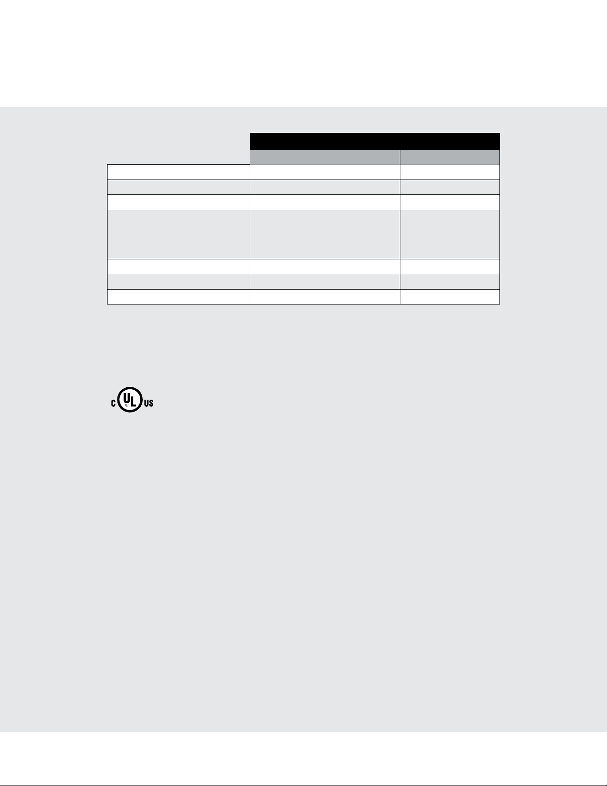
Specifications
Microwave Oven Built-In Trim Kit
RVM320 / CRVM320 RVMTK330
Overall Width 24" (60.9 cm) 29-1/2" (74.9 cm)
Overall Height from Bottom 13-3/8" (33.9 cm) 17-1/4" (43.7 cm)
Overall Depth from Rear 19-1/8" (48.7 cm) NA
Oven Interior Width
Height
Depth
Overall
Electrical Requirements 120VAC/60 Hz NA
Max. Amp Usage 1.5 KW 13 amps NA
Approx. Shipping Wt. 46 lbs. (20.9 kg) 15 lbs. (6.9 kg)
In compliance with standards set by:
FCC – Federal Communications Commission Authorized.
DHHS – Complies with Department of Health and Human Services (DHHS) rule, CFR, Title 21,
Chapter I, Subchapter J.
17-3/8"
10-1/2"
18-5/8"
2.0 cu. ft.
(4 4.1 c m)
(26.6 cm)
(47. 3 c m)
NA
– This symbol on the Rating label means the product is listed by Underwriters
Laboratories, Inc. for use in USA or Canada.
3
E
General Information
(SURFACE MOUNTING ONLY)
1) Frame Assembly: QTY 1 2) Bottom Duct Assembly: QTY 1
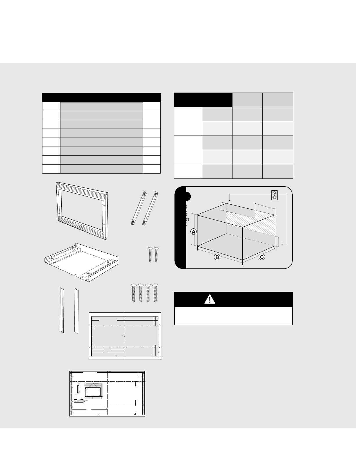
Parts Included in the Kit
Item Part Name QTY
Frame Assembly 1
1
Bottom Duct 1
2
Mounting Bracket 2
3
Screw A :1-3/16" length 2
4
Screw B: 1-3/4" length 4
5
Side Decoration
6
Surface Mounting Template 1
7
Flush Mounting Template 1
8
1
2
(Surface Mount Only)
3
4
Cabinet or Wall Cutout
Cutout Dimensions
Height A
Minimum
Flush
Mount
17-5/16"
(439.8mm)
Width B
Maximum
Minimum
N/A 16-13/16"
29-5/8"
(752.5mm)
2
Depth C
Maximum
Minimum
N/A 28"
20"
(503mm)
1
4"(10.2 cm)
figure
Surface
Mount
16-9/16"
(420.7mm)
(427mm)
27-3/4"
(704.9mm)
(711. 2 mm)
20"
(503mm)
6"(15.2 cm)
4"(10.2 cm)
5
6
7
Maximum Cutout Opening Width 28" (711.2 mm)
Minimum Cutout Opening Width 27-3/4" (704.9 mm)
1. Align the Surface Mounting Template center line with the
center of the cabinet. Align the Floor Line with the bottom
of the cabinet at the desired height. Tape it into place.
2. Predrill 4 holes marked A with a ¹₁₆" drill bit.
Center Line
BUILT-IN TRIM KIT
3. Cut the cabinet opening between the minimum and
maximum cutout opening lines. Be careful to cut precisely
along the Floor Line of the cutout.
4. Remove template from the cabinet.
CABINET CUTOUT LINE
Distance between holes A9.1" (231.2 mm)
Cutout Opening Height 17-5/16" (439.8 mm)
1/4" (6.35 mm)1/4" (6.35 mm)
4-3/16" (106.4 mm)
TINSKB181MRR0
Align Side Spacer-R to this line
SIDE SPACER TEMPLATE - R
BUILT-IN TRIM KIT
SURFACE MOUNTING TEMPLATE
FOR DESIGNER SERIES MICROWAVE OVEN
Distance between holes A9.1" (231.2 mm)
14-1/4" (361.95 mm)
14" (355.6 mm)
1/4"
(6.2 mm)
Floor Line of Cutout Opening
8
E
E
SIDE SPACER TEMPLATE - L
Cutout Opening Width 29-5/8" (752.5 mm)
CABINET CUTOUT LINE
Edges to align Side Spacer Templates (R and L)
13-1/2" min. height
Side Spacer - L Side Spacer - R
13/16" Min.
FIGURE 1
15/16 Max.
Align Side Spacer-L to this line
Side Spacer (2 required)
Must protrude from edge of cabinet
cutout towards center as shown.
24" min. width
Bottom Spacer centered with cabinet cutout
27-7/8" max. width
FIGURE 3
FIGURE 2
Bottom Spacer (1 required) ¹₄" plywood
14" (355.9 mm)
14-13/16" (376.2 mm)
FLOOR LINE OF CUTOUT OPENING
CENTER LINE
1-9/16" (39.7 mm)
Bottom and Side
Spacer (R and L) Offset
CABINET CUTOUT LINE
FLUSH MOUNTING TEMPLATE
FOR DESIGNER SERIES MICROWAVE OVEN
1. Align the Flush Mounting Template center line with the center of the
cabinet. Align the Floor Line with the bottom of the cabinet at the
desired height. Tape it in place.
2. Cut the cabinet opening along the three Cabinet Cutout Lines and
the Floor Line.
3. Install two Side Spacers (see FIGURE 1) and one Bottom Spacer (see
FIGURE 2) as specified in FIGURE 3. Be sure to offset all three spacers
by 1⁹₁₆" from the front surface of the cabinet.
4. Cut out the Side Spacer Templates (R and L) and align the indicated
edge to the corresponding Side Spacer (see FIGURE 3). Be careful to
align the Floor Line to the bottom edges of the Side Spacers.
5. Predrill two holes indicated “A“ in Side Spacer - R with a ¹₁₆" drill bit.
6. Predrill two holes indicated ”B“ in Side Spacer - L with a ¹₁₆" drill bit.
7. Remove template from the cabinet.
Electrical Outlet Location
CAUTION
Outlet should NOT be in the shaded area as
indicated on figure 1.
NOTES:
Maximum Cutout Opening Height 16-13/16" (427 mm)
Minimum Cutout Opening Height 16-9/16" (420.7 mm)
3-15/16" (100 mm)
TINSKB180MRR0
• IftheDepth(C)dimensionisgreaterthan21"
1/4"
(6.2 mm)
(53.3cm), the outlet location may be in any
areaontherearwall.
• Theooroftheopeningshouldbeconstructed
ofplywoodstrongenoughtosupporttheweight
oftheovenandoorload(approximately100
pounds).Theoorshouldbelevelforproper
operation of theoven. Be sureto check the
localbuildingcodeasitmayrequirethatthe
openingbee n cl o sedwithside,ceilingandrear
partition.Theproperfunctioningoftheoven
doesnotrequiretheenclosure.
4
4
Installation
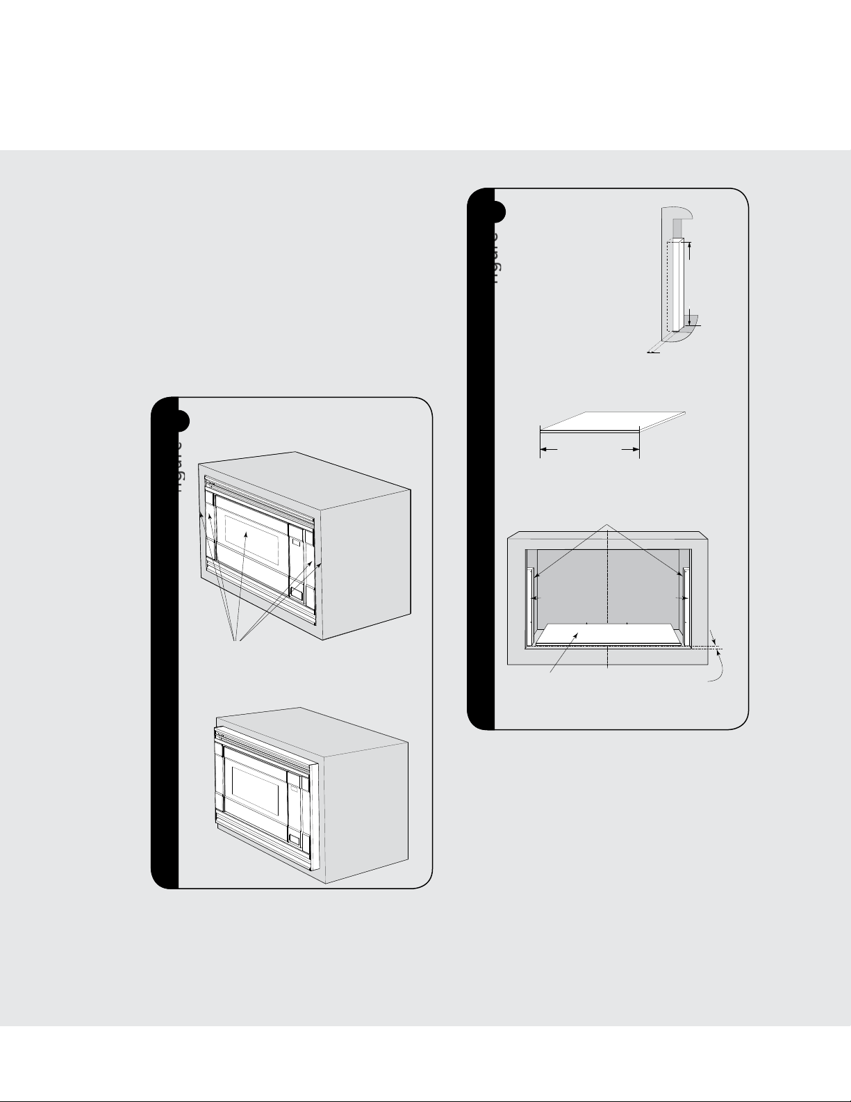
b. Surface Mount Configuration -
Microwave Oven and Frame Assembly
protrude from the surface of the cabinet.
Illustration 2
a. Flush Mount Configuration -
Microwave Oven and Frame Assembly
glass are flush with the cabinet
Mounting Template
Determine which mounting method to use
based on the required configuration. See figure
2A for FLUSH MOUNT and 2B for SURFACE
MOUNT.
Align the template corresponding to the required
mounting method to the center of the cabinet.
Make sure that the template is level with the
floor. Tape it into place. Cut the cabinet opening
along the lines specified on the template. Leave
template taped in place.
FLUSH MOUNT CONFIGURATION—
A
2
figure
Microwave Oven and Frame Assembly glass
are flush with the cabinet.
3
SIDE SPACER—2
A
REQUIRED. Must
protrude from edge of
cabinet cutout towards
center as shown.
figure
13-1/2" m in.
13/16" min.
15/16" max.
BOTTOM SPACER—1
B
REQUIRED. 1/4" plywood.
24" min. width
27-7/8" max. width
C
EDGES TO ALIGN SIDE SPACER
TEMPLATES (R and L)
Side Spacer (L) Side Spacer (R)
Indicated surfaces are flush.
SURFACE MOUNT CONFIGURATION
B
—Microwave Oven and Frame Assembly
protrude from the surface of the cabinet.
For SURFACE MOUNT, predrill 4 holes marked “A” with a
1/16" drill bit. Remove template from the cabinet. Go to
Bottom Duct Assembly.
BOTTOM SPACER
CENTERED with
CABINET CUTOUT
For FLUSH MOUNT, two (2) side spacers and one (1) bottom
spacer are required. Spacers are not included in the kit and
must be fabricated by installer. See figures 3A and B for
spacer requirements. Make sure that all three spacers are
offset from the front of the cabinet by 1-9/16".
1-9/16" (39.7 mm)
BOTTOM and SIDE
SPACER (R and L) offset
Cut out the Side Spacer Templates (R and L)
from the Flush Mounting Template. Align the
indicated edges to the corresponding right and
left side spacers as shown in figure 3. Make sure
to align the bottom edges of the side spacer
templates to the floor of the cabinet opening.
Predrill two (2) holes marked “A” on Side Spacer
Template – R and two (2) holes marked “B” on
Side Spacer Template – L with 1/16" drill bit.
Remove templates from the cabinet.
5
E

Installation
Illustration 6 - for Flush Mount
Illustration 7 - for Surface Mount
Bottom Duct Assembly
4
CENTER THE
BOTTOM DUCT
figure
MAKE BOTTOM FLANGE
FLUSH WITH BOTTOM
SPACER
Place the Bottom Duct in the cabinet opening. For FLUSH
MOUNT, it will rest on the bottom spacer centered with
the cabinet. See figure 4.
5
figure
SCREW A
BOTTOM DUCT
CENTER THE
BOTTOM DUCT
Mounting Bracket Assembly
Position the mounting brackets to align with the
predrilled holes that were drilled with the mounting
template.
6
A
figure
figure
B
FLUSH MOUNT BRACKET
SCREW B
SURFACE MOUNT BRACKET
E
SCREW A
MAKE BOTTOM FLANGE
FLUSH WITH CABINET
For SURFACE MOUNT, the Bottom Duct will rest on the
floor of the opening. See figure 5.
BOTTOM DUCT
Align the Bottom Duct to the center of the
opening with the bottom flange securely flush
with the bottom spacer (for FLUSH MOUNT) or
the cabinet (for SURFACE MOUNT).
Secure the Bottom Duct Assembly with the two (2)
SCREWS A. See figures 4 and 5 respectively.
SCREW B
The enclosed ends of the mounting brackets should face
inwards. Check that they are vertical and then secure loosely
with four (4) Screws B. See figure 6.
7
27-1/2"
(698.5mm)
figure
figure
EQ. EQ.
6
Installation
CABINET INSTALL FRAME INSTALL CABINET INSTALL
Align the mounting brackets horizontally by sliding
them back and forth along the screw slots until
the brackets are exactly 27-1/2" apart and equal
distance from the cabinet sides. See figure 7.
Once the brackets are correctly positioned,
securely tighten the four (4) screws B.
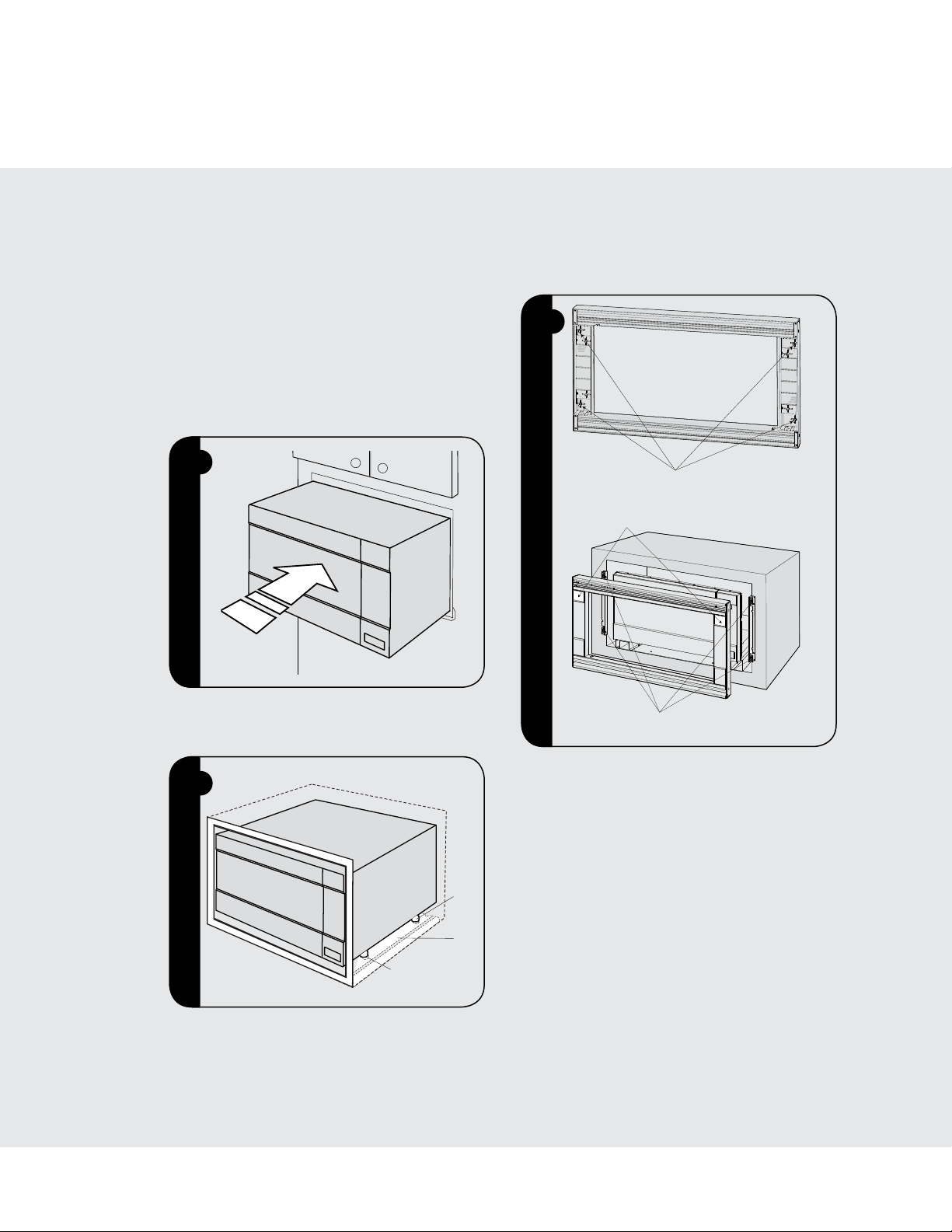
Cabinet Installation
Place the oven adjacent to the wall or cabinet
opening. Plug the power cord into the electrical
outlet.
8
figure
figure
Frame Assembly
Turn over FRAME ASSEMBLY to locate the 4 ball
studs.
!
figure
figure
4 BALL STUDS ON BACK OF FRAME ASSEMBLY
SMALL STAINLESS DECORATIONS ON TOP
Carefully guide the assembled oven into the prepared
opening. Slide the oven onto the Bottom Duct Assembly.
9
figure
figure
Avoid pinching the cord between the oven and the wall.
Adjust the position of the oven so that the feet of the oven
are fitted into the recesses of the Bottom Duct Assembly.
See figure 8.
S
ee figure 9.
BOTTOM
ASSEMBLY
DUCT RECESS
FOOT
DUCT
Position the FRAME ASSEMBLY with the small
stainless decorations on top. Align the 4 ball studs
with the 4 snap attachments at both ends of the
MOUNTING BRACKETS.
Secure the FRAME ASSEMBLY by firmly pushing
it onto the Mounting Brackets engaging the four
(4) snap attachments. See figure !.
SNAP ATTACHMENT LOCATIONS ON
MOUNTING BRACKETS
7
E

Installation
Side Decoration Assembly
(For Surface Mount Only)
"
figure
ALIGN TOP
SURFACE OF SIDE
DECORATION TO
TOP SURFACE OF
FRAME ASSEMBLY
FRONT INNER EDGE
OF SIDE DECORATION
FRONT SIDE EDGE OF FRAME ASSEMBLY
Peel the backing off the tape on the backside of
the SIDE DECORATIONS. Align the front inner
edge of the side decorations to the front side
edge of the FRAME ASSEMBLY.
Align the top surface of the side decorations to the
top surface of the FRAME ASSEMBLY. Secure the
side decorations by pressing them firmly against
the side of the FRAME ASSEMBLY. See figure ".
Over Oven Installation
#
figure
figure
2" (5.1 CM) FOR 30" W LOWER OVEN
Performance Checklist
1. Make sure the unit has been installed according
to all of the Installation Instructions and the
required Mounting Template.
2. Plug in the power cord.
3. Keep the Use & Care Manual and Installation
Manual.
Viking Range, LLC
111 Front Street
Greenwood, Mississippi 38930 USA
(662) 455-1200
For product information
call 1-888-845-4641
E
8

Guide d’installation
Kit de garniture à encastrer pour
four à micro-ondes

Table des matières
Avertissements et Information importante ————————————————————— 10
Spécifications ————————————————————————————————— 11
Information générale
Pièces comprises dans le kit ——————————————————————— 12
Découpe de l’armoire ou du mur ————————————————————— 12
Emplacement de la prise électrique ———————————————————— 12
Installation —————————————————————————————————— 13
Gabarit de fixation ———————————————————————————— 13
Pose du conduit inférieur ————————————————————————— 14
Brides de fixation ———————————————————————————— 14
Installation dans l’armoire ————————————————————————— 15
Cadre de porte ————————————————————————————— 15
Décorations latérales (pour fixation en surface uniquement) —————————— 16
Installation au dessus d’un four —————————————————————— 16
Liste de contrôle du rendement ————————————————————————— 16
IMPORTANT–
• Prière de lire attentivement toutes ces
directives avant de commencer.
• Veiller à DÉBRANCHER LA FICHE du four
à micro-ondes de la prise électrique avant
d’installer la garniture à encastrer. Retirer la
table tournante de la cavité du four.
• Le kit comprend des parties métalliques, il
faut faire attention lors de la manipulation
et de l’installation pour éviter éventuelles
blessures.
• Ne pas retirer de façon permanente les
étiquettes, les mises en garde ou les plaques
fixées au produit. Cela pourrait annuler la
garantie.
• Veuillez observer tous les codes et règlements
locaux et nationaux.
• L’installateur devra laisser ces directives au
client qui devra les conserver pour l’usage
d’un inspecteur local et pour référence
ultérieure.
Prière de lire et d’observer!
AVERTISSEMENT
Ce kit à encastrer est conçu pour être utilisé
uniquement avec les fours à micro-ondes
spécifiant kit à encastrer RDMTK302 sur
l’étiquette des spécifications nominales sur la
paroi gauche de la cavité du four.
F
10

Specifications
Four à micro-ondes
RVM320 / CRVM320 RVMTK330
Largeur hors tout 24 po (609 mm) 29-1/2 po (749 mm)
Hauteur hors tout depuis le bas 13-3/8 po (339 mm) 17-1/4 po (437 mm)
Profondeur hors tout depuis l’arrière 19-1/8 po (487 mm) S/O
Intérieur du four Largeur
Hauteur
Profondeur
Hors tout
Alimentation électrique 120VAC/60 Hz S/O
Max. Ampèrage max. 1,5 KW 13 amps S/O
Poids approx. à l’expédition. 46 lb. (20,9 kg) 15 lb. (6,9 kg)
En conformité avec les normes établies par :
FCC – Autorisé par la Federal Communications Commission.
DHHS – Conforme au règlement du Department of Health and Human Services (DHHS), CFR, Titre
21, Chapitre I, Souschapitre J.
– Ce symbole sur l’étiquette des spécifications nominales signifie que le produit est sur la liste
des Underwriters Laboratories, Inc. pour une utilisation aux É.-U. ou au Canada.
17-3/8 po
10-1/2 p o
18-5/8 po
2 pi3
(441 mm)
(266 mm)
(473 mm)
(0,04 m3)
Kit de garniture à
encastrer
S/O
11
F

Information générale
(SURFACE MOUNTING ONLY)
1) Frame Assembly: QTY 1 2) Bottom Duct Assembly: QTY 1
Pièces comprises dans le kit
Numéro Nom de pièce Qté
Cadre de porte 1
1
Conduit inférieur 1
2
Bride de fixation 2
3
Vis A : longueur 1-3/16 po (30,2 mm) 2
4
Vis B : longueur 1 3/4 po (44,5 mm) 4
5
1
2
Décorations latérales (pour fixation
6
en surface uniquement)
Gabarit de fixation en surface 1
7
Gabarit de fixation encastrée 1
8
3
4
2
Découpe de l’armoire ou
du mur
Dimensions de la
découpe
Hauteur A
Largeur B
Profondeur C
1
Minimum
Maximum
Minimum
Maximum
Minimum
4 po (102 mm)
figure
Fixation
encastrée
17-5/16 po
(4 3 9, 8 mm)
Fixation en
surface
16-9/16 po
(420,7 mm)
N/A 16 -13 /16p o
(427 mm)
29-5/8 po
(752,5 mm)
27-3/4 po
(704,9 mm)
N/A 28 po
(711, 2 mm)
20po
(503mm)
20po
(503mm)
6 po (15,2 mm)
4 po (102 mm)
5
6
7
Maximum Cutout Opening Width 28" (711.2 mm)
Minimum Cutout Opening Width 27-3/4" (704.9 mm)
1. Align the Surface Mounting Template center line with the
center of the cabinet. Align the Floor Line with the bottom
of the cabinet at the desired height. Tape it into place.
2. Predrill 4 holes marked A with a ¹₁₆" drill bit.
Center Line
BUILT-IN TRIM KIT
FLUSH MOUNTING TEMPLATE
FOR DESIGNER SERIES MICROWAVE OVEN
3. Cut the cabinet opening between the minimum and
maximum cutout opening lines. Be careful to cut precisely
along the Floor Line of the cutout.
4. Remove template from the cabinet.
CABINET CUTOUT LINE
Distance between holes A9.1" (231.2 mm)
Cutout Opening Height 17-5/16" (439.8 mm)
1/4" (6.35 mm)1/4" (6.35 mm)
4-3/16" (106.4 mm)
TINSKB181MRR0
Align Side Spacer-R to this line
SIDE SPACER TEMPLATE - R
BUILT-IN TRIM KIT
SURFACE MOUNTING TEMPLATE
FOR DESIGNER SERIES MICROWAVE OVEN
Distance between holes A9.1" (231.2 mm)
14-1/4" (361.95 mm)
14" (355.6 mm)
1/4"
(6.2 mm)
Floor Line of Cutout Opening
8
SIDE SPACER TEMPLATE - L
Cutout Opening Width 29-5/8" (752.5 mm)
CABINET CUTOUT LINE
Edges to align Side Spacer Templates (R and L)
13-1/2" min. height
Side Spacer - L Side Spacer - R
13/16" Min.
FIGURE 1
15/16 Max.
Align Side Spacer-L to this line
Side Spacer (2 required)
Must protrude from edge of cabinet
cutout towards center as shown.
24" min. width
Bottom Spacer centered with cabinet cutout
27-7/8" max. width
FIGURE 3
FIGURE 2
Bottom Spacer (1 required) ¹₄" plywood
14" (355.9 mm)
14-13/16" (376.2 mm)
FLOOR LINE OF CUTOUT OPENING
CENTER LINE
1-9/16" (39.7 mm)
Bottom and Side
Spacer (R and L) Offset
CABINET CUTOUT LINE
1. Align the Flush Mounting Template center line with the center of the
cabinet. Align the Floor Line with the bottom of the cabinet at the
desired height. Tape it in place.
2. Cut the cabinet opening along the three Cabinet Cutout Lines and
the Floor Line.
3. Install two Side Spacers (see FIGURE 1) and one Bottom Spacer (see
FIGURE 2) as specified in FIGURE 3. Be sure to offset all three spacers
by 1⁹₁₆" from the front surface of the cabinet.
4. Cut out the Side Spacer Templates (R and L) and align the indicated
edge to the corresponding Side Spacer (see FIGURE 3). Be careful to
align the Floor Line to the bottom edges of the Side Spacers.
5. Predrill two holes indicated “A“ in Side Spacer - R with a ¹₁₆" drill bit.
6. Predrill two holes indicated ”B“ in Side Spacer - L with a ¹₁₆" drill bit.
7. Remove template from the cabinet.
F
Emplacement de la prise
électrique
MISE EN GARDE
La prise NE doit PAS se trouver dans l’aire
ombrée comme indiqué à l’Illustration 1.
Maximum Cutout Opening Height 16-13/16" (427 mm)
Minimum Cutout Opening Height 16-9/16" (420.7 mm)
3-15/16" (100 mm)
TINSKB180MRR0
NOTES :
1/4"
(6.2 mm)
• Silaprofondeur(C)dépasse53,3cm(21po),
l’emplacement de la prise peut être situé
n’importeoùsurlemurarrière.
• Leplancher de l’ouverture doit être en
contreplaquéassezfortpoursupporterlepoids
dufouretsa proprecharge(environ45,5kg
[100 lb]).Ildoit êtreà unniveau convenable
pourl’utilisationdu four. Veillerà vérierle
codelocaldubâtiment,carilpourraitexiger
que l’ouverture soit fermée par une cloison
latérale,arrièreetunplafond.Lefourn’apas
besoind’êtreenclospourfonctionner.
12

Installation
b. Surface Mount Configuration -
Microwave Oven and Frame Assembly
protrude from the surface of the cabinet.
Illustration 2
a. Flush Mount Configuration -
Microwave Oven and Frame Assembly
glass are flush with the cabinet
Installation
Gabarit de fixation
Déterminer la méthode de fixation selon la
configuration requise. Voir la figure 2A pour la
fixation ENCASTRÉE et 2B pour la fixation en
SURFACE.
Aligner le gabarit correspondant à la méthode de
fixation requise avec le centre de l'armoire. Veiller
à ce que le gabarit soit horizontal. Coller en place
avec du ruban adhésif. Découper l'ouverture de
l'armoire selon les lignes indiquées sur le gabarit.
Laisser le gabarit en place.
CONFIGURATION POUR FIXATION
A
2
figure
ENCASTRÉE—Le four à microondes et le
verre du cadre de porte sont encastrés dans
l’armoire.
3
ENTRETOISE
A
LATÉRALE—2. Doit
dépasser du bord de la
découpe de l’armoire
vers le centre comme
figure
illustré.
13/16 po (20,6 mm) min
15/16 po (23,8 mm) max
ENTRETOISE INFÉRIEURE—1.
B
Contreplaqué 1/4 po (6,35 mm)
Largeur min 24 po
27-7/8" max. width
C
Entretoise
Side Spacer (L) Side Spacer (R)
Latérale (G)
13-1/2 po
13-1/2" m in.
13/16" min.
15/16" max.
24" min. width
(609 mm)
BORDS POUR ALIGNER LES GABARITS
EDGES TO ALIGN SIDE SPACER
D’ENTRETOISE LATÉRALE (D et G)
TEMPLATES (R and L)
Largeur max 27-7/8 po
(708 mm)
Entretoise
Latérale (D)
min
(342,9 mm)
Les surfaces indiquées affleurent.
SURFACE MOUNT CONFIGURATION
B
—Le four à microondes et le verre du cadre de
porte font saillie de la surface de l’armoire.
Pour la fixation en surface, percer 4 trous marqués « A »
avec un foret de 1/16 po (1,6 mm). Enlever le gabarit de
l’armoire Aller au conduit inférieur.
Entretoise inférieure
BOTTOM SPACER
Centrée avec la
CENTERED with
CABINET CUTOUT
Découpe de l’armoire
Pour la fixation encastrée, il faut deux (2) entretoises
latérales et une (1) entretoise inférieure. Les entretoises
ne sont pas fournies dans le kit et doivent être fabriquées
par l’installateur. Voir figures 3A et B pour les exigences
d'entretoise. Veiller à ce que les trois entretoises dépassent
de 1-9/16 po (39,7 mm) à l'avant de l'armoire.
1-9/16 po (39,7 mm)
1-9/16" (39.7 mm)
Déport d’entretoises
BOTTOM and SIDE
SPACER (R and L) offset
Inférieure et Latérales
(D et G)
Découper les gabarits d’entretoise latérale (D et
G) du gabarit de montage encastré. Aligner les
bords indiqués aux entretoises droite et gauche
correspondantes comme l’illustre la figure 3.
Veiller à aligner les bords inférieurs des gabarits
d'entretoise latérale avec le plancher de l'ouverture
de l'armoire. Percer deux (2) trous marqués « A »
sur un gabarit D d'entretoise latérale et deux (2)
trous marqués « B » sur un gabarit G d'entretoise
latérale avec un foret de 1/16 po (1,6 mm).
Enlever les gabarits de l'armoire.
13
F

Installation
Illustration 6 - for Flush Mount
Illustration 7 - for Surface Mount
Conduit inférieur
4
CENTRER LE
CENTER THE
CONDUIT
BOTTOM DUCT
figure
FAIRE AFFLEURER LA
BRIDE INFÉRIEURE AVEC
L'ENTRETOISE INFÉRIEURE
Placer le conduit inférieur dans l’ouverture de l’armoire.
Pour le montage encastré, il reposera sur l’entretoise
inférieure centrée dans l’armoire. Voir figure 4.
5
figure
INFÉRIEUR
VIS A
CENTER THE
CENTRER LE
BOTTOM DUCT
CONDUIT IN-
FÉRIEUR
CONDUIT
INFÉRIEUR
Brides de fixation
Placer les brides de fixation pour les aligner avec
les trous percés à l’aide du gabarit.
6
A
figure
figure
B
BRIDE FIXÉE ENCASTRÉE
VIS B
BRIDE FIXÉE EN SURFACE
VIS A
FAIRE AFFLEURER LA BRIDE
INFÉRIEURE AVEC L’ARMOIRE
Pour la fixation en surface,le conduit inférieur reposera sur
le plancher de l’ouverture. Voir figure 5.
CONDUIT
INFÉRIEUR
Aligner le conduit inférieur au centre de l’ouverture
avec la bride inférieure affleurant l’entretoise
inférieure (pour la FIXATION ENCASTRÉE) ou
l’armoire (pour la FIXATION EN SURFACE).
Fixer le conduit inférieur avec deux VIS A
(2-3/16 po [ 55,6 mm]). Voir figures 4 et 5
respectivement.
VIS B
Les extrémités encastrées des brides de fixation doivent
faire face à l’intérieur. Vérifier qu’elles sont verticales et les
fixer à demi avec quatre (4) VIS B. Voir figure 6.
7
27-1/2 po
(698,5 mm)
figure
figure
EQ. EQ.
F
14

Installation
CABINET INSTALL FRAME INSTALL CABINET INSTALL
Aligner les brides de fixation horizontalement en
les faisant glisser vers l'avant et l'arrière le long
des fentes de vis jusqu'à ce que les brides soient
exactement séparées de 27-1/2 po (698,5 mm)
et à égale distance des côtés de l'armoire. Voir
figure 7.
Une fois les brides correctement placées, bien les
fixer avec quatre (4) vis B.
Installation dans l'armoire
Placer le four près de l'ouverture du mur ou de
l'armoire. Brancher le cordon d'alimentation dans
la prise électrique.
8
figure
figure
Cadre de porte
Retourner le CADRE DE PORTE pour repérer les
quatre pivots à rotule.
!
figure
figure
QUATRE PIVOT À ROTULE À L’ARRIÈRE DU CADRE DE PORTE
PETITES DÉCORATIONS EN ACIER INOX SUR LE DESSUS
EMPLACEMENT DES FIXATIONS À PRESSION
Guider avec précaution le four assemblé dans l'ouverture
préparée. Faire glisser le four sur le conduit inférieur. Voir
figure 8.
9
figure
figure
ÉVIDEMENT DANS
Éviter de pincer le cordon entre le four et le mur. Ajuster la
position du four de façon à ce que ses pattes entrent dans
les évidements du conduit d'évacuation. Voir figure 9.
PATTE
CONDUIT
INFÉRIEUR
LE CONDUIT
Placer le cadre de porte avec les petites décorations
en acier inox sur le dessus. Aligner les quatre
pivots à rotule avec les fixations à pression aux
deux extrémités des BRIDES DE FIXATION.
Bien fixer le cadre de porte en le poussant
fermement sur les brides de fixation en engageant
les quatre (4) fixations à pression. Voir figure !.
SUR LES BRIDES DE FIXATION
15
F

Installation
Installation
Décorations latérales
(pour fixation en surface uniquement)
"
figure
ALIGNER LA SUR-
FACE SUPÉRIEURE
DE LA DÉCORA-
TION LATÉRALE
AVEC LA SURFACE
SUPÉRIEURE DU
CADRE DE PORTE
BORD INTÉRIEUR
AVANT DE LA DÉC-
ORATION LATÉRALE
BORD INTÉRIEUR AVANT DU CADRE DE PORTE
Retirer le papier dorsal du ruban au verso des
DÉCORATIONS LATÉRALES. Aligner le bord
intérieur avant des décorations latérales avec le
bord intérieur avant du CADRE DE PORTE.
Installation au dessus d'un
four
#
figure
figure
5,1 CM (2 po) POUR UN FOUR INFÉRIEUR DE
91,4 CM (30 po) DE LARGE
Liste de contrôle
Aligner la surface supérieure de la décoration
latérale avec la surface supérieure du CADRE DE
PORTE. Fixer les décorations latérales en pressant
fermement contre le côté du CADRE DE PORTE.
Voir figure ".
Viking Range, LLC
111 Front Street
Greenwood, Mississippi 38930 USA
(662) 455-1200
Pour plus d'information sur le produit,
Composer le 1-888-845-4641
1. Veiller à ce que l'appareil soit installé selon
les instructions et avec le bon gabarit de
fixation.
2. Brancher le cordon d'alimentation.
3. Conserver le mode d'emploi et d'entretien et
le manuel d'installation
F
F
TINSKB179MRR0
16
 Loading...