

Viking lm-12w Service Manual
Telecommunication Peripheral Products
Technical Practice
LM-12W
Wall Mounted
Status Display
January 19, 1998
Provide Large, Easy to Read, Line or
Message Status to Multiple Users
The LM-12W works in conjunction
with Viking's TMS-12A Call
Sequencer, MLC-24 Message
Lamp Controller or the LM-24M
Line Status Monitor to provide
large, easy to read, line status or
message display.
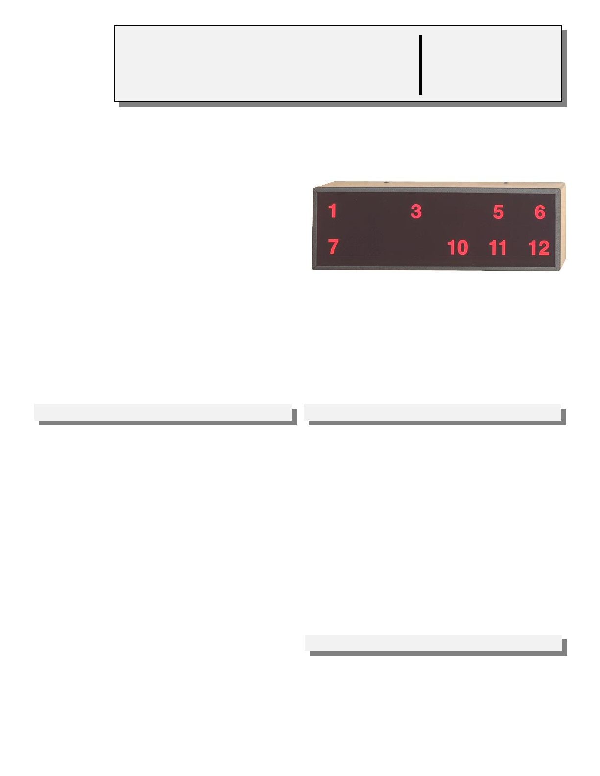
Each LM-12W is equipped to
display 12 stations and is housed
in an attractive black painted frame. The large numbers can be seen only when turned
frame.
on and are visible from over 30 feet away. Two LM-12W's can be daisy chained to
provide up to 24 stations of line or message status.
http://www.VikingElectronics.com
VIKING©
E-mail...Sales@VikingElectronics.com
Features Applications
• Large, red numbers with high intensity red back
lighting
• Metal frame with a durable textured, black
powder paint finish
• 600 ohm common audible output jack
• Relay output jack for triggering an external
alarm device in cadence with the 600 ohm
common audible output signal
• Daisy chain (2) LM-12W's to cover up to 24
stations (optional lens kit required for stations
13-24)
• Wall mountable
• Installations where multiple receptionist's are
located in one general area.
• Provides incoming call status when used with
a TMS-12A* Call Sequencer
• Provides message waiting information when
used with a MLC-24* Message Lamp Controller
• Provides line or extension status when used
with a LM-24M* Line Status Monitor
Note: Two LM-12W's are required when monitoring more
*
than 12 lines
Sales...(715) 386 - 8861
Specifications
• VR-1A jack provided for additional on-hold alert
when used in conjunction with a TMS-12A Call
Sequencer (TMS-12A requires special software)
Made in the U.S.A.
Power: 120V AC/13.8V AC 1.25A UL listed adapter provided
Dimensions: 102mm x 305mm x 53mm (4" x 12" x 2.1")
Shipping Weight: 1.1 kg (2.5 lbs)
Environmental: 0°C to 32°C (32°F to 90°F) with 5% to 95% non-
condensing humidity
Connections: (3) RJ14 jacks, (1) 3.5mm (1/8") audio jack
Display Digits: 18mm (.7") tall with high intensity red back lighting
Visibility: Approximately 9.1m (30 ft)
Mounting: Wall mountable with (2) key hole mounting slots

Installation
Power Input
Data Communications Input - Input from primary LM-
12W, TMS-12A, LM-24M, or MLC-24. Connect using a six
wire RJ25 (3 line) modular cord.
40 Pin Display Chip - Factory installed in the Z2A socket to
drive lines 1 - 12. Install in socket Z2B to drive lines 13 - 24.
Common Audible Relay Enable - Place the shunt on the
left two pins to enable the common audible relay.
Common Audible Relay Output - N/O or N/C contact
which activates in cadence with 600 OHM common audible.
N/O or N/C Common Audible Relay - Place the shunt on
the left two pins for N/C relay output or place on the right two
pins for N/O relay output.
Power and Data Output - Daisy chain additional LM-12W's for multi zone viewing or
connect to a second LM-12W to display line status on up to 24 stations. Connect using a six
wire RJ25 (3 line) modular cord.
600 Ohm Common Audible Output - Connect to an optional paging amplifier (Viking
models M2W, PA-2A, or CPA-7A).
VR-1A Communications Output -
12A only. Connect using a four wire RJ14 (2 line) modular cord.
Connect to an optional VR-1A. For use with a TMS-
J7
J8
J6
J1
Z2A Z2B
J5
Rear View of the
LM-12W
J3
J4
J2
A. Connecting to a TMS-12A
Connect the V/BN wire pair from the TMS-12A's (Fax Back Document 070) 25 pair cable to the red and green
(center) pair of the LM-12W's data communications input jack J1 (see diagram above).
B. Connecting to a LM-24M
Connect the red and green wire pair from the LM-24M (Fax Back Document 670) "COM" connector to the red and
green (center) pair of the LM-12W's data communications input jack J1. An additional LM-12W will be required to
display lines 13-24 (see section F).
C. Connecting to a MLC-24
Connect the red and green wire pair from the MLC-24 (Fax Back Document 675) "COM" connector to the red and
green (center) pair of the LM-12W's data communications input jack J1. An additional LM-12W will be required to
display lines 13-24 (see section F).
Note: This modular cord must be a two wire (single line) cord only. Do not use
a four or six wire.
D. Connecting an Optional VR-1A
A VR-1A Visual Status Indicator (Fax Back Document 695) can be connected to J2 on the LM-12W. The VR-1A
will light to indicate one or more lines have exceeded the "On Hold" alarm timer on the TMS-12A.
E. Connecting a Second LM-12W to Display up to 24 Stations (Requires LM-12W lens kit)
1. Power down the unit and disconnect all cables.
2. Remove the four button head screws using the hex key provided, making sure to hold the PCB in place.
3. Remove the PCB, foam, and the 1- 12 numbered lens.
4. Install the lens numbered 13-24 and reassemble.
5. Remove the 40 pin driver chip from socket Z2A and insert it in socket Z2B paying close attention not to bend
legs or to insert the chip in the wrong direction. The chip should face in the same direction as Z2A (see diagram
above).
6. Connect the output (J5) of the primary LM-12W (lines 1 - 12) to the input (J1) of the secondary LM-12W (lines 13
- 24) with a 3 line modular cord (RJ25) if the distance is less than 6 feet between the displays. If the distance is
more than 6 feet, use a 2 line modular cord (RJ14) and plug a separate power supply into J3.
Product Support Line...(715) 386-8666 Fax Back Line...(715) 386-4345
Due to the dynamic nature of the product design, the information contained in this document is subject to change without notice. Viking
Electronics, its affiliates and/or subsidiaries assume no responsibility for errors and/or omissions contained in this information. Revisions
of this document or new editions of it may be issued to incorporate such changes.
Printed in the U.S.A. ZF300430 Rev BFax Back Doc # 665
 Loading...