

Page 1
mode which allows the relay to follow ringing or to remain activated during the off time of standard ring cadence.
The LDB-3 comes complete with a 12 VDC power adapter, and can also provide switched
12VDC .35 Amp output to power
external lights, etc. during ringing
and/or off-hook conditions.
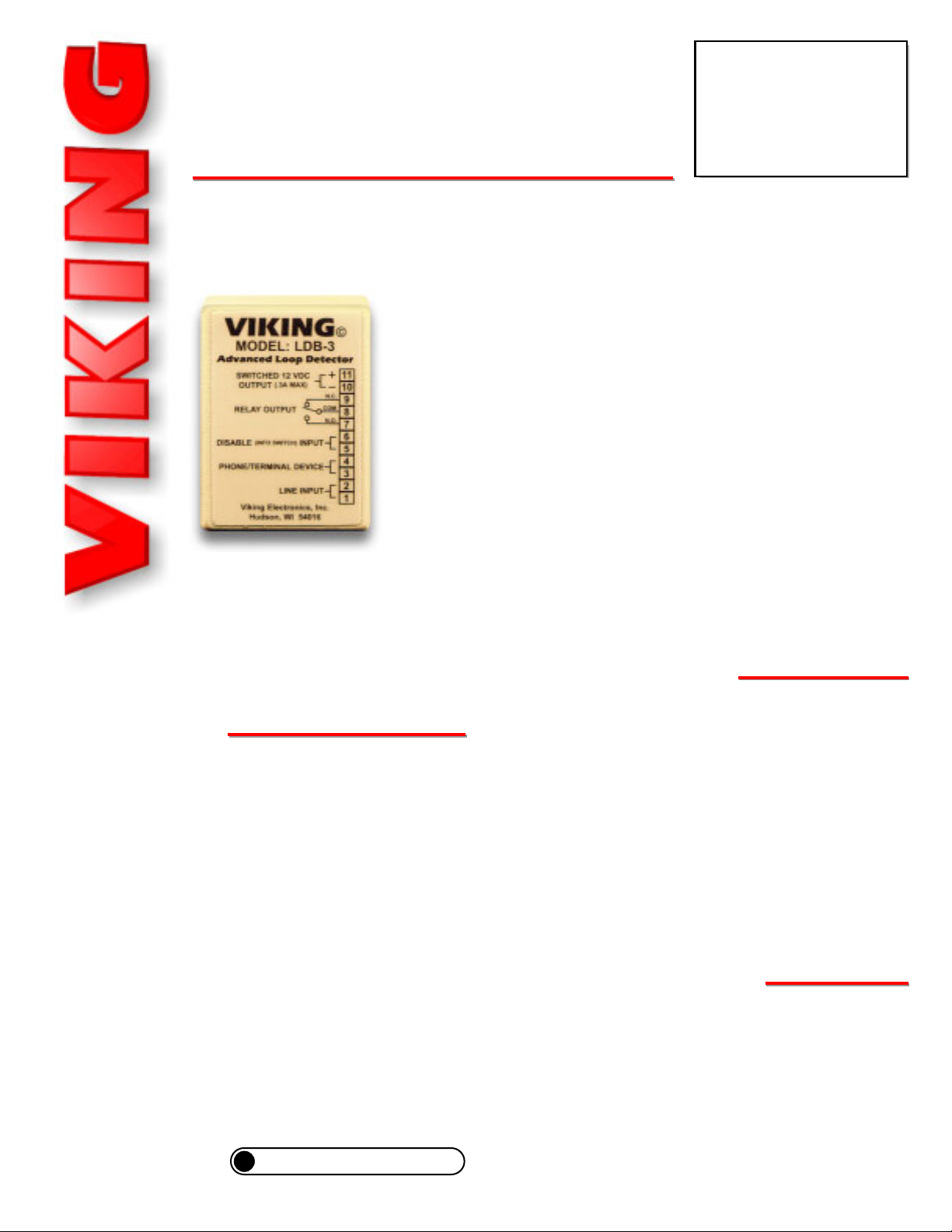
LDB-3
LDB-3
Advanced Ring/
Loop Detector
January 8, 2003
Ideal for Use with Two-Button Emergency Phones!
The LDB-3 Advanced Loop Detector monitors an analog phone line
for ringing and/or an off hook condition. A built-in relay can be activated when either of these conditions are detected. This is ideal for
monitoring line status or for providing a visual indication of such.
The LDB-3’s disable input is ideal for two-button emergency phones,
such as Viking’s E-1600-20A, allowing “Info” button calls to be
placed without activating the relay (turning on the emergency strobe
light, camera, etc.)
Three DIP switches are provided for turning ring detection on or off,
off-hook/loop detection on or off and for selecting a ring cadence
Provide a Contact Closure
During Ringing and/or Off-Hook
PPhhoonnee......771155..338866..8888661
1
hhttttpp::////wwwwww..vviikkiinnggeelleeccttrroonniiccss..ccoom
m
• Detects ring voltage and off hook loop current
• On/off switches for ring detection and offhook/loop detection
• Screw terminal connections
• Selectable ring cadence mode (relay can remain
on between rings)
• Wall mountable with foam tape (included) or
screws (not included)
• Switched 12V DC output (follows relay activation
for powering strobe lights, cameras, etc.)
• One set of (NO) normally open or (NC) normally
closed relay contacts provided
• Disable input, ideal for use with two-button
emergency phones (E-1600-20A), will not
activate relay on “Info” calls
Power: 120V AC to 12V DC adapter provided
Dimensions: 74mm x 53mm x 25mm (2.9” x 2.1” x 1.0”)
Shipping Weight: 0.4 kg (0.86 lbs)
Environmental: -26° C to 54° C (-15° F to 130° F) with 5% to
95% non-condensing humidity
Relay Contact Rating: .5A @ 125V AC/1A @ 30V DC
Maximum Current Draw Auxiliary 12V DC Output: 350mA
Minimum Loop Current: 15 mA
Disable/Info Switch Input: 50mA/80mW maximum
Ringer Equivalence: 0.5 A REN
Connections: 2 position and 11 position screw terminal blocks
PPrraaccttiicce
e
T
T
EELLEECCOOM
M
S
S
OOLLUUTTIIOONNSSFFOORRTTHHE
E
221
1
SST
T
C
C
EENNTTUURRY
Y
TECHNICAL
TECHNICAL
FFeeaattuurrees
s
SSppeecciiffiiccaattiioonns
s
?
Need More Information on the E-1600-20A?
Call (715) 386-4345 and select 215.
• Control a strobe or beacon light for ring indication
• Provide relay closures on off-hook
• Trigger a security camera
• Trigger a tape recorder
• Phone “In Use” indicator
AApppplliiccaattiioonns
s
Page 2
Z3
Z2
R4
R7
R9
R8
CR
IInnssttaallllaattiioon
n
A. Using Screws (not included)
B. Using the Included Tape
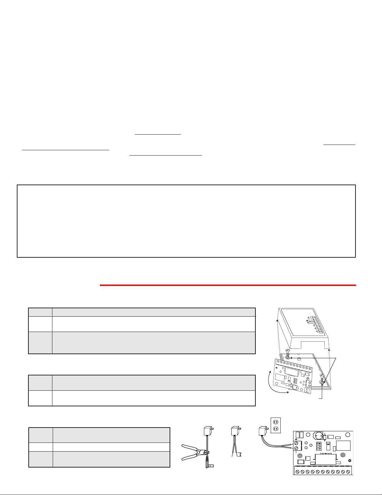
Step 1. Unsnap the plastic cover and remove the top screw holding the circuit board.
Step 2. Loosen the bottom screw and rotate the circuit board to the left, exposing the
two mounting holes in the base.
Step 3. Screw the base to the wall, etc. using (2) #6 flathead or sheetrock screws.
Note: Make sure the screw heads are fully driven into the base to avoid
shorting the circuit board leads.
Step 1. Clean the back of the LDB-3 and the surface you are mounting to with rubbing
alcohol before mounting.
Step 2. Remove the backing on one side of the tape and adhere to the LDB-3. Remove
the rest of the backing and press unit firmly to surface you are mounting to.
C. Preparing the Power Supply
Step 1. Cut off the barrel connector on the power
supply (see right).
Step 2. Separate and strip wires (see right).
Step 3. Connect to the screw terminal block on the
LDB-3, then plug in power supply (see right).
Z3
Z2
R8
CR
IF YOU HAVE APROBLEM WITH A VIKING PRODUCT, PLEASE CONTACT: VIKING TECHNICAL SUPPORT AT (715) 386-8666
Our Technical Support Department is available for assistance Monday 8am - 4pm, Tuesday-Friday 8am - 5pm central time. So that we can give you better service, before you call please:
1. Know the model number, the serial number and what software version you have (see serial label).
2. Have your Technical Practice in front of you.
3. It is best if you are on site.
WARRANTY
Viking warrants its products to be free from defects in the workmanship or materials, under normal use and service, for a period of one year from the date of purchase from any authorized Viking distributor
or 18 months from the date manufactured, which ever is greater. If at any time during the warranty period, the product is deemed defective or malfunctions, return the product to Viking Electronics, Inc., 1531
Industrial Street, Hudson, WI., 54016. Customer must contact Viking's Technical Support Department at 715-386-8666 to obtain a Return Authorization (R.A.) number.
This warranty does not cover any damage to the product due to lightning, over voltage, under voltage, accident, misuse, abuse, negligence or any damage caused by use of the product by the purchaser or
others.
Vikings sole responsibility shall be to repair or replace (at Viking's option) the material within the terms stated above. VIKING SHALLNOTBE LIABLE FOR ANYLOSS OR DAMAGE OF ANYKIND INCLUDING INCIDENTALOR CONSEQUENTIAL DAMAGES RESULTING DIRECTLYOR INDIRECTLY FROM ANY BREACH OF ANY WARRANTY EXPRESSED OR IMPLIED, OR FOR ANY OTHER FAILURE OF
THIS PRODUCT. Some states do not allow the exclusion or limitation of incidental or consequential damages, so this limitation may not apply to you.
THIS WARRANTY IS IN LIEU OF ALL OTHER WARRANTIES, EXPRESSED OR IMPLIED, INCLUDING THE WARRANTIES OF MERCHANTABILITY AND FITNESS FOR A PARTICULAR PURPOSE,
WHICH ARE HEREBY EXCLUDED BEYOND THE ONE YEAR DURATION OF THIS WARRANTY. Some states do not allow limitation on how long an implied warranty lasts, so the above limitation may not
apply to you.
RETURNING PRODUCT FOR EXCHANGE
The following procedure is for equipment that has failed out-of-box (within 10 days of purchase):
1. Customer must contact Viking’s Technical Support at 715-386-8666 to determine possible causes for the problem. The customer MUSTbe able to step through recommended tests for diagnosis.
2. If the Technical Support Product Specialist determines that the equipment is defective based on the customer's input and troubleshooting, a Return Authorization (R.A.) number will be issued. This number is valid
for fourteen (14) calendar days from the date of issue.
3. After obtaining the R.A. number, return the approved equipment to your distributor, referencing the R.A. number. Your distributor will then replace the product over the counter at no charge. The distributor will
then return the product to Viking using the same R.A. number.
4. The distributor will NOT exchange this product without first obtaining the R.A. number from you. If you haven't followed the steps listed in 1, 2 and 3, be aware that you will have to pay a
restocking charge.
RETURNING PRODUCT FOR REPAIR
The following procedure is for equipment that needs repair:
1. Customer must contact Viking's Technical Support Department at 715-386-8666 to obtain a Return Authorization (RA) number. The customer MUSThave a complete description of the problem, with all pertinent
information regarding the defect, such as options set, conditions, symptoms, methods to duplicate problem, frequency of failure, etc.
2. Packing: Return equipment in original box or in proper packing so that damage will not occur while in transit. Static sensitive equipment such as a circuit board should be in an anti-static bag, sandwiched between
foam and individually boxed. All equipment should be wrapped to avoid packing material lodging in or sticking to the equipment. Include ALLparts of the equipment. C.O.D. or freight collect shipments cannot be
accepted. Ship cartons prepaid to: Viking Electronics, 1531 Industrial Street, Hudson, WI 54016
3. Return shipping address: Be sure to include your return shipping address inside the box. We cannot ship to a PO Box.
4. RAnumber on carton: In large printing, write the R.A. number on the outside of each carton being returned.
Step 1. Step 2. Step 3.
IMPORTANT: Do NOT plug in the
adapter until after Step 3 is completed.
0.25"
Advanced Loop Detector
120V DC
(+) Black
(-) Black with
White Stripe
VIKING
MODEL: LDB-3
SWITCHED 12 VDC
DISABLE
R
5
Z3
4
R
R7
©
OUTPUT
RELAY OUTPUT
PHONE/TERMINAL DEVICE
R
2
C
9
R
11
(.3A MAX)
10
N.C.
9
COM
8
N.O.
7
INPUT
LINE INPUT
Viking Electronics, Inc.
Hudson, WI 54016
1 2 3 4 5 6 7 8 9 10 11
(2) #6 Flathead
Screws
6
5
4
3
2
1
Z2
R
2
(INFO SWITCH)
R
2
8
R
Z2
Screws or Sheetrock
1 2 3 4 5 6 7 8 9 10 11
Mounting
Holes
R4R4R7R7R9R9R8
Z3
CR
R
2
5
Page 3

C. Off-Hook/Loop Current Detection Only
1 2 3 4 5 6 7 8 9 10 11
Z3Z3
Z2Z2
R
5
R
2
R4R4
R7R7
R9R9
R8R8
CRCR
2
1
2
3
4
5
6
7
8
9
To C.O. Line or Analog
PABX/KSU extension
To Terminal Device/Phone
Disable/Info Switch Input
Relay Contacts
Switched 12VDC
(350mA maximum) Output
10
11
Normally Open
Common
Normally Closed
(+) Black
(-) Black with
White Stripe
120V DC
The LDB-3 must be placed between the phone line and
the terminal device (phone) to be monitored. Connect
the incoming line to positions 1 and 2 and connect the
terminal device (phone) to positions 3 and 4.
D. Ring and Off-Hook/Loop Current Detection
If the application requires off-hook (loop) and ring detection, the LDB-3 must be placed between the phone line
and the terminal device (phone) to be monitored.
Connect the incoming line to positions 1 and 2, connect
the terminal device (phone) to positions 3 and 4.
B. Ring Detection Only
Connect the incoming line to terminal block positions 1
and 2 as shown in the diagram. No terminal device
(phone) is required. In this manner, the LDB-3 can monitor for ringing any place along the ringing line.
A. DIP Switches
Sw 1
ON
OFF
ON
Sw 3
OFF
ON
ON
Description
Ring Detection Only (see section B)
Off-Hook/Loop Current Detection Only (see section C)
Ring and Off-Hook/Loop Current Detection (see section D)
Sw 2
ON
OFF
Ring Cadence Mode (see section E)
Ring Cadence Mode ON - relay remains activated in between rings.
Ring Cadence Mode OFF - relay is activated only during ringing.
PPrrooggrraammmmiinng
g
Z3
Z2
R8
CR
F. Relay Contacts
Normally open and normally closed relay contacts are available at terminal block positions 7, 8, 9. The contacts are
rated at .5A @ 125VAC/1A @ 30VDC. If contacts are driving an inductive load, place a suppression device at the load
to snub high voltage spikes.
G. Switched 12V DC Output
The switched 12V DC output is a low current, 12-15VDC output that is turned on only while the ring/loop detect relay
is activated. This switched power output is ideal for lighting strobe lights or powering up any device that draws less
than 350mAmps. The positive side is available at terminal position 11, and the negative side is at position 10. Once
all the line and load connections have been made, plug in the 115 V AC wall adapter, and replace the cover.
E. Ring Cadence Mode
DIP switch 2 is used for switching between different ring detection modes. In the OFF position, the relay and switched
12VDC output will activate only while ring voltage is present and will turn off between rings. In the ON position, the
relay and switched 12VDC output will remain on for up to 5.75 seconds after the ringing has stopped. This allows the
relay and 12VDC to remain on between rings of a standard ring cadence. Note: To use the Ring Cadence Mode, ring
detection MUST be enabled (DIP switch 1 - ON).
OFF ON
1
2
3
R4R4R7R7R9R9R8
Z2
2
1 2 3 4 5 6 7 8 9 10 11
Z3
CR
R
2
5
R
Page 4

Due to the dynamic nature of the product design, the information contained in this document is subject to change without notice. Viking Electronics, and its affiliates and/or
subsidiaries assume no responsibility for errors and omissions contained in this information. Revisions of this document or new editions of it may be issued to incorporate
such changes.
Fax Back Doc 409 ZF301620 Rev APrinted in the U.S.A.
PPrroodduuccttSSuuppppoorrttLLiinnee......771155..338866..8866666
6
FFaaxxBBaacckkLLiinnee......771155..338866..4433445
5
H. Disable Feature
By connecting the Disable/Info Switch input of the LDB-3 to the
“Info” switch of Viking’s E-1600-20A, E-1600-20A-EWP, E-1600-
52A or E-1600-52A-EWP Emergency Phone (not included), any
outbound calls initiated from the “Info” button will not activate the
loop detect relay. This way, only the “Help/Emergency” outbound
calls will activate the relay. Cut one of the “Info” switch wires in
half and connect each end to LDB-3 terminals 5 and 6 as shown
in the diagram at the right.
Note: The Disable input is NOT polarity sensitive.
The “Disable” input can be connected to a remote switch, contact closure, etc. for deactivating the LDB-3’s internal
relay.
Z3
Z2
R4
R7
R9
R8
CR
OOtthheerrPPrroodduucctts
s
BLK-3-EWP Strobe Light Kit
The BLK-3-EWP can be used to add emergency notification to pre-installed emergency phones. The
BLK-3-EWP is equipped with Enhanced Weather Protection (EWP) and will not flash on “Info” calls
when used with the E-1600-20A or E-1600-52A. Alternatively, the BLK-3-EWP provides high visibility indication of analog line status through a high powered strobe light. The BLK-3-EWP is an ideal
solution for the hearing impaired and can be used equally well in loud warehouses or factories,
where ringing phones can not be heard.
?
Need More Information on the BLK-3-EWP?
Call (715) 386-4345 and select 653.
ADA Compliant Emergency Phones
The 1600A Series ADA Compliant Emergency Phones are designed to provide quick and reliable handsfree communication for any standard analog telephone line or analog phone system station port. All 1600A Series phones
meet ADA requirements for elevator/ emergency telephones, and can be
programmed from any Touch Tone phone. The phones can dial up to 5
programmable emergency numbers, as well as 2 central station
numbers. In addition, the E-1600-20A and E-1600-52A feature
a second "Info" button that will dial up to 3 non-emergency numbers.
The 1600A Series phones can be programmed to automatically
deliver a digital announcement to identify the location of the
emergency call. Alternatively, a DTMF Touch Tone code may
also be delivered. A “Call Connected” LED can be initiated manually or automatically. All programming parameters are stored in non-volatile memory. All units are phone line powered,
requiring no batteries or external power and are compatible with common Central Station Monitoring equipment.
For outdoor or harsh environments, select 1600A Series phones are available with Enhanced Weather Protection (EWP).
EWP products feature rubber gaskets and boots, hand soldered silicon sealed connections, gel filled tip and ring connectors, as well as urethane potted circuit boards with weather sealed, field-adjustable trim
pots and DIP switches for easy on-site programming.
?
Need More Information on the 1600A Series?
Call (715) 386-4345 and select 215.
Z3
Z2
R4
R7
R9
R8
CR
This can be useful to turn off the controlled device (strobe light,
camera, etc.) Use the diagram shown at the right.
If the relay has been activated by ringing, the switch
will deactivate the relay and ringing must stop for a
minimum of 6 seconds before the relay can be reactivated from a new incoming call.
?
Need More Information on EWP?
Call (715) 386-4345 and select 859.
Rear View of E-1600-20A
Model: xxxxxxx
P/N: xxxxxxx
S/N: XXXXXX
Viking Electronics, Inc. (715)386-8861
1531 Industrial St., Hudson, WI 54016
VIKING
390 Ohm - 750 Ohm, 1/2 Watt Resistor
(Radio Shack part # 271-1114, 271-1115,
271-1116, 271-1117 or equivalent)
LDB-3
1 2 3 4 5 6 7 8 9 10 11
Z2
2
R
R8
2
R9
CR
R7
R4
5
R
Z3
1 2 3 4 5 6 7 8 9 10 11
Z2
2
R
R8
2
R9
CR
R7
R4
5
R
Z3
 Loading...