

Viking FDFB5301R, FDFB5361R, FDRB5301R, FDRB5361R, FDSB5421 Installation Manual
...
Viking Range Corporation
111 Front Street
Greenwood, Mississippi 38930 USA
(662) 455-1200
For product information,
call 1-888-VIKING1 (845-4641)
or visit the Viking Web site at
vikingrange.com
F20844 EN
(012512)
Viking Installation Guide
Custom Panel Models
All Refrigerator/Freezer/
Side-by-Side/Bottom-Mount
U
L
C
U
L
3
2
Table of Contents
W
arnings & Important Information ____________________________________________________________________3
Bottom-Mount
Dimensions and Specifications (36”) __________________________________________________________6
Cutout Dimensions (36”) ____________________________________________________________________8
Anti-Tip Dimensions (36”) ___________________________________________________________________9
Overlay Dimensions (36”) __________________________________________________________________10
Custom Grille Dimensions (36”) _____________________________________________________________11
Side-By-Side
Dimensions (42”) _________________________________________________________________________13
Dimensions (48”) ________________________________________________________________________14
Specifications (42” and 48”) ________________________________________________________________15
Cutout Dimensions (42”) __________________________________________________________________16
Anti-Tip Dimensions (42”) _________________________________________________________________17
Cutout Dimensions (48”)___________________________________________________________________18
Anti-Tip Dimensions (48”)__________________________________________________________________19
Overlay Dimensions (42”) __________________________________________________________________20
Overlay Dimensions (48”) __________________________________________________________________21
Custom Grille Dimensions (42”) ____________________________________________________________22
Custom Grille Dimensions (48”) ____________________________________________________________23
All Refrigerator/Freezer
Dimensions & Specifications (30” and 36”) ___________________________________________________24
Cutout Dimensions (30”)___________________________________________________________________26
Anti-Tip Dimensions (30”)__________________________________________________________________27
Cutout Dimensions (36”)___________________________________________________________________28
Anti-Tip Dimensions (36”)__________________________________________________________________29
Dimensions (Dual 30”)_____________________________________________________________________30
Dimensions (Dual 30” and 36”) _____________________________________________________________31
Dimensions (Dual 36”)_____________________________________________________________________32
Specifications (Dual) _______________________________________________________________________33
Cutout Dimensions (Dual 30”) ______________________________________________________________34
Anti-Tip Dimensions (Dual 30”) _____________________________________________________________35
Cutout Dimensions (Dual 30” and36”) ______________________________________________________36
Anti-Tip Dimensions (Dual 30” and 36”) _____________________________________________________37
Cutout Dimensions (Dual 36”) ______________________________________________________________38
Anti-Tip Dimensions (Dual 36”) _____________________________________________________________39
Overlay Dimensions (30” & 36”) ____________________________________________________________40
Custom Grille Dimensions (30”) _____________________________________________________________41
Custom Grille Dimensions (36”) _____________________________________________________________42
Custom Grille Dimensions (Dual 30”)________________________________________________________43
Custom Grille Dimensions (Dual 30” and 36”) ________________________________________________44
Custom Grille Dimensions (Dual 36”)________________________________________________________45
Cabinet Information _______________________________________________________________________________46
Custom Side Panel Dimensions _____________________________________________________________________48
Custom Panel General Information __________________________________________________________________49
Ice and Water Dispenser Bezel Removal ______________________________________________________________49
Custom Door Panel Installation – (Refrigerator or Freezer) ______________________________________________51
Ice and Water Dispenser Bezel Installation ____________________________________________________________54
Door Trim Insert___________________________________________________________________________________55
Custom Panel Hinge Cutout ________________________________________________________________________56
Custom Grille Installation___________________________________________________________________________56
General Information _______________________________________________________________________________58
Unpacking & Moving ______________________________________________________________________60
Installation________________________________________________________________________________________61
Hinge Adjustment _________________________________________________________________________62
Kickplate Installation_______________________________________________________________________64
Door Stop Adjustment_____________________________________________________________________65
Water Filter Installation ____________________________________________________________________66
Water Filter System Specifications___________________________________________________________67
Final Installation __________________________________________________________________________68
Performance Checklist _____________________________________________________________________________69
Control Panels ____________________________________________________________________________________70
Service & Registration______________________________________________________________________________72
IMPORTANT – Please Read and Follow
• Make sure that incoming voltage is the same as
unit rating. An electricrating plate specifying
voltage, frequency, wattage, amperage, and
phase is attached to the product.
• To reduce the risk of fire, electrical shock, or injury
to persons, installation work and electrical wiring
must be done by a qualified technician in
accordance with all applicable codes and
standards, including fire-rated construction.
• The installershould leave these instructionswith
the consumer who should retain them for local
inspector’s use and for future reference.
It is your responsibility to:
• Comply with installation specifications and
dimensions.
• Properly install unit.
• Remove any moldings or decorative panels that
prevent the unit from being serviced.
• Make sure that you have these materials (not
providedwith your unit), which are necessary for
proper installation:
• 1/4” (6 mm) copper tubing with shutoff valve
• 6 – #8 x 3” (7.6 cm) wood screws (longer
screws may be required)
• 1– Saddle valve (DO NOT use self-piercing
feature of the valve)
• Assure that floor will support unit, door panels
and contents (approximately 1200 pounds
[540 kg]).
• Provide a properly grounded electricaloutlet.
• Assure that locationwill permit appliance doors
to open a minimum of 90˚.
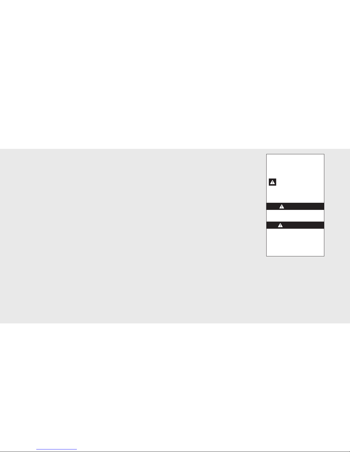
Your safety and the safety of others is
very important.
We have provided many important safety
messages in this manual and on your
appliance. ALWAYS read and obey all
safety messages.
This is the safety alert symbol. This
symbol alerts you to hazards that
can kill or hurt you and others.
All safety messages will be preceded
by the safety alert symbol and the word
“DANGER” or “WARNING.”
These words mean:
Hazards or unsafe practices
which WILL result in severe personal
injury or death
DANGER
Hazards or unsafe practices
which COULD result in severe personal
injury or death
All safety messages will identify the
hazard, tell you how to reduce the chance
of injury, and tell you what can happen if
the instructions are not followed.
WARNING
5
IMPORTANT–Please Read and Follow!
4
A GFI shall be used if required by NFPA-70 (National Electric Code), federal/state/local
laws, or local ordinances.
• The required use of a GFI is normally related to the location of a receptacle with respect to
any significant sources of water or moisture.
• Viking Range Corporation will NOT warranty any problems resulting from GFI outlets which
are not installed properly or do not meet the requirements below.
If the use of a GFI is required, it should be:
• Of the receptacle type (breaker type or portable type NOT recommended)
• Used with permanent wiring only (temporary or portable wiring NOT recommended)
• On a dedicated circuit (no other receptacles, switches or loads in the circuit)
• Connected to a standard breaker of appropriate size (GFI breaker of the same size NOT
recommended)
• Rated for Class A (5 mA +/- 1 mA trip current) as per UL 943 standard)
• In good condition and free from any loose-fitting gaskets (if applicable in outdoor situations)
• Protected from moisture (water, steam, high humidity) as much as reasonably possible
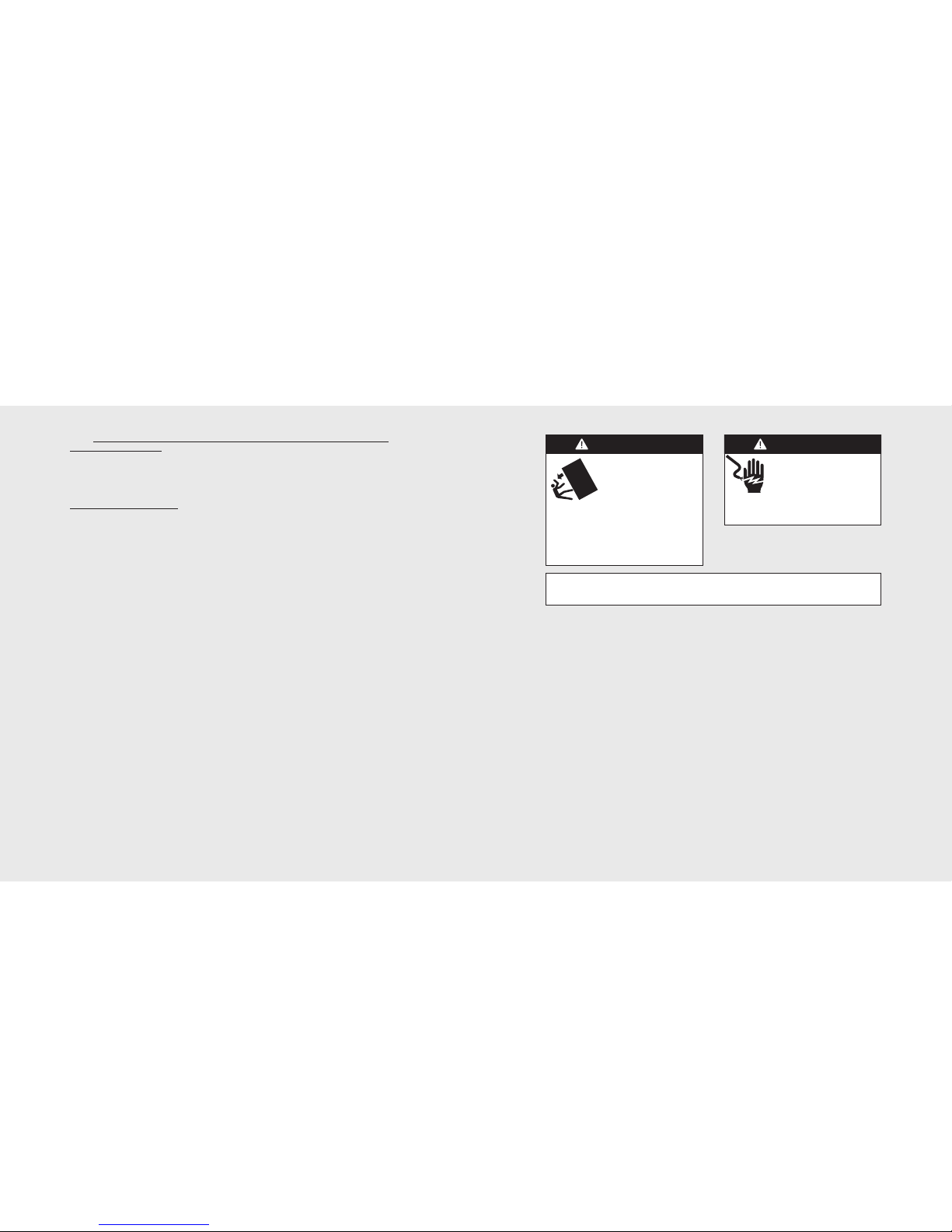
ELECTRICAL SHOCK
HAZARD
Disconnect power or turn
power disconnect switch to
OFF position before removing top grille.
Failure to do so can result in death or
electric shock.
WARNING
WARNING
TIP OVER HAZARD
Appliance is top heavy
and tips easily when not
completely installed. Keep
doors closed until appliance
is completely installed and secured per
installation instructions.
Use two or more people to move and
install appliance. Failure to do so can
result in death or serious injury.
Most of the unit’s weight is at the top. Extra care is needed when moving the unit to prevent
tipping. Use cardboard shipping material or plywood under unit until it is installed in the
operating position to protect floor surface.
Specifications (Bottom-Mount)
51-
7/
8”
(
1
3
1
.
8
c
m
)
23-
1/
16”
(
5
8
.
6
c
m
)
3-
1/
2”
(
8
.
9
c
m
)
82-
7/
8”
(
2
1
0
.
5
c
m
)
m
i
n
.
t
o
84-
1/
16”
(
2
1
3
.
5
c
m
)
m
a
x
.
Me
a
s
u
r
e
m
e
n
t
v
a
r
i
e
s
(
l
o
c
a
l
l
y
s
u
p
p
l
i
e
d h
a
r
d
w
a
r
e
)
2
3
-
1
3
/
1
6
”
(
6
0
.
5
c
m
)
2
4
-
3
/
4
”
(
6
2
.
9
c
m
)
3
5
”
(
8
8
.
9
c
m
)
3
6
”
(
9
1
.
4
c
m
)
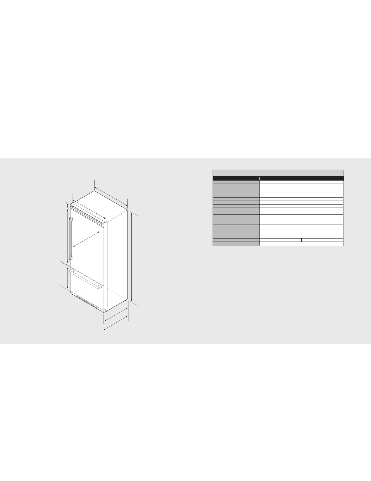
Dimensions (Bottom-Mount)
7
6
36” Bottom-Mount
Description FDBB5361
Overall width 36” (91.5 cm)
Overall height (from bottom) 82-3/4” (210.2 cm) min. to84-1/16” (213.5 cm) max.
Overall depth (from rear) To front edge of side trim:23-13/16” (60.5 cm)
To front of top grille: 24-3/4”(62.9 cm)
To front edge of door trim:24” (61.0 cm)
Cutout width 36” (91.5 cm)
Cutout height 82-7/8” (210.5 cm) min. to84-1/16” (213.5 cm) max.
Cutout depth 24” (61.0 cm) min.*
Electrical requirements 115 volt, 60 Hz, 15amp dedicated circuit; 3-wirecord with
grounded 3-prong plug attached to product
Maximum amp usage 9.9 amps
Inlet water requirements 1/4” copper tubing inlet waterline; minimum20 psi;
maximum 120 psi
Overall interior dimensions
Refrigerator 15.3 cu. ft. (434liters)
Freezer 5.1 cu. ft. (145 liters)
Total capacity 20.4 cu. ft. (579 liters)
Maximum panel weight Fresh food 45 lbs. (20.4 kg) Freezer 20 lbs. (9.0 kg)
Approximate shipping weight 500 lbs. (227.3 kg)
*Note: Custompanel models fit flush in 25” (63.5 cm) deep cabinet openings. They can be installed in standard
24” (61.0 cm) deep openings. The door faces and top grille will protrude 3/4” (1.9 cm) into the room.
36” Bottom-Mount
9
8
9
”
(
22
.
9 c
m
)
7
3
-
3
/
8
”
(18
6.
4
c
m
)
8
2-
7
/
8
”
(
2
1
0
.
5
c
m
)
m
i
n
.
a
n
t
i
-
t
i
p
b
o
a
r
d
&
o
p
e
n
i
n
g
h
e
i
g
h
t
8
4
-
1
/
1
6
”
(
2
1
3
.
5
c
m
)
m
a
x
.
a
n
t
i
-
t
i
p
b
o
a
r
d
&
o
p
e
n
i
n
g
h
e
i
g
h
t
3
6
”
(
9
1
.
5
c
m
)
2
4
”
(
6
1
.
0
c
m
)
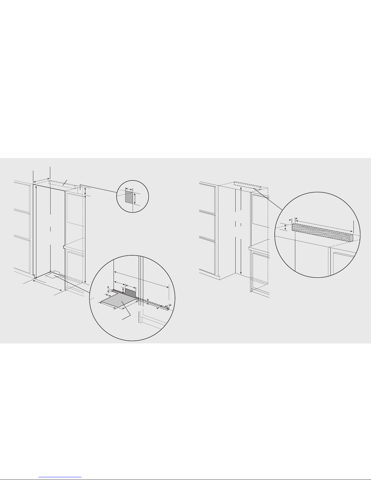
Electric Outlet Location
Water Line Entry Area
3
6
”
(
9
1
.
5
c
m
)
6
-
3
/
4
”
(
1
7
.
1
c
m
)
7
-
5
/
8
”
(
1
9
.
4
c
m
)
3
”
(
7
.
6
c
m
)
5
/
8
”
(
1
.
5
c
m
)
5
/
8
”
(
1
.
5
c
m
)
1
0
-
1
/
2
”
(
2
6
.
7
c
m
)
5
/
8
”
(
1
.
5
c
m
)
1
0
-
3
/
4
”
(
2
7
.
3
c
m
)
1
”
(
2
.
5
c
m
)
3
-
5
/
8
”
(
9
.
2
c
m
)
O
p
t
i
o
n
a
l
f
l
o
o
r
w
a
t
e
r
l
i
n
e
e
n
t
r
y
S
e
e
a
n
t
i
-
t
i
p
b
o
a
r
d
i
n
s
t
a
l
l
a
t
i
o
n
6
”
(
1
5
.
2
c
m
)
9
”
(
2
2
.
9
c
m
)
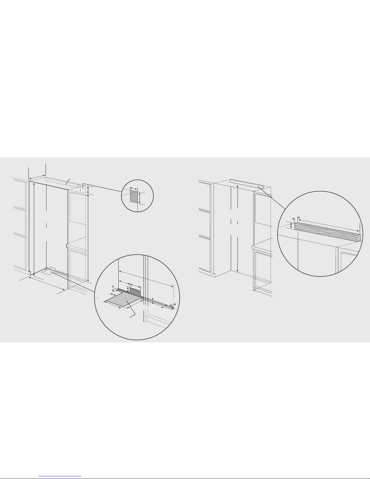
Cutout Dimensions (Bottom-Mount)
36” Bottom-Mount
One 2”x 4” mounting board
1-1/2” (3.8 cm) x 3-1/2” (8.9 cm)
Note: If unit is installed deeper than 24” (61.0 cm),
then shim behind the mounting board by the difference.
Note: Top of unit must be placed firmly under anti-tip board.
Bottom of anti-tip board is 3-7/8” (9.8 cm) below opening height.
Anti-Tip Location
7
9-
3
/
8
”
(
2
0
1
.
6
c
m
)
m
i
n
.
t
o
b
o
t
t
o
m
o
f
a
n
t
i
-
t
i
p
b
o
a
r
d
8
0-
1
/
2
”
(
2
0
4
.
6
c
m
)
m
a
x.
t
o
b
o
t
t
o
m
o
f
a
n
t
i
-
t
i
p
b
o
a
r
d
2
9
”
(
7
3
.
7
c
m
)
3
-
1
/
2
”
(
8
.
9
c
m
)
1
-1
/
2
”
(
3
.
8
c
m
)
Anti-Tip Dimensions
(Bottom-Mount)
36” Bottom-Mount
One 2”x4” mounting board 1-1/2” (3.8 cm) x 3-1/2” (8.9 cm)
Note: If unit is installed deeper than 24” (61.0 cm), then
shim behind the mounting board by the difference.
Bottom of anti-tip board is 3-7/8” (9.8 cm) below the opening height.
Note: Top of unit must be placed firmly under anti-tip board.
Reverse dimensions
for other end.
1
/
2
”
(
1
.
2
7
c
m
)
1
-
1
/
2
”
(
3
.
8
1
c
m
)
1
/
4
”
R
a
d
i
us
(
.
6
4
c
m
)
2
-
3
/
4
”
(
6
.
9
8
c
m
)
1
/
2
”
(
1
.
2
7
c
m
)
3
/
4
”
(
1
.
9
0
c
m
)
1
/
2
”
(
1
.
2
7
c
m
)
1
/
8
”
(
.
3
1
c
m
)
1
/
2
”
(
1
.
2
7
c
m
)
1
/
4
”
R
a
d
i
u
s
1/4” Radius
(
1
.
2
c
m
)
(1.2 cm)
1
/
4
”
R
a
d
i
u
s
(
.
6
4
c
m
)
7
/
8
”
(
2
.
2
2
c
m
)
1
/
2
”
(
1
.
2
7
c
m
)
3
4
”
(
8
6
.
3
6
c
m
)
3
4
”
(
8
6
.
3
6
c
m
)
3
/
4
”
(
1
.
9
0
c
m
)
1
/
2
”
(
1
.
2
7
c
m
)
3
/
4
”
(
1
.
9
0
c
m
)
3
-
3
/
4
”
(
9
.
5
2
c
m
)
3
-
3
/
4
”
(
9
.
5
2
c
m
)
3
-
5
/
8
”
(
9
.
2
0
c
m
)
3
3
-
1
5
/
1
6
”
(
8
6
.
2
0
c
m
)
3
”
(
7
.
6
2
c
m
)
3
”
(
7
.
6
2
c
m
)
3
/
4
”
(
1
.
9
0
c
m
)
3
5
-
1
/
2
”
(
9
0
.
1
7
c
m
)
1
/
2
”
(
1
.
2
7
c
m
)
3
-
1
/
8
”
(
7
.
9
3
c
m
)
O
p
t
i
o
n
a
l
h
i
n
g
e
c
o
v
e
r
3
2
-
3
/
1
6
”
(
8
1
.
7
5
c
m
)
5
-
1
7
/
3
2
”
(
1
4
.
1
0
c
m
)
4
-
1
1
/
6
4
”
(
1
0
.
5
9
c
m
)
3
0
-
2
7
/
3
2
”
(
7
8
.
3
4
c
m
)
3
-
2
5
/
3
2
”
(
9
.
6
0
c
m
)
2
7
/
3
2
”
(
.
8
4
c
m
)
9
/1
6
”
(
1
.
4
2
c
m
)
1
/
4
”
(
.
6
3
5
c
m
)
1
6
.
5
˚
2
0
.
0
˚
2
-
1
/
8
”
(
5
.
4
c
m
)
Custom Grille Dimensions (Bottom-Mount)
3
5
-
1
/
4
”
(
8
9
.
5
c
m
)
23-
1/
16”
(
5
8
.
6
c
m
)
3/
4”
(
1
.
9
c
m
)
3
5
-
1
/
4
”
(
8
9
.
5
c
m
)
3
2
-
1
/
4
”
t
o
n
o
t
c
h
(
8
1
.
9
c
m
)
5
/
8
”
(
1
.
6
c
m
)
51-
7/
8”
(
1
3
1
.
8
c
m
)
51-
1/
4”
(
1
3
0
.
2
c
m
)
3/
4”
(
1
.
9
c
m
)
N
o
t
e:
C
o
r
n
e
r
n
o
t
c
h
i
s
f
o
r
l
e
f
t
h
i
n
g
e
d
o
o
r
.
R
e
v
e
r
s
e
f
o
r
r
i
g
h
t
h
i
n
g
e
.
S
e
e
p
a
g
e
5
4
f
o
r
c
u
t
o
u
t
i
n
s
t
r
u
c
t
i
o
n
s
.
1-
13/
16”
(
4
.
60
c
m
)
5/
8”
5/8”
(
1.
6
c
m
)(1.6 cm)
3”
(
7
.
6
2
c
m
)
3/
32”
(
.
2
4
c
m
)
5/8”
5/
8”
(
1.
6
c
m
)
Note: Inset shown
upside down.
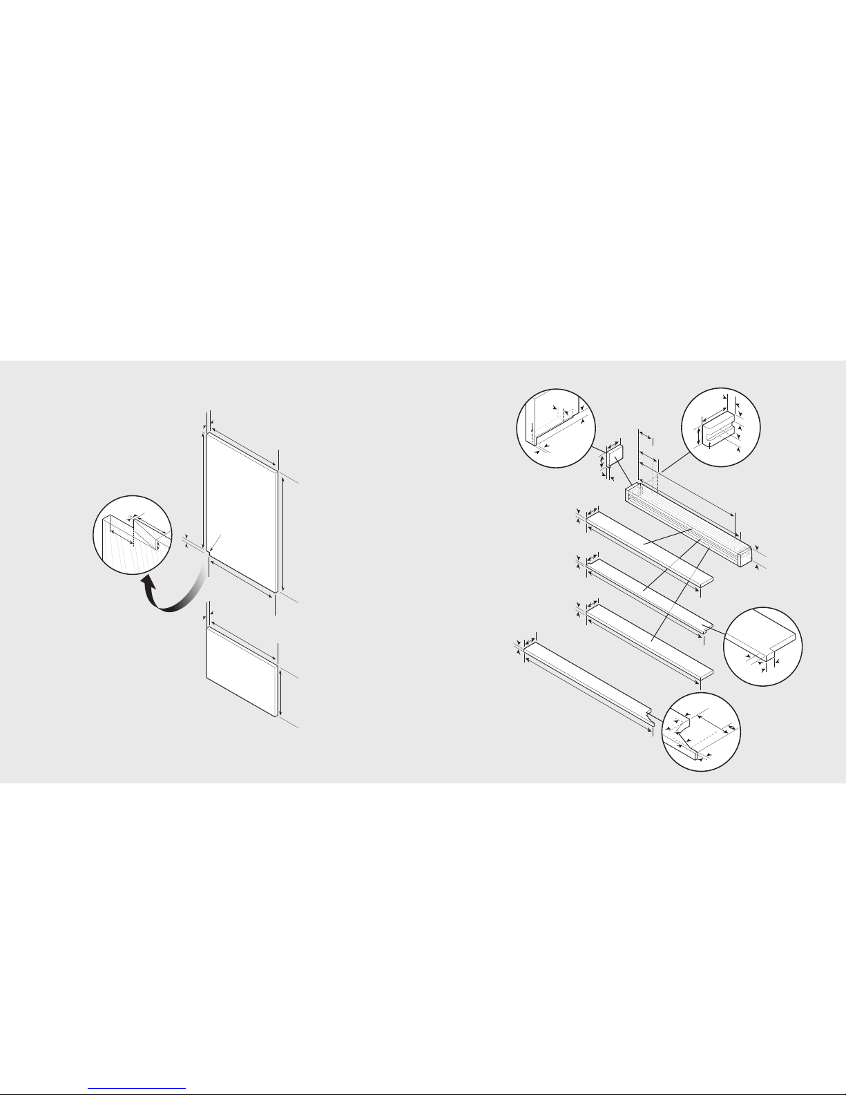
Overlay Dimensions (Bottom-Mount)
11
10
36” Custom Panels 36” Custom Grille
Note: Panel overlays must be dry, solid, straight
one-piece panels. The use of multiple panel
pieces to achieve the dimensions is not
recommended. Note: Optional hinge cover can be attached
using a strong VHB tape, countersunk wood
screws or short nails from a nail gun.
Dimensions (Side-By-Side)
3
2
5
/
3
2
”
(
9
.
6
0
c
m
)
2
7
/
3
2
”
(
.
8
4
c
m
)
9
/1
6
”
(
1
.
4
2
c
m
)
1
/
4
”
(
.
6
3
5
c
m
)
1
6
.
5
˚
2
0
.
0
˚
Note: This part should be
located at the center of the
grille. If desired, two per grille
can be used by dividing the
length of the grille into thirds.
1
/
2
”
(
1
.
2
7
c
m
)
1
-
1
/
2
”
(
3
.
8
1
c
m
)
1
/
4
”
R
a
d
i
u
s
(
.
6
4
c
m
)
2
-
3
/
4
”
(
6
.
9
8
c
m
)
1
/
2
”
(
1
.
2
7
c
m
)
3
/
4
”
(
1
.
9
0
c
m
)
3/8”
(
0.38 cm)
1/2”
(1.27 cm)
R 3/32”
(0.09 cm)
3/4”
(1.90 cm)
3/4”
(
1.90 cm)
3/4”
(
1.90 cm)
13/32”
(1.03 cm)
9/16”
(1.43 cm)
1/8”
(.32 cm)
Grille support
2
-
7
/
8
”
(
7
.
3
0
c
m
)
1
”
(
2
.
5
4
c
m
)
1
/
2
”
(
1
.
2
7
c
m
)
1
/
8
”
(
.
3
1
c
m
)
1
/
2
”
(
1
.
2
7
c
m
)
1
/
4
”
R
a
d
i
u
s1/4” Radius
(
1
.
2
c
m
)
(1.2 cm)
1
/
4
”
R
a
d
i
u
s
(
.
6
4
c
m
)
Reverse dimensions
for other end.
7
/
8
”
(
2
.
2
2
c
m
)
1
/
2
”
(
1
.
2
7
c
m
)
1
/
2
”
(
1
.
2
7
c
m
)
3
-
1
/
8
”
(
7
.
9
3
c
m
)
O
p
t
i
o
n
a
l
h
i
n
g
e
c
o
v
e
r
1
/
2
”
(
1
.
2
7
c
m
)
3
-
5
/
8
”
(
9
.
2
0
c
m
)
3
/
4
”
(
1
.
9
0
c
m
)
3
/
4
”
(
1
.
9
0
c
m
)
3
-
3
/
4
”
(
9
.
5
2
c
m
)
3
-
3
/
4
”
(
9
.
5
2
c
m
)
3
”
(
7
.
6
2
c
m
)
3
”
(
7
.
6
2
c
m
)
3
/
4
”
(
1
.
9
0
c
m
)
7
1
-
1
/
2
”
(
1
8
1
.
6
1
c
m
)
7
0
”
(
1
7
7
.
8
0
c
m
6
9
-
1
5
/
1
6
”
(
1
7
7
.
6
4
c
m
)
7
0
”
(
1
7
7
.
8
0
c
m
)
6
8
-
3
/
6
4
”
(
1
7
2
.
8
3
c
m
)
6
6
-
2
7
/
3
2
”
(
1
6
9
.
7
8
c
m
)
4
-
1
1
/
6
4
”
(
1
1
.
2
7
c
m
)
5
-
1
7
/
3
2
”
(
1
4
.
0
4
c
m
)
3
0
-
2
7
/
3
2
”
(
7
8
.
3
4
c
m
)
3
2
-
3
/
1
6
”
(
8
1
.
7
5
c
m
)
4
0
-
1
1
/
6
4
”
(
1
0
2
.
0
3
c
m
)
4
1
-
2
5
/
6
4
”
(
1
0 5
.
1
3
c
m
)
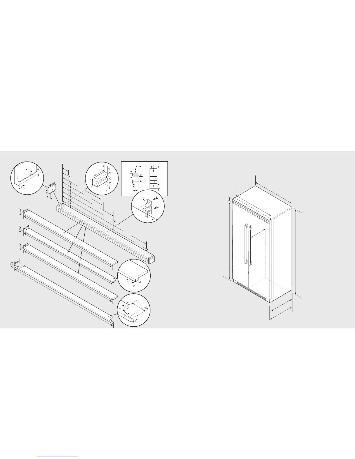
Custom Grille Dimensions (Bottom-Mount)
13
12
Dual 36” Custom Grille
42” Side-By-Side
75-
15/
16”
(
1
9
2
.
9
c
m
)
3-
1/
2”
(
8
.
9
c
m
)
8
2
-
7
/
8
”
(
2
1
0
.
5
c
m
)
m
i
n
.
t
o
8
4
-
1
/
1
6
”
(
2
1
3
.
5
c
m
)
m
a
x
.
M
e
a
s
u
r
e
m
e
n
t
v
a
r
i
e
s
(
l
o
c
a
l
l
y
s
u
p
p
l
i
e
d
h
a
r
d
w
a
r
e
)
2
3
-
1
3
/
1
6
”
(
6
0
.
5
c
m
)
2
4
-
3
/
4
”
(
6
2
.
9
c
m
)
4
1
”
(
1
0
4
.
1
c
m
)
4
2
”
(
1
0
6
.
7
c
m
)
Note: Optional hinge cover can be attached
using a strong VHB tape, countersunk wood
screws or short nails from a nail gun.
Specifications (Side-By-Side)
75-
15/
16”
(
1
9
2
.
9
c
m
)
3-
1/
2”
(
8
.
9
c
m
)
82-
7/
8”
(
2
1
0
.
5
c
m
)
m
i
n
.
t
o
84-
1/
16”
(
2
1
3
.
5
c
m
)
m
a
x
.
2
3
-
1
3
/
1
6
”
(
6
0
.
5
c
m
)
2
4
-
3
/
4
”
(
6
2
.
9
c
m
)
4
7
”
(
1
1
9
.
4
c
m
)
4
8
”
(
1
2
1
.
9
c
m
)
M
e
a
s
u
r
e
m
e
n
t
v
a
r
i
e
s
(
l
o
c
a
l
l
y
s
u
p
p
l
i
e
d
h
a
r
d
w
a
re
)
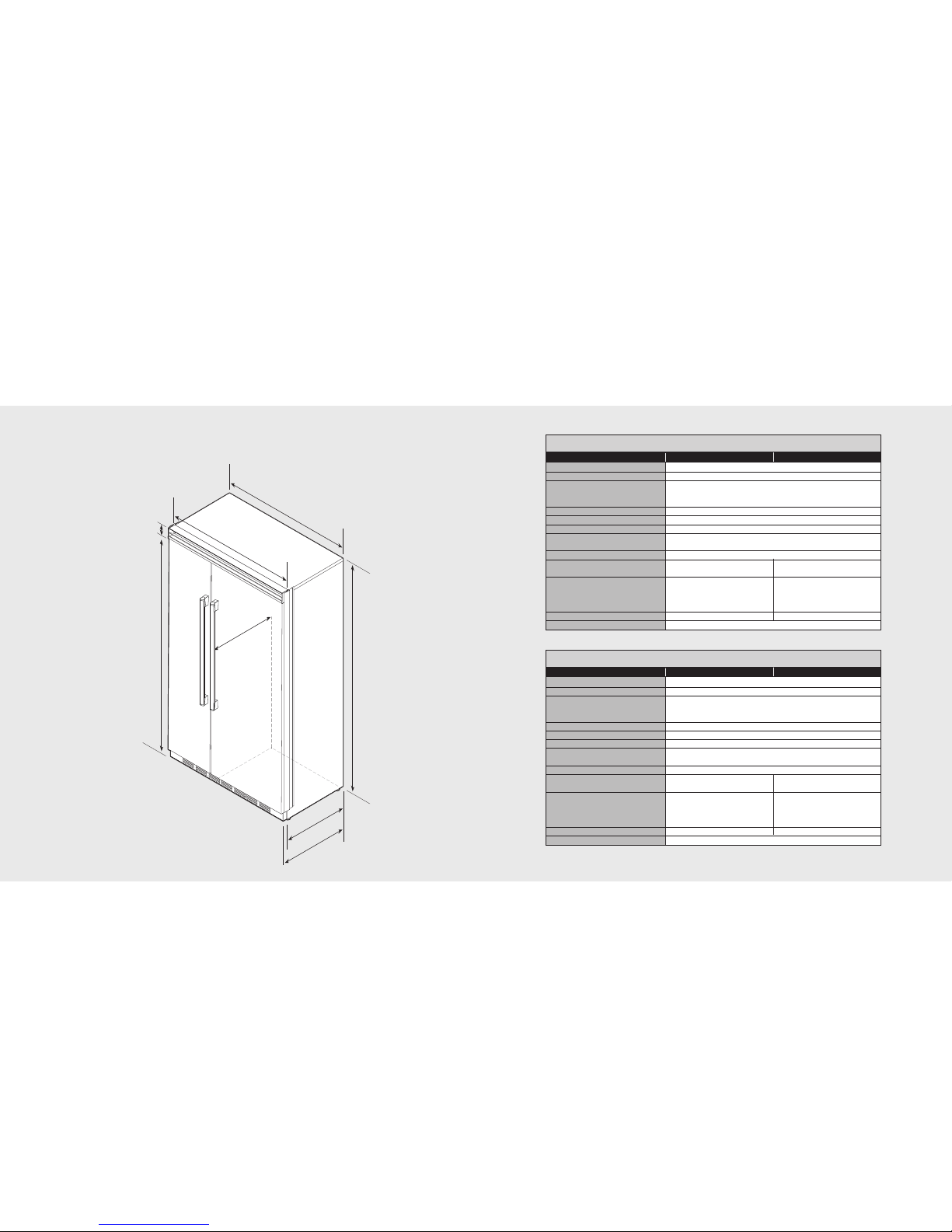
Dimensions (Side-By-Side)
15
14
42” Side-By-Side
Description FDSB5421 FDSB5421D
Overall width 42” (106.7 cm)
Overall height (from bottom) 82-3/4” (210.2 cm) min. to84-1/16” (213.5 cm) max.
Overall depth (from rear) To front edge of side trim:23-13/16” (60.5 cm)
To front of top grille: 24-3/4”(62.9 cm)
To front edge of door trim:24” (61.0 cm)*
Cutout width 42” (106.7 cm)
Cutout height 82-7/8” (210.5 cm) min. to84-1/16” (213.5 cm) max.
Cutout depth 24” (61.0 cm) min.*
Electrical requirements 115 volt, 60 Hz, 15amp dedicated circuit; 3-wirecord with
grounded 3-prong plug attached to product
Maximum amp usage 9.9 amps
Inlet water requirements
1/4” copper tubing inlet waterline; 1/4” copper tubing inlet waterline;
minimum 20 psi; maximum 120psi minimum 35 psi; maximum 120psi
Overall interior dimensions
Refrigerator 15.0 cu. ft. (425 liters) 15.0 cu. ft. (425 liters)
Freezer 9.0 cu. ft. (255liters) 8.9 cu. ft. (252 liters)
Total capacity 24.0 cu. ft. (680 liters) 23.9 cu. ft. (677 liters)
Maximum panel weight Fresh food 40 lbs. (18.1 kg) Freezer 35 lbs. (15.9 kg)
Approximate shipping weight 525 lbs. (236.2 kg)
48” Side-By-Side
Description FDSB5481 FDSB5481D
Overall width 48” (121.9 cm)
Overall height (from bottom) 82-3/4”(210.2 cm) min. to 84-1/16” (213.5 cm) max.
Overall depth (from rear) To front edge of side trim:23-13/16” (60.5 cm)
To front of top grille: 24-3/4”(62.9 cm)
To front edge of door trim: 24” (61.0 cm)*
Cutout width 48” (121.9 cm)
Cutout height 82-7/8” (210.5 cm) min. to.84-1/16” (213.5 cm) max
Cutout depth 24” (61.0 cm) min.*
Electrical requirements 115 volt, 60 Hz, 15amp dedicated circuit; 3-wirecord with
grounded 3-prong plug attached to product
Maximum amp usage 9.9 amps
Inlet water
requirements 1/4” copper tubing inlet waterline; 1/4” copper tubing inlet waterline;
minimum 20 psi; maximum 120psi minimum 35 psi; maximum120 psi
Overall interior dimensions
Refrigerator 18.5 cu. ft. (524 liters) 18.5 cu. ft. (524 liters)
Freezer 9.0 cu. ft. (255 liters) 8.9 cu. ft. (252 liters)
Total capacity 27.5 cu. ft. (779 liters) 27.4 cu. ft. (776 liters)
Maximum panel weight Fresh food 50 lbs. (22.7 kg) Freezer 35 lbs. (15.9 kg)
Approximate shipping weight 650 lbs. (292.5 kg)
*Note: Custom panel models fit flush in 25” (63.5 cm) deep cabinet openings. They can be installed in standard
24” (61.0 cm) deep openings. The door faces and top grille will protrude 3/4” (1.9 cm) into the room.
48” Side-By-Side
17
16
One 2”x 4” mounting board
1-1/2” (3.8 cm) x 3-1/2” (8.9 cm)
Note: If unit is installed deeper than 24” (61.0 cm), then shim
behind the mounting board by the difference.
Bottom of anti-tip board is 3-7/8” (9.8 cm) below opening height.
Note: Top of unit must be placed firmly under anti-tip board.
Anti-Tip Location
7
9-
3
/
8
”
(
2
0
1
.
6
c
m
)
m
i
n
.
t
o
b
o
t
t
o
m
o
f
a
n
t
i
-
t
i
p
b
o
a
r
d
8
0-
1
/
2
”
(
2
0
4
.
6
c
m
)
m
a
x.
t
o
b
o
t
t
o
m
o
f
a
n
t
i
-
t
i
p
b
o
a
r
d
3
5
”
(
8
8
.
9
c
m
)
3
-
1
/
2
”
(
8
.
9
c
m
)
1
-1
/
2
”
(
3
.
8
c
m
)
Anti-Tip Dimensions (Side-By-Side)
9
”
(
22
.
9 c
m
)
7
3
-
3
/
8
”
(18
6.
4
c
m
)
8
2-
7
/
8
”
(
2
1
0
.
5
c
m
)
m
i
n
.
a
n
t
i
-
t
i
p
b
o
a
r
d
&
o
p
e
n
i
n
g
h
e
i
g
h
t
8
4
-
1
/
1
6
”
(
2
1
3
.
5
c
m
)
m
a
x
.
a
n
t
i
-
t
i
p
b
o
a
r
d
&
o
p
e
n
i
n
g
h
e
i
g
h
t
4
2
”
(
1
0
6
.
7
c
m
)
2
4
”
(
6
1
.
0
c
m
)
Electric Outlet Location
Water Line Entry Area
4
2
”
(
1
0
6
.
7
c
m
)
6
-
3
/
4
”
(
1
7
.
1
c
m
)
7
-
5
/
8
”
(
1
9
.
4
c
m
)
3
”
(
7
.
6
c
m
)
5
/
8
”
(
1
.
5
c
m
)
5
/
8
”
(
1
.
5
c
m
)
1
0
-
1
/
2
”
(
2
6
.
7
c
m
)
5
/
8
”
(
1
.
5
c
m
)
1
0
-
3
/
4
”
(
2
7
.
3
c
m
)
1
”
(
2
.
5
c
m
)
3
-
5
/
8
”
(
9
.
2
c
m
)
Optional floor
water line entry
S
e
e
a
n
t
i
-
t
i
p
b
o
a
r
d
i
n
s
t
a
l
l
a
t
i
o
n
6
”
(
1
5
.
2
c
m
)
9
”
(
2
2
.
9
c
m
)
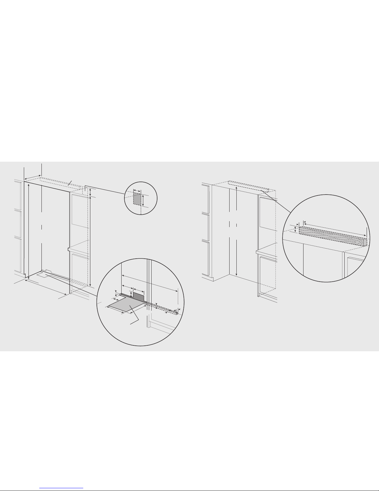
Cutout Dimensions (Side-By-Side)
42” Side-By-Side
42” Side-By-Side
One 2”x4” mounting board 1-1/2” (3.8 cm) x 3-1/2” (8.9 cm)
Note: If unit is installed deeper than 24” (61.0 cm), then shim behind
the mounting board by the difference.
Bottom of anti-tip board is 3-7/8” (9.8 cm) below the opening height.
Note: Top of unit must be placed firmly under anti-tip board.
19
18
One 2”x 4” mounting boards
1-1/2” (3.8 cm) x 3-1/2” (8.9 cm)
Note: If unit is installed deeper than 24” (61.0 cm), then shim
behind the mounting board by the difference.
Bottom of anti-tip board is 3-7/8” (9.8 cm) below opening height.
Note: Top of unit must be placed firmly under anti-tip board.
Anti-Tip Location
7
9-
3
/
8
”
(
2
0
1
.
6
c
m
)
m
i
n
.
t
o
b
o
t
t
o
m
o
f
a
n
t
i
-
t
i
p
b
o
a
r
d
8
0-
1
/
2
”
(
2
0
4
.
6
c
m
)
m
a
x.
t
o
b
o
t
t
o
m
o
f
a
n
t
i
-
t
i
p
b
o
a
r
d
4
1
”
(
1
0
4
.
1
c
m
)
3
-
1
/
2
”
(
8
.
9
c
m
)
1
-1
/
2
”
(
3
.
8
c
m
)
Anti-Tip Dimensions (Side-By-Side)
9
”
(
22
.
9 c
m
)
7
3
-
3
/
8
”
(18
6.
4
c
m
)
82
–
7
/
8
”
(
2
1
0
.
5
c
m
)
m
i
n
.
a
n
t
i
-
t
i
p
b
o
a
r
d
&
o
p
e
n
i
n
g
h
e
i
g
h
t
8
4
–
1
/
1
6
”
(
2
1
3
.
5
c
m
)
m
a
x
.
a
n
t
i
-
t
i
p
b
o
a
r
d
&
o
p
e
n
i
n
g
h
e
i
g
h
t
4
8
”
(
1
2
1
.
9
c
m
)
2
4
”
(
6
1
.
0
c
m
)
Electric Outlet Location
Water Line Entry Area
4
7
-
1
/
2
”
(
1
2
0
.
7
c
m
)
6
-
3
/
4
”
(
1
7
.
1
c
m
)
7
-
5
/
8
”
(
1
9
.
4
c
m
)
3
”
(
7
.
6
c
m
)
5
/
8
”
(
1
.
5
c
m
)
5
/
8
”
(
1
.
5
c
m
)
1
0
-
1
/
2
”
(
2
6
.
7
c
m
)
5
/
8
”
(
1
.
5
c
m
)
1
0
-
3
/
4
”
(
2
7
.
3
c
m
)
1
”
(
2
.
5
c
m
)
3
-
5
/
8
”
(
9
.
2
c
m
)
Optional floor
water line entry
S
e
e
a
n
t
i
-
t
i
p
b
o
a
r
d
i
n
s
t
a
l
l
a
t
i
o
n
6
”
(
1
5
.
2
c
m
)
9
”
(
2
2
.
9
c
m
)
Cutout Dimensions (Side-By-Side)
48” Side-By-Side
48” Side-By-Side
One 2”x4” mounting board 1-1/2” (3.8 cm) x 3-1/2” (8.9 cm)
Note: If unit is installed deeper than 24” (61.0 cm), then shim behind
the mounting board by the difference.
Bottom of anti-tip board is 3-7/8” (9.8 cm) below the opening height.
Note: Top of unit must be placed firmly under anti-tip board.
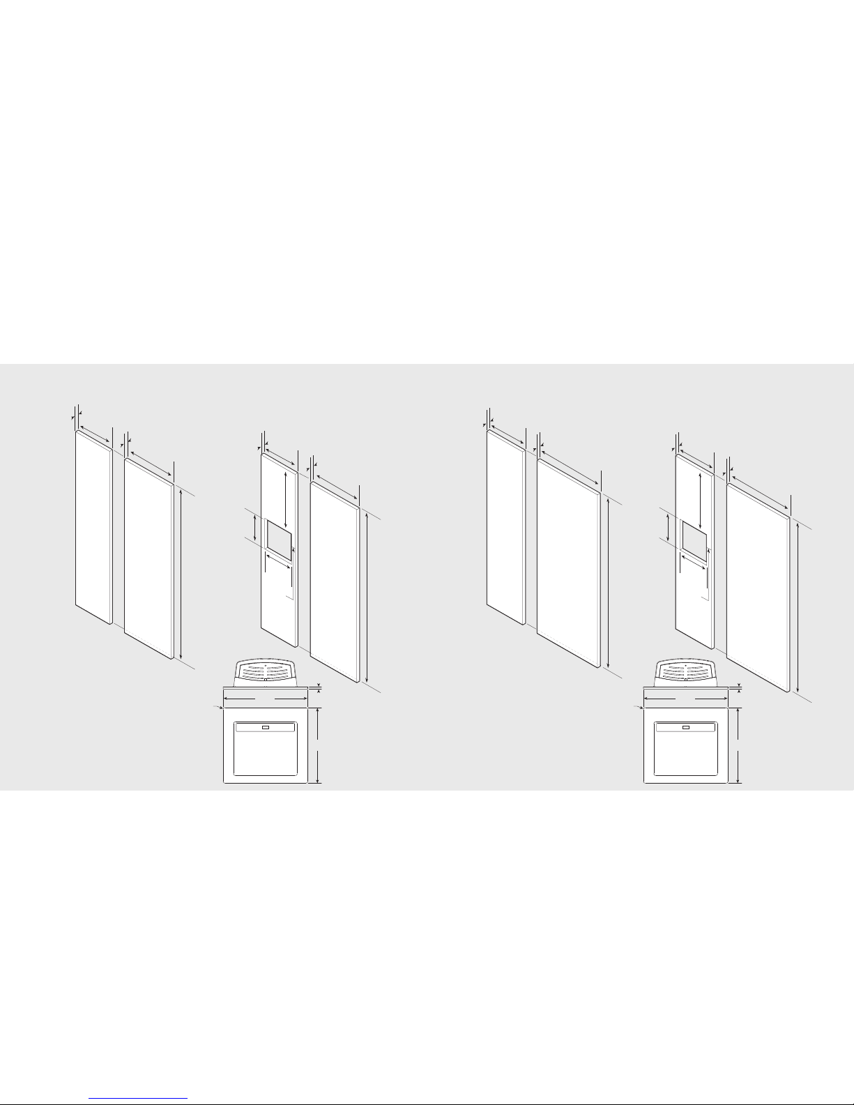
Overlay Dimensions (Side-By-Side)Overlay Dimensions (Side-By-Side)
21
20
Note: Panel overlays must be dry,
solid, straight one piece panels.
The use of multiple panel pieces to
achieve the dimensions is not
recommended.
2
2
-
1
3
/
1
6
”
(
5
7
.
9
c
m
)
75-
1/
2”
(
1
9
1
.
8
c
m
)
3/
4”
(
1.
9
c
m
)
3/
4”
(
1
.
9
c
m
)
1
8
-
3
/
1
6
”
(
4
6
.
2
c
m
)
2
2
-
1
3
/
1
6
”
(
5
7
.
9
c
m
)
75-
1/
2”
(
1
9
1
.
8
c
m
)
3/
4”
(
1.
9
c
m
)
1
8
-
3
/
1
6
”
(
4
6
.
2
c
m
)
31-
5/
8”
(
8
0
.
3
c
m
)
10-
11/
16”
(
2
7
.
1
c
m
)
12-
3/
8”
(
3
1
.
4
c
m
)
3/
4”
(
1.
9
c
m
)
3-
5/
32”
(
8
.
0
c
m
)
2
8
-
5
/
1
6
”
(
7
1
.
9
c
m
)
75-
1/
2”
(
1
9
1
.
8
c
m
)
3/
4”
(
1.
9
c
m
)
1
8
-
1
1
/
1
6
”
(
4
7
.
5
c
m
)
3/
4”
(
1.
9
c
m
)
2
8
-
5
/
1
6
”
(
7
1
.
9
c
m
)
75-
1/
2”
(
1
9
1
.
8
c
m
)
3/
4”
(
1.
9
c
m
)
1
8
-
1
1
/
1
6
”
(
4
7
.
5
c
m
)
31-
5/
8”
(
8
0
.
3
c
m
)
10-
11/
16”
(
2
7
.
1
c
m
)
12-
3/
8”
(
3
1
.
4
c
m
)
3/
4”
(
1.
9
c
m
)
3-
5/
32”
(
8
.
0
c
m
)
48” Custom Panels
with Dispenser
42” Custom Panels
with Dispenser
48” Custom Panels
42” Custom Panels
3/8”
(1.0 cm)
12-15/16”
(32.9 cm)
14-1/2”
(36.8 cm)
5/16”
(0.8 cm)
radius
Dispenser
Dimensions
Note: Panel overlays must be dry,
solid, straight one piece panels.
The use of multiple panel pieces to
achieve the dimensions is not
recommended.
3/8”
(1.0 cm)
12-15/16”
(32.9 cm)
14-1/2”
(36.8 cm)
5/16”
(0.8 cm)
radius
Dispenser
Dimensions
1
/
2
”
(
1
.
2
7
c
m
)
1
/
8
”
(
.
3
1
c
m
)
1
/
2
”
(
1
.
2
7
c
m
)
1
/
4
”
R
a
d
i
u
s
1/4” Radius
(
1
.
2
c
m
)
(1.2 cm)
1
/
4
”
R
a
d
i
u
s
(
.
6
4
c
m
)
Reverse dimensions
for other end.
7
/
8
”
(
2
.
2
2
c
m
)
1
/
2
”
(
1
.
2
7
c
m
)
2
-
1
/8
”
(
5
.
3
9
c
m
)
3
-
1
/8
”
(
7
.
9
4
c
m
)
3
-
5
/
8
”
(
9
.
2
0
c
m
)
1
-
3
/
8
”
(
3
.
4
9
c
m
)
3
/
8
”
(
.
9
5
c
m
)
3
/
8
”
R
a
d
i
u
s
3/8” Radius
(
.
9
5
c
m
)
(.95 cm)
3
/
8
”
R
a
d
i
u
s
(
.
9
5
c
m
)
4
7
-
1
/
2
”
(
1
2
0
.
6
5
c
m
)
1
/
2
”
(
1
.
2
7
c
m
)
3
-
1
/
8
”
(
7
.
9
3
c
m
)
O
p
t
i
o
n
a
l
h
i
n
g
e
c
o
v
e
r
4
6
”
(
1
1
6
.
8
4
c
m
)
1
/
2
”
(
1
.
2
7
c
m
)
3
-
5
/
8
”
(
9
.
2
0
c
m
)
4
5
-
1
5
/
1
6
”
(
1
1
6
.
6
8
c
m
)
4
6
”
(
1
1
6
.
8
4
c
m
)
3
/
4
”
(
1
.
9
0
c
m
)
3
/
4
”
(
1
.
9
0
c
m
)
3
-
3
/
4
”
(
9
.
5
2
c
m
)
3
-
3
/
4
”
(
9
.
5
2
c
m
)
3
”
(
7
.
6
2
c
m
)
3
”
(
7
.
6
2
c
m
)
3
/
4
”
(
1
.
9
0
c
m
)
3
0
-
2
7
/
3
2
”
(
7
8
.
3
4
c
m
)
3
2
-
3
/
1
6
”
(
8
1
.
7
5
c
m
)
1
1
-
1
7
/
3
2
”
(
2
9
.
2
8
c
m
)
1
0
-
1
1
/
6
4
”
(
1
5
.
8
4
c
m
)
1
/
2
”
(
1
.
2
7
c
m
)
1
-
1
/
2
”
(
3
.
8
1
c
m
)
1
/
4
”
R
a
d
i
u
s
(
.
6
4
c
m
)
2
-
3
/
4
”
(
6
.
9
8
c
m
)
1
/
2
”
(
1
.
2
7
c
m
)
3
/
4
”
(
1
.
9
0
c
m
)
Custom Grille Dimensions (Side-By-Side)
1
/
2
”
(
1
.
2
7
c
m
)
1
-
1
/
2
”
(
3
.
8
1
c
m
)
1
/
4
”
R
a
d
i
u
s
(
.
6
4
c
m
)
2
-
3
/
4
”
(
6
.
9
8
c
m
)
1
/
2
”
(
1
.
2
7
c
m
)
3
/
4
”
(
1
.
9
0
c
m
)
1
/
2
”
(
1
.
2
7
c
m
)
1
/
8
”
(
.
3
1
c
m
)
1
/
2
”
(
1
.
2
7
c
m
)
1
/
4
”
R
a
d
i
u
s
1/4” Radius
(
1
.
2
c
m
)
(1.2 cm)
1
/
4
”
R
a
d
i
u
s
(
.
6
4
c
m
)
Reverse dimensions
for other end.
7
/
8
”
(
2
.
2
2
c
m
)
1
/
2
”
(
1
.
2
7
c
m
)
2
-
1
/8
”
(
5
.
3
9
c
m
)
3
-
1
/8
”
(
7
.
9
4
c
m
)
3
-
5
/
8
”
(
9
.
2
0
c
m
)
1
-
3
/
8
”
(
3
.
4
9
c
m
)
3
/
8
”
(
.
9
5
c
m
)
3
/
8
”
R
a
d
i
u
s
3/8” Radius
(
.
9
5
c
m
)
(.95 cm)
3
/
8
”
R
a
d
i
u
s
(
.
9
5
c
m
)
4
1
-
1
/
2
”
(
1
0
5
.
4
1
c
m
)
1
/
2
”
(
1
.
2
7
c
m
)
3
-
1
/
8
”
(
7
.
9
3
c
m
)
O
p
ti
o
n
a
l
h
i
n
g
e
c
o
v
e
r
4
0
”
(
1
0
1
.
6
0
c
m
)
4
0
”
(
1
0
1
.
6
0
c
m
)
3
/
4
”
(
1
.
9
0
c
m
)
3
/
4
”
(
1
.
9
0
c
m
)
3
-
1
/
4
”
(
9
.
5
2
c
m
)
3
-
3
/
4
”
(
9
.
5
2
c
m
)
1
/
2
”
(
1
.
2
7
c
m
)
3
-
5
/
8
”
(
9
.
2
0
c
m
)
3
9
-
1
5
/
1
6
”
(
1
0
1
.
4
4
c
m
)
3
”
(
7
.
6
2
c
m
)
3
”
(
7
.
6
2
c
m
)
3
/
4
”
(
1
.
9
0
c
m
)
2
4
-
2
7
/
3
2
”
(
6
3
.
1
0
c
m
)
2
6
-
3
/
1
6
”
(
6
6
.
5
1
c
m
)
5
-
1
7
/
3
2
”
(
1
4
.
0
4
c
m
)
4
-
1
1
/
6
4
”
(
1
0
.
6
0
c
m
)
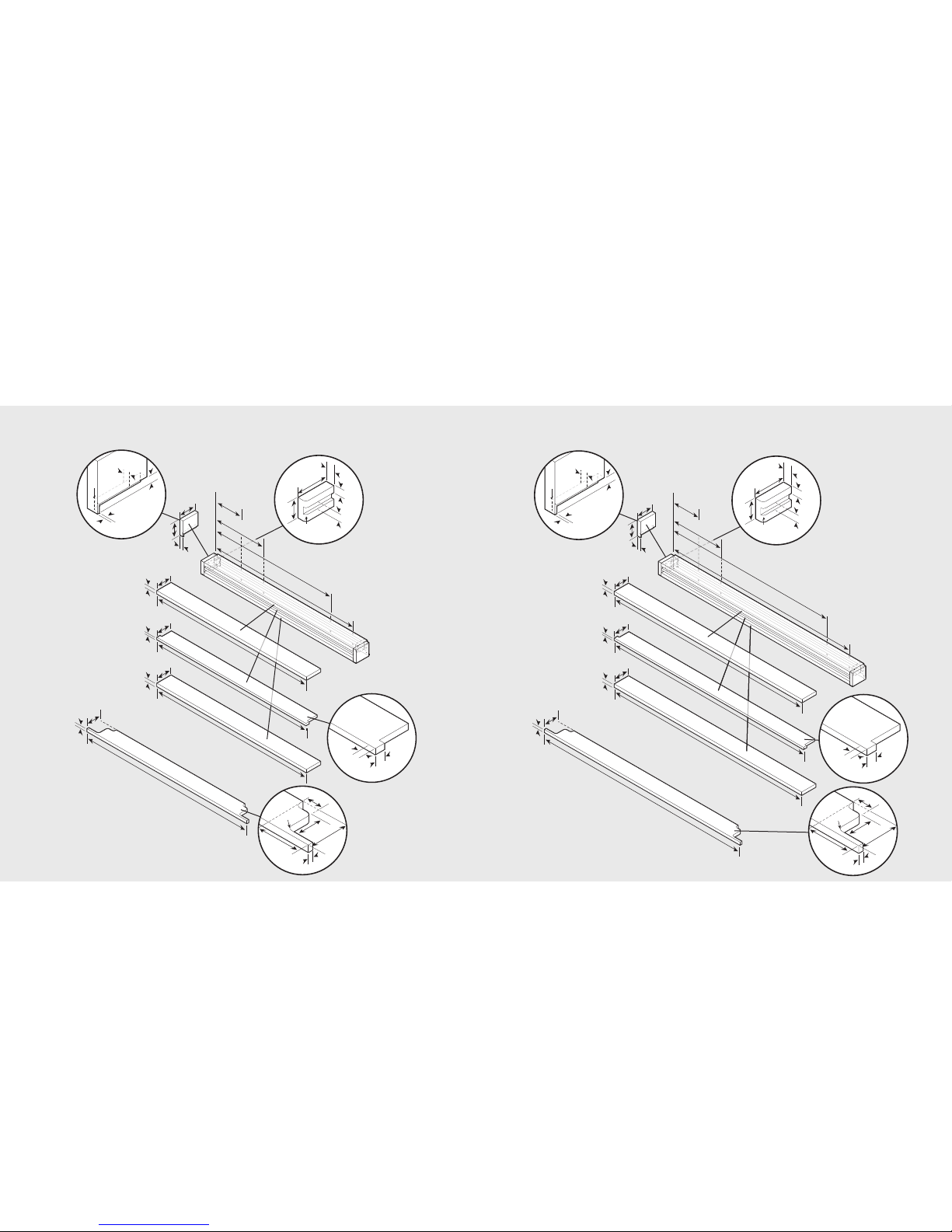
Custom Grille Dimensions (Side-By-Side)
23
22
42” Custom Grille 48” Custom Grille
Note: Optional hinge cover can be attached
using a strong VHB tape, countersunk wood
screws or short nails from a nail gun.
Note: Optional hinge cover can be attached
using a strong VHB tape, countersunk wood
screws or short nails from a nail gun.
 Loading...