

Viking DEVGIC305, DEVGIC365, DEVGIC485, DEVGRC365, DEVGRC485 Installation Manual
...
Viking Installation Guide
Freestanding Gas Ranges
IMPORTANT - PLEASE READ AND FOLLOW
•Before beginning, please read these instructions completely and carefully.
•Do not remove permanently affixed labels, warnings, or plates from the product. This may void the warranty.
•Please observe all local and national codes and ordinances.
•Please ensure that this product is properly grounded.
•The installer should leave these instructions with the consumer who should retain for local inspector’s use and for
future reference.
•The electrical plug should always be accessible.
Installation must conform with local codes or in the absence of codes, the National Fuel Gas Code ANSIZ223.1-latest
edition. Electrical installation must be in accordance with the National Electrical Code, ANIS/NFPA70 - latest edition
and/or local codes. IN CANADA: Installation must be in accordance with the current CAN/CGA-B149.1 National Gas
Installation Code or CAN/CGA-B149.2, Propane Installation Code and/or local codes. Electrical installation must be in
accordance with the current CSA C22.1 Canadian Electrical Codes Part 1 and/or local codes.
Installation of any gas-fired equipment should be made by a licensed plumber. A manual gas shut-off valve must be
installed in the gas supply line ahead of the oven in the gas stream for safety and ease of service.
IInn MMaassssaacchhuusseettttss::
type manual gas valve must be installed in the gas supply line to this appliance.
All gas products must be installed by a “Massachusetts” licensed plumber or gasfitter. A “T” handle
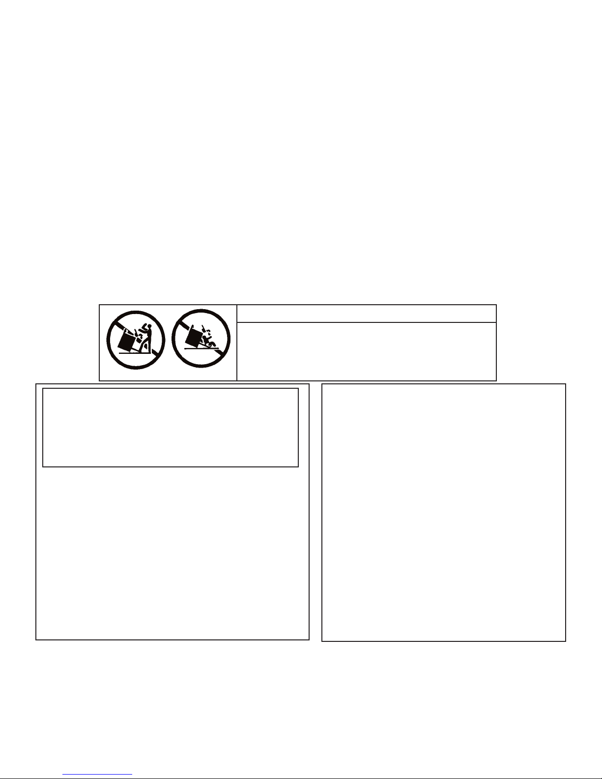
WWAARRNNIINNGG!!
•This range can tip.
•Injury to persons could result.
•Install anti-tip device packed with range.
•See Installation Instructions
WWAARRNNIINNGG::
MMAANNUUAALL IISS NNOOTT FFOOLLLLOOWWEEDD EEXXAACCTTLLYY,, AA
FFIIRREE OORR EEXXPPLLOOSSIIOONN MMAAYY RREESSUULLTT CCAAUUSSIINNGG
PPRROOPPEERRTTYY DDAAMMAAGGEE,, PPEERRSSOONNAALL IINNJJUURRYY,, OORR
DDEEAATTHH..
1. Do not store or use gasoline or other flammable vapors
and liquids in the vicinity of this or any other appliance.
WWHHAATT TTOO DDOO IIFF YYOOUU SSMMEELLLL GGAASS::
2.
•Do not try to light any appliance.
•Do not touch any electrical switch; do not use any
phone in your building.
•Immediately call your gas supplier from a neighbor’s
phone.
•Follow the gas supplier’s instructions.
•If you cannot reach your gas supplier, call the fire
department.
3. Installation and service must be performed by a qualified
installer, service agency, or the gas supplier.
IIFF TTHHEE IINNFFOORRMMAATTIIOONN IINN TTHHIISS
If not installed, operated and maintained in
accordance with the manufacturer’s instructions, this
product could expose you to substances in fuel or
from fuel combustion which can cause death or
serious illness and which are known to cause cancer,
birth defects, or other reproductive harm.
For example, benzene is a chemical which is part
of the gas supplied to the cooking product. It is
consumed in the flame during combustion.
However exposure to a small amount of benzene
is possible if a gas leak occurs. Formaldehyde
and soot are by-products of incomplete
combustion. Properly adjusted burners with a
bluish rather than yellow flame will minimize
incomplete combustion.
WWAARRNNIINNGG
1

GENERAL INFORMATION
WWAARRNNIINNGG::
1.
Combustible items may ignite, metallic items may become hot and cause burns. If a cabinet storage is to be
provided the risk can be reduced by installing a rangehood that projects horizontally a minimum of 5” (12.7 cm)
beyond the bottom of the cabinets.
WWAARRNNIINNGG::
2.
considerations.
3. All openings in the wall behind the appliance and in the floor under the appliance shall be sealed.
4. Keep appliance area clear and free from combustible materials, gasoline, and other flammable vapors.
5. Do not obstruct the flow of combustion and ventilation air.
6. Disconnect the electrical supply to the appliance before servicing.
7. When removing oven for cleaning and/or service;
A. Shut off gas at main supply
B. Disconnect AC power supply
C. Disconnect gas line to the inlet pipe.
D. Carefully remove the range by pulling outward.
8. Electrical Requirement
Listed on Specification sheet. Electrical installation should comply with national and local codes.
9. Gas Manifold Pressure
Natural gas 5.0” W.C.P.
LP/Propane 10.0” W.C.P.
10. Ventilation
It is recommended that the unit be set under a powered, vented exhaust hood of sufficient size and capacity. If
the unit incorporates a char-grill feature, the unit
hood of sufficient size and capacity.
11. Flexible Connections:
If this unit is to be installed with flexible couplings and/or quick disconnect fittings, the installer must use a flexible
connector approved by national and local codes.
12. The misuse of oven doors (e.g. stepping, sitting, or leaning on them) can result in potential hazards and/or injuries.
The use of cabinets for storage above the appliance may result in a potential burn hazard.
This appliance shall not be used for space heating. This information is based on safety
CCAAUUTTIIOONN::
mmuusstt
be used in conjunction with a powered, vented exhaust
Range is heavy; use care in handling.
When installing or removing the range for service, a rolling lift jack should be used. Do not push against any of the
edges of the range in an attempt to slide it into or out of the installation. Although all metal parts are deburred during
manufacturing, accidents could occur if the range should be moved suddenly or violently. Pushing or pulling a range
(rather than using a lift jack) also increases the possibility of bending the leg spindles or the internal coupling
connectors.
WARNING!!
ELECTRICAL GROUNDING INSTRUCTIONS
This range must be electrically grounded in accordance with local codes, or in the absence of local codes, with the
National Electrical Code, ANSI/NFPA70-latest edition. This appliance is equipped with 3-prong plug for your
protection against shock hazard and should be plugged directly into a properly grounded socket. Do not cut or
remove the grounding prong from this plug.
FFOORR PPEERRSSOONNAALL SSAAFFEETTYY,, TTHHIISS AAPPPPLLIIAANNCCEE MMUUSSTT BBEE PPRROOPPEERRLLYY GGRROOUUNNDDEEDD
LLeeggss
1. Legs are packed in styrofoam top pack.
2. Legs should be installed near to where the appliance is to be used, as they are not secure for long transit. After
unpacking the range, raise it about a foot to remove the bottom shipping skid. Keep the unit raised to permit the
legs to be screwed into our couplings and lower it gently to keep any undue strain from the legs and internal
mounting hardware. It is strongly recommended that a pallet or lift jack be used rather than tilting.
NNOOTTEE::
If legs are removed from range and range rests on a combustible surface, warranty will be void.
2
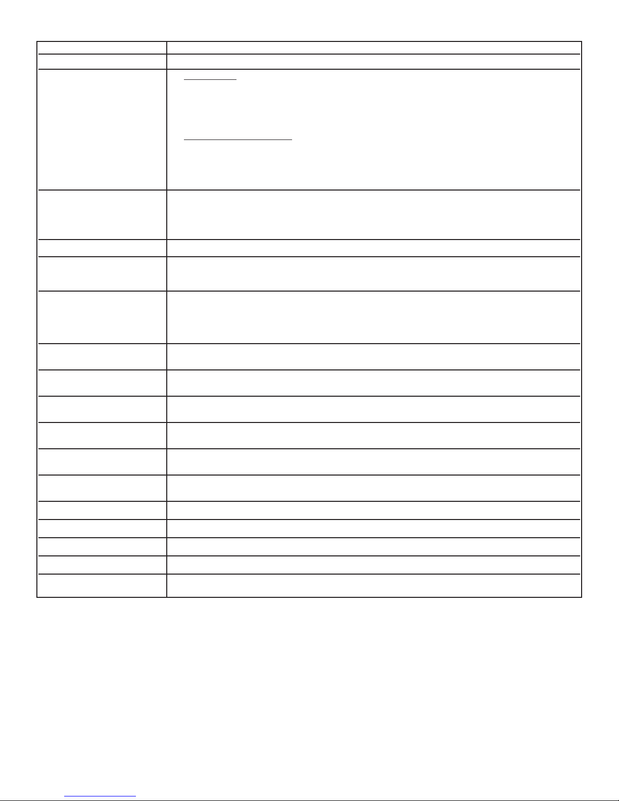
BASIC SPECIFICATIONS
DDeessccrriippttiioonn 2244”” WW.. MMooddeellss
Overall width 23 7/8” (60.6 cm)
Overall height Base Height
To top of grate support -
Min. 35 7/8 “ (91.1 cm) to
Max. 37 5/8” (95.6 cm)
Legs adjust 1 3/4” (4.5 cm)
Additions to Base Height
To top of grate - add 1 1/8” (2.9 cm)
To top of island trim - add 1 1/4” (3.2 cm)
To top of 6” backguard - add 6” (15.2 cm)
To top of high shelf - add 23 1/2” (59.7 cm)
Overall depth from rear
To end of side panel - 24 5/16” (61.8 cm)
To end of control panel - 26 1/4” (66.7 cm)
To end of knobs - 27 3/4” (70.5 cm)
Electrical requirements 120 VAC/60 Hz; 4 ft. (121.9 cm), 3-prong plug attached to the unit.
Gas requirements Shipped natural or LP/Propane gas; convert to Natural or LP/Propane conversion kit
(purchased separately); accepts standard residential 1/2” ID gas service line
Maximum amp usage 4B 4.3 amps
G 11.5 amps
Q 4.3 amps
K 4.3 amps
Surface burner rating 15,000 BTU Nat./13,500 BTU LP
(if applicable) (4.4 kW/4.0 kW)
Griddle burner rating Two 15,000 BTU ea. Nat./13,500 BTU ea. LP
(if applicable) (4.4 kW/4.0 kW)
Grill burner rating Two 18,000 BTU ea. Nat./16,000 BTU ea. LP
(if applicable) (5.3 kW/4.7 kW)
Wok burner rating 27,500 BTU Nat./LP
(8.1 kW)
Broil rating 15,000 BTU Nat./13,500 BTU LP
(4.4 kW/4.0 kW)
Bake rating 30,000 BTU Nat./LP
(8.8 kW)
Oven Interior width 18” (45.7 cm)
Oven Interior height 16 1/8” (41.0 cm)
Oven Interior depth 17 5/8” (44.8 cm)
Oven Interior overall size 3.0 cu. ft.
Approximate Shipping wt. 395 lbs. (177.8 kg)
Minimum clearances from the product to adjacent surfaces or construction:
• Below 36” (91.4 cm)
Sides - 0”
Rear - 0”
• Above 36” (91.4 cm)
Sides - 6” (15.2 cm)
Within the 6” (15.2 cm) side clearance, wall cabinets shall be no deeper than 13” (33.0 cm) and must be a minimum of 18” (45.7 cm) above
the countertop.
Rear - 0” with backguard or high shelf
0” with island trim and non-combustible heat resistant rear wall
6” (15.2 cm) with island trim and combustible rear wall
• Wall cabinets directly above the product must be minimum of 36” (91.4 cm) above the countertop for open top burners and 42” (106.7 cm) for
sealed burners.
To maintain product warranty, the responsibility for ensuring the use of non-combustible heat resistant materials when required, lies with individual
owner, contractor or end user.
*
Use range only with factory supplied legs.
3
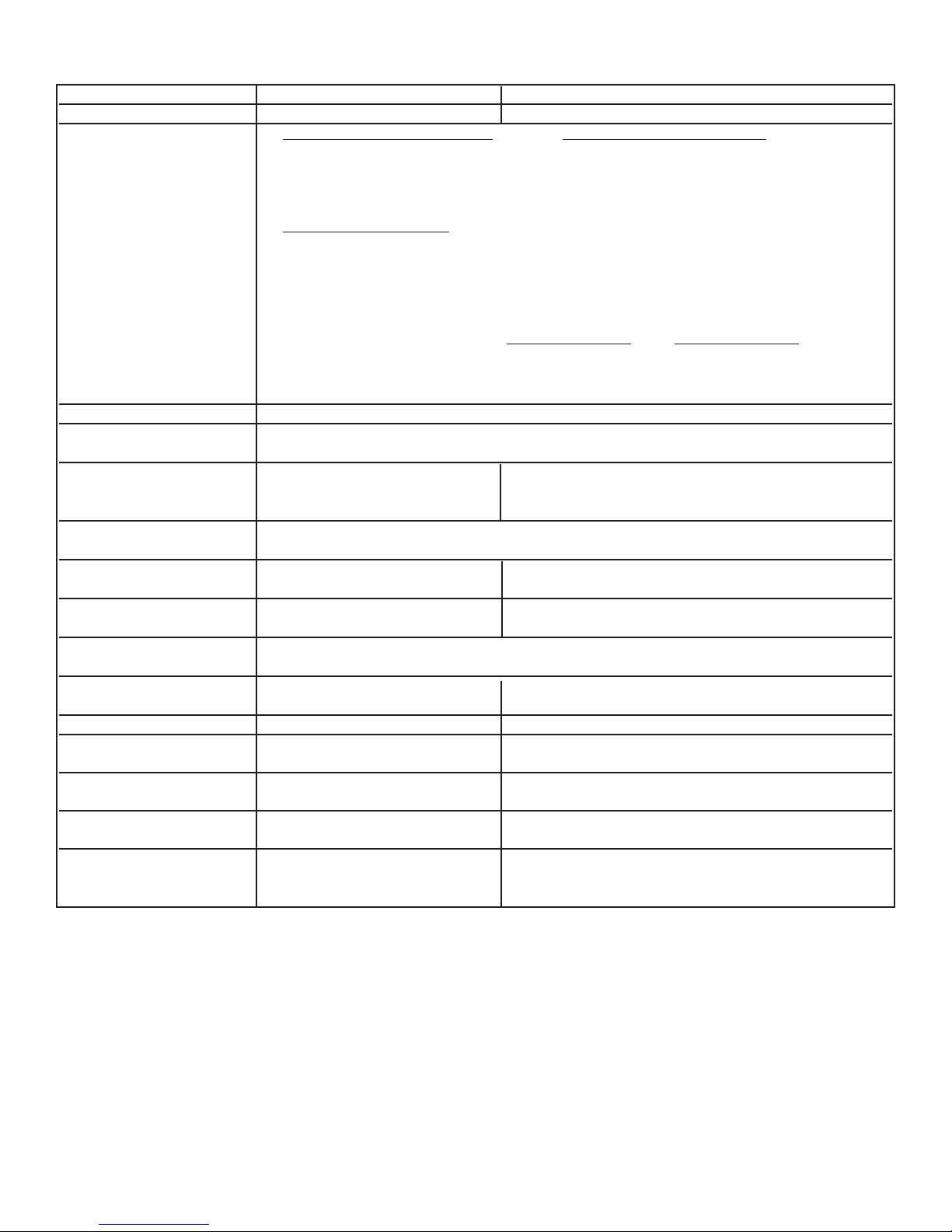
BASIC SPECIFICATIONS
DDeessccrriippttiioonn 3300”” WW.. MMooddeellss 3366”” WW.. MMooddeellss
Overall width 29 7/8” (75.9 cm) 35 7/8” (91.1 cm)
Overall height 24” Deep Models Base Height 27” Deep Models Base Height
To top of grate support -
Min. 35 7/8 “ (91.1 cm) to Min. 36 1/8” (91.8 cm
Max. 37 5/8” (95.6 cm) Max 39 1/8” (99.4 cm)
Legs adjust 1 3/4” (4.5 cm) Legs adjust 3” (7.6 cm)
Additions to Base Height
To top of spider grate - add 1 1/8” (2.9 cm)
To top of island trim - add 1 1/4” (3.2 cm)
To top of 6” backguard - add 6” (15.2 cm)
To top of 10” backguard - add 10” (25.4 cm)
To top of high shelf - add 23 1/2” (59.7 cm)
Overall depth from rear 24” Deep Models 27” Deep Models
To end of side panel - 24 5/16” (61.8 cm) 27” (68.6 cm)
To end of control panel - 26 1/4” (66.7 cm) 28 3/4” (73.0 cm)
To end of knobs - 27 3/4” (70.5 cm) 30 3/8” (77.2 cm)
Electrical requirements 120 VAC/60 Hz; 4 ft. (121.9 cm), 3-prong plug attached to the unit.
Gas requirements Shipped natural or LP/Propane gas; convert to Natural or LP/Propane conversion kit
(purchased separately); accepts standard residential 1/2” ID gas service line
Maximum amp usage/ 1.0 amps 6B - 8.5 amps
4G - 11.8 amps
4Q - 8.5 amps
Surface burner rating 15,000 BTU Nat./13,500 BTU LP
(4.4 kW/4.0 kW)
Griddle burner rating N/A 15,000 BTU Nat./12,500 BTU LP
(4.4 kW /3.7 kW )
Grill burner rating N/A 18,000 BTU Nat./16,000 BTU LP
5.3 kW (gross) / 4.7 kW (net)
Broil rating 18,000 BTU Nat./16,000 BTU LP
(5.3 kW/4.7 kW)
Bake rating 30,000 BTU Nat/LP Two 15,000 BTU ea. Nat./LP
(8.8 kW) (Two 4.4 kW ea.)
Oven Interior width 24” (61.0 cm) 30 1/8” (76.5 cm)
Oven Interior height 16 1/8” (41.0 cm) 24” D. Model- 16 1/8” (41.0 cm)
27” D. Model- 14 1/8” (35.9 cn)
Oven Interior depth 17 5/8” (44.8 cm) 24” D. Model- 17 5/8” (44.8 cm)
27” D. Model- 19 1/4” (48.9 cm)
Oven Interior overall size 4.0 cu. ft. 24” D. - 5.0 cu. ft.
27” D. - 4.7 cu. ft.
Approximate Shipping wt. 395 lbs. (173.3 kg) 6B - 447 lb. (201.2 kg)
4Q - 457 lb. (205.7 kg)
4G - 452 lb. (203.4 kg)
Minimum clearances from the product to adjacent surfaces or construction:
• Below 36” (91.4 cm)
Sides - 0”
Rear - 0”
• Above 36” (91.4 cm)
Sides - 6” (15.2 cm)
Within the 6” (15.2 cm) side clearance, wall cabinets shall be no deeper than 13” (33.0 cm) and must be a minimum of 18” (45.7 cm) above
the countertop.
Rear - 0” with backguard or high shelf
0” with island trim and non-combustible heat resistant rear wall
6” (15.2 cm) with island trim and combustible rear wall
• Wall cabinets directly above the product must be minimum of 36” (91.4 cm) above the countertop for open top burners and 42” (106.7 cm) for
sealed burners.
To maintain product warranty, the responsibility for ensuring the use of non-combustible heat resistant materials when required, lies with individual
owner, contractor or end user.
*
Use range only with factory supplied legs.
4
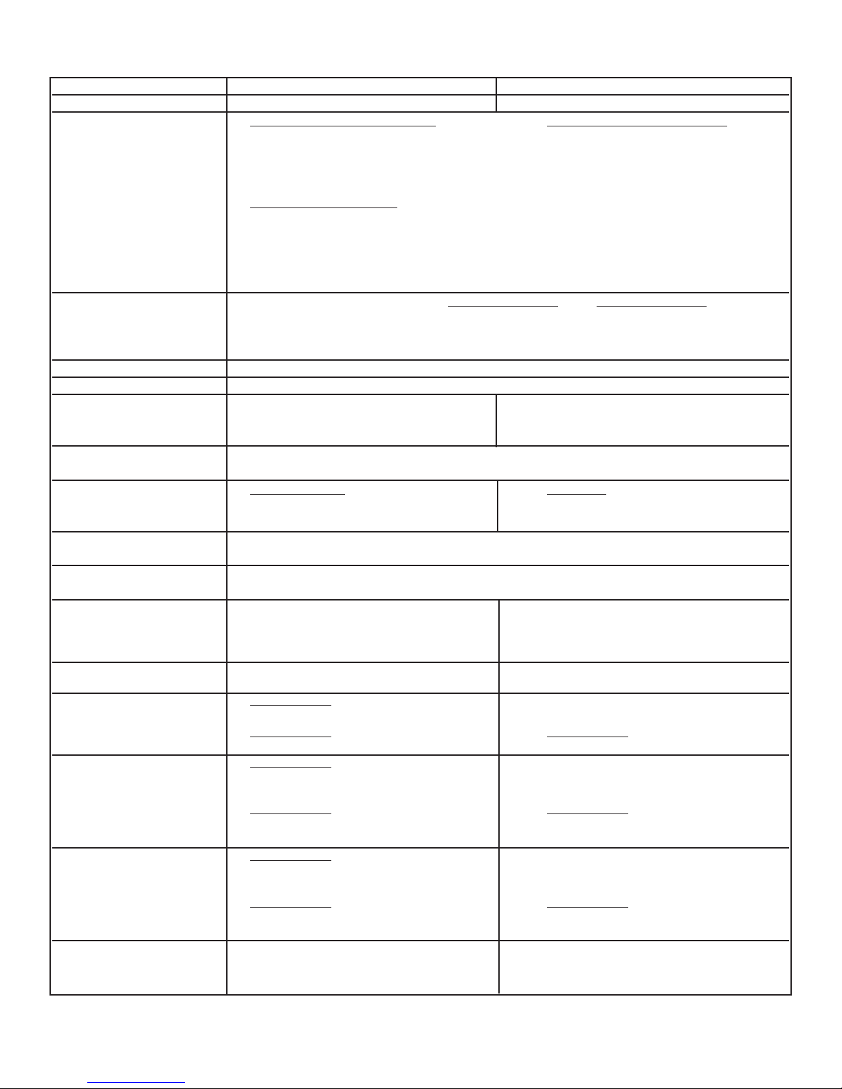
BASIC SPECIFICATIONS
DDeessccrriippttiioonn 4488”” WW.. MMooddeellss 6600”” WW.. MMooddeellss
Overall width 47 7/8” (121.6 cm) 59 1/2” (151.1 cm)
Overall height 24” Deep Models Base Height 27” Deep Models Base Height
To top of grate support -
Min. 35 7/8 “ (91.1 cm) to Min. 36 1/8” (91.8 cm
Max. 37 5/8” (95.6 cm) Max 39 1/8” (99.4 cm)
Legs adjust 1 3/4” (4.5 cm) Legs adjust 3” (7.6 cm)
Additions to Base Height
To top of spider grate - add 1 1/8” (2.9 cm)
To top of island trim - add 1 1/4” (3.2 cm)
To top of 6” backguard - add 6” (15.2 cm)
To top of 10” backguard - add 10” (25.4 cm)
To top of high shelf - add 23 1/2” (59.7 cm)
Overall depth from rear 24” Deep Models 27” Deep Models
To end of side panel - 24 5/16” (61.8 cm) 27” (68.6 cm)
To end of control panel - 26 1/4” (66.7 cm) 28 3/4” (73.0 cm)
To end of knobs - 27 3/4” (70.5 cm) 30 3/8” (77.2 cm)
Electrical requirements 120 VAC/60 Hz; 4 ft. (121.9 cm), 3-prong plug attached to unit
Gas requirements Shipped natural or LP/Propane gas; convert with conversion kit (purchased separately)
Maximum amp usage/ 6G - 16.0 amps 4Q - 12.4 amps 6G - 23.6 amps
6Q - 12.4 amps 4G - 19.6 amps 6GQ - 20.0 amps
4GQ - 16.0 amps
Surface burner rating 15,000 BTU Nat./13,500 BTU LP
(4.4 kW/4.0 kW)
Griddle burner rating 12” / 18” Wide 24” Wide
15,000 BTU Nat./12,500 BTU LP Two 15,000 BTU ea. Nat./12,500 BTU ea. LP
(4.4 kW/3.7 kW) (Two 4.4 kW ea./3.7 kW ea.)
Grill burner rating 12” - 1@ 18,000 BTU Nat. (5.3 kW)/16,000 BTU LP (4.7 kW)
24” - 2@ 13,000 BTU Nat./LP (4.4 kW)
Broil rating 18,000 BTU Nat./16,000 BTU LP
(5.3 kW/4.7 kW)
Bake rating Right - Two 15,000 BTU ea. Nat./LP Two 15,000 BTU ea. Nat./LP
(Two 4.4 kW ea.) (Two 4.4 kW ea.)
Left - One 15,000 BTU ea. Nat./LP Two 15,000 BTU ea. Nat./LP
(One 4.4 kW ea.) (Two 4.4 kW ea.)
Oven Interior width Right - 24 1/8” (61.3 cm) Both - 24 1/8” (61.3 cm)
Left - 13 3/8” (34.0 cm)
Oven Interior height 24” D. Models
Both - 16 1/8” (41.0 cm)
27” D. Models
Both - 14 1/8” (35.9 cm) Both- 14 1/8” (35.9 cm)
Oven Interior depth 24” D. Models
Right - 17 5/8” (44.8 cm)
Left - 18 3/4” (47.6 cm)
27” D. Models
Right - 19 1/4” (48.9 cm) Both - 19 1/4” (48.9 cm)
Left - 21 1/4” (54.0 cm)
Oven Interior overall size 24” D. Models
Right - 4.0 cu. ft.
Left - 2.3 cu. ft
27” D. Models
Right - 3.8 cu. ft. Both - 3.8 cu. ft.
Left - 2.3 cu. ft
Approximate Shipping wt. 6G - 591 lb. (266.0 kg) 4Q - 586 lb. (263.7 kg) 6G - 762 lb. (342.9 kg)
6Q - 586 lb. (263.7 kg) 4G - 596 lb. (268.5 kg) 6GQ - 757 lb. (340.7 kg)
4GQ - 596 lb. (268.5 kg)
(For Minimum Clearances from adjacent combustible construction refer to bottom of page 4.)
27” D. Models
27” D. Models
27” D. Models
5
 Loading...