

Page 1
PLANNING AND DESIGN GUIDE
VIKINGRANGE.COM • 1-888-VIKING1
RELEASED 02/05/10
©2010 VRC—INFORMATION SUBJECT TO CHANGE
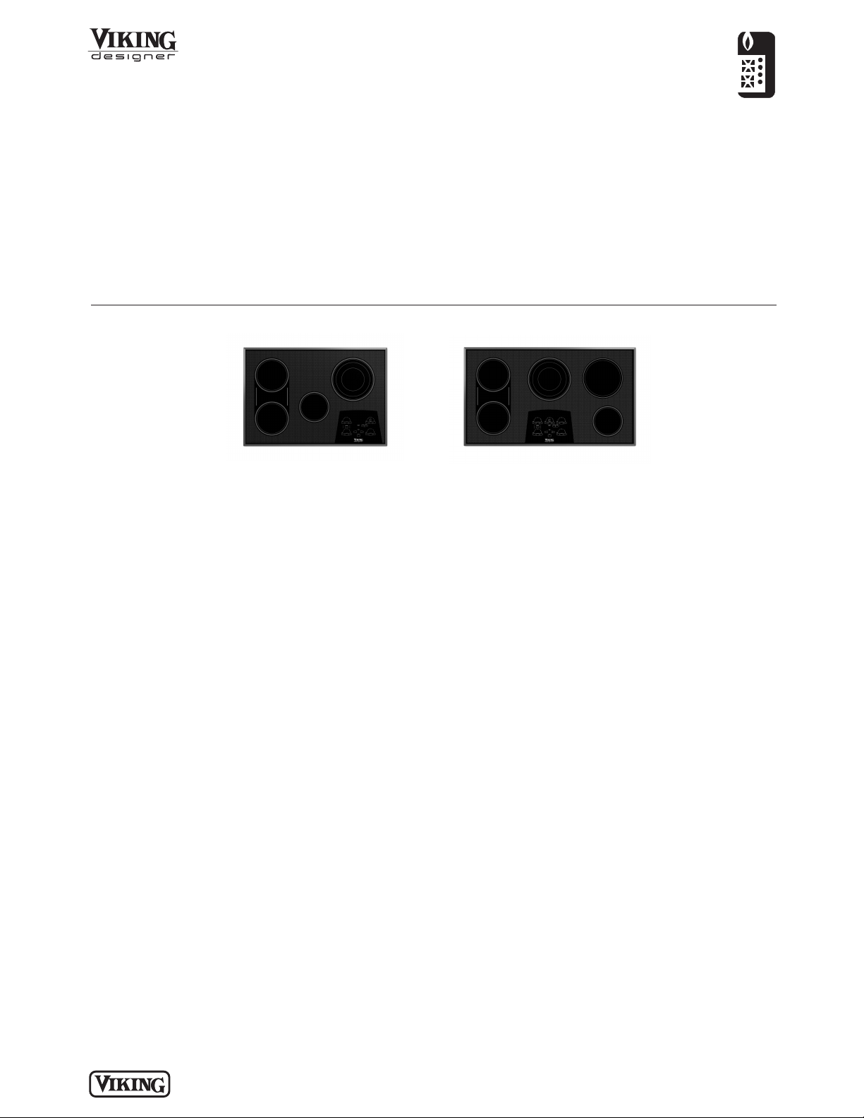
Both models include
• QuickCook™ surface elements utilize
ribbon element technology to reach
full power in about 3 seconds
• Bridge element between left front and
rear elements, creates a continuous
heated surface
• Dimensioned to fit the majority of
similarly sized cooktop cutouts
• Strong, wear-resistant glass ceramic
top offers excellent cleanability
4B model includes
• Four elements
o Left front— 7” 1,800 watts,
400 watts bridge
o Left rear—7” 1,800 watts
o Center—6” 1,500 watts
o Right rear—9”/7”/5” triple element
2,500/1,600/800 watts
5B model includes
• Five elements
o Left front— 7” 1,800 watts,
400 watts bridge
o Left rear—7” 1,800 watts
o Center—9”/7”/5” triple element
2,500/1,600/800 watts
o Right front—6” 1,500 watts
o Right rear—8” 2,100 watts
FINISH DETAILS FOR BOTH MODELS
• Black (BK)
o Black glass top
Standard Features & Accessories
Model Options
COOKING
Touch Control Electric 30”/36”W. Cooktop
DETU200-4B
30”W. Four-Element Cooktop
DETU260-5B
36”W. Five-Element Cooktop
ORDERING INSTRUCTIONS
First specify model number, and then color code (DETU200-4BBK).
Page 2
COOKING
Touch Control Electric 30”/36”W. Cooktop
PLANNING AND DESIGN GUIDE
VIKINGRANGE.COM • 1-888-VIKING1
RELEASED 02/05/10
©2010 VRC—INFORMATION SUBJECT TO CHANGE
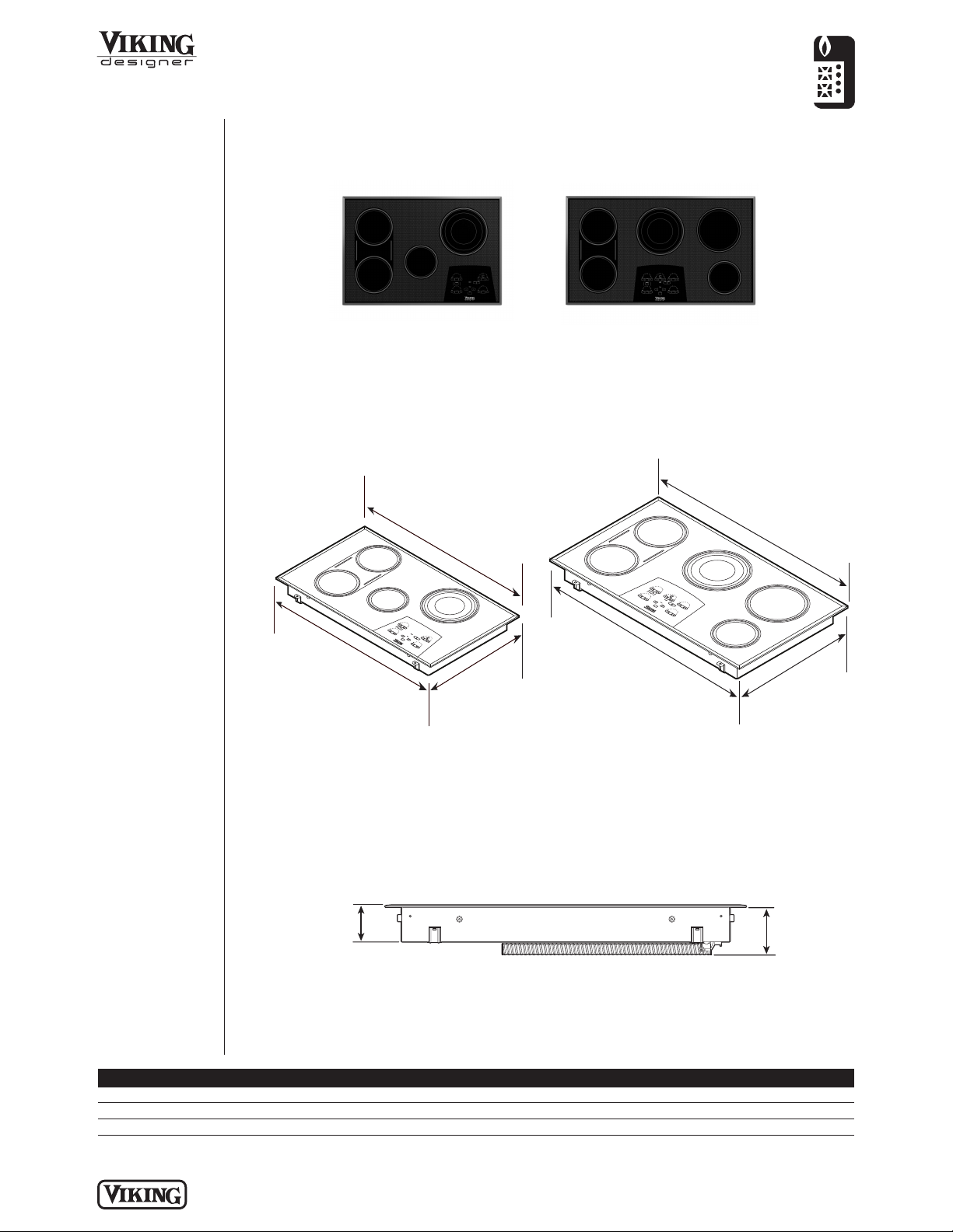
DETU200-4B DETU260-5B
Overall width 30-3/4” (78.1 cm) 36-3/4” (93.3 cm)
Overall height (top of cooktop to bottom) 3-1/8" (7.9 cm)
Overall depth (from rear) 21” (53.3 cm)
Dimensions & Specifications
OVERALL PRODUCT DIMENSIONS
DETU200-4B
30”W. Four-Element
Cooktop
DETU260-5B
36”W. Five-Element
Cooktop
30”W. Models 36”W. Models
3-1/8”
(7.9 cm)
4-1/4”
(10.8 cm)
FRONT VIEW
30-3/4 ”
(78.1cm)
30-3/4 ”
(78.1cm)
36-3/4 ”
(93.3 cm)
21”
(53.3 cm)
36-3/4 ”
(93.3 cm)
21”
(53.3)
Page 3

PLANNING AND DESIGN GUIDE
VIKINGRANGE.COM • 1-888-VIKING1
RELEASED 02/05/10
©2010 VRC—INFORMATION SUBJECT TO CHANGE
COOKING
Touch Control Electric 30”/36”W. Cooktop
Dimensions & Specifications
CLEARANCE DIMENSIONS
• Sides—minimum 8” (20.3 cm)
• Rear—minimum 1-1/2” (3.8 cm)
• From edge of cutout and front edge
of countertop 2-1/2” (6.35 cm)
• Within 8” (20.3) side clearance; wall
cabinets no deeper than 13” (33.0 cm)
• Countertop depth 25” (63.5 cm)
• Overhead cabinet depth from rear
maximum 13” (33.0 cm)
• Side cabinet height from countertop
minimum 18” (45.7 cm)
• Wall cabinets directly above cooktop
must be minimum 30” (76.2 cm) above
the countertop (unless ventilation
product is used).
1. The cooktop CANNOT be installed
directly adjacent to sidewalls, tall
cabinets or appliances, or other side
vertical surfaces above 30” (76.2 cm)
high. A minimum side clearance of 8”
(20.3 cm) is required between the
cooktop and such combustible
surfaces above the countertop.
2. A minimum height clearance of 18”
(45.7 cm) is required between the
countertop and wall cabinets no
deeper than 13” (33.0 cm) above the
countertop.
3. These dimensions are based on a
standard 24” (60.1 cm) deep base
cabinet with a 25” (63.5 cm) deep
countertop and 3/4” backsplash.
4. If a ventilation product is installed
over the cooktop, the minimum 30”
(76.2 cm) height clearance above the
unit does not apply. Refer to the
ventilation installation instructions for
further information.
Warning
The use of cabinets for storage above
the appliance may result in a potential
burn hazard. If a cabinet storage is to be
provided the risk can be reduced by
installing a hood that projects
horizontally a minimum of 5” (12.7 cm)
beyond the bottom of the cabinets.
Important: To ensure proper
performance and extend the life of the
electric components in the cooktop, it is
required that a minimum height
clearance of 1-1/2” (3.8 cm) be located
between the bottom of the induction
cooktop and any shelf or combustible
surface directly below the cooktop. This
includes the top edges of drawers
located directly beneath the cooktop. If a
shelf or drawer is located directly below
the cooktop, a 1” (0.4 cm) gap at the
front of the shelf or drawer is necessary
to allow for proper ventilation.
Minimum clearances from adjacent combustible construction
18” min.
(45.7 cm
13” max.
33.0 cm)
)
8” min.
(20.3 cm)
(
30” min.
(76.2 cm)
36” min.
91.4 cm)
(
2-1/2” min.
(6.35 cm)*
1-1/2” min.
(
3.8 cm)*
Page 4

DETU200-4B DETU260-5B
Cutout width (A) 28-3/4” (72.9 cm) min. to 29” (73.7 cm) max. 34” (86.4 cm) min. to 34-9/16” (87.8 cm) max.
Cutout height 3-1/8” (7.9 cm)
Cutout depth (B) 19-1/4” (49.0 cm) min. to 19-5/8” (49.8 cm) max.
Surface burner rating 240V
208V 240V 208V 240V 208V
Left front 1,800 watts 1,350 watts
Bridge 800 watts 600 watts
Left rear 1,800 watts 1,350 watts
Center 1,500 watts 1,125 watts 2,500/1,600/800 watts 2,500/1,600/800 watts
Right front N/A N/A 1,500 watts 1,125 watts
Right rear 2,500/1,600/800 watts 1,875/1,200/600 watts 2,100 watts 1,575 watts
COOKING
Touch Control Electric 30”/36”W. Cooktop
PLANNING AND DESIGN GUIDE
VIKINGRANGE.COM • 1-888-VIKING1
RELEASED 02/05/10
©2010 VRC—INFORMATION SUBJECT TO CHANGE
UTILITY
REQUIREMENTS
GAS
Not applicable
ELECTRICAL
• 3-wire, 240-208/
120VAC/60Hz; Unit
is equipped with
No. 10 ground wire
in conduit. Should be
fused separately.
• Maximum amp
usage—
o DETU200-4B
• 240V—35.0
• 208V—30.3
o DETU260-5B
• 240V—45.0
• 208V—40.0
PLUMBING
Not applicable
Installation Requirements
ACCESS REQUIREMENTS
DETU200-4B
30”W. Five-Element Cooktop
DETU260-5B
36”W. Five-Element Cooktop
30”W. Cutout* 36”W. Cutout*
Note: Based on a 24” deep cabinet with 3/4” backsplash.
27”
28-3/4”
(73.0 cm)
7/8”
(1.9 cm)
20-1/4”
(51.4 cm)
7/8”
(1.9 cm)
(68.6 cm)
2-1/4”
(5.7 cm)
7/8”
(1.9 cm)
33”
(83.8 cm)
34”
(86.4 cm)
7/8”
(1.9 cm)
20-1/4”
(51.4 cm)
2-1/4”
(5.7 cm)
B
A
Page 5

Compliance Information
WARRANTY INFORMATION*
• One-year full – complete unit
• Five-year limited – surface burner
• Ninety-day limited – cosmetic parts such as glass, painted items and decorative items
* For complete warranty see
Use & Care Guide
. Warranty valid on Viking products shipped within the United States and Canada.
COOKING
Touch Control Electric 30”/36”W. Cooktop
PLANNING AND DESIGN GUIDE
VIKINGRANGE.COM • 1-888-VIKING1
RELEASED 02/05/10
©2010 VRC—INFORMATION SUBJECT TO CHANGE
Page 6

 Loading...