

Viking Designer Series, VIV300, VIV600, VIV1200, VEV900 Installation Manual
...
Viking Installation Guide
Designer Series
Built-In 18” H. Hoods
Viking Range Corporation
111 Front Street
Greenwood, Mississippi 38930 USA
2
NNOOTTEE:: IIFF IINNSSTTAALLLLIINNGG HHOOOODD WWIITTHH
WWAARRMMIINNGG SSHHEELLFF PPAANNEELL,, IINNSSTTAALLLL
WWAARRMMIINNGG SSHHEELLFF PPAANNEELL FFIIRRSSTT..
IIMMPPOORRTTAANNTT --
PPLLEEAASSEE RREEAADD AANNDD FFOOLLLLOOWW
•Before beginning, please read these instructions
completely and carefully.
•Do not remove permanently affixed labels, warnings, or
plates from the product. This may void the warranty.
•Please observe all local and national codes and
ordinances. If no local codes are applicable, wire in
accordance with the National Electrical Code,
ANSI/NFPA 70-1990.
••CChheecckk wwiitthh aa qquuaalliiffiieedd aanndd ttrraaiinneedd iinnssttaalllleerr oorr llooccaall
ccooddeess ffoorr mmaakkeeuupp aaiirr rreeqquuiirreemmeenntt,, iiff aannyy..
•
TThhee iinnssttaalllleerr sshhoouulldd lleeaavvee tthheessee iinnssttrruuccttiioonnss wwiitthh tthhee
ccoonnssuummeerr wwhhoo sshhoouulldd rreettaaiinn ffoorr llooccaall iinnssppeeccttoorr’’ss uussee aanndd
ffoorr ffuuttuurree rreeffeerreennccee..
This hood is for residential installation only and is not
designed for installation over a commercial product.
Make sure power is off at the main circuit breaker or fuse
box before making connections.
TToo aavvooiidd rriisskk ooff ffiirree,,
eelleeccttrriicc sshhoocckk,, oorr iinnjjuurryy ttoo ppeerrssoonnss,, ttuurrnn ooffff tthhee eelleeccttrriicciittyy
ttoo tthhee hhoooodd ffrroomm tthhee ppoowweerr ssuuppppllyy bbeeffoorree sseerrvviicciinngg oorr
cclleeaanniinngg..
Viking Range hoods are equipped with variable speed
controls for blowers. These units will not function with a
single
speed ventilator. All Viking Range ventilator kits are
designed specifically for use with Viking Range hoods.
Use of
any non-Viking Range ventilator kit will void the hood
warranty.
WWAARRNNIINNGG
TTOO RREEDDUUCCEE TTHHEE RRIISSKK OOFF FFIIRREE,, EELLEECCTTRRIICCAALL SSHHOOCCKK,,
OORR IINNJJUURRYY TTOO PPEERRSSOONNSS,, OOBBSSEERRVVEE TTHHEE FFOOLLLLOOWWIINNGG::
1. Installation work and electrical wiring must be done by
qualified person(s) in accordance with all applicable
codes and standards, including fire-rated construction.
2. Sufficient air is needed for proper combustion and
exhausting of gases through the flue (chimney) of fuel
burning equipment to prevent back drafting. Follow
the heating equipment manufacturer’s guideline and
safety standards such as those published by the
National Fire Protection Association (NFPA), and the
American Society for Heating, Refrigeration and Air
Conditioning Engineers (ASHRAE), and the local code
authorities.
3. When cutting or drilling into wall or ceiling, do not
damage electrical wiring and other hidden utilities.
4. Ducted fans must always be vented to the outdoors.
5.
WWAARRNNIINNGG!!::
To reduce the risk of fire, use only metal
ductwork.
6.
CCAAUUTTIIOONN!!::
To reduce risk of fire and to properly
exhaust air, be sure to duct air outside. Do not vent
exhaust air into spaces within walls or ceilings, or into
attics, crawl spaces, or garages.
CCAAUUTTIIOONN
For general ventilating use only. Do not use
to exhaust hazardous or explosive materials
and vapors.
WWAARRNNIINNGG
TO REDUCE THE RISK OF FIRE, ELECTRICAL SHOCK,
OR INJURY TO PERSONS, RANGEHOODS MUST BE
INSTALLED WITH THE VENTILATORS THAT ARE
SPECIFIED ON THEIR CARTON INDICATING
SUITABILITY WITH THIS MODEL. OTHER VENTILATORS
CANNOT BE SUBSTITUTED.
WWAARRNNIINNGG
TTOO RREEDDUUCCEE TTHHEE RRIISSKK OOFF AA RRAANNGGEETTOOPP GGRREEAASSEE
FFIIRREE::
1. Never leave surface units unattended at high
setting. Boilovers cause smoking and greasy
spillovers that may ignite. Heat oils slowly on
low or medium settings.
2. Always turn hoon ON when cooking at high
heat or when cooking flaming foods.
3. Clean ventilating fans frequently. Grease should
not be allowed to accumulate on fan or filter.
4. Use proper pan size. Always use cookware
appropriate for the size of the surface element.
BBAASSIICC SSPPEECCIIFFIICCAATTIIOONNSS
IINNTTEERRIIOORR AANNDD EEXXTTEERRIIOORR PPOOWWEERR HHOOOODDSS
RREECCOOMM.. NNUUMMBBEERR OOFF 112200VVAACC//6600HHzz
DDEESSCCRRIIPPTTIIOONN CCFFMM
11
HHAALLOOGGEENN FFIILLTTEERRSS SSPPAACCEERRSS MMAAXX.. AAMMPPSS
33
((iinntt..--iinntteerriioorr;; eexxtt--eexxtteerriioorr
LLIIGGHHTTSS
((IInntteerriioorr//EExxtteerriioorr))
1188”” HH.. WWaallll
30”W.* 300 int/600 int./1200 int./900 ext./1200 ext. 2 2 0 2.4/4.6/6.6/6.6/3.9
36”W.*
300 int/600 int./1200 int./900 ext./1200 ext. 2 2 1 2.4/4.6/6.6/6.6/3.9
42”W.* 600 int./1200 int./900 ext./1200 ext. 2 3 0 4.6/6.6/6.6/4.0
48”W.
1200 int./1200 ext./1500 ext. 3 3 0 7.0/4.3/5.1
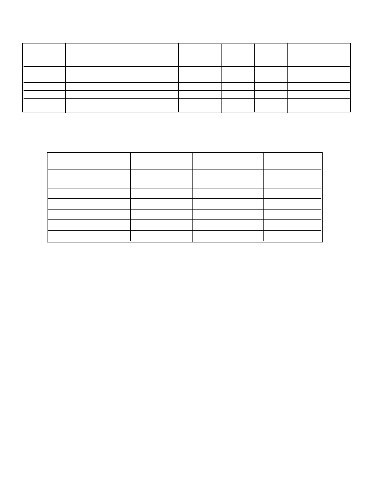
AAPPPPRROOXXIIMMAATTEE RREECCOOMMMMEENNDDEEDD MMAAXX.. DDUUCCTT
MMOODDEELL NNUUMMBBEERR CCFFMM
11
DDUUCCTT SSIIZZEE RRUUNN
22
((fftt..))
FFoorr UUssee wwiitthh hhooooddss::
VIV300 (interior) 300 7” round 50
VIV600 (interior) 600 7” round 50
VIV1200 (interior) 1200 10” round 50
VEV900 (exterior) 900 10” round 50
VEV1200 (exterior) 1200 10” round 50
VEV1500 (exterior) 1500 10” round 75
PPRROOPPEERR IINNSSTTAALLLLAATTIIOONN//DDUUCCTTIINNGG IISS EEXXTTRREEMMEELLYY IIMMPPOORRTTAANNTT TTOO EENNSSUURREE MMAAXXIIMMUUMM PPEERRFFOORRMMAANNCCEE FFRROOMM AANNYY
VVEENNTTIILLAATTIIOONN PPRROODDUUCCTT
1. •All CFMs stated are based on tests at .1 static pressure: without applying static pressure, CFM would be greatly
overstated.
2. •Duct run length is for general reference only; for longer duct runs, increase duct size and contact a qualified and trained
installer.
•Straight runs and gradual turns are best; for example, each 90
o
elbow is equivalent to 5-10 feet (1.52 - 3.05 cm) of
straight run.
•Never use flexible duct; it creates back pressure/air turbulence and greatly reduces performance.
•Proper performance is dependent upon proper ducting; make sure that a qualified and trained installer is used.
••CChheecckk wwiitthh aa qquuaalliiffiieedd aanndd ttrraaiinneedd iinnssttaalllleerr oorr llooccaall ccooddeess ffoorr mmaakkeeuupp aaiirr rreeqquuiirreemmeenntt,, iiff aannyy..
3. •Max. amp rating for hoods includes recommended ventilator kit rating; all products must be hard wired direct with 2wire with ground.
**11220000 CCFFMM ((oorr 11550000 CCFFMM iiff aapppplliiccaabbllee)) eexxtteerriioorr vveennttiillaattoorr sshhoouulldd bbee uusseedd wwhheenn iinnssttaalllleedd oovveerr
rraannggeess/
/rraannggeettooppss wwiitthh ggaass ggrriillll..
3
4
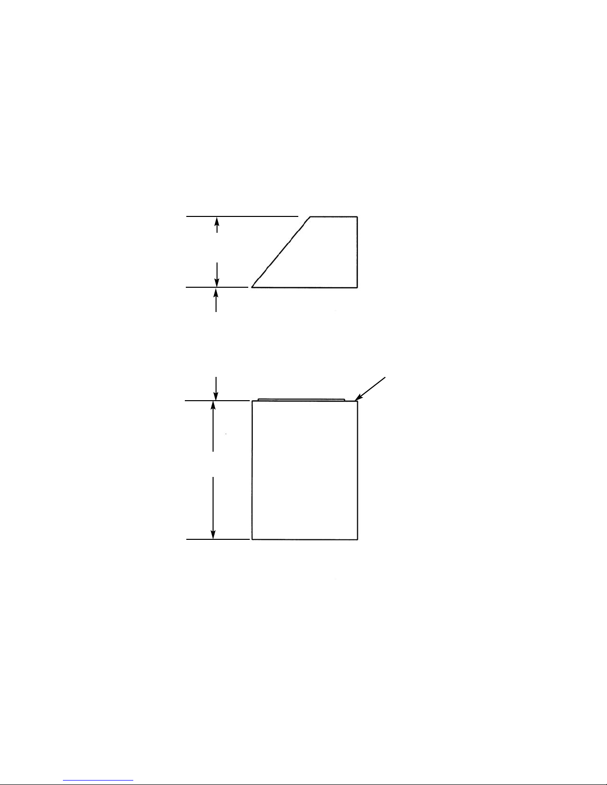
HHEEIIGGHHTT OOFF HHOOOODD
The bottom of the hood should be 30” (76.2 cm) min. to 36” (91.4 cm) max. above the countertop. This would
typically result in the bottom of the hood being 66” (167.6 cm) to 72” (182.9 cm) above the floor. For best
performance, it is recommended that the bottom of the hood be 30” (76.2 cm) to 33” (83.8 cm) above the
countertop. These dimensions provide for safe and efficient operation of the hood.
CClleeaarraannccee DDiimmeennssiioonnss
18”
(45.7 cm)
30”
(76.2 cm) Min.
36”
(91.4 cm) Max.
36”
(91.4 cm)
CCoouunntteerrttoopp
5
PPRREEPPAARRIINNGG FFOORR HHOOOODD IINNSSTTAALLLLAATTIIOONN
Plan where the ductwork will be located. See pages 8-11 for rough-in dimensions. Install proper-sized duct work, and
roof or wall cap for the type of blower you are using. Recommended hood locations for the most common
installations are shown on page 2.
Adjust your measurements for various heights of ceilings, soffits,
cabinets, or ranges/rangetops.
Roof Cap
7” Round
Duct
Roof Cap
10”
Round
duct
Duct Cover
or Soffit
Duct Cover
or Soffit
300 or 600 CFM
Interior-Power - Typical Ductwork
1200 CFM
Interior-Power - Typical Ductwork
Exterior Blower
10” Round
Duct
Duct
Cover
or Soffit
12”
(30.5 cm)
900, 1200, or 1500 CFM
Exterior-Power - Typical Ductwork
12”
(30.5 cm)
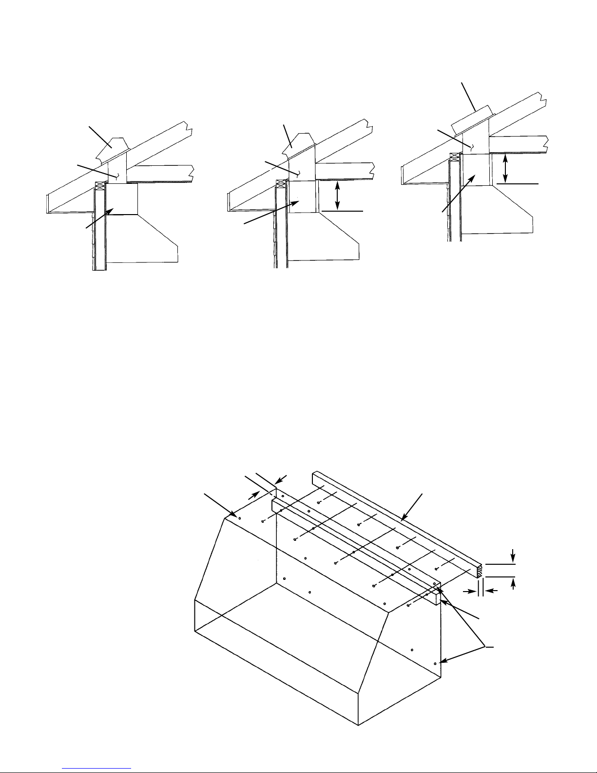
IINNSSTTAALLLLIINNGG HHOOOODD CCAANNOOPPYY
Center the wood strip (acquired locally - see drawing for dimensions) and attach to wall. Using the slot located on
the backside of the canopy, place the hood onto the wood strip. Secure the hood to strip with mounting screws
provided. Make sure that the wood strip mounting screws are driven into the framing and not just the drywall. Use
additional mounting screws (and wall anchors if necessary) in the other holes.
NNOOTTEE:: BBEECCAAUUSSEE OOFF
TTHHEE WWEEIIGGHHTT OOFF TTHHEE
HHOOOODD -- MMAAKKEE SSUURREE
TTHHAATT TTHHEE WWOOOODD SSTTRRIIPP
MMOOUUNNTTIINNGG SSCCRREEWWSS
AARREE DDRRIIVVEENN IINNTTOO TTHHEE
FFRRAAMMIINNGG AANNDD NNOOTT
JJUUSSTT TTHHEE DDRRYYWWAALLLL.. IITT
MMAAYY BBEE NNEECCEESSSSAARRYY TTOO
DDRRIILLLL AADDDDIITTIIOONNAALL
HHOOLLEESS IINN TTHHEE C
CAANNOOPPYY
FFOORR PPRROOPPEERR
AALLIIGGNNMMEENNTT..
EELLEECCTTRRIICCAALL SSUUPPPPLLYY
Run 120 VAC electrical power cable from service panel to installation location. See “Basic Specifications” on page 13
for the maximum amp requirements.
To p
Mounting
Holes
Wood Strip
(acquired locally- 1
1
/2” x
3
/4”)
Slot for Wood
Strip
Rear Mounting
Holes
11/
2”
(3.8 cm)
3
/4”(1.9 cm)
113/16”
(4.6 cm)
 Loading...