

Installation
Guide
7 SERIES
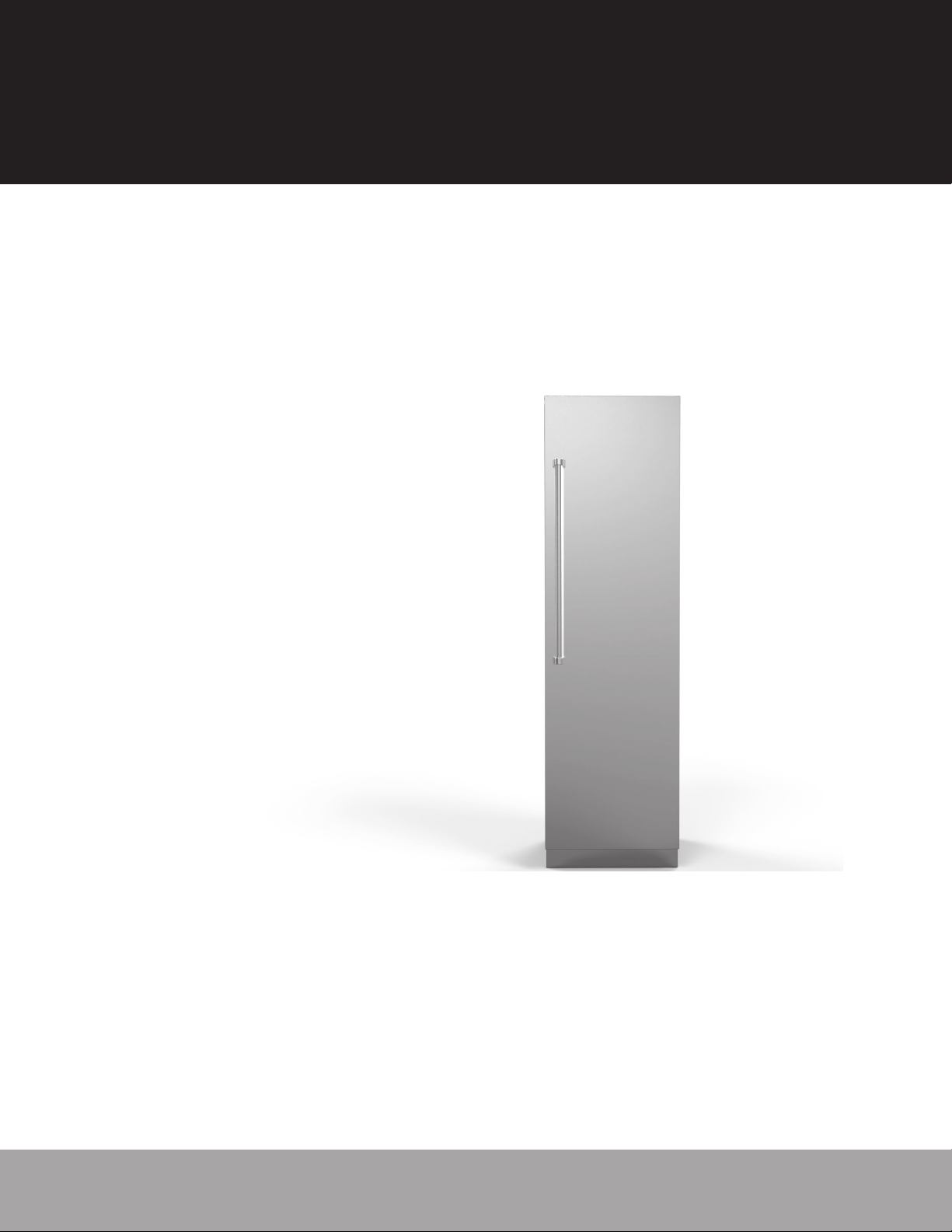
Integrated All Refrigerator
VRI7240 / CVRI7240 / VRI7300 / CVRI7300 / VRI7360 / CVRI7360
FRI7240 / CFRI7240 / FRI7300 / CFRI7300 / FRI7360 / CFRI7360
MVRI7240 / CMVRI7240 / MVRI7300 / CMVRI7300 / MVRI7360 / CMVRI7360
Integrated All Freezer
VFI7180 / CVFI7180/ VFI7240 / CVFI7240 / VFI7300 / CVFI7300 / VFI7360 / CVFI7360
FFI7180 / CFFI7180 / FFI7240 / CFFI7240 / FFI7300 / CFFI7300 / FFI7360 / CFFI7360
MVFI7180 / CMVFI7180 / MVFI7240 / CMVFI7240 / MVFI7300 / CMVFI7300 / MVFI7360 / CMVFI7360

Table of Contents
Warnings and Important Information ________________________________________________________________________________ 3
Cutout Dimensions___________________________________________________________________________________________ 5
Speci cations _______________________________________________________________________________________________ 6
Dimensions _______________________________________________________________________________________________ 10
Tipping Radius _____________________________________________________________________________________________ 11
Anti-Tip Dimensions ________________________________________________________________________________________ 12
General Information
Electrical Requirements ______________________________________________________________________________________ 13
Water Requirements _________________________________________________________________________________________ 14
Unpacking & Moving ________________________________________________________________________________________ 15
Installation
Custom Front Panel Dimensions _______________________________________________________________________________ 16
Custom Front Panel Install ____________________________________________________________________________________ 17
Water Line Installation _______________________________________________________________________________________ 18
Leveling Unit _______________________________________________________________________________________________ 19
Kickplate Installation _______________________________________________________________________________________ 20
Flush Mount Side Trim _______________________________________________________________________________________ 21
Door Panel Adjustments _____________________________________________________________________________________ 21
Door Stop Adjustment _______________________________________________________________________________________ 22
System Speci cations and Data ________________________________________________________________________________ 23
Performance Checklist ___________________________________________________________________________________________ 24
Control Panels __________________________________________________________________________________________________ 24
Service & Registration ___________________________________________________________________________________________ 25
2
IMPORTANT – Please Read and Follow!
• Make sure that incoming voltage is the same as unit rating. An electric
rating plate specifying voltage, frequency, wattage, amperage, and
phase is attached to the product.
• To reduce the risk of re, electrical shock, or injury to persons,
installation work and electrical wiring must be done by a quali ed
technician in accordance with all applicable codes and standards,
including re-rated construction.
• The installer should leave these instructions with the consumer who
should retain them for local inspector’s use and for future reference.
For additional information or installation videos, visit our website at
www.vikingrange.com
Your safety and the safety of others is very
important.
We have provided many important safety
messages in this manual and on your appliance.
ALWAYS read and obey all safety messages.
This is the safety alert symbol. This
symbol alerts you to hazards that
can kill or hurt you and others.
All safety messages will be preceded by the
safety alert symbol and the word “DANGER” or
“WARNING.” These words mean:
DANGER
You will be killed or seriously injured if you
don't follow instructions.
WARNING
You can be killed or seriously injured if you
don't follow instructions.
hazard, tell you how to reduce the chance
of injury, and tell you what can happen if
It is your responsibility to:
• comply with installation speci cations and dimensions.
• properly install unit.
• remove any moldings or decorative panels that prevent the unit from being serviced.
• make sure that you have these materials (not provided with your unit), which are necessary
for proper installation:
• 1/4” (6 mm) copper tubing with shuto valve
• 1– Saddle valve (do not use self-piercing feature of the valve)
• assure that oor will support unit, door panels and contents (approximately
1200 pounds [540 kg]).
• provide a properly grounded electrical outlet.
• assure that location will permit appliance doors to open 90º minimum.
Required tools
• Drill
• Drill bits - 3" Phillips (Ph2), Torx (T15 & T20), 1/4" and 5/16" hex drive
• Rubber mallet
• 3/8" wrench
All safety messages will identify the
the instructions are not followed.
3
IMPORTANT – Please Read and Follow!
A GFI shall be used if required by NFPA-70 (National Electric Code), federal/state/local laws, or local ordinances.
• The required use of a GFI is normally related to the location of a receptacle with respect to any signi cant sources of water or moisture.
• Viking Range, LLC will
requirements below.
If the use of a GFI is required, it should be:
• Of the receptacle type (breaker type or portable type
• Used with permanent wiring only (temporary or portable wiring
• On a dedicated circuit (no other receptacles, switches or loads in the circuit)
• Connected to a standard breaker of appropriate size (GFI breaker of the same size
• Rated for Class A (5 mA +/- 1 mA trip current) as per UL 943 standard)
• In good condition and free from any loose- tting gaskets (if applicable in outdoor situations)
• Protected from moisture (water, steam, high humidity) as much as reasonably possible
NOT warranty any problems resulting from GFI outlets which are not installed properly or do not meet the
NOT recommended)
NOT recommended)
NOT recommended)
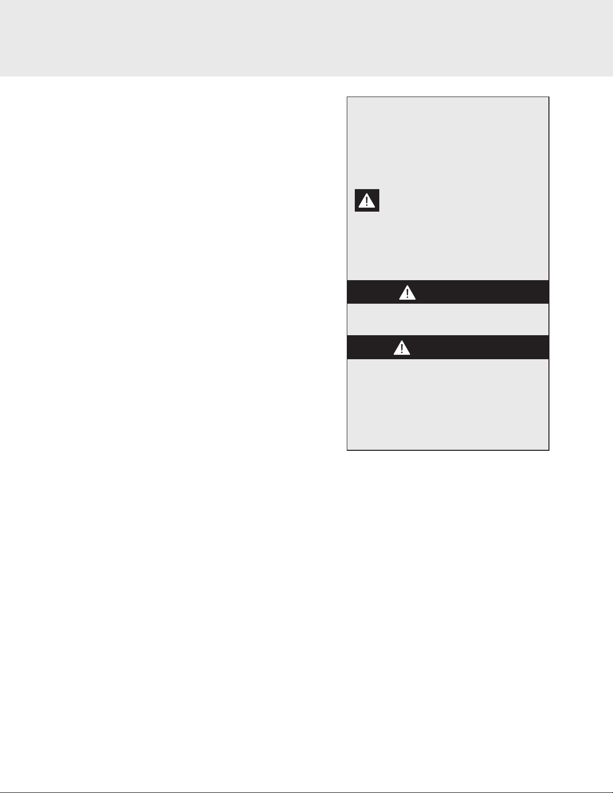
WARNING
ELECTRICAL SHOCK HAZARD
Disconnect power or turn
power disconnect switch to
OFF position before removing top grille.
Failure to do so can result in death or electrical shock.
Power On/O Switch
Your unit is shipped with the power switch on. When rst plugged in, the
display will ash. Push any button to initiate display.
The power on/o switch is located to the left of the center behind the
header panel. It is used to turn the power o when cleaning or servicing the
refrigerator.
To turn the power o , remove the header panel by using a small at head
screwdriver to pry between the breaker frame and the header panel on the
side closest to the hinge (see drawing A). There is a small pocket cut into the
bottom of the header panel at that location for that purpose. Once you have
pulled the header panel away from the unit (drawing B) enough to get your
ngers behind it slowly pull the opposite side away from the unit.
NOTE: There are wires connected to the backside of the header panel for the
Viking light and the WiFi board on the back of the light.
WARNING
TIP OVER HAZARD
Appliance is top heavy and tips easily
when not completely installed. Keep
doors closed until appliance is completely
installed and secured per installation
instructions.
Use two or more people to move and install appliance.
Failure to do so can result in death or serious injury.
power switch
A
B
To turn power on, press power on/o switch to the on position. Replace
header panel. IMPORTANT: Be sure the power on/o switch is in the on
position after cleaning or servicing.
4
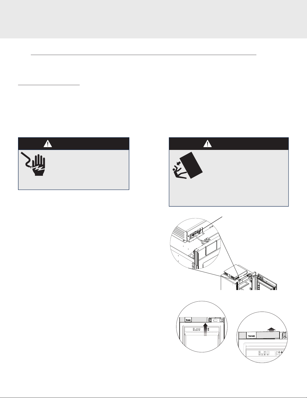
Cutout Dimensions
*
25”
(63.5 cm)
84”
(213.4 cm) min.
opening height
85-3/16”
(216.3cm) max.
op
ening height
Can be located on either side
Electric Outlet Location
15-1/2”
(39.4 cm)
4-1/4”
(10.8 cm)
+
leveling
dimension
Water Line Entry Area
*Refer to Specication
chart for
specic Models
*Note: For all models, 3” back from the front of the cabinet on
both sides needs to nished like the outside of the cabinets
5/8”
(1.6 cm)
1/2”
(1.3 cm)
*Cutout
Width
6”
(15.2 cm)
3”
(7.6 cm)
5
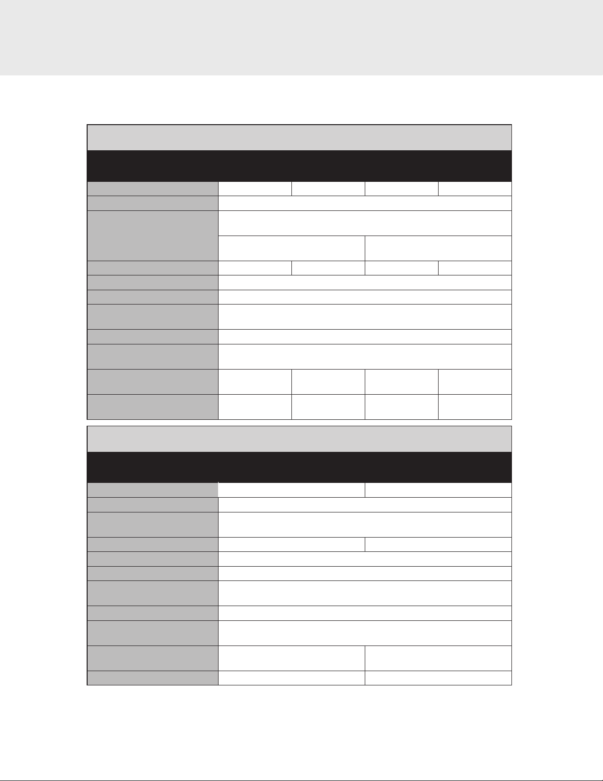
Speci cations (VRI/FRI/MVRI)
Integrated All Refrigerator
Description VRI MVRI
Overall width 24" (61.0 cm) 24" (61.0 cm)
Overall height (from bottom) 83-15/16" (213.2 cm) min to 84-3/4" (215.7 cm) max
Overall depth from rear To front edge kickplate: 22-1/16” (56.0 cm)
Cutout width 24" (61.0 cm) 24" (61.0 cm)
Cutout height 84" (213.4 cm) min to 85-3/16" (216.3 cm) max
Cutout depth 25” (63.5 cm) min.
Electrical requirements 115 volt, 60 Hz, 15 amp dedicated circuit; 3-wire cord with
Maximum amp usage 9.9 amps
Inlet water requirements 1/4” copper tubing inlet waterline; minimum 20 psi;
Overall interior capacity
Refrigerator
24" 24"
To front of door panel : 24-3/4” (62.9 cm)
To front of handle endcap:
27-11/16" (70.3 cm)
grounded 3-prong plug attached to product
maximum 120 psi
12.4 cu. ft.
(351.1 liters)
To front of handle endcap:
27-5/16" (69.4 cm)
12.4 cu. ft.
(351.1 liters)
Approximate shipping weight 450 lbs. (202.5 kg)
Integrated All Refrigerator w/Custom Panel
Description FRI - 24"
Overall width 24" (61.0 cm)
Overall height (from bottom) 83-15/16" (213.2 cm) min to 84-3/4" (215.7 cm) max
Overall depth from rear To front edge kickplate: 22-1/16” (56.0 cm)
To front of unit: 24” (61.0 cm)
Cutout width 24" (61.0 cm)
Cutout height 84" (213.4 cm) min to 85-3/16" (216.3 cm) max
Cutout depth 25” (63.5 cm) min.
Electrical requirements 115 volt, 60 Hz, 15 amp dedicated circuit; 3-wire cord with
grounded 3-prong plug attached to product
Maximum amp usage 9.9 amps
Inlet water requirements 1/4” copper tubing inlet waterline; minimum 20 psi;
maximum 120 psi
Overall interior capacity
Refrigerator 12.4 cu. ft. (351.1 liters)
Approximate shipping weight 450 lbs. (202.5 kg)
6
Speci cations ( VFI/FFI/MVFI)
Integrated All Freezer
Description VFI MVFI
Overall width 18" (45.7 cm) 24" (61.0 cm) 18" (45.7 cm) 24" (61.0 cm)
Overall height (from bottom) 83-15/16" (213.2 cm) min to 84-3/4" (215.7 cm) max
Overall depth from rear To front edge kickplate: 22-1/16” (56.0 cm)
Cutout width 18" (45.7 cm) 24" (61.0 cm) 18" (45.7 cm) 24" (61.0 cm)
Cutout height 84" (213.4 cm) min to 85-3/16" (216.3 cm) max
Cutout depth 25” (63.5 cm) min.
Electrical requirements 115 volt, 60 Hz, 15 amp dedicated circuit; 3-wire cord with
Maximum amp usage 9.9 amps
Inlet water requirements 1/4” copper tubing inlet waterline; minimum 20 psi;
Overall interior capacity
Freezer
Approximate shipping weight 350 lbs.
(232.2 liters)
18" 24" 18" 24"
To front of door panel : 24-3/4” (62.9 cm)
To front of handle endcap:
27-11/16" (70.3 cm)
grounded 3-prong plug attached to product
8.2 cu. ft.
(157.5 kg)
12.4 cu. ft.
(351.1 liters)
450 lbs.
(202.5 kg)
maximum 120 psi
To front of handle endcap:
27-5/16" (69.4 cm)
8.2 cu. ft.
(232.2 liters)
350 lbs.
(157.5 kg)
12.4 cu. ft.
(351.1 liters)
450 lbs.
(202.5 kg)
Integrated All Freezer W/Custom Panel
Description FFI
18" 24"
Overall width 18" (45.7 cm) 24" (61.0 cm)
Overall height (from bottom) 83-15/16" (213.2 cm) min to 84-3/4" (215.7 cm) max
Overall depth from rear To front edge kickplate: 22-1/16” (56.0 cm)
To front of unit: 24” (61.0 cm)
Cutout width 18" (45.7 cm) 24" (61.0 cm)
Cutout height 84" (213.4 cm) min to 85-3/16" (216.3 cm) max
Cutout depth 25” (63.5 cm) min.
Electrical requirements 115 volt, 60 Hz, 15 amp dedicated circuit; 3-wire cord with
grounded 3-prong plug attached to product
Maximum amp usage 9.9 amps
Inlet water requirements 1/4” copper tubing inlet waterline; minimum 20 psi;
maximum 120 psi
Overall interior dimensions
Freezer
Approximate shipping weight 350 lbs. (157.5 kg) 450 lbs. (202.5 kg)
8.4 cu. ft.
(238.9 liters)
12.2 cu. ft.
(361.2 liters)
7
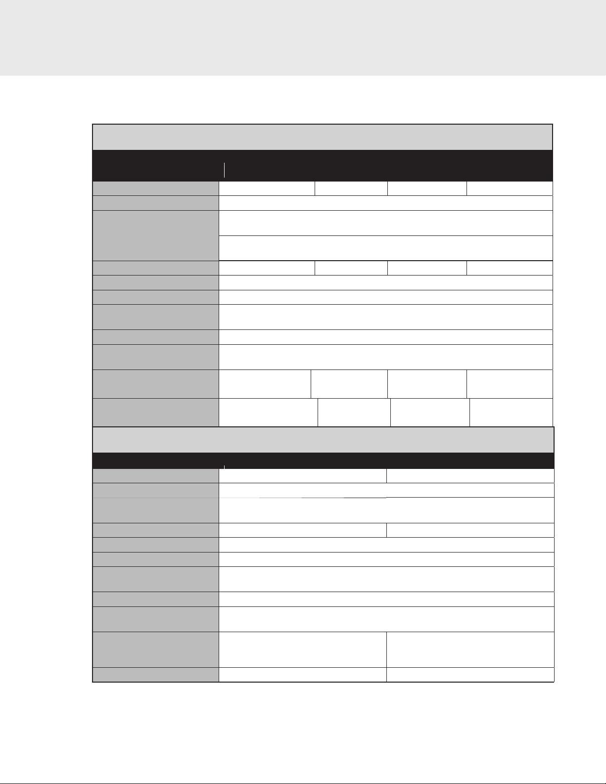
Speci cations (VRI/FRI/MVRI)
Integrated All Refrigerator
Description VRI MVRI
Overall width 30" (76.2 cm) 36" (91.4 cm) 30" (76.2 cm) 36" (91.4 cm)
Overall height (from bottom) 83-15/16" (213.2 cm) min to 84-3/4" (215.7 cm) max
Overall depth from rear To front edge kickplate: 22-1/16” (56.0 cm)
Cutout width 30" (76.2 cm) 36" (91.4 cm) 30" (76.2 cm) 36" (91.4 cm)
Cutout height 84" (213.4 cm) min to 85-3/16" (216.3 cm) max
Cutout depth 25” (63.5 cm) min.
Electrical requirements 115 volt, 60 Hz, 15 amp dedicated circuit; 3-wire cord with
Maximum amp usage 9.9 amps
Inlet water requirements 1/4” copper tubing inlet waterline; minimum 20 psi;
Overall interior capacity
Refrigerator
30" 36" 30" 36"
To front of door panel: 24-3/4” (62.9 cm)
To front of handle endcap:
27-5/16" (69.4 cm)
grounded 3-prong plug attached to product
maximum 120 psi
16.4 cu. ft
(464.4 liters)
20.5 cu. ft.
(580.5 liters)
16.4 cu. ft
(464.4 liters)
20.5 cu. ft.
(580.5 liters)
Approximate shipping weight 499 lbs.
(224.5kg)
502 lbs.
(225.9kg)
499 lbs.
(224.5kg)
(225.9kg)
Integrated All Refrigerator w/Custom Panel
Description FRI - 30" FRI - 36"
Overall width 30" (76.2 cm) 36" (91.4 cm)
Overall height (from bottom) 83-15/16" (213.2 cm) min to 84-3/4" (215.7 cm) max
Overall depth from rear To front edge kickplate: 22-1/16” (56.0 cm)
To front of unit: 24” (61.0 cm)
Cutout width 30" (76.2 cm) 36" (91.4 cm)
Cutout height 84" (213.4 cm) min to 85-3/16" (216.3 cm) max
Cutout depth 25” (63.5 cm) min.
Electrical requirements 115 volt, 60 Hz, 15 amp dedicated circuit; 3-wire cord with
grounded 3-prong plug attached to product
Maximum amp usage 9.9 amps
Inlet water requirements 1/4” copper tubing inlet waterline; minimum 20 psi;
maximum 120 psi
Overall interior capacity
Refrigerator
Approximate shipping weight 499 lbs. (224.5kg) 502 lbs. (225.9kg)
16.4 cu. ft
(464.4 liters)
20.5 cu. ft.
(580.5 liters)
502 lbs.
8

Speci cations (VRI/FRI/MVRI)
Integrated All Freezer
Description VFI MVFI
Overall width 30" (76.2 cm) 36" (91.4 cm) 30" (76.2 cm) 36" (91.4 cm)
Overall height (from bottom) 83-15/16" (213.2 cm) min to 84-3/4" (215.7 cm) max
Overall depth from rear To front edge kickplate: 22-1/16” (56.0 cm)
Cutout width 30" (76.2 cm) 36" (91.4 cm) 30" (76.2 cm) 36" (91.4 cm)
Cutout height 84" (213.4 cm) min to 85-3/16" (216.3 cm) max
Cutout depth 25” (63.5 cm) min.
Electrical requirements 115 volt, 60 Hz, 15 amp dedicated circuit; 3-wire cord with
Maximum amp usage 9.9 amps
Inlet water requirements 1/4” copper tubing inlet waterline; minimum 20 psi;
Overall interior capacity
Freezer
Approximate shipping weight 494 lbs.
(455.9 liters)
30" 36" 30" 36"
To front of door panel: 24-3/4” (62.9 cm)
To front of handle endcap:
27-11/16" (70.3 cm)
grounded 3-prong plug attached to product
16.1 cu. ft
(222.3kg)
20.1 cu. ft.
(569.2 liters)
497 lbs.
(223.7kg)
maximum 120 psi
To front of handle endcap:
27-5/16" (69.4 cm)
16.1 cu. ft
(455.9 liters)
494 lbs.
(222.3kg)
20.1 cu. ft.
(569.2 liters)
497 lbs.
(223.7kg)
Integrated All Freezer W/Custom Panel
Description FFI
30" 36"
Overall width 30" (76.2 cm) 36" (91.4 cm)
Overall height (from bottom) 83-15/16" (213.2 cm) min to 84-3/4" (215.7 cm) max
Overall depth from rear To front edge kickplate: 22-1/16” (56.0 cm)
To front of unit: 24” (61.0 cm)
Cutout width 30" (76.2 cm) 36" (91.4 cm)
Cutout height 84" (213.4 cm) min to 85-3/16" (216.3 cm) max
Cutout depth 25” (63.5 cm) min.
Electrical requirements 115 volt, 60 Hz, 15 amp dedicated circuit; 3-wire cord with
grounded 3-prong plug attached to product
Maximum amp usage 9.9 amps
Inlet water requirements 1/4” copper tubing inlet waterline; minimum 20 psi;
maximum 120 psi
Overall interior dimensions
Freezer
Approximate shipping weight 494 lbs. (222.3kg) 497 lbs. (223.7kg)
16.1 cu. ft
(455.9 liters)
20.1 cu. ft.
(569.2 liters)
9

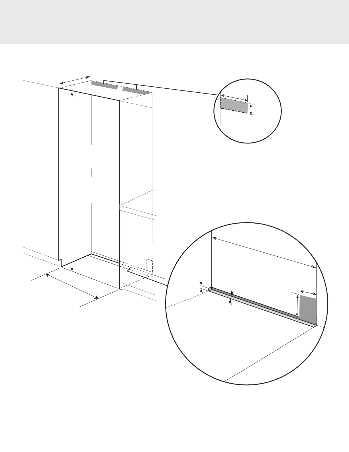
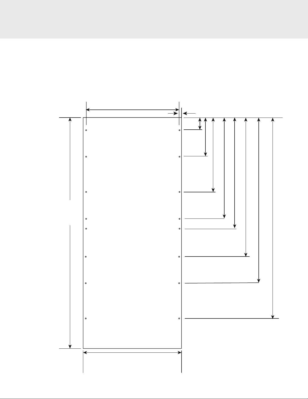
Dimensions
83-15/16”
(213.2 cm)
22-1/16”
(56.0 cm)
B
A
Model Dimension A Dimension B*
VRIVFI
FRI/FFI
MVRI/MVFI
4-1/16”
(10.3 cm)
27-11/16" (70.3 cm) 24-3/4" (62.9 cm)
N/A 24" (61.0 cm)
27-5/16" (69.4 cm) 24-3/4" (62.9 cm)
*To outside of door panel
10

Door Swing / Tipping Radius
18" 24" 30" 36"
A 19-1/16" (48.4 cm) 25-3/16" (64.0 cm) 31-3/8" (79.7 cm) 37-1/4" (94.6 cm)
B 20-1/16" (51.0 cm) 26-1/16" (66.2 cm) 32-1/16" (96.5 cm) 39-5/16" (99.9 cm)
C 4-1/2" (11.4 cm) 6-3/16" (15.7 cm) 7-7/8" (20.0 cm) 9-1/2" (24.1 cm)
C
105090
113" (287.0 cm)
A
127-3/16" (323.1 cm)
B
0
D
83-15/16"
(213.2 cm)
24-3/4" (62.9 cm)
18" 24" 30" 36"
87-3/4"
(222.9 cm) 83-15/16"
(213.2 cm)
11
D 86"
(218.4 cm)
88"
(223.5 cm)
90"
(228.6 cm)
92"
(233.7 cm)

Anti-Tip Dimensions
WARNING
TIP OVER HAZARD
Appliance is top heavy and tips easily when not
completely installed. To avoid a hazard due to instability
of the appliance, it must be installed according to the
instructions including the anti-tip bracket
C
Cabinet
Opening
C
Anti-tip Bracket
The anti-tip bracket has holes set up on a grid in order to better locate a
wall stud. At least 4 places must be used.
NOTE: Number and type of fasteners must be suitable in order to
prevent tipping. For example: use wood screws into wall studs or
masonry anchors if attaching to stone, brick or concrete.
If a wall stud can not be found, use
the lower section of the bracket
and mount to the base board
Cabinet
Floor
Dimension A = Cabinet opening minus the refrigerator height + 1-1/4" (3.2 cm)
12
A
Rear

General Information
Area Requirements
Verify the following:
• Unit can t into residence and can be moved around corners and
through doorways.
• Floors can support unit’s weight plus food weight (approximately
1200 pounds [540 kg] per unit).
• Floors underneath refrigerator are level with surrounding nished
oor.
• Remove anything attached to rear or side walls that can obstruct
unit installation.
• Cutout dimensions are accurate.
• Electrical outlet is in correct location.
• Water line is in correct location.
•
DO NOT install a refrigeration unit near a heat source, nor in a
location where the surrounding temperature will fall below
60º F (16º C).
• Keep ventilation openings clear of obstructions.
Electrical Requirements
It is the customer’s responsibility to:
• Contact a quali ed electrical installer.
• Assure that the electrical installation is adequate and in
conformance with the National Electrical Code, ANSI/NFPA
70-latest edition or Canadian Electrical Code C22.1-1998 and
C22.2 No. 0-M91 (or latest edition), and all local codes and
ordinances.
A 115 volt, 60-Hz, 15 amp, fused, electrical supply is required. It
is required that a separate circuit serving only this appliance be
provided. In a dual installation, each appliance must have a separate
115 volt, 60-Hz, 15 amp, fused, electrical supply. This appliance is
equipped with a power supply cord having a 3-prong grounding
plug. To minimize possible shock hazard, the cord must be plugged
into a mating 3-prong, grounding-type wall receptacle.
If the supply cord is damaged, it must be replaced by the
manufacturer or it service agent or a quali ed service technician in
order to avoid a hazard.
DO NOT use an extension cord or ungrounded (two-prong)
adapter.
If codes permit a separate grounding wire
to be used, it is recommended that a quali ed electrician determine
that the grounding path is adequate.
Anti-Tip Requirements
The anti-tip device should be installed prior to moving the unit into
place.
Water Supply Requirements
WARNING
To avoid serious illness or death, connect to a potable
water supply only. DO NOT use unit where water
is microbiologically unsafe or of unknown quality,
without adequate disinfection before or after the
system. Systems certi ed for cyst reduction may be
used on disinfected water that may contain lterable
cysts. The contaminants or other substances removed
or reduced by this water treatment system are not
necessarily in your water.
CAUTION
Be sure to have a replacement cartridge available when
lter change is required.
• If water ltration system has been allowed to freeze,
replace lter cartridge.
• If system has not been used in several months, and
water has an unpleasant taste or odor, ush system by
dispensing 2-3 glasses of water. If unpleasant taste or
odor persists, change lter cartridge.
• Make sure to tighten the water lter to its home position.
An improper tightened water lter will not allow the
water to ow.
Use only 1/4” (6 mm) copper tubing for water line. DO
NOT install copper tubing in area where temperatures
drop below 35º F (1.7º C). Before attaching copper tubing
to the unit, ush at least 2 quarts (1.9 L) of water through
the copper tubing and into a bucket to remove any
particles in the water line.
• Viking Range, LLC is not responsible for property
damage due to improper installation or water
connection.
DO NOT ground to a gas line. Check with a quali ed electrician if
you are not sure if theappliance is properly grounded.
have a fuse in the neutral or grounding circuit.
DO NOT
13

General Information
Water Supply Requirements (con't)
• Connect 1/4” (6 mm) exible copper tubing to household
plumbing in compliance with local codes and ordinances.
• Length of copper tubing must reach from water supply
connection to the unit connection with an additional length
to facilitate moving the unit out of enclosure for cleaning or
service. Tubing should be soft instead of rigid and ends should
be free of burrs.
• Copper tubing route must be above 35º F
(1.7º C) to prevent water line from freezing.
• DO NOT use plastic water lines from the household
plumbing to the water inlet valve connection on the
refrigeration unit.
• DO NOT use the self-piercing feature of a saddle
valve. The hole made by the piercing lance is too small for the
water ow rate required by the ice maker.
• If saddle valve is not used, place a separate shut-o valve in an
easily accessible location between water supply and the unit.
DO NOT install shut-o valve behind the unit.
• The installation of Viking Range, LLC units with a reverse
osmosis system is acceptable
pressure remains within the allowable PSI as stated
below. It is important to note that with many reverse osmosis
systems, the pressure starts o high, but then it decreases as
the water level of the reverse osmosis storage area drops. This
must be considered when checking the water pressure coming
into the unit.
• Connect to a vertical or horizontal 1/2” (1.3 cm) to 1-1/4” (3.2
cm) COLD water line near water area.
• Run water line through the oor, back, or side wall in area
shown on page 7. Connect to water supply coming from back
of unit on the left side.
• Water pressure must be greater than 20 psi and less than 120
psi on non-dispenser units and greater than 35 psi and less
than 120 psi on dispenser units.
as long as the water
Area Requirements
• Most of the unit’s weight is at the top. Extra care is needed when
moving the unit to prevent tipping.
•
DO NOT remove protective lm until unit is in operating
position.
• All four leveling legs must contact the oor to support and
stabilize the full weight.
•
DO NOT drop unit.
• Remove exterior shipping materials prior to moving unit into
home, except door latching device.
• Use two or more people to move and install unit. Failure to follow
this instruction can result in back or other injury.
• To avoid personal injury, wear gloves when performing any
installation procedure and wear eye protection when cutting
metal straps.
Tip Over Hazard
Appliance is top heavy and tips easily when not completely
installed. Keep doors closed until appliance is completely installed
and secured per installation instructions. Use two or more people
to move and install appliance. Failure to do so can result in death or
serious injury.
Unpacking Unit
1. Remove top and bottom strap.
2. Remove top cap.
3. Cut carton rear approximately 1/4” (0.6 cm) to 1” (2.5 cm) from
right corner with a utility knife extended 1/4” (0.6 cm).
4. Remove carton and exterior packaging. Save cardboard
shipping material to protect oor surface when installing unit.
Remove anti-tip board, kickplate and side trim from rear of unit.
Dual Installation
When installing two units side by side in a dual installation, the opening width is the width of the two units added together. The side trim
located on the inside of the two untis where they are being connected will be replaced with the side trim in the kit. Dual installation kit
(CKVBI) will be required for this installation. Each appliance must have a separate 115 volt, 60-Hz, 15 amp, fused, electrical supply. For more
information regarding dual installation kits contact your local dealer or visit the Viking website at www.vikingrange.com
If there is to be a dual installation refer to Dual Installation Instructions before removing units
from pallet
14

Moving Unit
1
A
Remove shipping brackets from skid by removing four
bolts (two on each side) with a 1/2” (1.3 cm) deep-well
socket wrench and a pair of pliers. Note: Tilting unit is not
required to remove shipping brackets.
Slip appliance dolly between unit and skid.
Remove unit from skid. Note: Use excess packaging
to protect decorative trim; also, verify that
leveling legs are up (0” adjustment).
15
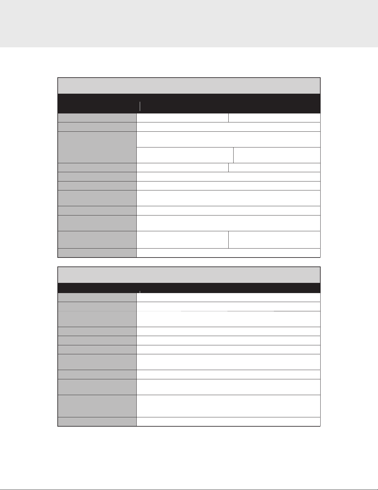
Optional Custom Front Panels - Dimensions
Note: Overlay panel must be dry, solid, straight one-piece panels. The use of multiple panel pieces to achieve the dimensions is not
recommended.
Maximum panel weight:
18" door panel - 28 lbs (12.6 kg)
24" door panel - 41 lbs (18.5 kg)
30" door panel - 54 lbs (24.5 kg)
36" door panel - 67 lbs (30.4 kg)
18” panel - 17-1/16” (43.3 cm)
24” panel - 23-1/16” (58.6 cm)
30” panel - 25-1/16” (73.8 cm)
36” panel - 35-1/16” (85.0 cm)
Custom Panel - hole locations
5-1/16”
(12.8 cm)
5-1/16”
(12.8 cm)
14-7/8”
(37.8 cm)
79-7/8”
(202.9 cm)
25-7/8”
(65.7 cm)
35-7/8”
(91.1 cm)
37-7/8”
(96.2 cm)
47-7/8”
(121.6 cm)
58-7/8”
(149.5 cm)
69-1/16”
(175.4 cm)
18” panel - 17-3/4” (45.1 cm)
24” panel - 23-3/4” (60.3 cm)
30” panel - 29-3/4” (75.5 cm)
36” panel - 35-3/4” (90.8 cm)
16

Optional Custom Front Panels - Install
In order to access the mounting holes, unsnap panel trim on both sides of door.
Panel trim
17
Mounting Screw
locations

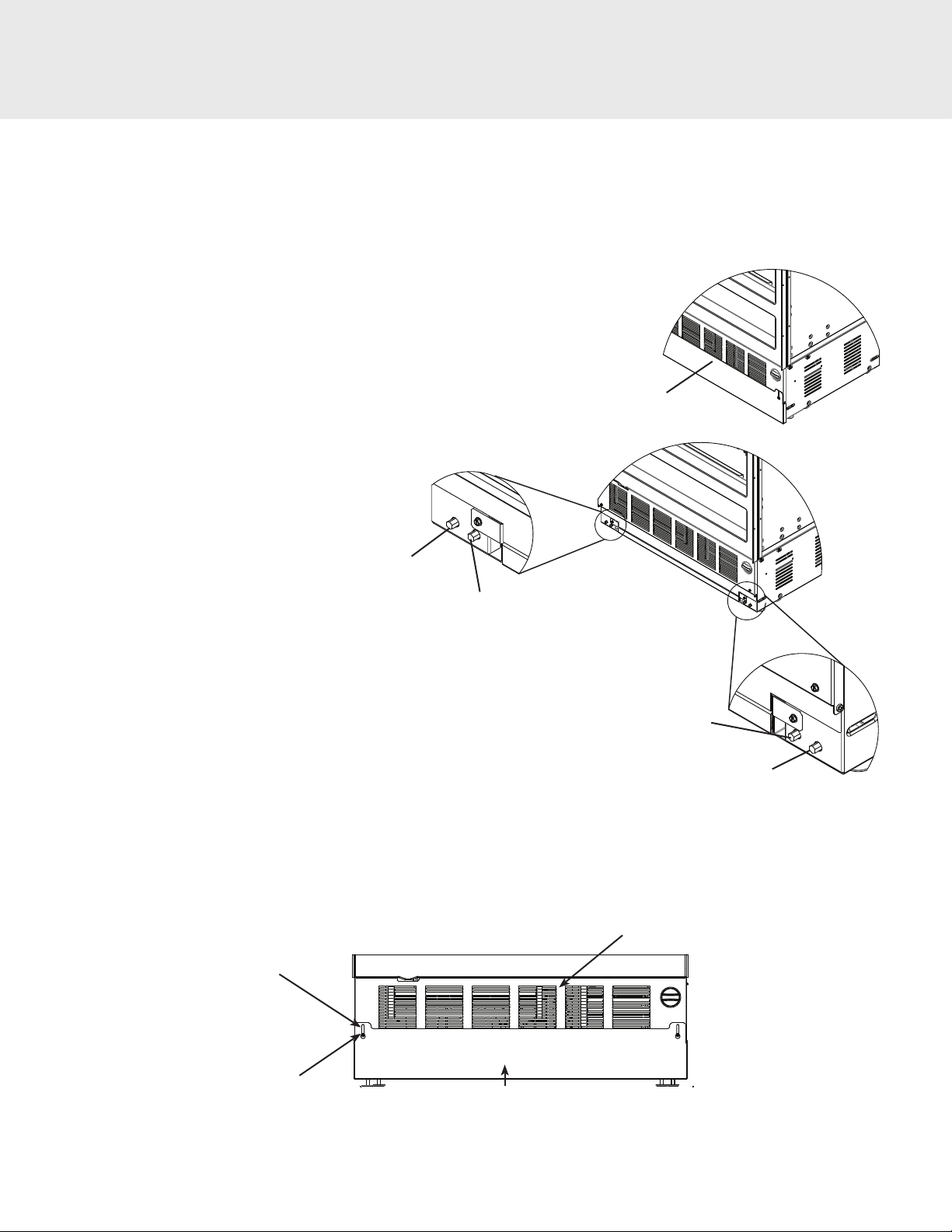
Water Line Installation
Appliance is top heavy and tips easily when not
completely installed. To avoid a hazard due to
instability of the appliance, it must be installed
according to the instructions including the anti-tip
bracket
Ensure you have approximately 6 ft. (1.8 m) of 1/4" (6
mm) copper tubing available at the right rear side of
the refrigerator.
Open door
Remove the kickplate by removing the screws on
each side. Remove the access panel by unsnapping
the panel from the frame.
WARNING
TIP OVER HAZARD
18
access panel
kickplate

Water Line Installation
With the refrigerator in line with the cutout, but outside
of the cabinetry, insert the copper tubing through the
indicated hole.
Push the copper tubing through the machine
compartment until it comes out the front side of the
refrigerator.
Roll the refrigerator into place in the cabinet cutout.
Coil the copper tubing in a vertical loop so that the
end of the copper tube faces toward the rear of the
refrigerator.
Install nut and ferrule over end of copper tube. Insert
the end of the copper tube into the water valve.
Tighten the nut until the ferrule ts snug on the copper
tube.
Turn on water supply and check for leaks. Repair leaks
if found.
Level the refrigerator, replace the access panel and
kickplate.
Water valve
19
Copper
tubing
Leveling Unit
Once the unit is in position, height adjustment can be made from
the front. Remove access panel just below the water lter. Using a
5/16" hex drive, turn clockwise to raise the unit or counterclockwise
to lower. Use the lowest torque setting when using a power drill.
Do not turn the leveling legs by hand. When the unit is properly
leveled, door/drawer adjustments are less likely to be necessary.
IMPORTANT NOTE: Level the unit to the oor, not surrounding
cabinetry. This could a ect the operation of the unit, such as door
closing.
Front Panel
B
Left Front
Adjustment
Left Rear
Adjustment
Right Rear
Adjustment
Right Front
Adjustment
A
Kickplate Installation
After the unit has been adjusted to the proper height, place the kickplate on the lower front with the adjustment screws in the slots. Let the
kickplate drop until it hits the oor. Tighten the screws.
Front of unit
Adjustment slot
Adjustment screws
kickplate
20

Flush Mount Side Trim
After the unit has been placed in the cutout, leveled and all connections completed, the unit will need to be fastened to the cabinetry. Open the
door. Using the at wood screws, fasten the unit to the cabinetry on both sides. NOTE: Only use the screws provided and use caution when
installing the fastening screws to prevent scratching the frame. Use a 3" Phillips driver to prevent damage.
Flat wood screws
Door Panel Adjustments
On the side of each panel, at the top and bottom there is a vertical
slot with a cam spacer for front to back adjustments. In the center,
there is a horizontal adjustment for up and down. All hardware
needs to be loosened before adjusting.
Vertical slot for front
to back adjustment
Horizontal slot for up
and
down adjustment
Push decorative magnetic trim into a xed side trim on both
sides of unit until the trim is all the way in and stops. Close
the door.
21

Door Stop Adjustment
Your refrigerator is factory set at a 90o degree opening. The 90 degree door stop opening is shown in the illustration below with the long end of
the door stop facing away from the door. To change to 105
and door stop. Rotate the door stop 180
For additional information on the door stop adjustment, visit the product information tab for 7 Series Bottom Mount Refrigerators online at
vikingrange.com in the US or brigade.ca in Canada.
o
degrees so that the shorter end faces away from the door. Replace door stop and screws.
o
door stop, locate the door stop on top of the door hinge. Remove the two screws
Long end of door stop
Door Stop
Remove screws and
door stop
Rotate 180o degrees Replace door stop and
screws
22

Water Filter System Speci cation and Performance Data Sheet
This system has been tested according to NSF/ANSI 42/53 for reduction of the substances listed below. The concentration of the indicated
substances in water entering the system was reduced to a concentration of less than or equal to the permissible limit for water leaving the
system, as speci ed in NSF/ANSI 42/53.* (100% safety factors built-in for unmetered usage for health claims only.)
Contaminant
Reduction
Chlorine Taste and
Odor
Nominal Particulate
Class I, >0.5 to <
1.0 μm
Asbestos 96 MF/L 107 to 108 bers/L;
Atrazine 0.010 mg/L 0.009 mg/L + 10% 89.3% 0.001 mg/L 0.003 mg/L N/A J-00056512
Cyst* 122,500
Lead @ pH 6.5 0.153 mg/L 0.15 mg/L + 10% 99.3% 0.001 mg/L 0.010 mg/L N/A J-00056515
Lead @ pH 8.5 0.150 mg/L 0.15 mg/L + 10% 99.3% 0.001 mg/L 0.010 mg/L N/A J-00058784
Lindane 0.002 mg/L 0.002 mg/L + 10% 97.8% 0.00004 mg/L 0.0002 mg/L N/A J-00058969
Mercury @ pH 6.5 0.006 mg/L 0.006 mg/L + 10% 95.0% 0.0003 mg/L 0.002 mg/L N/A J-00058785
Mercury @ pH 8.5 0.006 mg/L 0.006 mg/L + 10% 88% 0.0007 mg/L 0.002 mg/L N/A J-00058783
Toxaphene 0.015 mg/L 0.015 mg/L + 10% 93.2% 0.001 mg/L 0.003 mg/L N/A J-00056531
Turbidity 10.8 NTU 11 + 1 NTU 98.7% 0.153 NTU 0.5 NTU N/A J-00058972
Average
In uent
2.0 mg/L 2.0 mg/L + 10% 97.5% 0.05 mg/L N/A > 50% J-00056501
13,666,667
pts/mL
cysts/L
NSF Speci ed Chal-
lenge
Concentration
At least 10,000
particles/mL
bers greater than
10μm in length
Minimum 50,000
cysts/L
Avg %
Reduction
98.9% 143,333
>99% <1 MF/L N/A > 99% J-00056511
99.99% 1 cyst/L N/A > 99.95% J-00056513
Average
Product Water
Concentration
pts/mL
Max Permissible
Product Water
Concentration
N/A > 85% J-00056506
N S F
Reduction
Requirements
*Based on the use of Cryptosporidium parvum oocysts
NSF Test
Report
Operating Speci cations
Capacity: Certi ed for up to 750 gallons (2,838 L); up to nine months
Pressure Requirement: 20 - 120 psi (1.4 - 8.2 bar)
Temperature: 33-100º F (0.6 - 37.8º C)
Flow rate: 0.78 gpm (2.9 l/min.)
Check for compliance with the state and local laws and regulations.
Note: While the testing was performed under standard laboratory conditions, actual performance may vary.
Must be installed and operated in accordance with manufacturer’s recommended procedures and guidelines. Installation instructions, parts
and service availability, and standard warranty are included with the product when shipped. This drinking water system must be maintained
according to manufacturer’s instruction, including replacement of lter cartridges.
Manufactured by:
3M Puri cation Inc.
400 Research Parkway
Meriden, CT 06770
System tested and certi ed by NSF International against
Standard 42 for the reduction of chlorine taste and odor,
particulate Class I and Standard 53 for the reduction
of Lead, Lindane, Atrazine, Mercury, Toxaphene, Cyst,
Turbidity, and Asbestos.
23

Performance Checklist
—Verify cabinet size.
— Verify electrical supply and water supply (if applicable).
— Install anti-tip device(s) and verify unit is secure.
— Position unit in cutout, level at desired height and secure unit.
—Plug-in unit and verify operation.
—Connect water supply (if applicable).
• Verify icemaker ll tube is properly inserted.
• Verify icemaker bail arm is down.
• Verify dispenser operation (if applicable).
Verify Operations
Control Panel
VRI/FRI/MVRI 7240 / 7300 / 7360
—Align/square door(s).
— Verify drain pan is properly installed and there are no leaks on
water connection.
—Install kickplate.
— Remove internal packaging and labels and wipe unit down.
VFI/FFI/MVFI 7240 / 7300 / 7360
VFI/FFI/MVFI7180
24

Verify Operations
1. When unit is rst plugged in, the display will ash. "PL". Press the refrigerator select button twice to initiate display.
2. Verify unit is not in Sabbath Mode.
If in Sabbath Mode:
A. The Sabbath Mode will disable the interior lights, display (except SAB indicator, temperature and compartment indicator) and alarm. If
in Sabbath Mode, SAB will be lit.
To exit the Sabbath Mode:
B. Press and hold SAB button for 3 seconds
3. Verify unit is not in Showroom Mode.
If in Showroom Mode:
A. The Showroom Mode will disable the refrigerator system but all other functions are normal. These include lights and control. If the
refrigerator is in Showroom Mode, SHOW ROOM will be lit.
To exit Showroom Mode:
B. To deactivate Showroom mode, simultaneously press and hold the VAC key and the ALARM key for 3 seconds.
4. All models are set at 39° F and 0° F for the refrigerator and freezer respectfully - factory setting. Wait 24 hours before changing
temperatures.
Service & Registration
If service is required, call your authorized service agency.
Have the following information readily available.
• Model number
• Serial number
• Date purchased
• Name of dealer from whom purchased
Clearly describe the problem that you are having. If you are unable to obtain the name of an authorized service agency, or if you continue to
have service problems, contact Viking Range, LLC at 1-888-(845-4641), or write to:
VIKING RANGE, LLC
PREFERRED SERVICE
111 Front Street
Greenwood, Mississippi 38930 USA
Record the following information indicated below. You will need it if service is ever required.
The serial number and model number for your appliance are located on the identi cation plate mounted behind the top light.
Record the information indicated below. You will need it if service is ever required.
Model number .................................................................................................................................................................................................................................................
Serial number ..................................................................................................................................................................................................................................................
Date of purchase .............................................................................................................................................................................................................................................
Date installed ..................................................................................................................................................................................................................................................
Dealer’s name ...................................................................................................................................................................................................................................................
Address ..............................................................................................................................................................................................................................................................
................................................................................................................................................................................................................................................................................
If service requires installation of parts, use only authorized parts to insure protection under the warranty.
KEEP THIS MANUAL FOR FUTURE REFERENCE.
25

26

27

Viking Range, LLC
111 Front Street
Greenwood, Mississippi 38930 USA
(662) 455-1200
For product information,
call 1-888-(845-4641)
or visit our web site at vikingrange.com
062223-000B EN
U
U
L
L
C
(071519)
 Loading...