

Viking BQCO53T1 Installation Manual

F20291B EN
(032608J)
Viking Range Corporation
111 Front Street
Greenwood, Mississippi 38930 USA
(662) 455-1200
For product information,
call 1-888-VIKING1 (845-4641)
or visit the Viking Web site at
vikingrange.com
Viking Installation Guide
BQCO “T” Series Cart with Outdoor Oven
3
Description BQCO53T1
Overall width With shelves extended - 85-1/4” (216.5 cm)
Overall height 37-5/8” (95.6 cm)
Overall depth To edge of side- 28-9/16” (72.5 cm)
To end of handle bracket - 31-1/16” (78.9 cm)
With door open - 51-7/8” (131.8 cm)
Gas requirements Natural: Standard residential 1/2” (1.3 cm) ID gas service line
LP/Propane: Equipped with high capacity hose/regulator assembly for connection to standard 5gal,
20 lb. Propane gas cylinder with Type 1, QCC-1 connection or standard residential 1/2”
(1.3 cm) ID gas service line
Units are ordered either Natural or LP. Gas Conversion kits are required to convert from one gas to
another. Contact dealer for proper conversion kit. Gas conversions should only be done by an
authorized service technician.
Bake burner rating 20,000 BTU Nat/LP
Oven interior Dimensions Width - 18-1/8” (46.1 cm)
Height - 12-7/16” (31.6 cm)
Depth- 18-3/4” (47.6 cm)
Overall- 2.45 cu. ft.
Approximate shipping wt. 319 lbs. (143.5 kg)
Specifications
BEFORE INSTALLING GRILL TO CART: Remove drip tray, grill grates, flavor grids, and warming racks from the grill.
To remove side shelves:
The side shelves on the cart can be removed if needed. This must be done before installing the grill on the cart. With
the shelf in the up position, remove the screws in the shelf support bracket. This will allow you to remove both the
brackets and the shelf.
2
IMPORTANT: PLEASE READ AND FOLLOW
1. Before beginning, please read these instructions completely and carefully.
2. Do not remove permanently affixed labels, warnings, or plates from product. This may void the warranty
3. Please observe all local and national codes and ordinances.
4. The installer should leave these instructions with the consumer who should retain for local inspector’s use and for
future reference
Installation must conform with local codes or in the absence of codes, the National Fuel Gas Code, ANSI Z223.1. In
Canada: Installation must be in accordance with the current CAN/CGA-B149.1, Natural Gas Installation Code or
CAN/CGA-B149.2, Propane Installation Code and/or local codes.
NOTE: THE BQCO “T” SERIES CART WITH OUTDOOR OVEN CANNOT BE INSTALLED IN A BUILT-IN
APPLICATION.
If you smell gas:
1. Shut off gas to the appliance.
2. Extinguish any open flame.
3. Open lid.
4. If odor continues, immediately call your gas supplier or your
fire department.
1. Do not store or use gasoline or other flammable vapors
and liquids in the vicinity of this or any other appliance.
2. Any LP cylinder not connected for use shall not be stored
in the vicinity of this or any other appliance.
If not installed, operated and maintained in
accordance with the manufacturer’s instructions, this
product could expose you to substances in fuel or
fuel combustion which can cause death or serious
illness and which are known to cause cancer, birth
defects or other reproductive harm.
For example, benzene is a chemical which is
part of the gas supplied to the cooking
product. It is consumed in the flame during
combustion. However, exposure to a small
amount of benzene is possible if a gas leak
occurs. Formaldehyde and soot are byproducts of incomplete combustion. Properly
adjusted burners with a bluish rather than
yellow flame minimize incomplete combustion.
FOR YOUR SAFETY
WARNING
FOR YOUR SAFETY
EXCESSIVE WEIGHT HAZARD
Use two or more people to move and install this
unit. Failure to follow this instruction can result in
back or other injury.
WARNING
support bracket
screws
Shelf
adjustment
screw
Front View
Supports
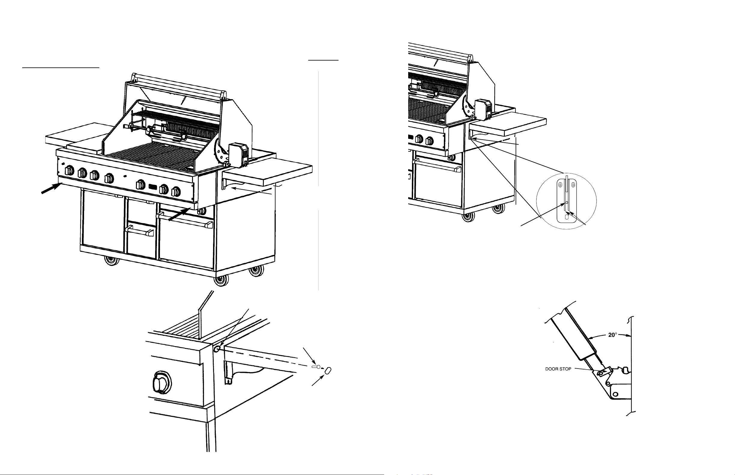
Leveling the Side Shelves
To level the side shelves, lift the shelf so that the
shelf adjustment screw is visible between the two
supports on the shelf brackets. Turn the screw with
a 3/32” (.2 cm) allen wrench counter clockwise to
raise the shelf and clockwise to lower the shelf.
Door Removal
1. Open the door approximately 20othen
slowly pull upward until the door stop pops
out of the door socket. Gently close the
door until the door rests against one of the
stop notches. Slide the door completely
from the hinge arms.
2. To replace the door, place the hinge arms
into the door sockets. Slide the door down
close to the hinge stops and release the
pressure from the stop notches. Slowly slide
the door down completely allowing the
hinge stops to retract into the door socket.
support bracket
screws
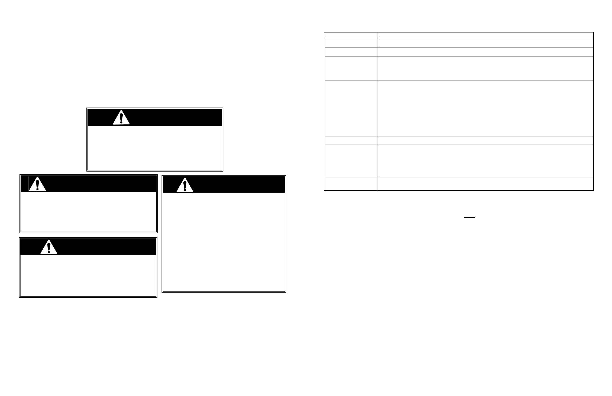
To mount grill to cart:
Always wear gloves when handling the gas grill. Although the grill is deburred prior to shipment, some edges may
still be sharp enough to cause injury during handling. With a minimum of two (2) people, place the grill in the cart with
about 3 to 4 inches hanging out the front making sure that the male fitting on the bottom of the grill is inside the cart.
Push the grill back until the front sides of the cart are flush with the back of the landing ledge on the grill. Be careful:
the grill unit is very heavy!
Attaching the grill to the cart
Once the grill has been mounted on
the cart, the back of the landing ledge
should be flush with the front sides of
the cart. The 5/8” (1.6 cm) hole on
the top front corners of the cart
should be aligned with the receiving
holes in the grill heat shields. If your
grill does not have the receiving holes
in the heat shield, you will need to
drill them out with a 9/64” (.14 cm)
drill bit. With the grill and cart
mounted together, place the drill bit
in the 5/8 hole and center in the
1/4”x3/8” slot. Drill through the heat
shield. Take the #10X3/4” (1.9 cm)
sheet metal screws (A) supplied with
the cart and attach the cart sides to
the grill. After securing the grill to the
cart, snap the hole covers (B) supplied
with the cart into the 5/8” (1.6 cm)
holes in the cart corners.
5/8” (1.6 cm) dia. hole
(A) #10X3/4” (1.9 cm)
sheet metal screw
(B) 5/8” (1.6 cm)
hole cover
5
4
 Loading...