


Vigo VG6063BNCL42W, VG6063CHCL42WS, VG6063BNCL47WS, VG6063BNCL47, VG6063BNCL42WS Specifications
...VIGO INDUSTRIES INSTALLATION GUIDE FOR
SHOWER ENCLOSURE (MODEL VG06063)
!SAFETY PRECAUTIONS
This Installation Guide uses the following symbols to indicate important information. Always observe the instructions indicated by these symbols.
!WARNING
Instructions that, if ignored, could result in death or serious personal injury caused by incorrect handling or installation of the product. These instructions must be observed for safe installation.
!CAUTION
The instructions for the following unit is based off of the Vigo brand shower base. The instructions can not be provided for any other installation other than that of the Vigo brand. The warranty will be voided if the following was not performed properly.
IMPORTANT
Maintenance and other important non-personal injury and non-material damage instructions or statements that should be observed.
It is highly advised to dry fit the unit prior to any installation.
*VIGO reserves the right to modify/update all hardware and glass components based on bettering the product for the end user's experience. If you have any questions contact VIGO Tech Support at 1-866-591-7792.
1
REV 1 - 8/9/18

MODEL VG06063 GEMINI
INSTALLATION INSTRUCTIONS FOR SHOWER ENCLOSURE
PLEASE READ INSTRUCTIONS BEFORE PROCEEDING
|
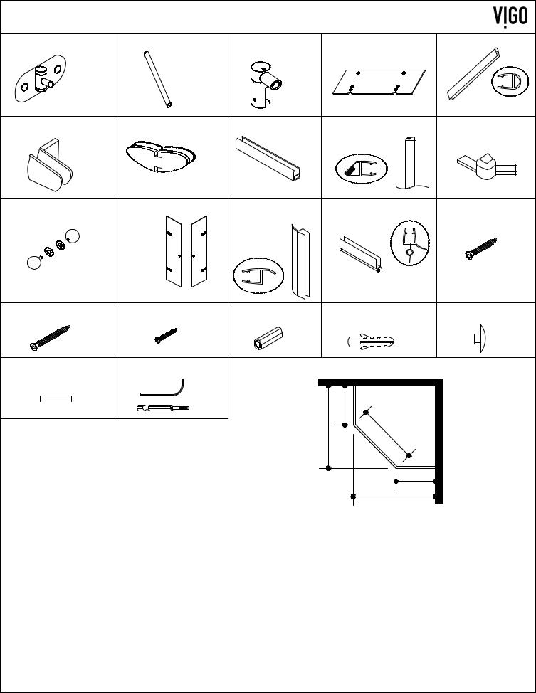
Parts List |
12. |
Door (2 pc) |
|
|
1. |
Wall connector (2pc) |
13. |
Door side seal strip (2pc + 1pc is extra) |
|
2. |
Structural arm (2pc) |
14. |
Door bottom seal strip (2pc + 1pc is extra) |
|
3. |
Support assembly (2pc) |
15. |
Hex screws 1 1/8" (4pc) |
|
4. |
Side glass panel with hinge slots (2pc) |
16. |
Hex screws 1 5/8" (8pc) |
|
5. |
Side seal strip (2pc) |
17. |
Phillips screws 3/4" (8pc) |
|
6. |
Glass support (4pc) |
18. |
Plastic anchors green (12pc) |
|
7. |
Hinge (4pc) |
19. |
Plastic anchors white (8pc) |
|
8. |
Bottom rail (3 pc) |
20. Hex screw covers (32pc) |
|
|
9. |
Door magnetic seal strip (2pc) |
21. Clear PVC shim (1pack) |
|
1 |
10. Bottom corner joint (2 pc) |
22. Allen key pack (1 pack) |
||
|
11. Handle assembly (2 sets) |
|
|
|
2 |
|
|
|
|
3 |
|
|
|
18 |
4 |
|
|
|
|
|
|
|
15 |
|
5 |
|
|
|
|
|
|
|
19 |
|
|
|
|
|
|
6 |
|
|
9 |
12 |
11 |
|
|
13 |
|
||
|
|
|
|
7 |
|
4 |
13 |
19 |
|
||
|
|
14 |
|
8 |
|
|
16 |
18 |
|
|
|
17 
 10
10
GLASS THICKNESS 3/8"
NOTE: INSTALLATION MUST BE DONE BY A QUALIFIED, LICENSED PROFESSIONAL. |
2 |
1. |
WALL CONNECTOR |
2. STRUCTURAL ARM |
3. SUPPORT |
|
4. SIDE PANEL |
5. SIDE SEAL STRIP |
|
|
98001 |
|
|
ASSEMBLY |
|
97001-42 |
|
|
|
98002-42 |
|
98003 |
|
97001-47 |
96001 |
|
|
98002-47 |
|
|
|
|
|
6. GLASS SUPPORT |
7. HINGE ASSEMBLY |
8. |
BOTTOM RAIL |
9. MAGNETIC SEAL STRIP |
10.CORNER JOINT |
||
|
98004 |
98015 |
|
95001-42 |
|
96011 |
94001 |
|
|
|
|
95001-47 |
|
|
|
|
|
|
|
|
|
|
|
11. |
DOOR HANDLE |
12. DOOR |
13. DOOR SIDE SEAL |
14. DOOR BOTTOM SEAL |
15. HEX SCREW 1 1/8" |
||
|
ASSEMBLY |
97002-12 |
|
STRIP |
|
STRIP |
|
|
98014 |
|
|
|
|
|
|
|
|
|
|
|
|
|
|
|
|
|
|
|
|
96004 |
96035 |
|
|
|
|
96003 |
|
|
|
16. HEX SCREW 1 5/8" |
17. PHILLIPS SCREW 3/4" |
18. PLASTIC ANCHOR |
|
19. PLASTIC ANCHOR |
20. HEX SCREW COVER |
||
|
98039 |
98033 |
|
98037 |
|
98038 |
96040 |
21. CLEAR PVC SHIM |
22. ALLEN KEY PACK |
|
|
|
|
|
|
|
MISC |
MISC |
|
|
|
|
|
|
|
|
|
|
|
B |
|
|
|
|
|
|
A |
C |
|
|
|
|
|
|
|
|
|
|
|
|
|
|
|
B |
|
|
|
|
|
|
|
A |
|
*- GLASS AND HARDWARE ONLY (FULLY INSTALLED)
MODEL |
DIM. "A" |
DIM. "B" |
DIM. "C" |
HEIGHT |
#4- SIDE GLASS |
#12DOOR (97002) |
DOOR OPENING |
|
|
|
|
|
PANEL (97001) |
|
WIDTH |
|
|
|
|
|
|
|
|
47 X 47 |
45 5/8" |
26 5/8" |
26 7/8" |
73 3/8" |
26"x71 5/8" |
12 5/8"x70 3/8" |
26 1/2" |
|
|
|
|
|
|
|
|
42 X 42 |
40" |
21 1/8" |
26 7/8" |
73 3/8" |
20 1/2"x71 5/8" |
12 5/8"x70 3/8" |
26 1/2" |
|
|
|
|
|
|
|
|
A, B & C DIMENSIONS WERE MEASURED AFTER SHOWER ENCLOSURE WAS COMPLETELY
INSTALLED
 Product lines may change, contact your Vigo representative at 1-866-591-7792 or visit our website at www.vigoindustries.com for the most up to date product line information.
3
MODEL VG06063
! WARNING
WE STRONGLY RECOMMEND THAT A LICENSED PROFESSIONAL INSTALL THIS SHOWER ENCLOSURE AND INCLUDE THE ASSISTANCE OF A SECOND PERSON TO INSTALL THE DOOR UNIT.
INSTALLATION OF THE SHOWER DOORS BY AN INEXPERIENCED PERSON MAY RESULT IN GLASS BREAKAGE AND, CONSEQUENTLY, CAUSE PERSONAL INJURY OR DEATH.
-Handle fragile items with care to prevent personal injury or material damage.
-The glass panels are tempered and cannot be cut. Never attempt to do so.
-Always rest glass on a level surface
BEFORE STARTING
Compare items on your invoice with what you have received. Carefully review the Packing List on page 2. If any items are missing contact Vigo Industries at 1-866-591-7792. Please check our website at www.vigoindustries.com for additional information or instructional videos.
REQUIRED TOOLS
Square and/or Phillips #1 and #2 screwdriver
Flat head screwdriver
Electric drill plus 1/32", 3/32", 1/8" and 3/16" drill bit (depending on wall)
Level
Measuring tape
Pencil (non-permanent)
Clear silicone caulking
Utility knife
!WARNING
Handle fragile items with care to prevent injury or material damage.
Glass on panels and doors is tempered glass and must never be cut to prevent personal injury.
IMPORTANT
Fiberglass, acrylic or sheetrock construction might not be sufficiently strong enough to support the shower door enclosure. You should use the wood framing studs from behind the face edge of the stall to provide a secure mounting to the door. Apply a bead of silicone between the walls and base of the stall.
For optimum performance, you should install the shower door perfectly level on a level surface. Failure to do so will lead to water leakage and potential property damage.
When installing use heavy duty gloves.
IMPORTANT:
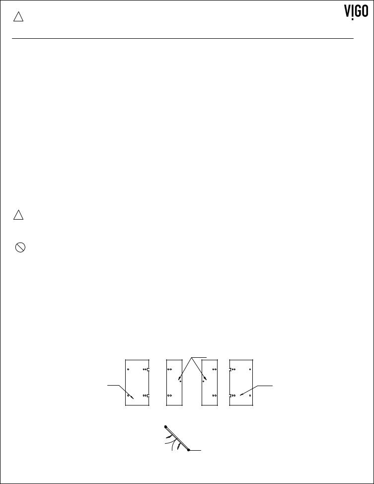
THE CLEAR GLASS MODEL HAS A REVERSIBLE DOOR AND CAN BE INSTALLED TO THE RIGHT OR LEFT SIDE. (SEE CONFIGURATION DIAGRAM BELOW)
12
4 |
4 |
SIDE GLASS |
|
DOOR PANELS |
SIDE GLASS |
||
PANEL |
|
|
|
|
PANEL |
|
|
|
|
|
|
|
|
|
|
|
|
|
|
|
|
|
|
|
|
|
|
|
|
|
|
|
|
|
|
FIG. 1A (GLASS CONFIGURATION DIAGRAM)
4
MODEL VG06063
PREPARATION STEPS TO FOLLOW BEFORE INSTALLATION
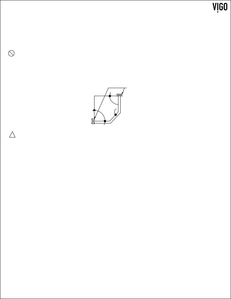
1.Remove the plastic layer from the base border (if needed). Do NOT remove the plastic layer off the plastic platform of the base.
2.Properly apply silicone to the wall and base joints.
3.Make sure to read corresponding base instructions carefully prior to install on the Vigo Brand Shower Door System. Failure to do so can cause water leakage and bodily harm.
IMPORTANT
To prevent damage to the finish, you should protect the shower cabin bottom with a cardboard protector before beginning the installation.
Ensure that there is sufficient structural support behind the shower wall to hold the weight of the shower door. If there is insufficient support, then reinforce the shower walls with wooden studs prior to shower door installation. [SEE FIG.1]
STUD


FIG.1
!CAUTION
GASKETS NEED TO BE IN BETWEEN ALL GLASS AND METAL CONTACT. FAILURE TO DO SO CAN LEAD TO BREAKAGE AND POTENTIAL BODILY HARM.
5
MODEL VG06063
INSTALLATION STEPS
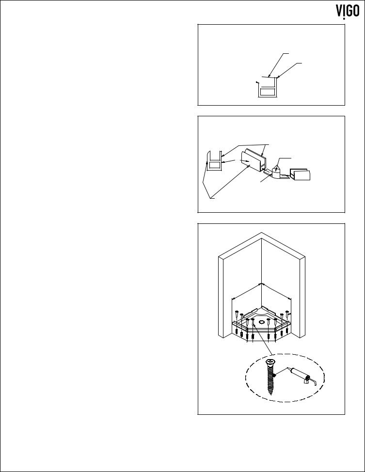
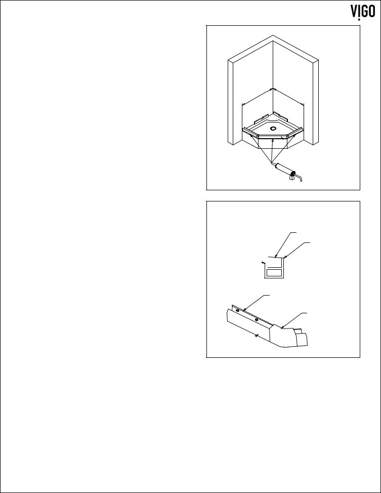
A.INSTALLING THE BOTTOM RAIL
1.Remove the aluminum cover from the front piece of the bottom rail by sliding it out.
A1
ALUMINUM COVER
INSIDE
OUTSIDE 

2.Remove top of the corner joint. Slide the bottom corner joint (2 pieces) (#10) onto the bottom rail (3 pieces) (#8).
3.Align the bottom rail and corner joint to the desired position on the shower base. Prior to drilling, dry fit everything making sure that everything is straight, level and plum. Distance "A" and "B" should be the same distance from the corner of the wall to the bottom rail. Pre-drill for sinkers and tap sinkers. Cut excess sinker off with hacksaw or sharp blade. Dip screws in silicone and screw corner joints and rails down. Silicone tops of screws.
A2
|
THIS EDGE LOOKS |
|
|
INSIDE OF THE SHOWER |
|
8 |
TOP REMOVES TO |
|
INSTALL 3/4" SCREW |
||
|
10
THIS EDGE LOOKS
OUTSIDE OF THE SHOWER
A3
A |
B |
 17
17
6
MODEL VG06063
4.Seal the bottom rail with clear silicone caulk and center its sides to the base.
5.Clip the aluminum cover to the front piece of the bottom rail making sure the lower side faces the inside of the shower. Silicone the underneath portion of the corner joint caps and put them on the corner joints.
A4
A |
B |
 8
8
A5
ALUMINUM COVER
INSIDE
OUTSIDE 

INSIDE
CORNER JOINT
CAP
OUTSIDE 
7
MODEL VG06063
 Loading...