

Page 1

Service Manual
ViewSonic VX715-1
Model No. VS10057
17” Color TFT LCD Display
ViewSonic
(VX715_SM_829 Rev. 1b Aug. 2004)
381 Brea Canyon Road, Walnut, California 91789 USA - (800) 888-8583
Page 2
Copyright
Copyright
2004 by ViewSonic Corporation. All rights reserved. No part of this publication may be
¤
reproduced, transmitted, transcribed, stored in a retrieval system, or translated into any language or
computer language, in any form or by any means, electronic, mechanical, magnetic, optical, chemical,
manual or otherwise, without the prior written permission of ViewSonic Corporation.
Disclaimer
ViewSonic makes no representations or warranties, either expressed or implied, with respect to the
contents hereof and specifically disclaims any warranty of merchantability or fitness for any particular
purpose. Further, ViewSonic reserves the right to revise this publication and to make changes from time
to time in the contents hereof without obligation of ViewSonic to notify any person of such revision or
changes.
Trademarks
Optiquest is a registered trademark of ViewSonic Corporation.
ViewSonic is a registered trademark of ViewSonic Corporation.
All other trademarks used within this document are the property of their respective owners.
1a
1b
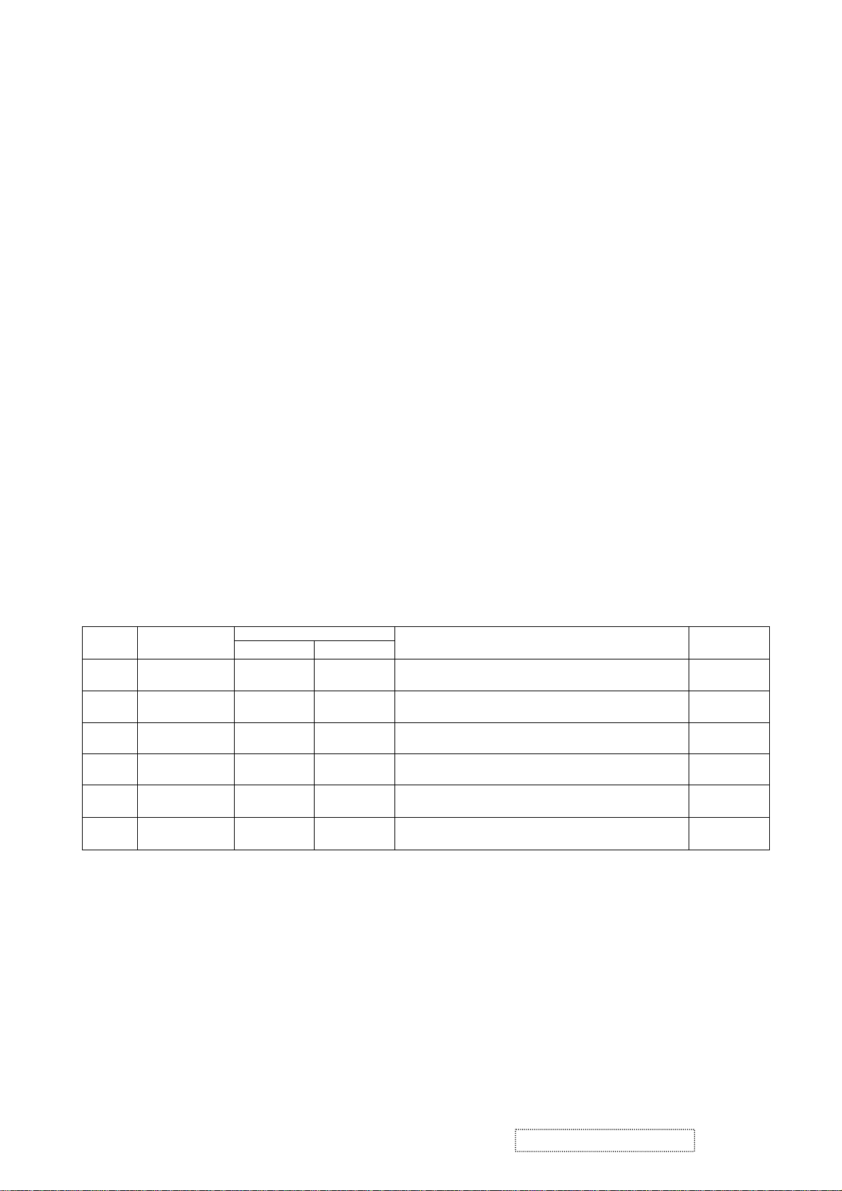
Revision History
Documents Number
DCN Number ECR Number
28/04/04
04/08/04
286
4
4646
Description of Changes EditorRevision SM Editing Date
Initial Release
ECR Change to 2nd Source Panel (Hydis Panel + MST Scalar) A. Lu
A. Lu
ViewSonic Corporation Confidential
i
-
Do Not Copy VX715
Page 3

TABLE OF CONTENTS
1. Precautions and Safety Notices
2. Specification
3. Front Panel Function Control Description
4. Circuit Description
5. Adjusting Procedure
6. Trouble Shooting Flow Chart
7. Recommended Spare Parts List
8. Exploded Diagram And Spare Parts List
9. Block Diagram
10. Schematic Diagrams
11. PCB Layout Diagrams
1
2
11
18
21
30
31
42
44
45
52
ViewSonic Corporation Confidential
ii
-
Do Not Copy VX715
Page 4

1. Precautions and Safety Notices
1. SAFETY PRECAUTIONS
This monitor is manufactured and tested on a ground principle that a user’s safety comes first. However, improper
use or installation may cause damage to the monitor as well as the user. Carefully go over the following
WARNINGS before installing and keep this guide handy.
WARNINGS
.
This monitor should be operated only at the correct power sources indicated on the label on the rear end of the
.
.
.
.
.
.
monitor. If you’re unsure of the power supply in your residence, consult you local dealer or power company.
Do not try to repair the monitor your self as it contains no user-serviceable parts. This monitor should only be
repaired by a qualified technician.
Do not remove the monitor cabinet. There are high-voltage parts inside that may cause electric shock to human
bodies, even when the power cord is unplugged.
Stop using the monitor if the cabinet is damaged. Have it checked by a service technician.
Put your monitor only in a clean, dry environment. If it gets wet, unplug the power cable immediately and
consult your service technician.
Always unplug the monitor before cleaning it .Clean the cabinet with a clean, dry cloth. Apply non-ammonia
based cleaner onto the cloth, not directly onto the glass screen.
Keep the monitor away from magnetic objects, motors, TV sets, and transformer.
Do not place heavy objects on the monitor or power cord.
2. PRODUCT SAFETY NOTICE
Many electrical and mechanical parts in this chassis have special safety visual inspections and the protection
afforded by them cannot necessarily be obtained by using replacement components rated for higher voltages,
wattage, etc. Before replacing any of these components read the parts list in this manual carefully. The use of
substitute replacement parts which do not have the same safety characteristics as specified in the parts list may
create shock, fire ,or other hazards.
3. SERVICE NOTES
1. When replacing parts or circuit boards, clamp the lead wires around terminals before soldering.
2. When replacing a high wattage resistor(more than 1W of metal oxide film resistor) in circuit board, keep
the resistor about 5mm away from circuit board.
3. Keep wires away from high voltage, high temperature components and sharp edges.
4. Keep wires in their original position so as to reduce interference.
5. Please refer to the user's manual for operating instructions.
ViewSonic Corporation Confidential
1
-
Do Not Copy VX715
Page 5

2. Specification
2.1 PRODUCT SPECIFICATIONS
LCD Panel 17.0” TFT
Power Management Energy Star compliant VESA
DPMS compatible
<1 W
Recommend Resolution 1280 x1024@60Hz
Pixel Dimension 0.264(H) x 0.264(V)mm
LCD Display Color 16.2M Colors (6+2FRC bit)
Viewing Angle Horizontal: 150 deg
Vertical: 130 deg
Contrast Ratio 450:1 (Typ.)
Brightness 300 cd/㎡(Typ.)
Response Time Tr Tf = 16ms
Active Display Area 337.920(H) x 270.336(V)
+
Temperature Operating: 0°C to +40°C
Storage: -20°C to +60°C
Power Input Voltage : 90V~264V
Consumption: 35 Watts(Max.) 32 Watts(Typ.)
2.2 FACTORY SUPPORTING MODES
Primary Preset: VESA : 1280 x1024@60Hz
Timing Table : 1.640 x 350 @ 70Hz, 31.5kHz
2.640 x 400 @ 60Hz, 31.5kHz
3.640 x 400 @ 70Hz, 31.5kHz
4.640 x 480 @ 50Hz, 24.7kHz
5.640 x 480 @ 60Hz, 31.5kHz
6.640 x 480 @ 67Hz, 35.0kHz
7.640 x 480 @ 72Hz, 37.9kHz
8.640 x 480 @ 75Hz, 37.5kHz
9.640 x 480 @ 85Hz, 43.27kHz
10.720 x 400 @ 70Hz, 31.5kHz
11.800 x 600 @ 56Hz, 35.1kHz
12.800 x 600 @ 60Hz, 37.9kHz
13.800 x 600 @ 75Hz, 46.9kHz
15.800 x 600 @ 85Hz, 53.7kHz
16.832 x 624 @ 75Hz, 49.7kHz
17.1024 x 768 @ 60Hz, 48.4kHz
18.1024 x 768 @ 70Hz, 56.5kHz
19.1024 x 768 @ 72Hz, 58.1kHz
20.1024 x 768 @ 75Hz, 60.0kHz
21.1024 x 768 @ 85Hz, 68.67kHz
22.1152 x 864 @ 75Hz, 67.5kHz
23.1152 x 870 @ 75Hz, 68.7kHz
24.1280 x 1024 @ 60Hz, 63.4kHz
25.1280 x 1024 @ 75Hz, 79.97kHz
26.1280x 720 @ 60Hz, 45kHz (HDTV)
14.800 x 600 @ 72Hz, 48.1kHz
ViewSonic Corporation Confidential
2
-
Do Not Copy VX715
Page 6
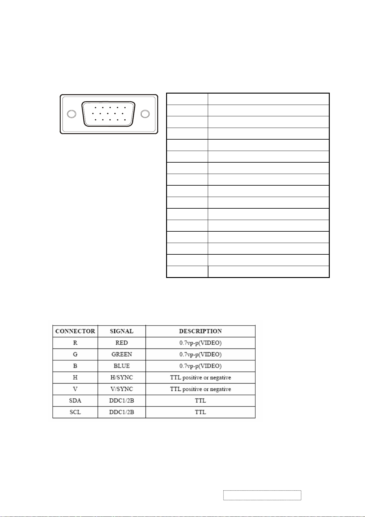
2.3 D-SUB CONNECTOR
D-SUB 15 PIN CONNECTOR
15
6
11 15
10
Pin Number Pin Function
1 Red video input
2 Green video input
3 Blue video input
4 No Connection
5 Ground
6 Red video ground
7 Green video ground
8 Blue video ground
9 +5V
SIGNAL LEVEL
10 H/V sync ground
11 No connection
12 (SDA)
13 Horizontal sync (Composite sync)
14 Vertical sync
15 (SCL)
ViewSonic Corporation Confidential
3
-
Do Not Copy VX715
Page 7
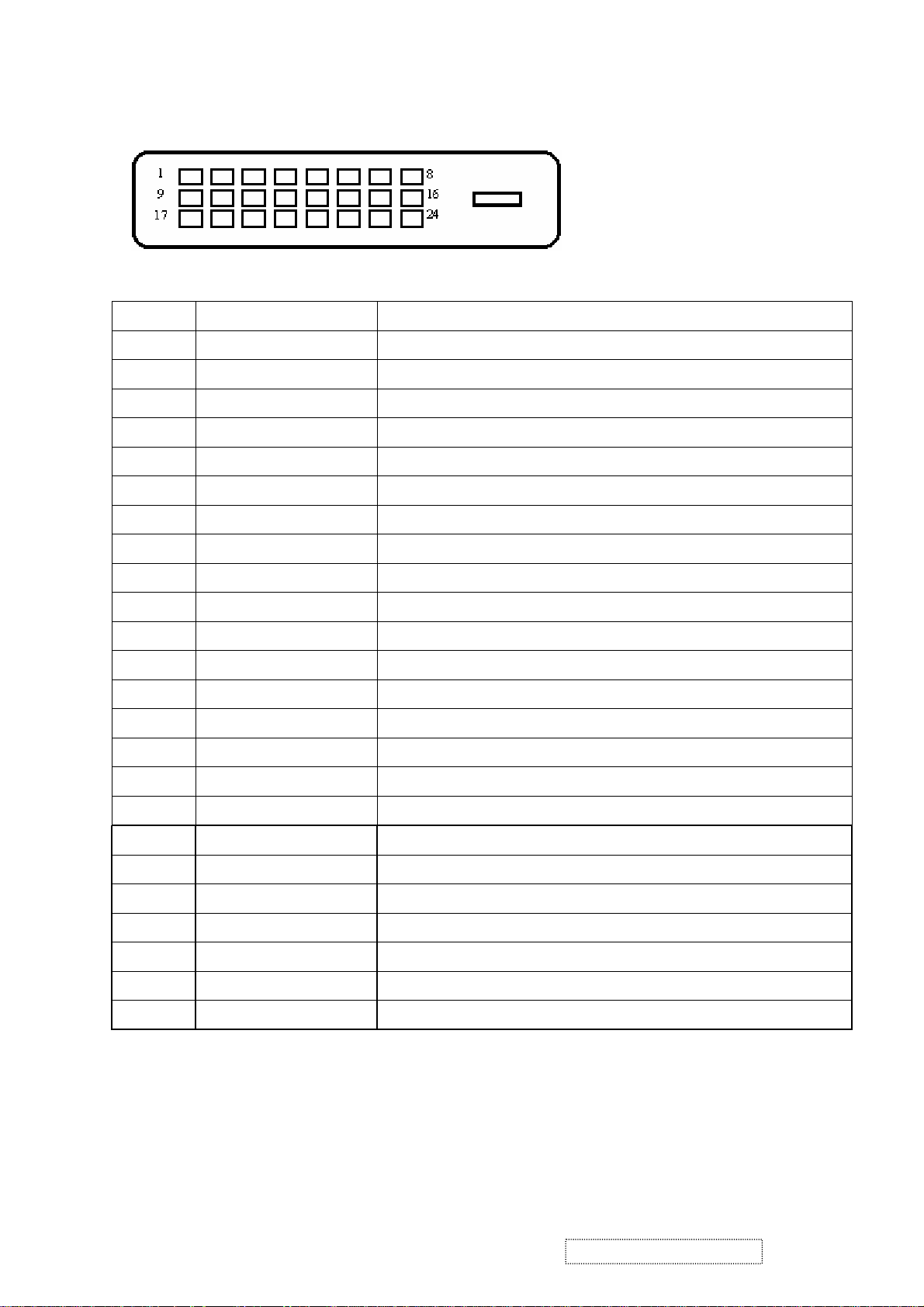
DVI 15 PIN CONNECTOR
Pin No. Signal Name Description
1 RX2- TMDS negative differential input, channel 2
2 RX2+ TMDS positive differential input, channel 2
3 GND Logic Ground
4 Reserved 4 Reserved. No connection
5 Reserved 5 Reserved. No connection
6 DDC-CLK DDC2B Clock
7 DDC-DAT DDC2B Data
8 Reserved 8 Reserved. No connection
9 RX1- TMDS negative differential input, channel 1
10 RX1+ TMDS positive differential input, channel 1
11 GND Logic Ground
12 Reserved 12 Reserved. No connection
13 Reserved 13 Reserved. No connection
14 VCCX Power
15 GND Logic Ground
16 SENS SENSE Pin, Pull High
17 RX0- TMDS negative differential input, channel 0
18 RX0+ TMDS positive differential input, channel 0
19 GND Logic Ground
20 Reserved 20 Reserved. No connection
21 Reserved 21 Reserved. No connection
22 GND Logic Ground
23 RXC+ TMDS positive differential input, reference clock
24 RXC- TMDS negative differential input, reference clock
ViewSonic Corporation Confidential
4
-
Do Not Copy VX715
Page 8

2-4 Appendix E: Analog EDID
Time: 08:16:29
Date: Mon Apr 26, 2004
______________________________________________________________________
______________________________________________________________________
VIEWSONIC CORPORATION
EDID Version # 1, Revision # 3
DDCTest For: ViewSonic VX715
______________________________________________________________________
______________________________________________________________________
128 BYTES OF EDID CODE:
0 1 2 3 4 5 6 7 8 9
________________________________________
0 | 00 FF FF FF FF FF FF 00 5A 63
10 | 19 43 01 01 01 01 01 0E 01 03
20 | 0E 22 1B 78 2A 3D 85 A3 58 46
30 | 9D 24 17 50 54 BF EF 80 81 80
40 | 71 4F 61 59 45 59 31 59 01 01
50 | 01 01 01 01 30 2A 00 98 51 00
60 | 2A 40 30 70 13 00 52 0E 11 00
70 | 00 1E 00 00 00 FF 00 50 32 31
80 | 30 34 30 31 30 30 30 30 31 0A
90 | 00 00 00 FD 00 32 55 1E 52 0E
100 | 00 0A 20 20 20 20 20 20 00 00
110 | 00 FC 00 56 58 37 31 35 0A 20
120 | 20 20 20 20 20 20 00 35
______________________________________________________________________
(08-09) ID Manufacturer Name = VSC
(11-10) Product ID Code = 4319
(12-15) Last 5 Digits of Serial Number = Not Used
(16) Week of Manufacture = 01
(17) Year of Manufacture = 2004
(10-17) Complete Serial Number = See Descriptor Block
(18) EDID Version Number = 1
(19) EDID Revision Number = 3
(20) VIDEO INPUT DEFINITION:
Analog Signal
0.700, 0.300 (1.000 Vp-p)
Separate Syncs, Composite Sync, Sync on Green
ViewSonic Corporation Confidential
5
-
Do Not Copy VX715
Page 9

(21) Maximum Horizontal Image Size = 340 mm
(22) Maximum Vertical Image Size = 270 mm
(23) Display Gamma = 2.20
(24) Power Management and Supported Feature(s):
Active Off/Very Low Power, Preferred Timing Mode
Display Type = R/G/B Color
(25-34) CHROMA INFO:
Red X - 0.637 Green X - 0.276 Blue X - 0.143 White X - 0.313
Red Y - 0.347 Green Y - 0.614 Blue Y - 0.090 White Y - 0.329
(35) ESTABLISHED TIMING I:
720 X 400 @ 70Hz (IBM,VGA)
640 X 480 @ 60Hz (IBM,VGA)
640 X 480 @ 67Hz (Apple,Mac II)
640 X 480 @ 72Hz (VESA)
640 X 480 @ 75Hz (VESA)
800 X 600 @ 56Hz (VESA)
800 X 600 @ 60Hz (VESA)
(36) ESTABLISHED TIMING II:
800 X 600 @ 72Hz (VESA)
800 X 600 @ 75Hz (VESA)
832 X 624 @ 75Hz (Apple,Mac II)
1024 X 768 @ 60Hz (VESA)
1024 X 768 @ 70Hz (VESA)
1024 X 768 @ 75Hz (VESA)
1280 X 1024 @ 75Hz (VESA)
(37) Manufacturer's Reserved Timing:
1152 X 870 @ 75Hz (Apple,Mac II)
(38-53) Standard Timing Identification:
1280 X 1024 @60Hz
1152 X 864 @75Hz
1024 X 768 @85Hz
800 X 600 @85Hz
640 X 480 @85Hz
Not Used
Not Used
Not Used
______________________________________________________________________
(54-71) Detailed Timing / Descriptor Block 1:
1280x1024 Pixel Clock: 108.00 MHz
______________________________________________________________________
ViewSonic Corporation Confidential
6
-
Do Not Copy VX715
Page 10

Horizontal Image Size: 338 mm Vertical Image Size: 270 mm
Refreshed Mode: Non-Interlaced Normal Display - No Stereo
Horizontal:
Active Time: 1280 pixels Blanking Time: 408 pixels
Sync Offset: 48 pixels Sync Pulse Width: 112 pixels
Border: 0 pixels Frequency: 63.98 KHz
Vertical:
Active Time: 1024 lines Blanking Time: 42 lines
Sync Offset: 1 lines Sync Pulse Width: 3 lines
Border: 0 lines Frequency: 60.02 Hz
Digital Separate, Horizontal Polarity (+) Vertical Polarity (+)
______________________________________________________________________
(72-89) Detailed Timing / Descriptor Block 2:
Monitor Serial Number:
P21040100001
______________________________________________________________________
(90- 107) Detailed Timing / Descriptor Block 3:
Monitor Range Limits:
Min Vertical Freq - 50 Hz
Max Vertical Freq - 85 Hz
Min Horiz. Freq - 30 KHz
Max Horiz. Freq - 82 KHz
Pixel Clock - 140 MHz
Secondary GTF - Not Supported
______________________________________________________________________
(108-125) Detailed Timing / Descriptor Block 4:
Monitor Name:
VX715
(126) No Extension EDID Block(s)
(127) CheckSum OK
ViewSonic Corporation Confidential
7
-
Do Not Copy VX715
Page 11

2-5 Appendix F: Digital EDID
Time: 08:17:38
Date: Mon Apr 26, 2004
______________________________________________________________________
______________________________________________________________________
VIEWSONIC CORPORATION
EDID Version # 1, Revision # 3
DDCTest For: ViewSonic VX715
______________________________________________________________________
______________________________________________________________________
128 BYTES OF EDID CODE:
0 1 2 3 4 5 6 7 8 9
________________________________________
0 | 00 FF FF FF FF FF FF 00 5A 63
10 | 19 43 01 01 01 01 01 0E 01 03
20 | 80 22 1B 78 2A 3D 85 A3 58 46
30 | 9D 24 17 50 54 BF EF 80 81 80
40 | 71 4F 61 59 45 59 31 59 31 0A
50 | 01 01 01 01 30 2A 00 98 51 00
60 | 2A 40 30 70 13 00 52 0E 11 00
70 | 00 1E 00 00 00 FF 00 50 32 31
80 | 30 34 30 31 30 30 30 30 31 0A
90 | 00 00 00 FD 00 32 55 1E 52 0E
100 | 00 0A 20 20 20 20 20 20 00 00
110 | 00 FC 00 56 58 37 31 35 0A 20
120 | 20 20 20 20 20 20 00 8A
______________________________________________________________________
(08-09) ID Manufacturer Name = VSC
(11-10) Product ID Code = 4319
(12-15) Last 5 Digits of Serial Number = Not Used
(16) Week of Manufacture = 01
(17) Year of Manufacture = 2004
(10-17) Complete Serial Number = See Descriptor Block
(18) EDID Version Number = 1
(19) EDID Revision Number = 3
ViewSonic Corporation Confidential
8
-
Do Not Copy VX715
Page 12

(20) VIDEO INPUT DEFINITION:
Digital Signal
Non - VESA DFP 1.x Compatible
(21) Maximum Horizontal Image Size = 340 mm
(22) Maximum Vertical Image Size = 270 mm
(23) Display Gamma = 2.20
(24) Power Management and Supported Feature(s):
Active Off/Very Low Power, Preferred Timing Mode
Display Type = R/G/B Color
(25-34) CHROMA INFO:
Red X - 0.637 Green X - 0.276 Blue X - 0.143 White X - 0.313
Red Y - 0.347 Green Y - 0.614 Blue Y - 0.090 White Y - 0.329
(35) ESTABLISHED TIMING I:
720 X 400 @ 70Hz (IBM,VGA)
640 X 480 @ 60Hz (IBM,VGA)
640 X 480 @ 67Hz (Apple,Mac II)
640 X 480 @ 72Hz (VESA)
640 X 480 @ 75Hz (VESA)
800 X 600 @ 56Hz (VESA)
800 X 600 @ 60Hz (VESA)
(36) ESTABLISHED TIMING II:
800 X 600 @ 72Hz (VESA)
800 X 600 @ 75Hz (VESA)
832 X 624 @ 75Hz (Apple,Mac II)
1024 X 768 @ 60Hz (VESA)
1024 X 768 @ 70Hz (VESA)
1024 X 768 @ 75Hz (VESA)
1280 X 1024 @ 75Hz (VESA)
(37) Manufacturer's Reserved Timing:
1152 X 870 @ 75Hz (Apple,Mac II)
(38-53) Standard Ti
ming Identification:
1280 X 1024 @60Hz
1152 X 864 @75Hz
1024 X 768 @85Hz
800 X 600 @85Hz
640 X 480 @85Hz
640 X 400 @70Hz
Not Used
Not Used
ViewSonic Corporation Confidential
9
-
Do Not Copy VX715
Page 13

______________________________________________________________________
(54-71)
Detailed Timing / Descriptor Block 1:
1280x1024 Pixel Clock: 108.00 MHz
______________________________________________________________________
Horizontal Image Size: 338 mm Vertical Image Size: 270 mm
Refreshed Mode: Non-Interlaced Normal Display - No Stereo
Horizontal:
Active Time: 1280 pixels Blanking Time: 408 pixels
Sync Offset: 48 pixels Sync Pulse Width: 112 pixels
Border: 0 p
ixels Frequency: 63.98 KHz
Vertical:
Active Time: 1024 lines Blanking Time: 42 lines
Sync Offset: 1 lines Sync Pulse Width: 3 lines
Border: 0 lines Frequency: 60.02 Hz
Digital Separate, Horizontal Polarity (+) Vertical Polarity (+)
______________________________________________________________________
(72-89)
Detailed Timing / Descriptor Block 2:
Monitor Serial Number:
P21040100001
______________________________________________________________________
(90-107) Detailed Timing / Descriptor Block 3:
Monitor Range Limits:
Min Vertical Freq - 50 Hz
Max Vertical Freq - 85 Hz
Min Horiz. Freq - 30 KHz
Max Horiz. Freq - 82 KHz
Pixel Clock - 140 MHz
Secondary GTF - Not Supported
______________________________________________________________________
(108-125) Detailed Timing / Descriptor Block 4:
Monitor Name:
VX715
(126) No Extension EDID Block(s)
(127) CheckSum OK
ViewSonic Corporation Confidential
10
-
Do Not Copy VX715
Page 14
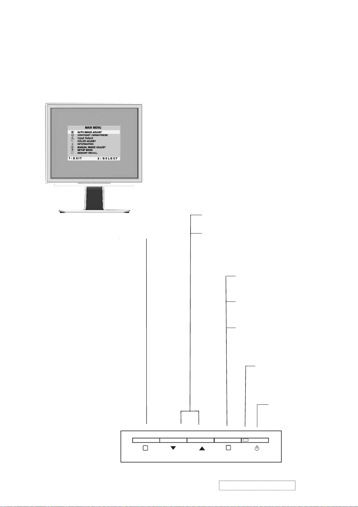
3. Front Panel Function Control Description
Adjusting the Screen Image
Use the buttons on the front control panel to display and adjust the OnView®
controls which display on the screen. The OnView controls are explained at the
top of the next page.
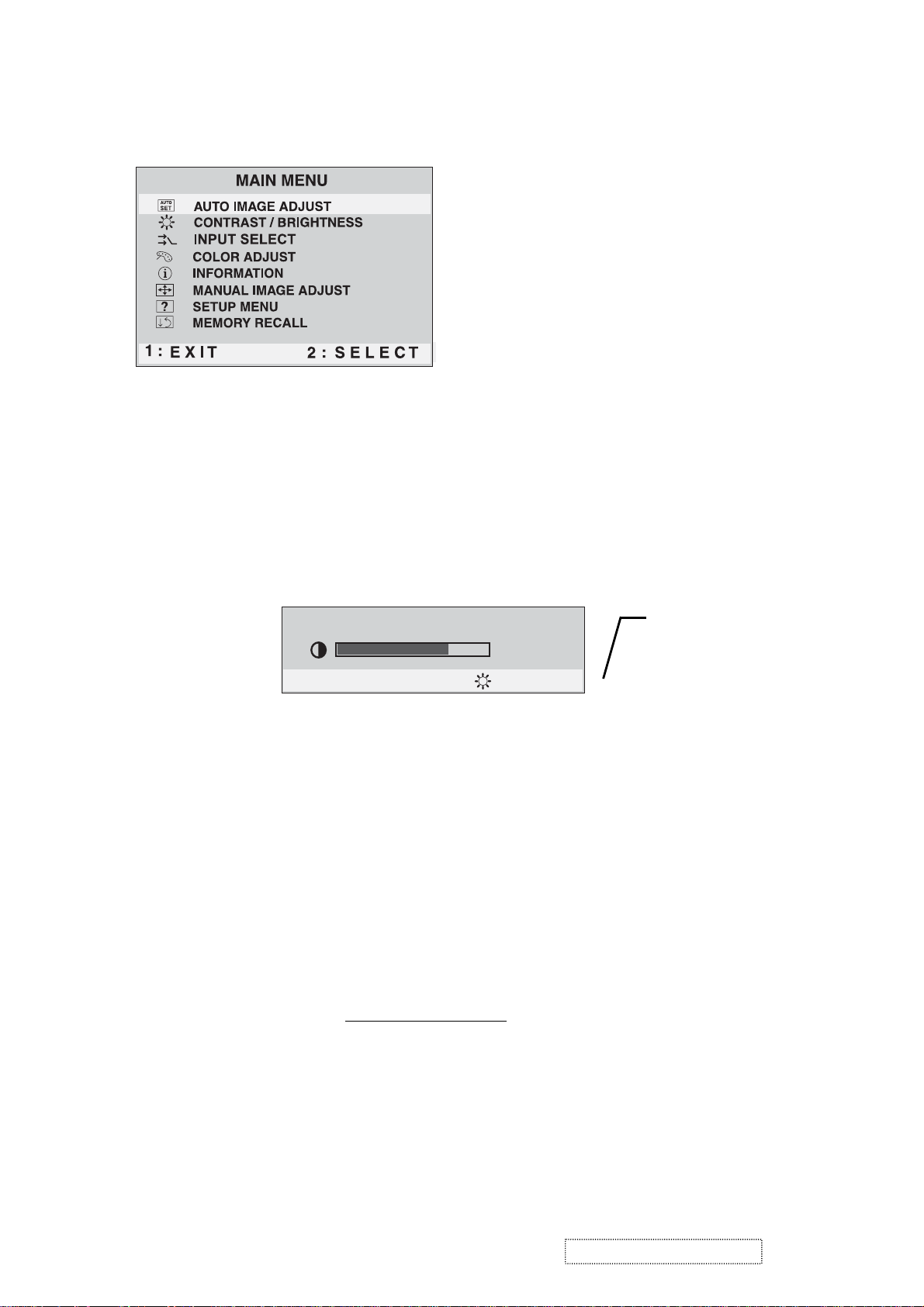
Main Menu
With OnView controls
Front Control Panel
shown below in detail
Displays the Main Menu
or exits the control screen
and saves adjustments
Scrolls through menu options and
adjusts the displayed control.
Also a shortcut to display the
Contrast adjustment control
screen.
Displays the control
screen for the highlighted
control.
Also toggles between two
controls on some
screens.
Also a shortcut to toggle
between analog and
digital connections.
Power light
Green = ON
Orange = Power
Saving
1
ViewSonic Corporation Confidential
11
2
Power
On/Off
-
Do Not Copy VX715
Page 15
Do the following to adjust the screen image:
To display the Main Menu, press button [1].
1
NOTE:
All OnView menus and adjustment screens disappear automatically
after about 30 seconds.
To select a control you want to adjust, press ▲ or ▼ to scroll up or down the
2
Main Menu.
After the control is selected, press button [2]. A control screen like the one
3
shown below appears.
Contrast
1: Exit 2 : Brightness
To adjust the control, press the up ▲ or down ▼ buttons.
4
To save the adjustments and exit the menu, press button [1]
5
The line at the
bottom of the
screen tells you
what you can do
next: Exit or select
the Brightness
control.
.
twice
The following tips may help you optimize your display:
• Adjust your computer's graphic card so that it outputs a video signal 1280 x
1024 @ 60 Hz to the LCD display. (Look for instructions on “changing the
refresh rate” in your graphic card's user guide.)
• If necessary, make small adjustments using H POSITION and V POSITION
until the screen image is completely visible
. (The black border around the
edge of the screen should barely touch the illuminated “active area” of the
LCD display.)
ViewSonic Corporation Confidential
12
-
Do Not Copy VX715
Page 16
Main Menu Controls
Adjust the menu items shown below by using the up ▲ and down ▼ buttons.
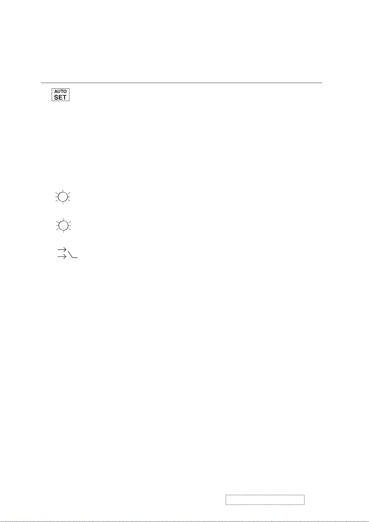
Control Explanation
automatically sizes, centers, and fine tunes
Auto Image Adjust
the video signal to eliminate waviness and distortion.
Press the [2] button to obtain a sharper image.
NOTE:
1. Auto Image Adjust works with most common video cards.
If this function does not work on your LCD display, then
lower the video refresh rate to 60 Hz and set the resolution
to its
2. The Auto Image Adjust and most Manual Image Adjust
pre-set value.
functions are not available for DVI input.
Contrast
adjusts the difference between the image background
(black level) and the foreground (white level).
Brightness
Input Select
adjusts background black level of the screen image.
allows you to toggle between an analog and a
digital signal.
ViewSonic Corporation Confidential
13
-
Do Not Copy VX715
Page 17
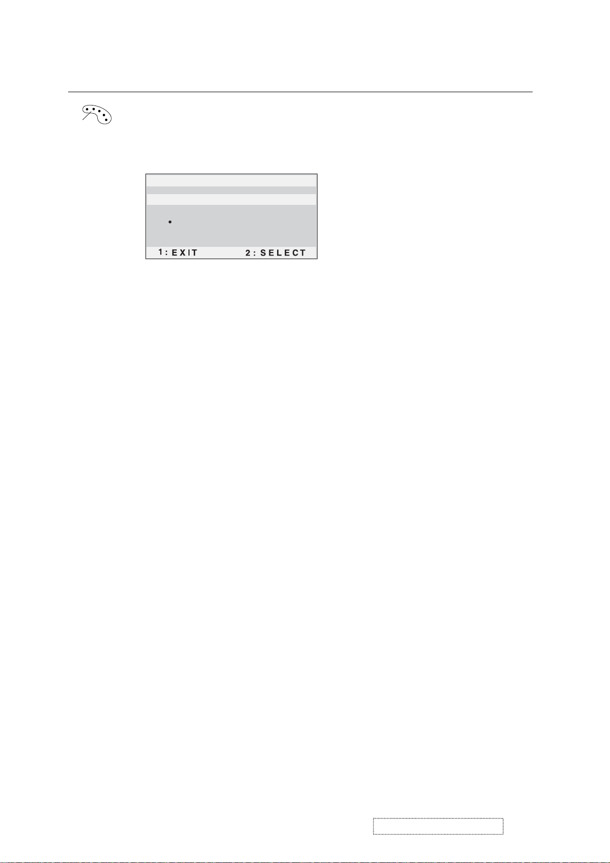
Control Explanation
Color Adjust
color temperatures and
provides several color adjustment modes: preset
RGB
which allows you to adjust red (R),
green (G), and blue (B) separately. The factory setting for this
product is 6500K (6500 Kelvin).
Color Adjust
SRGB
9300K
6500K
5400K
User Color
sRGB
— sRGB is quickly becoming the industry standard for color
management, with support being included in many of the latest
applications. Enabling this setting allows the LCD display to
more accurately display colors the way they were originally
intended. Enabling the sRGB setting will cause the Contrast and
Brightness adjustments to be disabled.
9300K
— Adds blue to the screen image for cooler white (used
in most office settings with fluorescent lighting).
6500K
— Adds red to the screen image for warmer white and
richer red.
5400K
User Color
and blue (B)
1
2
Important
— Adds green to the screen image for a darker color.
— Individual adjustments for red (R), green (G),
.
To select color (R, G or B) press button [2].
To adjust selected color, press ▲ or ▼.
: If you select RECALL from the Main Menu when
the product is set to a Preset Timing Mode, colors return to the
6500K factory preset.
ViewSonic Corporation Confidential
14
-
Do Not Copy VX715
Page 18
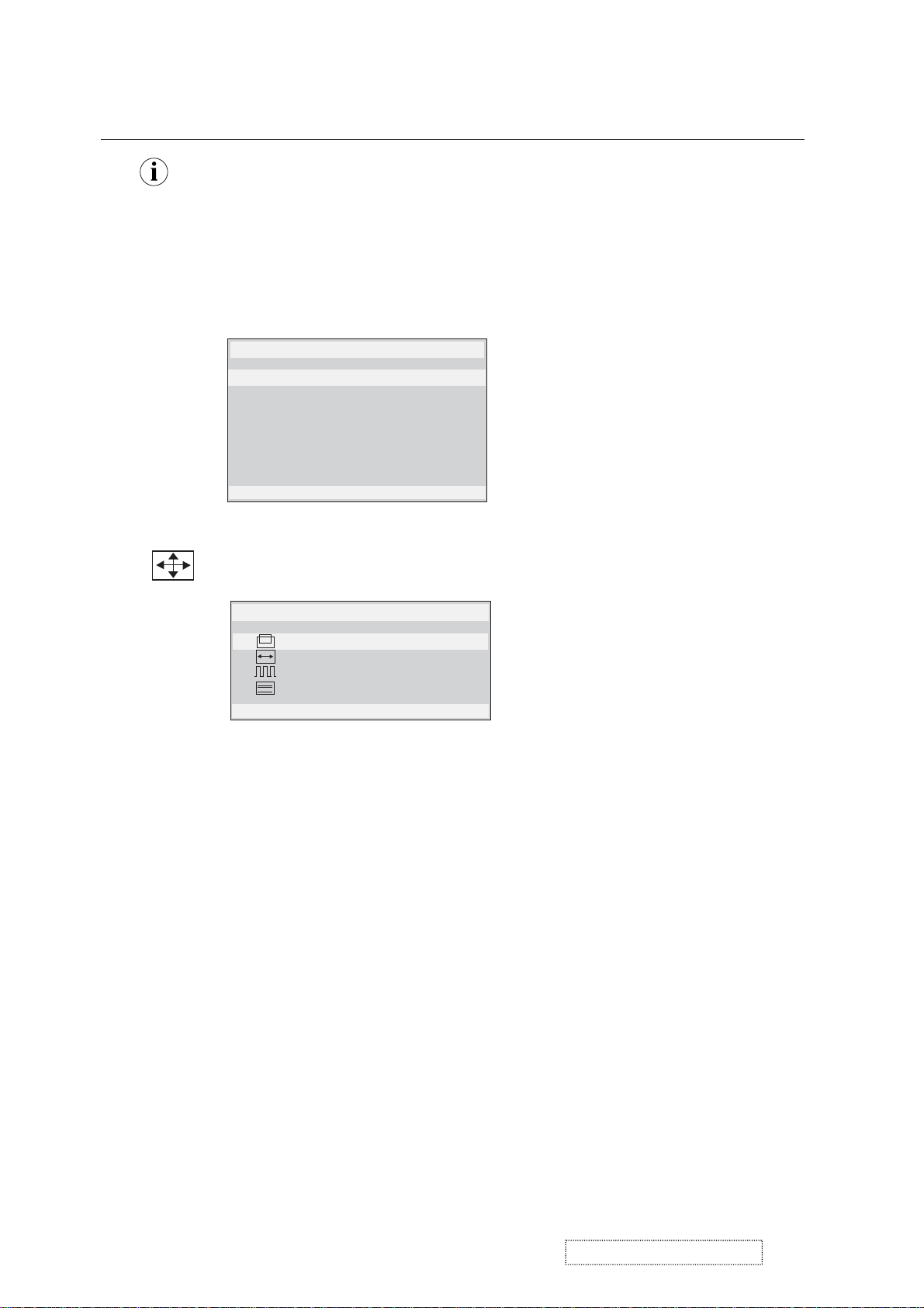
Control Explanation
Information
displays the timing mode (video signal input)
coming from the graphics card in your computer. See your
graphic card’s user guide for instructions on changing the
resolution and refresh rate (vertical frequency).
NOTE:
VESA 1280 x 1024 @ 60 Hz (recommended) means
that the resolution is 1280 x 1024 and the refresh rate is 60
Hertz.
Information
H. Frequency: 31.47 KHz
V. Frequency: 31.47 Hz
Pixel Clock: 24.80 MHz
Resolution: 640 x 480
Model No. :
Serial No. :
1: Exit
Manual Image Adjust
www.viewsonic.com
displays the Manual Image Adjust menu.
Manual Image Adjust
H . / V . Position
H . Size
Fine Tune
Sharpness
1: Exit 2 : Select
The
Manual Image Adjust
Horizontal Position
Vertical Position
Horizontal Size
sharpens focus by aligning the illuminated text and/
Fine Tune
moves the screen image left or right.
moves the screen image up or down.
adjusts the width of the screen image.
or graphic characters.
adjusts the clarity and focus of the screen image.
Sharpness
controls are explained below:
ViewSonic Corporation Confidential
15
-
Do Not Copy VX715
Page 19

Control Explanation
Setup Menu
Language Select
Resolution Notice
OSD Position
OSD Time Out
OSD Background
1: Exit
The
Setup Menu
Language
displays the menu shown below.
Setup Menu
controls are explained below:
allows you to choose the language used in the menus
and control screens.
Resolution Notice
below.
displays the Resolution Notice menu shown
Resolution Notice
OSD Position
advises the optimal resolution to use.
allows you to move the on-screen display menus
and control screens.
sets the length of time an on-screen display
OSD Timeout
screen is displayed. For example, with a “15 second” setting, if
a control is not pushed within 15 seconds, the display screen
disappears.
OSD Background
allows you to turn the On-Screen-Display
background on or off.
Memory Recall
returns adjustments to the original factory
settings if the display is operating in a factory Preset Timing
Mode listed in this user guide.
Exception:
This control does not affect changes made with the
User Color control, Language and Power Lock setting.
ViewSonic Corporation Confidential
16
-
Do Not Copy VX715
Page 20

Short Cut Key
Function key: 5 keys [ 1 ] [▼] [▲] [ 2 ] [ ]
[1] Main Menu
[2] Input toggle (Analog or Digital) or Auto Image Adjust.
[▼] or [▲]
to immediately activate Contrast menu. It should be
change to Brightness OSD by push button [2]
[▼]+ [▲]
recall both of Contrast and Brightness to default
toggle 720x400 and 640x400 mode when input 720x400
[1] + [2]
or 640x400 mode
[1] + [▼] + [▲]
[1] + [▼]
[1] + [▲]
White Balance. (Not shown on user’s guide)
Power Lock
OSD Lock
[2] + [ ] Factory Mode
Remark : All the short cuts function are only available while OSD off
ViewSonic Corporation Confidential
17
-
Do Not Copy VX715
Page 21

4. Circuit Description
4.1 LCD MONITOR DESCRIPTION
The LCD MONITOR contains a Main Board, a Power Board and a Key Board.
The Power Board will provide AC to DC Inverter voltage to drive the backlight of panel and the Main Board.
Monitor Block Diagram
CCFL Drive.
Flat Panel and
CCFL backlight
Power Board
Key Board
AC-IN
100V-240V
Main Board
HOST Computer
RS232 Connector
For white balance
adjustment in factory
mode
Video signal, DDC
ViewSonic Corporation Confidential
18
-
Do Not Copy VX715
Page 22

4.2 POWER BLOCK FUNCTION DESCRIPTION
Buck Converter
Buck Converter
ViewSonic Corporation Confidential
19
-
Do Not Copy VX715
Page 23

4.3 POWER BLOCK FUNCTION
ViewSonic Corporation Confidential
20
-
Do Not Copy VX715
Page 24

S
5. Adjusting Procedure
5.1 ADJUSTMENT CONDITIONS AND PRECAUTION
1. Approximately 30 minutes should be allowed for warm up before proceeding.
2. Adjustments should be undertaken only on those necessary elements since most of them have been carefully
preset at the factory.
3. ESD protection is needed before adjustment.
5.2 MAIN ADJUSTMENTS
NO. FUNCTIONS DESIGNATION
1. White Balance Function Key
2. GEOMETRY Function Key
5.3 ALIGNMENT PROCEDURES
Approximately 30 minutes should be allowed for warm up before proceeding White-Balance adjustment.
1. Adjust of White Balance
1) How to do the Chroma-7120 MEM .Channel setting
A. Reference to chroma 7120 user guide
B. Use “ SC” key and “ NEXT” key to modify xyY value and use “ID” key to modify the TEXT description
Following is the procedure to do white-balance adjust
2) Setting the color temp. You want
A. MEM.CHANNEL9 ( 9300 color):
9300 color temp. parameter is Wx = 0.283 ±0.03;Wy = 0.298 ±0.03 ;
Y = 250 ±20 cd/m
B. MEM.CHANNEL10 ( 6500 color):
2 ,
6500 color temp. parameter is Wx = 0.313±0.03;Wy = 0.329 ±0.03;
Y = 250 ±20 cd/m
2,
C. MEM.CHANNEL 11 ( 5400 color):
5400 color temp. parameter is Wx = 0.335±0.03;Wy = 0.350 ±0.03;
Y = 250 ±20 cd/m2,
3) Into factory mode of VX715
A. First Power off, then press Switch 2 button along with press Power button will activate the factory mode,
then MCU will do AUTO LEVEL automatically. Meanwhile press MENU the OSD screen will located at
LEFT TOP OF PANEL.
4) Bias adjustment :
Set the Contrast
Adjust the Brightness
to 70
to 100.
ViewSonic Corporation Confidential
21
-
Do Not Copy VX715
Page 25

5) Gain adjustment :
Move cursor to “-F-” and press MENU key
A、Adjust 9300 color-temperature
(1)、Switch the Chroma-7120 to RGB-Mode (with press “MODE” button )
(2)、Switch the MEM. channel to Channel 9 ( with up or down arrow on chroma 7120 )
(3)、The LCD-indicator on chroma 7120 will show x = 0.283 ±0.03, y =0.298 ±0.03, Y = 250 ±20 cd/m
(4)、Adjust the RED of color1 on factory window until chroma 7120 indicator reached the value R=100
(5)、Adjust the GREEN of color1 on factory window until chroma 7120 indicator reached the value G=100
(6)、Adjust the BLUE of color1 on factory window until chroma 7120 indicator reached the value B=100
(7)、Repeat above procedure ( item 4,5,6) until chroma 7120 RGB value meet the
tolerance =100±5
B、Adjust 6500 color-temperature
(1)、Switch the chroma-7120 to RGB-Mode (with press “MODE” button )
(2)、Switch the MEM .channel to Channel 10( with up or down arrow on chroma 7120 )
(3)、The LCD-indicator on chroma 7120 will show x = 0.313 ±0.03, y = 0.329 ±0.03, Y = 250 ±20 cd/m
(4)、Adjust the RED of color3 on factory window until chroma 7120 indicator reached the value R=100
(5)、Adjust the GREEN of color3 on factory window until chroma 7120 indicator reached the value G=100
(6)、Adjust the BLUE of color3 on factory window until chroma 7120 indicator reached the value B=100
(7)、Repeat above procedure ( item 4,5,6) until chroma 7120 RGB value meet the
tolerance =100±5
C、Adjust 5400 color-temperature
(1) Switch the chroma-7120 to RGB-Mode (with press “MODE” button )
(2)、Switch the MEM .channel to Channel 11( with up or down arrow on chroma 7120 )
(3)、The LCD-indicator on chroma 7120 will show x = 0.335 ±0.03, y = 0.350 ±0.03, Y = 250 ±20 cd/m
(4)、Adjust the RED of color3 on factory window until chroma 7120 indicator reached the value R=100
(5)、Adjust the GREEN of color3 on factory window until chroma 7120 indicator reached the value G=100
(6)、Adjust the BLUE of color3 on factory window until chroma 7120 indicator reached the value B=100
(7)、Repeat above procedure ( item 4,5,6) until chroma 7120 RGB value meet the
tolerance =100±5
D、Press reset key and Turn the Power-button “off to on” to quit from factory mode.
2. Geometry
1) Set cross-hatch pattern and preset timing as timing table listed.
2) Change to each mode in turn and wait for the monitor finish auto-alignment and save press before change
to next mode.
3) After all of modes are adjusted,exit OSD menu and press PWR OFF to exit factory mode.
2
2
2
ViewSonic Corporation Confidential
22
-
Do Not Copy VX715
Page 26

FIRMWARE UPGRADE PROCEDURE
1. Equipment Needed:
· VX715 Series Monitor
· Signal Cable *2
· RS232 Cable *1
· Fixture of Firmware Upgrade
· Adapter *1 For Fixture
· PC(Personal Computer)
· Firmware Upgrade Program
· One additional Monitor for checking the program execution
ViewSonic Corporation Confidential
23
-
Do Not Copy VX715
Page 27

2. Set Up Procedure:
1) Connector A of Fixture with Chroma by Signal Cable;
(Noted:Connector A may also be disconnected by Signal Cable)
2) Connector B of Fixture with VX715 Monitor by Signal Cable;
3) Connector C of Fixture with PC( Connected F) by RS232 Cable;
4) Connector D of Fixture Adapter;
5) Connector PC to another Monitor;
6) When Adapter Power ON,LED for E will be green;
ViewSonic Corporation Confidential
24
-
Do Not Copy VX715
Page 28

7) Make VX715 Monitor into ISP Mode:
All along press key [?]? [2] of the monitor ,which will be written( the second key
and fourth key count from left to right, as the follow figure), then pull out and insert
the 220V AC plug of power cable to make the monitor entering ‘ISP’ Write mode at
the same time ,until ’ISP’ appeared;
First press the key [?]? [2];Secondly pull out and insert the 220V AC plug to enter ISP
Writer mode.
8) Install ISP Program:
Please install ISP Program according to the following Procedure:
1. Extract ‘ISP30919’ to Portfolio ISP30919;
2. Knocking “ISP30919” “IspWriter” “8051IspWriter”one after another,until
appear ISP Module;
Please refer to the following diagrams.
ViewSonic Corporation Confidential
25
-
Do Not Copy VX715
Page 29

ViewSonic Corporation Confidential
26
-
Do Not Copy VX715
Page 30

3. Firmware Upgrade Procedure:
1) When ISP module appears,Do ‘STEP 1, STEP 2, STEP 3, STEP 4, STEP 5 describing
them folloing:
STEP 1: Select MCU Chip type for W78E65;
STEP 2: Select FIRMWARE that VX715 Monitor applied;After STEP 2,
And select FIRMWARE File Format that’s the same to FIRMWARE.
STEP 3: Select COM1,refer to the above F;
STEP 4: Knocking ‘ConNect’,it makes PC and VX715 Monitor connected;
STEP 5: When STEP 4 is OK,do STEP 5;
ViewSonic Corporation Confidential
27
-
Do Not Copy VX715
Page 31

2) After STEP 5, Firmware is being programmed, referring to STEP 6.When
Program is OK, knocking OK, referring to STEP 7.The Firmware Upgrading is successful.
ViewSonic Corporation Confidential
28
-
Do Not Copy VX715
Page 32

3) Exit ISP mode,Refer to Chapter 5.3 for ALIGNMENT PROCEDURES to do ‘White
Balance’
4) At last,do ‘all mode reset’.
ViewSonic Corporation Confidential
29
-
Do Not Copy VX715
Page 33

6. Trouble Shooting Flow Chart
ViewSonic Corporation Confidential
30
-
Do Not Copy VX715
Page 34

7. Recommended Spare Parts List
VX715 Recommended Spare Parts List
VX715-1 RSPL Rev 1b
Item Revision History ViewSonic P/N Ref.P/N Description Location Q'ty
1-1 M-MS-0808-9497 15L80121 MAIN FRAME MAIN FRAME 1
1-2 Added 2nd Source 08/03/02 M-MS-0808-9870 15L80123 MAIN FRAME MAIN FRAME 1
2 C-BC-0302-0599 23L31787092A VSC17-LCD BACKCOVER BACKCOVER 1
3 C-FP-0301-9936 23L31787093A VSC17-LCD FRONT LEFT FRONT LEFT 1
4 M-MS-0808-9490 23L31787094A VSC17-LCD FRONT LOGO FRONT LOGO 1
5 M-CV-0830-2548 34L1326KRB STAND-R-COVER COVER 1
6 M-CV-0830-2549 34L1327KSB BUCKET-R-COVER COVER 1
7 M-LB-0813-0995 40L152509 RECYCLE LABEL RECYCLE LABEL 0
8 M-LB-0813-0996 40L152512 RECYCLE LABEL RECYCLE LABEL 0
9 M-LB-0813-0997 40L1907091B ID LABEL ID LABEL 1
10 M-LB-0813-0998 40L4597091B CARTON LABEL CARTON LABEL 1
11 M-LB-0813-0999 40L4597092B S/N LABEL S/N LABEL 1
12 M-LB-0813-1000 40L4597094A H/V WARNING LABEL WARNING LABEL 1
13 M-LB-0813-1001 40L4597095A HI-POT LABEL FOR 17- HI-POT LABEL 1
14 M-LB-0813-1002 40L58170918D PALLET LABEL PALLET LABEL 0.25
15 P-BX-0601-0973 44L37347091A CARTON CARTON 1
16 M-MS-0808-9498 44L600210A PAPER PLATE PAPER PLATE 0.025
17 M-MS-0808-9491 45L7628V3 PE BAG FOR MANUAL PE BAG 1
18-1 M-MS-0808-9499 45L77501 BARCODE RIBBON BARCODE RIBBON 3
18-2 Added 2nd Source 08/03/02 M-MS-0808-9871 45L773 BARCODE RIBBON BARCODE RIBBON 3
19 M-MS-0808-9492 45L88607 PE BAG FOR MONITOR PE BAG 1
20 M-CV-0830-2550 45L88609B EPE COVER EPE COVER 1
21 M-MS-0808-9493 45L8861828 OUT PE BAG PE BAG 1
22 M-MS-0808-9494 50L6002 HANDLE1 HANDLE 1
23 M-MS-0808-9495 50L6003 HANDLE2 HANDLE 1
24 M-MS-0808-9500 52L1185 MIDDLE TAPE FOR CART MIDDLE TAPE 0
25 M-MS-0808-9501 52L1186 SMALL TAPE SMALL TAPE 8
26 M-MS-0808-9502 52L60201 PROTECT FILM PROTECT FILM 0
27 M-MS-0808-9568 52L602511655 MYLAR MYLAR 1
28 M-MS-0808-9569 52L602511675 MYLAR MYLAR 1
29-1 A-CD-VX715 70L17007091A CD MANUAL CD MANUAL 1
29-2 Added 2nd Source 08/03/02 M-MS-0808-9871 70L17007092A CD MANUAL CD MANUAL 1
30 M-MS-0808-9570 85L6621 SHIELD SHIELD 1
31 A-VC-0101-0379 89L1738LAA5 D-SUB SIGNAL CABLE SIGNAL CABLE 1
32 M-MS-0808-9503 95L80141212 POWER LINE 16P-12P POWER LINE 1
33-1 M-MS-0808-9504 95L801830523 HARNESS HARNESS 1
33-2 Added 2nd Source 08/03/02 M-MS-0808-9872 95L80183033 HARNESS HARNESS 1
34-1 M-LCD-0826-0226 750LLC70A02 CPT 17" LCD Panel(A02) LCD Panel 1
34-2 Added 2nd Source 08/03/02 M-LCD-0826-0249 750LLK70131 HYDIS17"13-100 PAND TI IC(110) LCD Panel 1
35 M-LB-0813-1003 40L4576241B CPU LABEL CPU LABEL 1
36-1 M-LB-0813-1004 40L45762412A CBPC LABEL CBPC LABEL 1
36-2 Added 2nd Source 08/03/02 M-LB-0830-0710 40L45760819A CBPC LABEL CBPC LABEL 1
37-1 B-MB-0201-2731 CBPC780KCQVW PCB PCB 1
37-2 Added 2nd Source 08/03/02 B-MB-0201-2775 715L12031B MAIN BOARD PCB PCB 1
38 B-KB-0207-0050 KEPC780KC9 KEY BOARD KEY BOARD 1
39-1 B-SB-0221-0635 PWPC1742CPV1 POWER BOARD POWER BOARD 1
39-2 Added 2nd Source 08/03/02 B-SB-0221-0691 715L1075BV1 POWER BOARD PCB PCB 1
40 Added 04/12/04 M-MS-0808-9571 41L78007091A QUICK START GUIDE QSG 1
41 Added 04/12/04 P-FM-0602-0882 44L37341 EPS ( L ) EPS ( L ) 1
42 Added 04/12/04 P-FM-0602-0883 44L37342 EPS ( R ) EPS ( R ) 1
43 Added 04/12/04 M-MS-0808-9492 45L88607 PE BAG PE BAG 1
44 Added 04/12/04 C-FP-0301-1003 34L1320KSB Front panel Front panel 1
45 Added 04/12/04 C-BC-0302-0604 34L1322KSB back cover back cover 1
VX715-1 M Model Rev 1a
Item ViewSonic P/N Ref. P/N Description Location Q'ty
1 A-PC-0106-0226 89L402A18NYH POWER CORD POWER CORD 1
VX715-1 E Model Rev 1a
Item ViewSonic P/N Ref. P/N Description Location Q'ty
1 A-PC-0106-0226 89L404A18NYH POWER CORD POWER CORD 1
VX715-1 G Model RSPL Rev 1b
Item ViewSonic P/N Ref. P/N Description Location Q'ty
1 A-PC-0106-0226 89L414A18NYH POWER CORD POWER CORD 1
ViewSonic Corporation Confidential
31
-
Do Not Copy VX715
Page 35

ViewSonic P/N
Reference P/N
ViewSonic P/N
Reference P/N
VX715-1 RSPL
Rev 1b
Revision History
Item
Description of Change
From To or Newly add Items
1-2 N/A
18-2 N/A
29-2 N/A
33-2 N/A
34-2 N/A
36-2 N/A
37-2 N/A N/A B-MB-0201-2775 715L12031B 08/03/04: Added 2nd source.
39-2 N/A N/A B-SB-0221-0691 715L1075BV1 08/03/04: Added 2nd source.
40 N/A N/A M-MS-0808-9571 41L78007091A 04/12/04: Added to RSPL.
41 N/A N/A P-FM-0602-0882 44L37341 04/12/04: Added to RSPL.
42 N/A N/A P-FM-0602-0883 44L37342 04/12/04: Added to RSPL.
43 N/A N/A M-MS-0808-9492 45L88607 04/12/04: Added to RSPL.
44 N/A N/A C-FP-0301-1003 34L1320KSB 04/12/04: Added to RSPL.
45 N/A N/A C-BC-0302-0604 34L1322KSB 04/12/04: Added to RSPL.
N/A
N/A
N/A
N/A
N/A
N/A
M-MS-0808-9870
M-MS-0808-9871
M-MS-0808-9871
M-MS-0808-9872 95L80183033 08/03/04: Added 2nd source.
M-LCD-0826-0249 750LLK70131 08/03/04: Added 2nd source.
M-LB-0830-0710 40L45760819A 08/03/04: Added 2nd source.
15L80123
45L773
70L17007092A
08/03/04: Added 2nd source.
08/03/04: Added 2nd source.
08/03/04: Added 2nd source.
ViewSonic Corporation Confidential
32
-
Do Not Copy VX715
Page 36

Item
ViewSonic P/N
ReferenceP/N
Description
Location
Q'ty
Unit
VX715-1 BOM Rev 1b (Hydis panel)
1 #N/A CBPC780KKQVW CONVERSION BOARD CONVERSION BOARD 1 PCS
2 B-KB-0207-0050 KEPC780KC9 KEY BOARD KEY BOARD 1 PCS
3 #N/A PWPC1742HDV1 POWER BOARD POWER BOARD 1 PCS
4 #N/A 7L1LV82 WOODEN PALLET WOODEN PALLET 0.025 PCS
5 M-MS-0808-9870 15L80123 MSIN GTSMR GTSMR 1 PCS
6 #N/A 15L80181 FRAME-BKT FRAME 1 PCS
7 #N/A 19L60141 CLIP CLIP 0.2 PCS
8 #N/A 23L31787092A VSC17-LCD BACKCOVER BACKCOVER 1 PCS
9 C-FP-0301-9936 23L31787093A VSC17-LCD FRONT LEFT FRONT LEFT 1 PCS
10 M-MS-0808-9490 23L31787094A VSC17-LCD FRONT LOGO FRONT LOGO 1 PCS
11 M-CV-0830-2548 34L1326KRB STAND-R-COVER COVER 1 PCS
12 M-CV-0830-2549 34L1327KSB BUCKET-R-COVER COVER 1 PCS
13 M-LB-0813-0995 40L152509 RECYCLE LABEL LABEL 0 PCS
14 M-LB-0813-0996 40L152512 RECYCLE LABEL LABEL 0 PCS
15 #N/A 40L1907095A ID LABEL LABEL 1 PCS
16 M-LB-0830-0710 40L45760819A ID LABEL LABEL 1 PCS
17 M-LB-0813-0998 40L4597091B CARTON LABEL LABEL 1 PCS
18 M-LB-0813-0999 40L4597092B S/N LABEL LABEL 1 PCS
19 M-LB-0813-1000 40L4597094A H/V WARNING LABEL LABEL 1 PCS
20 M-LB-0813-1001 40L4597095A HI-POT LABEL FOR 17-L LABEL 1 PCS
21 #N/A 40L58126704 FOR CARTON/PALL CARTON 0.01 PCS
22 M-LB-0813-1002 40L58170918D PALLET LABEL LABEL 0.25 PCS
23 #N/A 41L68508A MANUAL MANUAL 0.1 PCS
24 #N/A 41L78007093A QSG QSG 1 PCS
25 P-FM-0602-0882 44L37341 EPS(L) EPS 1 PCS
26 P-FM-0602-0883 44L37342 EPS(R) EPS 1 PCS
27 P-BX-0601-0973 44L37347091A CARTON CARTON 1 PCS
28 M-MS-0808-9498 44L600210A PAPER PLATE PLATE 0.025 PCS
29 #N/A 44L60027092A PAPER PLATE PLATE 0.025 PCS
30 #N/A 44L9003210 CORNER PAPER PAPER 0.1 PCS
31 M-MS-0808-9491 45L7628V3 PE BAG FOR MANUAL PE BAG 1 PCS
32 M-MS-0808-9871 45L773 PACKING VELUM VELUM 73 CM
33 M-MS-0808-9492 45L88607 PE BAG FOR MONITOR PE BAG 1 PCS
34 #N/A 45L886094 EPE COVER COVER 1 PCS
35 M-CV-0830-2550 45L88609B EPE COVER COVER 1 PCS
36 #N/A 50L6001W PACKING STRIP STRIP 74 CM
37 M-MS-0808-9494 50L6002 HANDLE1 HANDLE 1 PCS
38 M-MS-0808-9495 50L6003 HANDLE2 HANDLE 1 PCS
39 M-MS-0808-9500 52L1185 MIDDLE TAPE FOR CARTO MIDDLE TAPE 60 CM
40 #N/A 52L118524 VSC TAPE TAPE 65 CM
41 M-MS-0808-9501 52L1186 SMALL TAPE TAPE 8 CM
42 #N/A 52L1213607 ALUMINUM FOIL ALUMINUM FOIL 1 PCS
43 M-MS-0808-9502 52L60201 PROTECT FILM FILM 1 PCS
44 M-MS-0808-9502 52L60201 PROTECT FILM FILM 0 PCS
45 #N/A 52L602220 SMALL TAPE TAPE 0 MM
46 M-MS-0808-9568 52L602511655 MYLAR MYLAR 1 PCS
47 M-MS-0808-9569 52L602511675 MYLAR MYLAR 1 PCS
48 #N/A 70L17007092A CD MANUAL MANUAL 1 PCS
49 #N/A 85L583509 FROTH COTTON COTTON 2 PCS
50 M-MS-0808-9570 85L6621 SHIELD SHIELD 1 PCS
51 A-VC-0101-0379 89L1738LAA5 D-SUB SIGNAL CABLE SIGNAL CABLE 1 PCS
52 A-PC-0106-0226 89L402A18NYH POWER CORD CORD 1 PCS
53 M-MS-0808-9503 95L80141212 POWER LINE 16P-12P POWER LINE 1 PCS
54 M-MS-0808-9872 95L80183033 HARNESS 110MM 24P-30P HARNESS 1 PCS
55 #N/A M1L1406120 SCREW M4X6 SCREW 8 PCS
56 #N/A M1L3304128 SCREW M3X4 SCREW 2 PCS
57 #N/A M1L3306128 SCREW SCREW 4 PCS
58 #N/A M1L10306128 SCREW SCREW 2 PCS
59 #N/A M1L11406120 SCREW SCREW 1 PCS
60 #N/A M1L17306128 SCREW M3x6 SCREW 8 PCS
61 #N/A M1L2130447 SCREW SCREW 4 PCS
62 #N/A 705L782KB3476 BACK COVER ASS'Y BACK COVER 1 PCS
63 M-LCD-0826-0249 750LLK70131 HYDIS17"13-100 PAND T Hydis PENAL 1 PCS
64 #N/A AIC780KKQVW MAIN BOARD MAIN BOARD 1 PCS
65 #N/A 33L801724AH PIN HEADER 24P 2.0mm CN503 1 PCS
ViewSonic Corporation Confidential
-
Do Not Copy VX715
33
Page 37

Item ViewSonic P/N ReferenceP/N Description Location Q'ty Unit
66 #N/A 33L802712 WAFER 2*6P 2.0MM R/A CN201 1 PCS
67 #N/A 33L802716 WAFER 16PIN 2.0mm DIP CN602 1 PCS
68 M-LB-0813-1003 40L4576241B CPU LABEL LABEL 1 PCS
69 #N/A 40L45762412B CBPC LABEL LABEL 1 PCS
70 #N/A 44L3231508512 ELECTRIC FROTH COTTON COTTON 1 PCS
71 #N/A 44L3231508513 ELECTRIC FROTH COTTON COTTON 1 PCS
72 #N/A 56L1125137KV1 W78E65P-40 BY WINBORD U601 1 PCS
73 #N/A 67L215B2214H LOW ESR 220UF 25V 8*1 C202 1 PCS
74 #N/A 67L215B2214H LOW ESR 220UF 25V 8*1 C204 1 PCS
75 #N/A 67L309V1003 10uf =_20% 16v C208 1 PCS
76 #N/A 67L309V1003 10uf =_20% 16v C405 1 PCS
77 #N/A 67L309V1003 10uf =_20% 16v C414 1 PCS
78 #N/A 67L309V1003 10uf =_20% 16v C419 1 PCS
79 #N/A 67L309V1003 10uf =_20% 16v C422 1 PCS
80 #N/A 67L309V1003 10uf =_20% 16v C424 1 PCS
81 #N/A 67L309V1003 10uf =_20% 16v C427 1 PCS
82 #N/A 67L309V1003 10uf =_20% 16v C603 1 PCS
83 #N/A 67L309V2203 22UF +-20% 16V C509 1 PCS
84 #N/A 67L309V4703 47UF 16V 85C C211 1 PCS
85 #N/A 67L309V4703 47UF 16V 85C C215 1 PCS
86 #N/A 88L35315FHS D-SUB 15PIN FEMALE CN301 1 PCS
87 #N/A 88L35424FHS DVID CONN 24P CN302 1 PCS
88 #N/A 93L2253 CRYSTAL 14.318MHzHC-4 X401 1 PCS
89 E-X-0415-0131 93L2255H 20MHZ X601 1 PCS
90 #N/A 56L56260 MST8131B PQFP-128 U401 1 PCS
91 #N/A 56L56325 AIC1084-33CE T0-252 U202 1 PCS
92 E-IC-0401-2676 56L5855 RT9164-25CG U201 0 PCS
93 #N/A 56L5855A AP1117E25A U201 1 PCS
94 #N/A 56L113334 M24C02-WMN6T SMT U301 1 PCS
95 #N/A 56L113334 M24C02-WMN6T SMT U302 1 PCS
96 #N/A 56L113356 M24C16-WMN6T/W SO-8 U602 1 PCS
97 #N/A 57L4174 PMBS3904/PHILIPS-SMT( Q201 1 PCS
98 #N/A 57L4174 PMBS3904/PHILIPS-SMT( Q202 1 PCS
99 #N/A 57L4174 PMBS3904/PHILIPS-SMT( Q204 1 PCS
100 #N/A 57L4176 PMBS3906/PHILIPS-SMT( Q601 1 PCS
101 #N/A 57L4176 PMBS3906/PHILIPS-SMT( Q602 1 PCS
102 #N/A 57L7631 A03401 SOT23 BY AOS(A Q203 1 PCS
103 #N/A 61L1251038 CHIP AR 8P4R 10KOHM + RN601 1 PCS
104 #N/A 61L1251038 CHIP AR 8P4R 10KOHM + RN602 1 PCS
105 #N/A 61L0603000 CHIPR 0OHM +-5% 1/10W R209 1 PCS
106 #N/A 61L0603000 CHIPR 0OHM +-5% 1/10W R502 1 PCS
107 #N/A 61L0603101 CHIPR 100 OHM +-5% 1/ R305 1 PCS
108 #N/A 61L0603101 CHIPR 100 OHM +-5% 1/ R306 1 PCS
109 #N/A 61L0603101 CHIPR 100 OHM +-5% 1/ R307 1 PCS
110 #N/A 61L0603101 CHIPR 100 OHM +-5% 1/ R309 1 PCS
111 #N/A 61L0603101 CHIPR 100 OHM +-5% 1/ R312 1 PCS
112 #N/A 61L0603101 CHIPR 100 OHM +-5% 1/ R315 1 PCS
113 #N/A 61L0603101 CHIPR 100 OHM +-5% 1/ R316 1 PCS
114 #N/A 61L0603101 CHIPR 100 OHM +-5% 1/ R319 1 PCS
115 #N/A 61L0603101 CHIPR 100 OHM +-5% 1/ R320 1 PCS
116 #N/A 61L0603101 CHIPR 100 OHM +-5% 1/ R321 1 PCS
117 #N/A 61L0603101 CHIPR 100 OHM +-5% 1/ R322 1 PCS
118 #N/A 61L0603101 CHIPR 100 OHM +-5% 1/ R608 1 PCS
119 #N/A 61L0603101 CHIPR 100 OHM +-5% 1/ R609 1 PCS
120 #N/A 61L0603101 CHIPR 100 OHM +-5% 1/ R610 1 PCS
121 #N/A 61L0603101 CHIPR 100 OHM +-5% 1/ R611 1 PCS
122 #N/A 61L0603101 CHIPR 100 OHM +-5% 1/ R620 1 PCS
123 #N/A 61L0603101 CHIPR 100 OHM +-5% 1/ R621 1 PCS
124 #N/A 61L0603101 CHIPR 100 OHM +-5% 1/ R622 1 PCS
125 #N/A 61L0603101 CHIPR 100 OHM +-5% 1/ R623 1 PCS
126 #N/A 61L0603101 CHIPR 100 OHM +-5% 1/ R624 1 PCS
127 #N/A 61L0603102 CHIPR 1K OHM +-5% 1/1 R203 1 PCS
128 #N/A 61L0603102 CHIPR 1K OHM +-5% 1/1 R310 1 PCS
129 #N/A 61L0603102 CHIPR 1K OHM +-5% 1/1 R311 1 PCS
130 #N/A 61L0603103 CHIPR 10K OHM +-5% 1/ R202 1 PCS
131 #N/A 61L0603103 CHIPR 10K OHM +-5% 1/ R204 1 PCS
132 #N/A 61L0603103 CHIPR 10K OHM +-5% 1/ R206 1 PCS
133 #N/A 61L0603103 CHIPR 10K OHM +-5% 1/ R208 1 PCS
ViewSonic Corporation Confidential
34
-
Do Not Copy VX715
Page 38

Item ViewSonic P/N ReferenceP/N Description Location Q'ty Unit
134 #N/A 61L0603103 CHIPR 10K OHM +-5% 1/ R211 1 PCS
135 #N/A 61L0603103 CHIPR 10K OHM +-5% 1/ R308 1 PCS
136 #N/A 61L0603103 CHIPR 10K OHM +-5% 1/ R314 1 PCS
137 #N/A 61L0603103 CHIPR 10K OHM +-5% 1/ R317 1 PCS
138 #N/A 61L0603103 CHIPR 10K OHM +-5% 1/ R318 1 PCS
139 #N/A 61L0603103 CHIPR 10K OHM +-5% 1/ R323 1 PCS
140 #N/A 61L0603103 CHIPR 10K OHM +-5% 1/ R324 1 PCS
141 #N/A 61L0603103 CHIPR 10K OHM +-5% 1/ R404 1 PCS
142 #N/A 61L0603103 CHIPR 10K OHM +-5% 1/ R405 1 PCS
143 #N/A 61L0603103 CHIPR 10K OHM +-5% 1/ R406 1 PCS
144 #N/A 61L0603103 CHIPR 10K OHM +-5% 1/ R407 1 PCS
145 #N/A 61L0603103 CHIPR 10K OHM +-5% 1/ R601 1 PCS
146 #N/A 61L0603103 CHIPR 10K OHM +-5% 1/ R602 1 PCS
147 #N/A 61L0603103 CHIPR 10K OHM +-5% 1/ R603 1 PCS
148 #N/A 61L0603103 CHIPR 10K OHM +-5% 1/ R604 1 PCS
149 #N/A 61L0603103 CHIPR 10K OHM +-5% 1/ R605 1 PCS
150 #N/A 61L0603103 CHIPR 10K OHM +-5% 1/ R606 1 PCS
151 #N/A 61L0603103 CHIPR 10K OHM +-5% 1/ R607 1 PCS
152 #N/A 61L0603103 CHIPR 10K OHM +-5% 1/ R613 1 PCS
153 #N/A 61L0603220 CHIPR 22 OHM+-5% 1/10 FB301 1 PCS
154 #N/A 61L0603220 CHIPR 22 OHM+-5% 1/10 FB302 1 PCS
155 #N/A 61L0603220 CHIPR 22 OHM+-5% 1/10 FB303 1 PCS
156 #N/A 61L0603222 CHIPR 2.2K OHM+-5% 1/ R313 1 PCS
157 #N/A 61L06033900F CHIP 390 OHM 1/10W 1% R403 1 PCS
158 #N/A 61L0603471 CHIPR 470 OHM+-5% 1/1 R304 1 PCS
159 #N/A 61L0603471 CHIPR 470 OHM+-5% 1/1 R617 1 PCS
160 #N/A 61L0603471 CHIPR 470 OHM+-5% 1/1 R618 1 PCS
161 #N/A 61L0603472 CHIPR 4.7K OHM +-5% 1 R201 1 PCS
162 #N/A 61L0603472 CHIPR 4.7K OHM +-5% 1 R205 1 PCS
163 #N/A 61L0603472 CHIPR 4.7K OHM +-5% 1 R207 1 PCS
164 #N/A 61L0603472 CHIPR 4.7K OHM +-5% 1 R212 1 PCS
165 #N/A 61L0603472 CHIPR 4.7K OHM +-5% 1 R402 1 PCS
166 #N/A 61L0603472 CHIPR 4.7K OHM +-5% 1 R616 1 PCS
167 #N/A 61L0603472 CHIPR 4.7K OHM +-5% 1 R619 1 PCS
168 #N/A 61L0603750 CHIPR 75 OHM+-5% 1/10 R325 1 PCS
169 #N/A 61L0603750 CHIPR 75 OHM+-5% 1/10 R326 1 PCS
170 #N/A 61L0603750 CHIPR 75 OHM+-5% 1/10 R327 1 PCS
171 #N/A 65L060310232 1000PF +-10% 50V X7R C307 1 PCS
172 #N/A 65L060310232 1000PF +-10% 50V X7R C606 1 PCS
173 #N/A 65L060310232 1000PF +-10% 50V X7R C607 1 PCS
174 #N/A 65L060310232 1000PF +-10% 50V X7R C608 1 PCS
175 #N/A 65L060310232 1000PF +-10% 50V X7R C609 1 PCS
176 #N/A 65L060310232 1000PF +-10% 50V X7R C610 1 PCS
177 #N/A 65L060310432 CHIP 0.1UF 50V X7R C201 1 PCS
178 #N/A 65L060310432 CHIP 0.1UF 50V X7R C203 1 PCS
179 #N/A 65L060310432 CHIP 0.1UF 50V X7R C205 1 PCS
180 #N/A 65L060310432 CHIP 0.1UF 50V X7R C207 1 PCS
181 #N/A 65L060310432 CHIP 0.1UF 50V X7R C210 1 PCS
182 #N/A 65L060310432 CHIP 0.1UF 50V X7R C212 1 PCS
183 #N/A 65L060310432 CHIP 0.1UF 50V X7R C214 1 PCS
184 #N/A 65L060310432 CHIP 0.1UF 50V X7R C216 1 PCS
185 #N/A 65L060310432 CHIP 0.1UF 50V X7R C313 1 PCS
186 #N/A 65L060310432 CHIP 0.1UF 50V X7R C314 1 PCS
187 #N/A 65L060310432 CHIP 0.1UF 50V X7R C315 1 PCS
188 #N/A 65L060310432 CHIP 0.1UF 50V X7R C401 1 PCS
189 #N/A 65L060310432 CHIP 0.1UF 50V X7R C404 1 PCS
190 #N/A 65L060310432 CHIP 0.1UF 50V X7R C406 1 PCS
191 #N/A 65L060310432 CHIP 0.1UF 50V X7R C407 1 PCS
192 #N/A 65L060310432 CHIP 0.1UF 50V X7R C408 1 PCS
193 #N/A 65L060310432 CHIP 0.1UF 50V X7R C409 1 PCS
194 #N/A 65L060310432 CHIP 0.1UF 50V X7R C410 1 PCS
195 #N/A 65L060310432 CHIP 0.1UF 50V X7R C411 1 PCS
196 #N/A 65L060310432 CHIP 0.1UF 50V X7R C412 1 PCS
197 #N/A 65L060310432 CHIP 0.1UF 50V X7R C413 1 PCS
198 #N/A 65L060310432 CHIP 0.1UF 50V X7R C415 1 PCS
199 #N/A 65L060310432 CHIP 0.1UF 50V X7R C416 1 PCS
200 #N/A 65L060310432 CHIP 0.1UF 50V X7R C417 1 PCS
201 #N/A 65L060310432 CHIP 0.1UF 50V X7R C418 1 PCS
ViewSonic Corporation Confidential
35
-
Do Not Copy VX715
Page 39

Item ViewSonic P/N ReferenceP/N Description Location Q'ty Unit
202 #N/A 65L060310432 CHIP 0.1UF 50V X7R C420 1 PCS
203 #N/A 65L060310432 CHIP 0.1UF 50V X7R C421 1 PCS
204 #N/A 65L060310432 CHIP 0.1UF 50V X7R C423 1 PCS
205 #N/A 65L060310432 CHIP 0.1UF 50V X7R C425 1 PCS
206 #N/A 65L060310432 CHIP 0.1UF 50V X7R C426 1 PCS
207 #N/A 65L060310432 CHIP 0.1UF 50V X7R C428 1 PCS
208 #N/A 65L060310432 CHIP 0.1UF 50V X7R C510 1 PCS
209 #N/A 65L060310432 CHIP 0.1UF 50V X7R C511 1 PCS
210 #N/A 65L060310432 CHIP 0.1UF 50V X7R C601 1 PCS
211 #N/A 65L060310432 CHIP 0.1UF 50V X7R C605 1 PCS
212 #N/A 65L060322031 CHIP 22PF 50V NPO C402 1 PCS
213 #N/A 65L060322031 CHIP 22PF 50V NPO C403 1 PCS
214 #N/A 65L060322031 CHIP 22PF 50V NPO C602 1 PCS
215 #N/A 65L060322031 CHIP 22PF 50V NPO C604 1 PCS
216 #N/A 65L060322131 CAP:CER 220PF 5% 50V C312 1 PCS
217 #N/A 65L060333031 33PF+-5% 50V NPO C311 1 PCS
218 #N/A 65L060347332 CHIP 0.047UF 50V X7R C304 1 PCS
219 #N/A 65L060347332 CHIP 0.047UF 50V X7R C305 1 PCS
220 #N/A 65L060347332 CHIP 0.047UF 50V X7R C306 1 PCS
221 #N/A 65L060347332 CHIP 0.047UF 50V X7R C308 1 PCS
222 #N/A 65L060347332 CHIP 0.047UF 50V X7R C309 1 PCS
223 #N/A 65L060347332 CHIP 0.047UF 50V X7R C310 1 PCS
224 #N/A 65L080510522 CHIP 1UF 25V X7R 0805 C206 1 PCS
225 #N/A 71L56G151A TB160808G151 FB304 1 PCS
226 #N/A 71L56Z601 CHIP BEAD 600 OHM 080 FB201 1 PCS
227 #N/A 71L56Z601 CHIP BEAD 600 OHM 080 FB401 1 PCS
228 #N/A 71L56Z601 CHIP BEAD 600 OHM 080 FB402 1 PCS
229 #N/A 71L56Z601 CHIP BEAD 600 OHM 080 FB403 1 PCS
230 #N/A 71L56Z601 CHIP BEAD 600 OHM 080 FB404 1 PCS
231 #N/A 71L56Z601 CHIP BEAD 600 OHM 080 FB405 1 PCS
232 #N/A 71L56Z601 CHIP BEAD 600 OHM 080 FB406 1 PCS
233 #N/A 71L59C121B FCM1608C-121T03 SMD R301 1 PCS
234 #N/A 71L59C121B FCM1608C-121T03 SMD R302 1 PCS
235 #N/A 71L59C121B FCM1608C-121T03 SMD R303 1 PCS
236 #N/A 87L20244 PLCC SMT CONN PD41C-4 U601 1 PCS
237 #N/A 93L39147 TZMC5V6-GS08 D314 1 PCS
238 #N/A 93L39147 TZMC5V6-GS08 D315 1 PCS
239 #N/A 93L39147 TZMC5V6-GS08 D316 1 PCS
240 #N/A 93L39147 TZMC5V6-GS08 D317 1 PCS
241 #N/A 93L39147 TZMC5V6-GS08 D318 1 PCS
242 #N/A 93L39147 TZMC5V6-GS08 D319 1 PCS
243 #N/A 93L39147 TZMC5V6-GS08 D320 1 PCS
244 #N/A 93L39147 TZMC5V6-GS08 D321 1 PCS
245 #N/A 93L60230 BAT54C(L43) D304 1 PCS
246 #N/A 93L60230 BAT54C(L43) D305 1 PCS
247 #N/A 93L6432V LL4148-GS08 D601 1 PCS
248 #N/A 93L6433P BAV99 D301 1 PCS
249 #N/A 93L6433P BAV99 D302 1 PCS
250 #N/A 93L6433P BAV99 D303 1 PCS
251 #N/A 93L10043 SS14 D201 1 PCS
252 #N/A 93L10201S GS1D D202 1 PCS
253 B-MB-0201-2775 715L12031B MAIN BOARD PCB PCB 1 PCS
254 #N/A AIK780KC9SMT KEY BOARD FOR SMT KEY BOARD FOR SMT 1 PCS
255 #N/A 77L6001CJ TACT SWITCH SW101 1 PCS
256 #N/A 77L6001CJ TACT SWITCH SW102 1 PCS
257 #N/A 77L6001CJ TACT SWITCH SW103 1 PCS
258 #N/A 77L6001CJ TACT SWITCH SW104 1 PCS
259 #N/A 77L6001CJ TACT SWITCH SW105 1 PCS
260 #N/A 95L80141627 KEY BOARD WIRE 390MM CN101 1 PCS
261 #N/A 81L145GU LED DP101 1 PCS
262 #N/A 715L12511 MAIN BOARD PCB PCB 1 PCS
263 #N/A PW1742HDV1AI POWER BOARD FOR AI POWER BOARD FOR AI 1 PCS
264 #N/A PW1742HDV1SMT POWER BOARD FOR SMT POWER BOARD FOR SMT 1 PCS
265 #N/A 33L801712A PIN HEADER CON102 1 PCS
266 #N/A 33L80212DE WAFER CON201 0 PCS
267 #N/A 33L80212DE WAFER CON202 0 PCS
268 #N/A 33L80212DE WAFER CON203 0 PCS
269 #N/A 33L80212DE WAFER CON204 0 PCS
ViewSonic Corporation Confidential
36
-
Do Not Copy VX715
Page 40

Item ViewSonic P/N ReferenceP/N Description Location Q'ty Unit
270 #N/A 33L80212DAC CONN.2P R/A 87210-023 CON201 1 PCS
271 #N/A 33L80212DAC CONN.2P R/A 87210-023 CON202 1 PCS
272 #N/A 33L80212DAC CONN.2P R/A 87210-023 CON203 1 PCS
273 #N/A 33L80212DAC CONN.2P R/A 87210-023 CON204 1 PCS
274 #N/A 40L45762420A ID LABEL LABEL 1 PCS
275 #N/A 51L64502 RTV GLUEWATER GLUEWATER 2 G
276 #N/A 51L64503 RTV GLUEWATER GLUEWATER 0 G
277 #N/A 56L1393A PC123Y22 IC902 1 PCS
278 #N/A 56L1393B PC123 Y82 IC902 0 PCS
279 #N/A 56L37932 SG6841D BY SYSTEM IC901 1 PCS
280 #N/A 57L7616 2SC5706 DIP SANYO Q209 1 PCS
281 #N/A 57L7616 2SC5706 DIP SANYO Q210 1 PCS
282 #N/A 57L7616 2SC5706 DIP SANYO Q211 1 PCS
283 #N/A 57L7616 2SC5706 DIP SANYO Q212 1 PCS
284 #N/A 61L58120WT NTCR 12OHM 20% 2A SCK NR901 1 PCS
285 #N/A 63L1074745S 0.47UF +-10% 250VAC C903 0 PCS
286 #N/A 63L107474FS 0.47UF +-10% 250VAC C903 0 PCS
287 #N/A 63L107474HS 0.47UF +-10% 250VAC C903 0 PCS
288 #N/A 63L10747410S 0.47UF +-10% 250VAC C903 1 PCS
289 #N/A 63L210J1842A2 PMS 0.18UF 250V C213 1 PCS
290 #N/A 63L210J1842A2 PMS 0.18UF 250V C214 1 PCS
291 #N/A 64L180J184AAT CAP 0.18UF 160V R79 C213 0 PCS
292 #N/A 64L180J184AAT CAP 0.18UF 160V R79 C214 0 PCS
293 #N/A 65L3J2206EM 22PF 5% 3KV MURATA C215 0 PCS
294 #N/A 65L3J2206EM 22PF 5% 3KV MURATA C216 0 PCS
295 #N/A 65L3J2206EM 22PF 5% 3KV MURATA C217 0 PCS
296 #N/A 65L3J2206EM 22PF 5% 3KV MURATA C218 0 PCS
297 #N/A 65L3J2206ET 22PF 5% 3KV TDK C215 1 PCS
298 #N/A 65L3J2206ET 22PF 5% 3KV TDK C216 1 PCS
299 #N/A 65L3J2206ET 22PF 5% 3KV TDK C217 1 PCS
300 #N/A 65L3J2206ET 22PF 5% 3KV TDK C218 1 PCS
301 #N/A 65L305M1022B2 1000PF 400VAC/250V C901 0 PCS
302 #N/A 65L305M1022B2 1000PF 400VAC/250V C902 0 PCS
303 #N/A 65L305M1022EM 1000PF +-20% 250VAC/4 C901 1 PCS
304 #N/A 65L305M1022EM 1000PF +-20% 250VAC/4 C902 1 PCS
305 #N/A 65L306M4722B2 4700PF +-20% 400VAC Y C912 1 PCS
306 #N/A 67L215C1023H EC LESR 1000UF16V HER C922 0 PCS
307 #N/A 67L215C1023H EC LESR 1000UF16V HER C923 0 PCS
308 #N/A 67L215C1023K 1000UF/16V C922 1 PCS
309 #N/A 67L215C1023K 1000UF/16V C923 1 PCS
310 #N/A 67L215S10115H 100UF 450V 18*36 105 C904 0 PCS
311 #N/A 67L215S10115K 100UF 450V C904 1 PCS
312 #N/A 67L215S10115N 100UF+-20% 450V C904 0 PCS
313 #N/A 73L17426LS COMMON CHOKE L902 0 PCS
314 #N/A 73L17426T1 LINE LILTER 0.45mm L902 1 PCS
315 #N/A 73L17430LS FILTER L203 0 PCS
316 #N/A 73L17430LS FILTER L204 0 PCS
317 #N/A 73L17430YS FILTER L203 1 PCS
318 #N/A 73L17430YS FILTER L204 1 PCS
319 #N/A 73L25391L CHOKE BY LI TA L903 0 PCS
320 #N/A 73L25391L CHOKE BY LI TA L904 0 PCS
321 #N/A 73L25391LS CHOKE BY LI SHIN L903 1 PCS
322 #N/A 73L25391LS CHOKE BY LI SHIN L904 1 PCS
323 #N/A 73L253139YL CHOKE L201 1 PCS
324 #N/A 73L253139YL CHOKE L202 1 PCS
325 #N/A 80LL15T7DN X'FMR PT201 0 PCS
326 #N/A 80LL15T7DN X'FMR PT202 0 PCS
327 #N/A 80LL15T7YS X'FMR PT201 1 PCS
328 #N/A 80LL15T7YS X'FMR PT202 1 PCS
329 #N/A 80LL17T2T X'FMR T901 1 PCS
330 #N/A 80LL17T2LS ADAPTOR BY LISHIN T901 0 PCS
331 #N/A 93L504608 BRIDGE 2KBP06M2A600V DB901 1 PCS
332 #N/A 705L56057DL D910/D911 ASS'Y ASS'Y 1 PCS
333 #N/A 705L5606105 R917 ASS'Y ASS'Y 1 PCS
334 #N/A 705L5606106 R903 ASS'Y ASS'Y 1 PCS
335 #N/A 705L7805701 Q903 ASS'Y ASS'Y 1 PCS
336 #N/A 705L7808704 CN901 ASS'Y ASS'Y 1 PCS
337 #N/A 6L31500 EYELET CN901 2 PCS
ViewSonic Corporation Confidential
37
-
Do Not Copy VX715
Page 41

Item ViewSonic P/N ReferenceP/N Description Location Q'ty Unit
338 #N/A 6L31502 1.5MM RIVET C213 2 PCS
339 #N/A 6L31502 1.5MM RIVET C214 2 PCS
340 #N/A 6L31502 1.5MM RIVET C904 2 PCS
341 #N/A 6L31502 1.5MM RIVET L902 4 PCS
342 #N/A 6L31502 1.5MM RIVET PT201 2 PCS
343 #N/A 6L31502 1.5MM RIVET PT202 2 PCS
344 #N/A 6L31502 1.5MM RIVET T901 4 PCS
345 #N/A 715L10751V1 POWER PCB PCB 1 PCS
346 #N/A 95L9023 TIN COATED J201 0 PCS
347 #N/A 95L9023 TIN COATED J202 0 PCS
348 #N/A 95L9023 TIN COATED J204 0 PCS
349 #N/A 95L9023 TIN COATED J206 0 PCS
350 #N/A 95L9023 TIN COATED J207 0 PCS
351 #N/A 95L9023 TIN COATED J208 0 PCS
352 #N/A 95L9023 TIN COATED J209 0 PCS
353 #N/A 95L9023 TIN COATED J210 0 PCS
354 #N/A 95L9023 TIN COATED J211 0 PCS
355 #N/A 95L9023 TIN COATED J212 0 PCS
356 #N/A 95L9023 TIN COATED J213 0 PCS
357 #N/A 95L9023 TIN COATED J214 0 PCS
358 #N/A 95L9023 TIN COATED J901 0 PCS
359 #N/A 95L9023 TIN COATED J902 0 PCS
360 #N/A 95L9023 TIN COATED J903 0 PCS
361 #N/A 95L9023 TIN COATED J904 0 PCS
362 #N/A 95L9023 TIN COATED R927 0 PCS
363 #N/A 61L17210052T 100HM 5% 1/4W R915 1 PCS
364 #N/A 61L17210152T 100 OHM 5% 1/4W R929 1 PCS
365 #N/A 61L17210252T 1K OHM 5% 1/4W R224 1 PCS
366 #N/A 61L17210252T 1K OHM 5% 1/4W R225 1 PCS
367 #N/A 61L17210252T 1K OHM 5% 1/4W R226 1 PCS
368 #N/A 61L17210252T 1K OHM 5% 1/4W R227 1 PCS
369 #N/A 61L17210252T 1K OHM 5% 1/4W R228 1 PCS
370 #N/A 61L17210252T 1K OHM 5% 1/4W R229 1 PCS
371 #N/A 61L17210252T 1K OHM 5% 1/4W R230 1 PCS
372 #N/A 61L17210252T 1K OHM 5% 1/4W R231 1 PCS
373 #N/A 61L17210252T 1K OHM 5% 1/4W R232 1 PCS
374 #N/A 61L17210252T 1K OHM 5% 1/4W R233 1 PCS
375 #N/A 61L17210252T 1K OHM 5% 1/4W R925 1 PCS
376 #N/A 61L17210252T 1K OHM 5% 1/4W R926 1 PCS
377 #N/A 61L17210352T CFR 10KOHM +-5% 1/4W R916 1 PCS
378 #N/A 61L20024252T 2.4KOHM 1% 1/4W R924 1 PCS
379 #N/A 61L20033352T 33KOHM 1% 1/4W R922 1 PCS
380 #N/A 61L20036252T 3.6KOHM 1% 1/4W R923 1 PCS
381 #N/A 61L60230352T 30KOHM 5% 1/6W R201 1 PCS
382 #N/A 61L60251352T 51KOHM +-5% 1/6W R240 1 PCS
383 #N/A 61L60251352T 51KOHM +-5% 1/6W R241 1 PCS
384 #N/A 61L175L47052T 47OHM +-5% 1/2W R920 1 PCS
385 #N/A 61L175L47052T 47OHM +-5% 1/2W R921 1 PCS
386 #N/A 61L214Y10552T 1M,1/4W R904 1 PCS
387 #N/A 61L214Y10552T 1M,1/4W R905 1 PCS
388 #N/A 61L214Y10552T 1M,1/4W R906 1 PCS
389 #N/A 61L214Y10552T 1M,1/4W R907 1 PCS
390 #N/A 71L5529 FERRITE BEAD FB901 1 PCS
391 #N/A 93L395452T ZENER HZ12B2 ZD902 1 PCS
392 #N/A 93L397752T ZENER HZ5C1 ZD903 1 PCS
393 #N/A 93L6026T52T RECTIFIER DIODE FR107 D901 0 PCS
394 #N/A 93L6026W52T FR107 D901 1 PCS
395 #N/A 93L6038P52T PS102R D902 1 PCS
396 #N/A 93L6038T52T FR103 D902 0 PCS
397 #N/A 93L641152T 1N4148 D205 1 PCS
398 #N/A 93L641152T 1N4148 D206 1 PCS
399 #N/A 93L641152T 1N4148 D207 1 PCS
400 #N/A 93L641152T 1N4148 D208 1 PCS
401 #N/A 93L641152T 1N4148 D209 1 PCS
402 #N/A 93L641152T 1N4148 D210 1 PCS
403 #N/A 93L641152T 1N4148 D903 1 PCS
404 #N/A 56L1584T A H431BA IC903 0 PCS
405 #N/A 56L15810T AZ431AZ-A TO-92 IC903 1 PCS
ViewSonic Corporation Confidential
38
-
Do Not Copy VX715
Page 42

Item ViewSonic P/N ReferenceP/N Description Location Q'ty Unit
C2071PCS
406 #N/A 57L419PPT 2PC945P Q902 1 PCS
407 #N/A 57L420PPT 2PA733P Q901 1 PCS
408 #N/A 64L700J1040AT 0.1UF 50V PEN C929 1 PCS
409 #N/A 65L2K1521T6052 1.5NF/2KV Y5P +-10% C905 0 PCS
410 #N/A 65L2K1521T6285 1.5NF/2KV Y5P +-10% C905 0 PCS
411 #N/A 65L2K1521T6921 1.5NF/2KV Y5P +-10% C905 1 PCS
412 #N/A 65L517K1025T 1000PF 10% Y5P 500V C920 1 PCS
413 #N/A 65L517K1025T 1000PF 10% Y5P 500V C921 1 PCS
414 #N/A 67L3052207T 22UF +-20% 50V C906 1 PCS
415 #N/A 67L3054797T
416 #N/A 67L215B4713HT 470UF 16V LTR471M1CF1 C924 1 PCS
417 #N/A 67L215B4713HT 470UF 16V LTR471M1CF1 C925 1 PCS
418 #N/A 67L215C1514HT LOW ESR 150UF 25V 8*7 C201 1 PCS
419 #N/A 67L215C1514HT LOW ESR 150UF 25V 8*7 C223 1 PCS
420 #N/A 84L561 FUSE 2A 250V WICKMANN F901 1 PCS
421 #N/A 56L6221 BA9741F-SMT U201 1 PCS
422 #N/A 57L4174 PMBS3904/PHILIPS-SMT( Q205 1 PCS
423 #N/A 57L4174 PMBS3904/PHILIPS-SMT( Q206 1 PCS
424 #N/A 57L4176 PMBS3906/PHILIPS-SMT( Q207 1 PCS
425 #N/A 57L4176 PMBS3906/PHILIPS-SMT( Q208 1 PCS
426 #N/A 57L60037 STS6PF30L SO-8 Q203 0 PCS
427 #N/A 57L60037 STS6PF30L SO-8 Q204 0 PCS
428 #N/A 57L7604 DTA144WKA BY ROHM SMT Q202 1 PCS
429 #N/A 57L7605 DTC144WKA BY ROHM SMT Q201 1 PCS
430 #N/A 57L7633 AO4411 SO-8 BY AOS SM Q203 1 PCS
431 #N/A 57L7633 AO4411 SO-8 BY AOS SM Q204 1 PCS
432 #N/A 57L7634 RSS050P03 Q203 0 PCS
433 #N/A 57L7634 RSS050P03 Q204 0 PCS
434 #N/A 61L0603102 CHIPR 1K OHM +-5% 1/1 R928 1 PCS
435 #N/A 61L0603103 CHIPR 10K OHM +-5% 1/ R204 1 PCS
436 #N/A 61L0603123 CHIP 12K OHM 1/10W R220 1 PCS
437 #N/A 61L0603123 CHIP 12K OHM 1/10W R221 1 PCS
438 #N/A 61L0603123 CHIP 12K OHM 1/10W R238 1 PCS
439 #N/A 61L0603123 CHIP 12K OHM 1/10W R239 1 PCS
440 #N/A 61L0603153 CHIPR 15KOHM+-5% 1/10 R210 1 PCS
441 #N/A 61L0603153 CHIPR 15KOHM+-5% 1/10 R211 1 PCS
442 #N/A 61L0603153 CHIPR 15KOHM+-5% 1/10 R222 1 PCS
443 #N/A 61L0603153 CHIPR 15KOHM+-5% 1/10 R223 1 PCS
444 #N/A 61L0603221 CHIPR 220 OHM+-5% 1/1 R216 1 PCS
445 #N/A 61L0603221 CHIPR 220 OHM+-5% 1/1 R217 1 PCS
446 #N/A 61L0603392 CHIP 3.9K OHM 1/10W R212 1 PCS
447 #N/A 61L0603392 CHIP 3.9K OHM 1/10W R213 1 PCS
448 #N/A 61L0603392 CHIP 3.9K OHM 1/10W R214 1 PCS
449 #N/A 61L0603392 CHIP 3.9K OHM 1/10W R215 1 PCS
450 #N/A 61L0603471 CHIPR 470 OHM+-5% 1/1 R218 1 PCS
451 #N/A 61L0603471 CHIPR 470 OHM+-5% 1/1 R219 1 PCS
452 #N/A 61L0603472 CHIPR 4.7K OHM +-5% 1 R208 1 PCS
453 #N/A 61L0603472 CHIPR 4.7K OHM +-5% 1 R209 1 PCS
454 #N/A 61L0603473 CHIP 47K OHM 1/10W R205 1 PCS
455 #N/A 61L0603473 CHIP 47K OHM 1/10W R206 1 PCS
456 #N/A 61L0603512 CHIP 5.1K OHM 1/10W R202 1 PCS
457 #N/A 61L0603512 CHIP 5.1K OHM 1/10W R203 1 PCS
458 #N/A 61L0603561 CHIP 560 OHM 1/10W R236 1 PCS
459 #N/A 61L0603561 CHIP 560 OHM 1/10W R237 1 PCS
460 #N/A 61L0603621 CHIPR 620 OHM+-5% 1/1 R234 1 PCS
461 #N/A 61L0603621 CHIPR 620 OHM+-5% 1/1 R235 1 PCS
462 #N/A 61L12060004 0 OHM 4A 1/4W F201 1 PCS
463 #N/A 61L1206101 CHIP 100 OHM 5% 1/4W R912 1 PCS
464 #N/A 61L1206103 CHIP 10KOHM 5% 1/4W R913 1 PCS
465 #N/A 61L1206105 CHIP 1MOHM 5% 1/4W R901 1 PCS
466 #N/A 61L1206105 CHIP 1MOHM 5% 1/4W R902 1 PCS
467 #N/A 61L1206243 CHIP 24K OHM 5% 1/4W R914 1 PCS
468 #N/A 61L1206472 CHIP 4.7KOHM 5% 1/4W R909 1 PCS
469 #N/A 61L1206472 CHIP 4.7KOHM 5% 1/4W R910 1 PCS
470 #N/A 61L1206472 CHIP 4.7KOHM 5% 1/4W R911 1 PCS
471 #N/A 61L1206519 CHIPR 510OHM +-5% 1/4 R908 1 PCS
472 #N/A 65L060310432 CHIP 0.1UF 50V X7R C926 1 PCS
473 #N/A 65L060310432 CHIP 0.1UF 50V X7R C927 1 PCS
4.7UF 20% 50V 105
ViewSonic Corporation Confidential
39
-
Do Not Copy VX715
Page 43

Item ViewSonic P/N ReferenceP/N Description Location Q'ty Unit
474 #N/A 65L080510232 CHIP 1000P 50VX7R 080 C910 1 PCS
475 #N/A 65L080510422 0.1UF +-10% 25V X7R 0 C202 1 PCS
476 #N/A 65L080510422 0.1UF +-10% 25V X7R 0 C204 1 PCS
477 #N/A 65L080510422 0.1UF +-10% 25V X7R 0 C205 1 PCS
478 #N/A 65L080510422 0.1UF +-10% 25V X7R 0 C206 1 PCS
479 #N/A 65L080510432 CHIP 0.1UF 50V X7R C907 1 PCS
480 #N/A 65L080510432 CHIP 0.1UF 50V X7R C908 1 PCS
481 #N/A 65L080510432 CHIP 0.1UF 50V X7R C909 1 PCS
482 #N/A 65L080510527 CHIP 1UF 25V Y5V 0805 C203 1 PCS
483 #N/A 65L080510527 CHIP 1UF 25V Y5V 0805 C209 1 PCS
484 #N/A 65L080510527 CHIP 1UF 25V Y5V 0805 C210 1 PCS
485 #N/A 65L080510527 CHIP 1UF 25V Y5V 0805 C211 1 PCS
486 #N/A 65L080510527 CHIP 1UF 25V Y5V 0805 C212 1 PCS
487 #N/A 65L080510527 CHIP 1UF 25V Y5V 0805 C219 1 PCS
488 #N/A 65L080510527 CHIP 1UF 25V Y5V 0805 C220 1 PCS
489 #N/A 65L080533132 CHIP 330PF 50V X7R 08 C208 1 PCS
490 #N/A 65L080547427 CHIP 0.47UF 25V Y5V C221 1 PCS
491 #N/A 65L080547427 CHIP 0.47UF 25V Y5V C222 1 PCS
492 #N/A 93L39S3T BZT52-C11 D203 0 PCS
493 #N/A 93L39S3T BZT52-C11 D204 0 PCS
494 #N/A 93L39S8T ZD RLZ11B ROHM D203 1 PCS
495 #N/A 93L39S8T ZD RLZ11B ROHM D204 1 PCS
496 #N/A 93L39S12T RLZ20B BY ROHM ZD901 1 PCS
497 #N/A 93L39S16T SML4737A/1 ZD904 0 PCS
498 #N/A 93L39S19T PTZ7.5B ZD904 1 PCS
499 #N/A 93L20042A SM240A D201 0 PCS
500 #N/A 93L20042A SM240A D202 0 PCS
501 #N/A 93L30041 SMAL340XXXRO 3A 40V S D201 0 PCS
502 #N/A 93L30041 SMAL340XXXRO 3A 40V S D202 0 PCS
503 #N/A 93L30042 SR34 PAN JIT D201 1 PCS
504 #N/A 93L30042 SR34 PAN JIT D202 1 PCS
505 #N/A 93G60507 SRF1060 D911 0 PCS
506 E-D-0403-2092 93L60217 FMB-29L D911 1 PCS
507 #N/A 93L60245 SP10150 D910 1 PCS
508 #N/A 51L2001 COOLANT COOLANT 2 G
509 #N/A 90L60641 HEAT SINK SINK 1 PCS
510 #N/A 93L60235 FCQ10A06(F10P06Q) D911 0 PCS
511 #N/A 93L60236 FMB-26L D911 0 PCS
512 #N/A 93L60238 FCH10A15 T0-220 D910 0 PCS
513 #N/A 93L60239 FME-210B T0-220 D910 0 PCS
514 #N/A M1L17308128 SCREW M3x8 SCREW 2 PCS
515 #N/A 61L2J39858H 0.390OHM 5% 2W R917 1 PCS
516 #N/A 96L296 SHRINK TUBE UL/CSA TUBE 1 PCS
517 #N/A 705L5606106 R903 ASS'Y PARENT 1 PCS
518 #N/A 61L152M10458F 100K OHM 5% 2W R903 1 PCS
519 #N/A 96L296 SHRINK TUBE UL/CSA TUBE 1 PCS
520 #N/A 51L2001 COOLANT COOLANT 0.02 G
521 #N/A 57L7233B 2SK2761-01MR Q903 0 PCS
522 #N/A 57L7244 2SK2996 Q903 0 PCS
523 #N/A 57L7244A STP9NK60ZFP Q903 1 PCS
524 #N/A 90L4072 HEAT SINK SINK 1 PCS
525 #N/A M1L17308128 SCREW M3x8 SCREW 1 PCS
526 #N/A 87L50112CJ AC SOCKET CN901 1 PCS
527 #N/A 87L50112RF AC SOCKET CN901 0 PCS
528 #N/A 95L900567 HARNESS HARNESS 1 PCS
529 #N/A 96L296 SHRINK TUBE UL/CSA TUBE 1 PCS
530 #N/A 5L60151 RUBBER FOR RESA HOLE RUBBER 4 PCS
531 #N/A 11L1651 CABLE MANAGEMENT CABLE MANAGEMENT 2 PCS
532 #N/A 12L394600 FOOT FORON FOOT FORON 6 PCS
533 #N/A 15L80191 LOCK-METAL LOCK-METAL 1 PCS
534 #N/A 20L0131 BASE BRACKET BASE BRACKET 1 PCS
535 #N/A 33L4727KDL KEY PAD KEY PAD 1 PCS
536 #N/A 33L47281 LENS LENS 1 PCS
537 C-FP-0301-1003 34L1320KSB BEZEL BEZEL 1 PCS
538 #N/A 34L1321AKDB MIDDLE BEZEL BEZEL 1 PCS
539 C-BC-0302-0604 34L1322KSB BUCKET BUCKET 1 PCS
540 #N/A 34L1323KDB STAND STAND 1 PCS
541 #N/A 34L1325KRB STAND-F-COVER STAND 1 PCS
ViewSonic Corporation Confidential
40
-
Do Not Copy VX715
Page 44

Item ViewSonic P/N ReferenceP/N Description Location Q'ty Unit
542 #N/A 37L4971 HINGE HINGE 1 PCS
543 #N/A M1L174010128 SCREW SCREW 4 PCS
544 #N/A Q1L3307120 SCREW SCREW 8 PCS
545 #N/A Q1L103012128 SCREW SCREW 4 PCS
ViewSonic Corporation Confidential
41
-
Do Not Copy VX715
Page 45

8. Exploded Diagram And Spare Parts List
ViewSonic Corporation Confidential
42
-
Do Not Copy VX715
Page 46

Exploded Parts List VX715
Item ViewSonic P/N Ref. P/N Description Location Q'ty
1 C-FP-0301-0998 34L1320 BEZEL (ABS94HB) BEZEL (ABS94HB) 1
2 PL-BT-0706-0168 33L4727 FUCTION BUTTON( ABS94HB) FUCTION BUTTON( ABS94HB) 1
3 M-MS-0808-9572 33L4728 LENS (AS) LENS (AS) 1
4 C-FP-0301-0999 34L1321 MIDDLE BEZEL (ABS94HB) MIDDLE BEZEL (ABS94HB) 1
5 M-SCW-0824-6830 M1L1030-6-128 SCREW (M3×6 P=0.5) SCREW (M3×6 P=0.5) 2
6 B-KB-0207-0050 KEPC780KC9 KEPCB KEPCB 1
7 M-LCD-0826-0226 750LLC70A02 PANEL PANEL 1
8 M-MS-0808-9497 15L80121 MAIN FRAME (SECC 0.8) MAIN FRAME (SECC 0.8) 1
9 M-SCW-0824-6831 M1L330-6-128 SCREW (M3×6 P=0.5) SCREW (M3×6 P=0.5) 4
10 M-MS-0808-9569 52L602511675 MYLAR BOTTOM (PET 0.25mm) MYLAR BOTTOM (PET 0.25mm) 1
11 M-SCW-0824-6832 MIL1730-6-128 SCREW(M3×6 P=0.5) SCREW(M3×6 P=0.5) 8
12 M-MS-0808-9568 52L602511655 MYLAR TOP(PET 0.25mm) MYLAR TOP(PET 0.25mm) 1
13 M-CV-0830-2551 85L662-1 SHIELDING COVER (Tinplate 0.25) SHIELDING COVER (Tinplate 0.25) 1
14 C-BC-0302-0604 34L1322KSB REAR-COVER (ABS94HB) REAR-COVER (ABS94HB) 1
15 M-MS-0808-9574 23L3178-709-2A LOGO.1(ABS) LOGO.1(ABS) 1
16 M-SCW-0824-6833 M1L2130-6-47 SCREW (M3×6 P=0.5) SCREW (M3×6 P=0.5) 4
17 PL-PD-0714-0116 5L6015-1 REAR_RUBBER (55°) REAR_RUBBER (55°) 4
18 M-CV-0830-2549 34L1327KSB BUCKET-R-COVER (ABS94HB) BUCKET-R-COVER (ABS94HB) 1
19 M-CV-0830-2552 34L1325-1 STAND-F-COVER (ABS94HB) STAND-F-COVER (ABS94HB) 1
20 PL-PD-0714-0117 12L394501 FOOT RUBBER FOOT RUBBER 6
21 M-SCW-0824-6834 Q1L330-8-120 SCREW (M3×8 P=0.5) SCREW (M3×8 P=0.5) 8
22 M-FC-0809-0822 11L165-1 LINE CABLE (NYLON66) LINE CABLE (NYLON66) 2
23 M-SCW-0824-6835 Q1L1030-12-128 SCREW (M3×12 P=0.5) SCREW (M3×12 P=0.5) 4
24 M-SCW-0824-6836 M1L1740-10-128 SCREW (M4×10 P=0.5) SCREW (M4×10 P=0.5) 4
25 M-CV-0830-2553 37L497-1 HINGE (ABS) HINGE (ABS) 1
26 M-CV-0830-2548 34L1326KRB STAND-R-COVER (ABS94HB) STAND-R-COVER (ABS94HB) 1
27 M-MS-0808-9573 34L1323 STAND (ABS94HB) STAND (ABS94HB) 1
28 M-MS-0808-9575 23L3178-709-3A LOGO.2 (AL 0.3mm) LOGO.2 (AL 0.3mm) 1
29 M-MS-0808-9576 23L3178-709-4A LOGO.3 (AL PLATE) LOGO.3 (AL PLATE) 1
ViewSonic Corporation Confidential
43
-
Do Not Copy VX715
Page 47

Do Not Copy VX715
-
44
9. Block Diagram
ViewSonic Corporation Confidential
Page 48

10. Schematic Diagrams
10.1 Power
GND
GND
VCC12V
GND
VCC5V
GND
Brightness
CON402(PITCH 2.00)
CN201
1
3
5
7
9
11
VCC5V
ON_OFF
2
DIM
4
VCC12V
6
GND
8
VCC5V
10
GND
12
R203
1K 1/16W
C202
220uF/25V
VCC5V
VCC12V
VCC12V 6
R201 4.7K 1/16W
D201 SS14
C203
+
0.1uF
C204
+
220uF/25V
FB201
600 OHM
C205
0.1uF
VCC5V+
VCC5V
VCC5V 3,6
VCPU
VCPU 6
C201
0.1uF
R202
10K 1/16W
3
1
Q201
PMBS3904
2
R212 4.7K 1/16W
onBACKLITE 6
VCC5V+
D202
GS1D
C210
0.1uF
SOT-223
U201
RT9164-25CG
3
VI VO
2
GND
1
C211
47uF/16V
+
VCC3.3
VCC2.5
VCC2.5 4
C212
0.1uF
10K 1/16W
VCC5V
R208
10K 1/16W
3
Q204
PMBS3904
2
R204
+
VLCD
+
C206
1uF/0805
Q203
AO3401
C208
10uF/16V
VLCD 5
VCC5V
0 1/16W
R211
10K 1/16W
R209
VCC3.3
R210
NC
VCC5V+
C214
0.1uF
TO-252
U202
3
VIN
VOUT
1
ADJ
AIC1084-33CE
2
C215
47uF/16V
VAA1
+
C216
0.1uF
VAA2
VAA3
VAA4
ViewSonic Corporation
Model
Title
Date Rev:
VX715
Power
VCC3.3 4
VAA1 4
VAA2 4
VAA3 4
VAA4 4
R205 4.7K 1/16W
AdjBACKLITE4
onPanel_5V/3.3V6
R206
10K 1/16W
R207 4.7K 1/16W
1
3
Q202
PMBS3904
2
1
C207
0.1uF
ViewSonic Corporation Confidential
45
-
Do Not Copy VX715
Page 49

10.2 Input
11
12
13
14
15
CN302
RGB GND
HSYNC
VSYNC
SYN C GN D
DDC SCL
DDC SDA
1/3shield
2/4shield
0/5shield
clk shield
DAT0+
DAT0-
DAT1+
DAT1-
DAT2+
DAT2-
DAT3+
DAT3-
DAT4+
DAT4-
DAT5+
DAT5-
CONNNECTOR
HSI
VSI
D319
MLL5232B 5.6V
R
G
B
+5V
HPD
clk+
clk-
CN301
1
6
2
7
3
8
4
9
5
10
PC5V
VGA_CON
D320
MLL5232B 5.6V
D321
MLL5232B 5.6V
CLK_DDC2
DAT_DDC2
3
D301
BAV99
2
FB304 150 OHM
1
R312 100 1/16W
D318
MLL5232B 5.6V
D314
MLL5232B 5.6V
3
2
FB301 22 1/ 16W
FB302 22 1/ 16W
FB303 22 1/ 16W
D302
BAV99
1
D315
MLL5232B 5.6V
3
D303
BAV99
2
R319 100 1/16W
R320 100 1/16W
VCC5V
1
R313
2.2K 1/16W
CLK_DDC
DAT_DDC
D316
MLL5232B 5.6V
R325
75 1/ 16W
C311
33pF
C301
NC
R314
10K 1/ 16W
DVI5V
R321 100 1/16W
C314
0.1uF
C302
R326
NC
75 1/16W
C303
R327
NC
75 1/16W
C312
220pF
R322 100 1/16W
R301 120 OH M
R302 120 OH M
R303 120 OH M
R304 470 1/16W
R305 100 1/16W
R306 100 1/16W
R307 100 1/16W
VCC5V
R308
10K 1/ 16W
R309 100 1/16W
R310 150 1/16W
D317
MLL5232B 5.6V
R311 1K 1/16W
B+ 4
B- 4
G+ 4
G- 4
R+ 4
R- 4
CLK+ 4
CLK- 4
C304 0.047uF
C305 0.047uF
C306 0.047uF
C307 0.001uF
C308 0.047uF
C309 0.047uF
C310 0.047uF
ST_DET2 6
GNDR 4
GNDB 4
ST_DET1 6
HSYNC 4
VSYNC 4
RIN 4
GIN 4
BIN 4
SOG 4
GNDG 4
DDC_DAT6
DDC_CLK6
10K 1/ 16W
R315 100 1/16W
R316 100 1/16W
10K 1/ 16W
R317
R323
VCC5V
2
R318
10K 1/ 16W
VCC5V
R324
10K 1/ 16W
PC5V
1
D304
BAT54C-GS08
3
U301
8
VCC
7
WP
6
SCL
5
AT24C02N-10SC
DVI5V
2
3
1
D305
BAT54C-GS08
U302
8
VCC
7
WP
6
SCL
5
AT24C02N-10SC
1
A0
2
A1
3
A2
4
GNDSDA
A0
A1
A2
GNDSDA
C313
0.1uF
C315
1
2
3
4
0.1uF
D306
NC
D307
NC
D308
NC
D309
NC
D310
NC
D311
NC
ViewSonic Corporation Confidential
46
D313
D312
NC
NC
-
Do Not Copy VX715
ViewSonic Corporation
Model
Title
Date Rev:
VX715
Input
Page 50

10.3 Scalar
VDVI
RIN3
GNDR3
GIN3
GNDG3
SOG3
BIN3
GNDB3
HSYNC3
VSYNC3
R+3
R-3
G+3
G-3
B+3
B-3
CLK+3
CLK-3
R403 390 1/16W
C401
0.1uF
U401
63
RIN0
62
RIN0M
60
GIN0
59
GIN0M
61
SOGIN0
58
BIN0
57
BIN0M
37
HSYNC0
38
VSYNC0
29
DDC1_CLK/GPO8
28
DDC1_DAT/GPO7
40
R+
41
R-
43
G+
44
G-
46
B+
47
B-
49
CK+
50
CK-
52
REXT
66
REFP
67
REFM
VAD
VAA1
VAA2
FB402
600 OHM
C414
10uF/16V
FB403
600 OHM
10uF/16V
FB404
600 OHM
10uF/16V
C419
C422
VDD
+
VAD
VPLL
+
+
C415
0.1uF
C420
0.1uF
C423
0.1uF
C416
0.1uF
C421
0.1uF
C417
0.1uF
C418
0.1uF
VCC3.3
VCC3.32
VPLL
65
55
35
AVDD
AVDD
AVDD_MPLL
VDVI
45
VDPLL
53
51
AVDD_DVI
AVDD_PLL
AVDD_DVI
11
21
VDDP
84
VDDP
VPO
VDDP
VDD
117
97
87
18
126
114
104
94
PA0
VDDP
VDDP
VDDP
VDDP
VDDC
VDDC
VDDC
LVACKP
LVACKM
NC/LVB3P
NC/LVB3M
NC/LVBCKP
NC/LVBCKM
NC/LVB2P
NC/LVB2M
NC/LVB1P
NC/LVB1M
NC/LVB0P
NC/LVB0M
VDDC
LVA3P
LVA3M
LVA2P
LVA2M
LVA1P
LVA1M
LVA0P
LVA0M
102
103
106
107
108
109
110
111
112
113
118
119
120
121
122
123
124
125
128
1
PA1
PA2
PA3
PA4
PA5
PA6
PA7
PA8
PA9
PB0
PB1
PB2
PB3
PB4
PB5
PB6
PB7
PB8
PB9
PA[0..9]
PB[0..9]
FB401
600 OHM
C405
10uF/16V
VPO
+
C406
0.1uF
PA[0..9] 5
PB[0..9] 5
C407
0.1uF
C408
0.1uF
C409
0.1uF
C410
0.1uF
C411
0.1uF
C412
0.1uF
C413
0.1uF
VCC2.52
VAA12
VAA22
VCC2.5
MST8111A
CSZ6
SCL6
SDA6
HWRESET6
AdjBACKLITE2
Volume6
C402 22pF
14.318MHz
C403 22pF
C404 0.1uF
INT6
X401
69
71
70
32
72
73
74
33
34
3
2
CSZ
SCL
SDA
HWRESETZ
INT
PWM0
PWM1
XIN
XOUT
BYPASS
AVSS_LPLL
AVSS
AVSS
56
68
AVSS
64
AVSS_MPLL
AVSS_PLL
54
36
VCC5V
VAA32
R404
NC
R406
NC
R401
NC
4.7K
AD0 6
AD1 6
AD2 6
AD3 6
R402
4.7K
NC
VCC3.3
R402
NC
R401
4.7K 1/16W
VAA42
R405
R407
NC
NC
GNDC
GNDC
116
30
77
78
31
6
Direct Bus
3-WIRE
ADO/NC
AD1/NC
AD2/NC
AD3/NC
BUS TYPE/NC
AVSS_DVI
AVSS_DVI
AVSS_DVI
GNDP
GNDP
GNDP
GNDP
GNDP
GNDP
GNDC
GNDP
39
42
20
10
85
48
95
115
127
105
GNDC
19
86
96
VAA3
VAA4
Model
Title
Date Rev:
FB405
600 OHM
10uF/16V
FB406
600 OHM
10uF/16V
C424
C427
VDVI
+
VDPLL
+
C425
0.1uF
C428
0.1uF
C426
0.1uF
ViewSonic Corporation
VX715
Scalar
ViewSonic Corporation Confidential
47
-
Do Not Copy VX715
Page 51

10.4 Panel Interface
PA[0..9]4
PB[0..9]4
PA[0..9]
PB[0..9]
PA0
PA1
PA2
PA3
PA4
PA5
PA6
PA7
PA8
PA9
PB0
PB1
PB2
PB3
PB4
PB5
PB6
PB7
PB8
PB9
LVA3P
LVA3M
LVACKP
LVACKM
LVA2P
LVA2M
LVA1P
LVA1M
LVA0P
LVA0M
LVB3P
LVB3M
LVBCKP
LVBCKM
LVB2P
LVB2M
LVB1P
LVB1M
LVB0P
LVB0M
LVB0M
LVB1M
LVB2M
LVBCKM
LVB3M
LVA0M
LVA1M
LVA2M
LVACKM
LVA3M
RXO0-
RXO1-
RXO2-
RXOC-
RXO3-
RXE0-
RXE1-
RXE2-
RXEC-
RXE3-
CN503
1
3
5
7
9
11
13
15
17
19
21
23
CON24A
VLCD
2
4
6
8
10
12
14
16
18
20
22
24
RXO0+
RXO1+
RXO2+
RXOC+
RXO3+
RXE0+
RXE1+
RXE2+
RXEC+
RXE3+
LVB0P
LVB1P
LVB2P
LVBCKP
LVB3P
LVA0P
LVA1P
LVA2P
LVACKP
LVA3P
R502
0 1/16W
VLCD 2
C509
+
22uF/16V
C510
0.1uF
C511
0.1uF
ViewSonic Corporation
Model
Title
Date Rev:
VX715
Panel Interface
ViewSonic Corporation Confidential
48
-
Do Not Copy VX715
Page 52

OUT-L+
OUT-L-
10.5 MCU
CN601
1
3
5
7
9
11
13
NC
2
4
6
8
10
12
14
C605
0.1uF
OUT-R+
OUT-R-
1
2
3
4
AT24C16N-10SC-2.7
FB601 NC
FB602 NC
U602
A0
A1
A2
GND SDA
VCC
WP
SCL
VCC5V
C613
NC
8
7
6
5
VCC12V
R627 NC
R626 NC
VCPU2
LL4148
VCPU
C612
NC
D601
R604 10K 1/ 16W
R605 10K 1/ 16W
VCC12V 2
VCC5V 2,3,4
R603
10K 1/16W
C603
+
10uF/16V
R615 NC
R614 NC
ST_DET13
ST_DET23
R601
10K 1/16W
C602 22pF
Y601
20MHz
C604 22pF
INT4
R608 100 1/ 16W
R609 100 1/ 16W
Standby
Mute
R632
NC
R602
10K 1/16W
35
21
20
10
12
14
15
33
32
VCPU
2
3
4
5
6
7
8
9
C601
0.1uF
U601
EA/VP
XTAL1
XTAL2
RESET
P4.3
INT0/P3.2
INT1/P3.3
ALE/P
PSEN
P1.0
P1.1
P1.2
P1.3
P1.4
P1.5
P1.6
P1.7
W78E65P-40
R631
NC
R630 NC
R633 NC
VCPU
44
VSS VCC
22
10K 1/16W
P0.0
P0.1
P0.2
P0.3
P0.4
P0.5
P0.6
P0.7
P2.0
P2.1
P2.2
P2.3
P2.4
P2.5
P2.6
P2.7
T0/P3.4
T1/P3.5
P3.6/WR
P3.7/RD
P3.1/TXD
P3.0/RXD
C614
NC
2
3
4
RN601
7
6
5
43
42
41
40
39
38
37
36
24
25
26
27
28
29
30
31
16
17
18
19
13
11
DVI-DSUB SELECT
Mute_key
C615
NC
1
2
3
4
1
RN602
10K 1/16W
5
6
7
8
R606 10K 1/ 16W
R607 10K 1/ 16W
R610 100 1/16W
R611 100 1/16W
R634 NC
R635 NC
VCPU
8
1
2
3
4
CN603
1
2
3
4
NC
POWER
ENTER
RIGHT
LEFT
AUTO
LED_B
LED_O
LED_G
R613
R612
10K 1/16W
NC
HWRESET 4
onPANEL_5V/3.3V 2
onBACKLITE 2
CSZ 4
SCL 4
SDA 4
VCPU
AD0 4
AD1 4
AD2 4
AD3 4
DDC_DAT 3
DDC_CLK 3
TXD 3
RXD 3
FB603 NC
AUTO
RIGHT
POWER
R625 NC
C611
NC
ViewSonic Corporation Confidential
49
Volume 4
R616
LED_G
R620 100 1/16W
R622 100 1/16W
R624 100 1/16W
-
Do Not Copy VX715
4.7K 1/16W
1
C606
0.001uF
VCPU
2
3
R617
470 1/16W
Q601
PMBS3906
C608
0.001uF
C610
0.001uF
DVI-DSUB SELECT
LED_GRN
OUT-L+
OUT-L-
11
13
15
1
3
5
7
9
CN602
CONN
2
LED_ORANGE
4
6
8
10
12
14
16
Mute_key
OUT-R+
OUT-R-
VCPU
R628
NC
Q603
NC
R629 NC
R621 100 1/16W
R623 100 1/16W
C607
0.001uF
C609
0.001uF
LED_B
VCPU
R618
470 1/16W
Q602
PMBS3906
2
3
R619 4.7K 1/16W
1
ENTER
LEFT
ViewSonic Corporation
Model
Title
Date Rev:
VX715
MCU
LED_O
Page 53

10.6 Inverter
+12V
ON/OFF
DIM
F201 4A63V
R201
30K 1/16W
C203
1uF/25V
R202
5.1K 1/16W
OPEN 1/16W
C207
4.7uF/16V
47K 1/16W
C205
R204
10K 1/16W
5.1K 1/16W
C202
0.1uF/25V
DTC144WKA
R207
+
R205
0.1uF/25V
TL1451ACDR
U201
C208
330pF
R206
47K 1/16W
R203
C206
0.1uF/25V
Q201
16
14
15
SCP
REF
CTRT1IN+
1
3
2
DTA144WKA
15K 1/16W
4.7K 1/16W
13
11
12
2IN-
2IN+
2FBK
1IN-
1FBK
4
6
5
4.7K 1/16W
15K 1/16W
Q202
C204
0.1uF/25V
R210
R208
C209
1uF/25V
9
10
2OUT
2DTC
1DTC
1OUT
7
8
C210
1uF/25V
R209
R211
GND Vcc
C201
+
150uF/25V
C223
150uF/25V
Q203 SI4431 OR AO4411
1
2
3
C230
OPEN
+
R212
3.9K 1/16W
3.9K 1/16W
C231
OPEN
4
3.9K 1/16W
R213
3.9K 1/16W
R216
220 1/16W
3
Q205
PMBS3904
R214
Q204 SI4431 OR AO4411
1
2
3
4
220 1/16W
3
Q206
PMBS3904
R215
470 1/16W
2
1
1
R218
470 1/16W
R217
2
1
1
R219
C211
1uF/25V
2
Q207
3
C212
1uF/25V
2
Q208
3
L201
8
7
6
120UH
5
D201
SR24
PMBS3906
L202
8
7
6
120UH
5
D202
SR24
PMBS3906
D203
RLZ11B
R220
12K 1/16W
R222
15K 1/16W
D204
RLZ11B
R221
12K 1/16W
R223
15K 1/16W
C222
0.47uF/25V
R224
2K 1/4W
Q209
2SC5706
Q210
2SC5706
R240
51K 1/16W
C221
0.47uF/25V
R228
2K 1/4W
Q211
2SC5706
Q212
2SC5706
R241
51K 1/16W
R225
2K 1/4W
R229
2K 1/4W
R227
R226
2K 1/4W
2K 1/4W
C213
0.18uF/250V
R238
12K 1/16W
R230
R231
2K 1/4W
2K 1/4W
C214
0.18uF/250V
D208
R239
12K 1/16W
1uF/25V
PT201
5
3
4
2
6
1
80AL15T-7-YS
D207
1N4148
C219
1uF/25V
PT202
5
3
4
2
6
1
80AL15T-7-YS
1N4148
C220
9
R232
1K 1/4W
7
D205
D209
R234
620 1/16W
9
R233
7
1K 1/4W
1N4148
R235
620 1/16W
R237
560 1/16W
TP1 HVL
1N4148
1N4148
R236
560 1/16W
D206
D210
OPEN
1
C224
OPEN
1N4148
C225
TP2 HVL
1
C216
22P/3KV
C218
22P/3KV
C215
22P/3KV
22P/3KV
TP3 HVL
TP5 HVL
C217
TP4 HVL
1
1
1
33L8020-4D-AC
TP6 HVL
1
33L8020-4D-AC
CN201
1
2
3
4
CN202
1
2
3
4
ViewSonic Corporation Confidential
50
is power GND
is signal GND
-
Do Not Copy VX715
ViewSonic Corporation
Model
Title
Date Rev:
VX715
Inverter
Page 54

10.7 A-D Power
ON/OFF
DIM
1
3
-+
4
2
1
C903 0.47uF/250V
CON102
CONN 33L8009-12L-H
2
4
6
8
10
12
DB901
2KBP06M
2
3
L902
73L-174-26-T
4
1
3
5
7
9
11
+
C904
100uF/400V
+12V
C907
0.1uF
+5V
R906
1M 1/4W
R907
1M 1/4W
R904
1M 1/4W
R905
1M 1/4W
C906
22uF
+
C905
1500P/2KV
D902
PS102R
R903
100K 2W
D901
UF4007
R908
5.1 1/4W
R920
47 1/2W
D910
T901
1
O
9
O
7
8
3
5
10
O
6
FMB26L10A/150V
R921
47 1/2W
FMB26L10A/60V
C920
0.001uF/500V
1
3
1
3
2
C921
0.001uF/500V
D911
2
C922
+
1000uF/16V
C923
+
1000uF/16V
L903
L904
+
C924
470uF/16V
+
C925
470uF/16V
ZD904
SML4736
C926
0.1uF
C927
0.1uF
+12V
+5V
R901
1M 1/4W
C901
0.001uF/250V
2
R902
1M 1/4W
C902
0.001uF/250V
3
1
t
F901
FUSE
NR901
NTCR
0.0047uF/250V(N.C)
C913
R909
4.7K 1/4W
ZD901
MTEJ20B
R912
100 1/4W
R914
24K 1/4W
IC901
SG6841
R913
10K 1/4W
72
10 1/4W
4
56
2PA733P
C909
0.1uF
8
SG6841
13
Q901
C910
0.001uF
C908
0.1uF
R911
4.7K 1/4W
C911
N.C 1/6W
R915
R916
10K 1/4W
R910
4.7K 1/4W
Q902
2PC945P
2
Q903
2SK2996
1
3
FB901
BEAD
R917
0.39 2W
D903
1N4148
C912
0.0047uF/250V
4
3
IC903
HTL431
1
IC902
PC123FY82 4P
2
C929
0.1uF
R929
100 1/4W
ZD902
HZ12B2
R928
1K 1/4W
R927
0 1/4W
C928
0.01uF
R925
1K 1/4W
R926
1K 1/4W
ZD903
HZ5C1
R922
33K 1/4W
R924
2.4K 1/4W
R923
3.6K 1/4W
CN901
ViewSonic Corporation Confidential
51
-
Do Not Copy VX715
ViewSonic Corporation
Model
Title
Date Rev:
VX715
A-D Power
Page 55

11. PCB Layout Diagrams
11.1 MAIN BOARD PCB TOP VIEW
ViewSonic Corporation Confidential
52
-
Do Not Copy VX715
Page 56

11.2 MAIN BOARD PCB BUTTON VIEW
ViewSonic Corporation Confidential
53
-
Do Not Copy VX715
Page 57

11.3 KEYBOARD TOP VIEW
11.4 KEYBOARD BUTTON VIEW
X715
V
py
o
t C
No
Do
l
a
nfidenti
o
C
54
n
o
i
t
a
r
o
rp
o
C
nic
So
View
Page 58

11.5 POWER PCB TOP VIEW
ViewSonic Corporation Confidential
55
-
Do Not Copy VX715
Page 59

11.6 POWER PCB BUTTON VIEW
ViewSonic Corporation Confidential
56
-
Do Not Copy VX715
Page 60

*Readers Response*
Dear Readers:
Thank you in advance for your feedback on our Service Manual,which allows continuous improvement
of our products. We would appreciate your completion of the Assessment Matrix below, for return to
ViewSonic Corporation.
Assessment
A.What do you think about the content after reading VX715 Service Manual?
1.
Precautions And Safety Notices
2. Specification
Front Panel Function Control Description
3.
4. Circuit Description
5.
Adjusting Procedure
6. Trouble Shooting Flow Chart
7. Recommended Spare Parts List
8. Exploded Diagram and Spare Parts List
9. Block Diagram
10. Schematic Diagrams
11. PCB Layout Diagrams
tinU riaF daB
B.Are you satisfied with the VX715 service manual?
metI tnellecxE dooG riaF daB
dooGtnellecxE
.1
Service Manual Content
.2
Service Manual Layout
.3
The form and listing
C.Do you have any other opinion or suggestion about this service manual?
Readers basic data:
Name: Title:
Company:
Add.:
Tel:
E-mail:
After completing this form, please return it to ViewSonic Quality Assurance
1-909-839-7943.
(marc.maupin@viewsonic.com)
You may also e-mail any suggestions to the Director, Quality Systems & Processes
Fax:
in the USA at facsimile
ViewSonic Corporation Confidential
57
-
Do Not Copy VX715
 Loading...