

Page 1

Service Manual
ViewSonic VX712
Model No. VS10057
17” Color TFT LCD Display
(VX712_SM_Rev. 1a Jan. 2006)
ViewSonic 381 Brea Canyon Road, Walnut, California 91789 USA - (800) 888-8583
Page 2
Copyright
Copyright © 2005 by ViewSonic Corporation.All rights reserved.No part of this publication may be reproduced,
transmitted, transcribed, stored in a retrieval system, or translated into any language or computer language, in
any form or by any means, electronic, mechanical, magnetic, optical, chemical, manual or otherwise, without
the prior written permission of ViewSonic Corporation.
Disclaimer
ViewSonic makes no representations or warranties, either expressed or implied, with respect to the contents
hereof and specifically disclaims any warranty of merchantability or fitness for any particular purpose. Further,
ViewSonic reserves the right to revise this publication and to make changes from time to time in the contents
hereof without obligation of ViewSonic to notify any person of such revision or changes.
Trademarks
Optiquest is aregistered trademark of ViewSonic Corporation.
ViewSonic is a registered trademark of ViewSonic Corporation.
All other trademarks used within this document are the property of their respective owners.
Revision History
Revision SM Editing Date ECR Number
1a 01/16/2006 Initial release Jamie Chang
Description of Changes Editor
ViewSonic Corporation Confidential – Do Not Copy VX712
i
Page 3
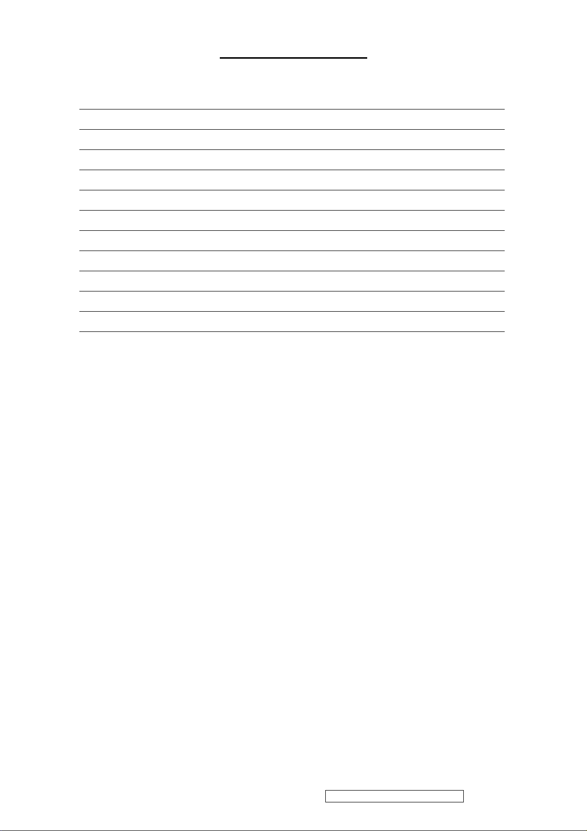
TABLE OF CONTENTS
1. Precautions and Safety Notices 1
2. Specification 4
3. Front Panel Function Control Description
4. Circuit Description 14
5. Adjustment Procedure 24
6. Troubleshooting Flow Chart 50
7. Block Diagram 51
8. Recommended Spare Parts List 61
9. Exploded Diagram and Exploded Parts List 65
10. Schematic Diagrams 66
11. PCB Layout Diagrams 72
11
ViewSonic Corporation Confidential – Do Not Copy VX712
ii
Page 4

1. Precautions and Safety Notices
1.1 SAFETY PRECAUTIONS
This monitor is manufactured and tested on a ground principle that a user’s safety comes first.
However, improper use or installation may cause damage to the monitor as well as the user.
Carefully go over the following WARNINGS before installing and keep this guide handy.
WARNINGS
.This monitor should be operated only at the correct power sources indicated on the label on
the rear end of the monitor. If you’re unsure of the power supply in your residence, consult
you local dealer or power company.
.Use only the special power adapter that comes with this monitor for power input.
.Do not try to repair the monitor your self as it contains no user-serviceable parts. This
monitor should only be repaired by a qualified technician.
.Do not remove the monitor cabinet. There is high-voltage parts inside that may cause electric
shock to human bodies, even when the power cord is unplugged.
.Stop using the monitor if the cabinet is damaged. Have it checked by a service technician.
.Put your monitor only in a clean, dry environment. If it gets wet, unplug the power
cableimmediately and consult your service technician.
.Always unplug the monitor before cleaning it .Clean the cabinet with a clean, dry cloth. Apply
non-ammonia based cleaner onto the cloth, not directly onto the glass screen.
.Keep the monitor away from magnetic objects, motors, TV sets, and transformer.
.Do not place heavy objects on the monitor or power cord.
1.2 PRODUCT SAFETY NOTICE
Many electrical and mechanical parts in this chassis have special safety visual inspections
and the protection afforded by them cannot necessarily be obtained by using replacement
components rated for higher voltages, wattage, etc. Before replacing any of these
components read the parts list in this manual carefully. The use of substitute replacement
parts which do not have the same safety characteristics as specified in the parts list may
create shock, fire ,or other hazards.
1.3 SERVICE NOTES
1. When replacing parts or circuit boards, clamp the lead wires around terminals before
soldering.
2. When replacing a high wattage resistor(more than 1W of metal oxide film resistor) in
circuit board, keep the resistor about 5mm away from circuit board.
3. Keep wires away from high voltage, high temperature components and sharp edges.
4. Keep wires in their original position so as to reduce interference.
5. Usage of this product please refer to also user’s manual.
ViewSonic Corporation Confidential – Do Not Copy VX712
1
Page 5
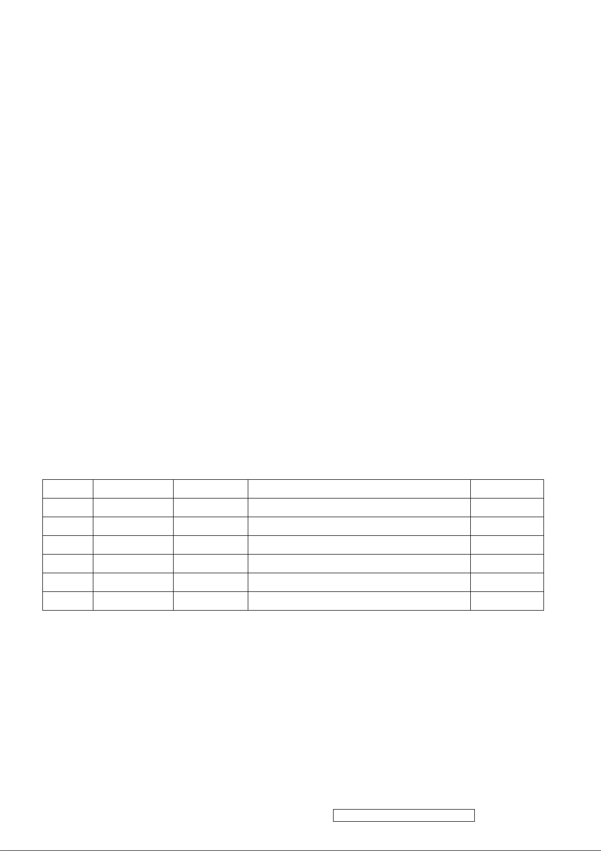
1.4 HANDING AND PLACING METHODS
Correct Methods: Incorrect Methods:
Only touch the metal frame of the LCD
panel or the front cover of the monitor. Do
not touch the surface of the polarizer.
Surface of the LCD panel is pressed by fingers
and that may cause “Mura. ”
Take out the monitor with cushions
Taking out the monitor by grasping the LCD
panel. That may cause “Mura.”
ViewSonic Corporation Confidential – Do Not Copy VX712
2
Page 6
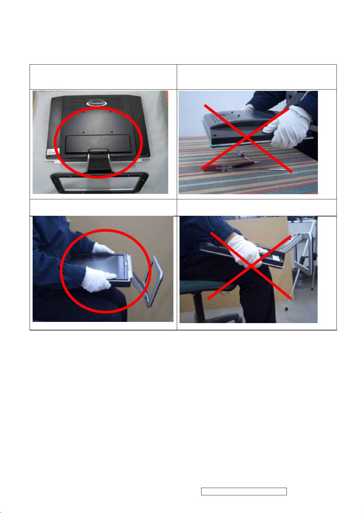
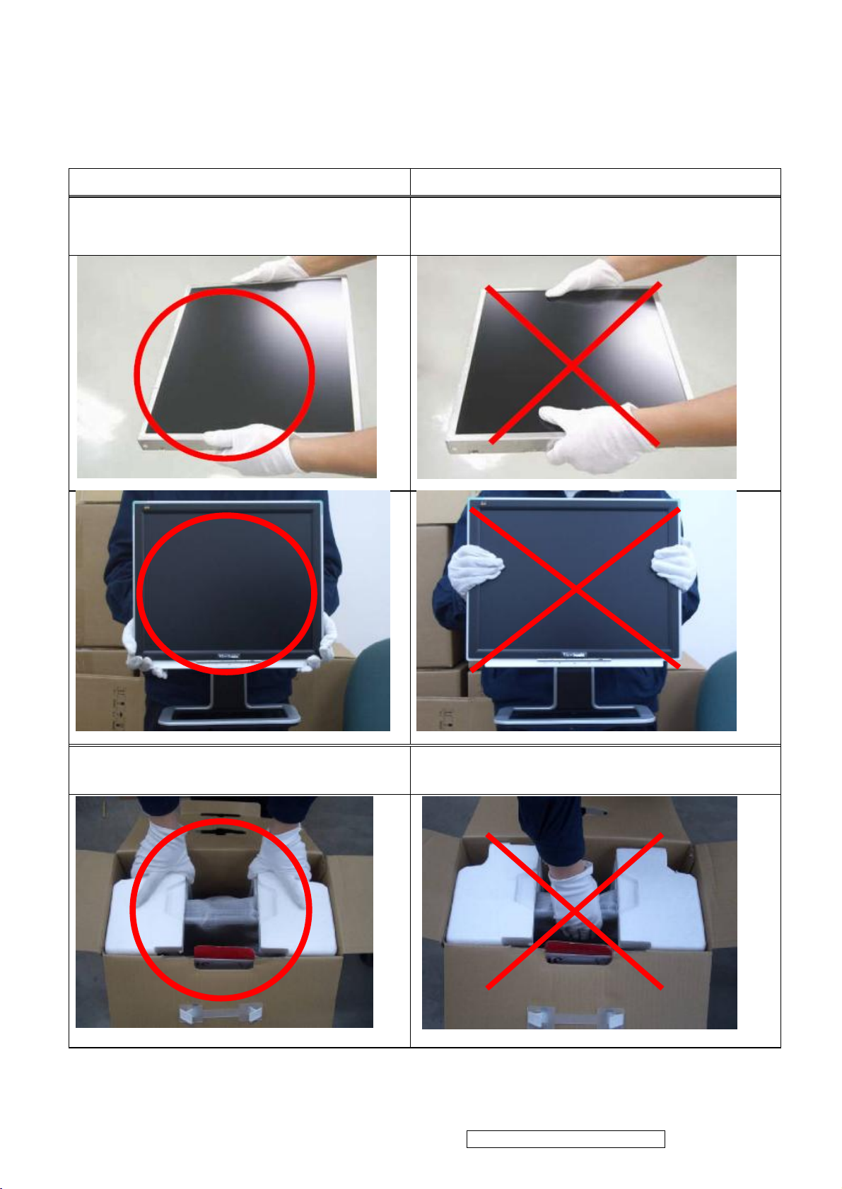
Place the monitor on a clean and soft foam
pad.
Placing the monitor on foreign objects. That
could scratch the surface of the panel or cause
“Mura.”
Place the monitor on the lap, the panel
surface must be upwards.
The panel is placed facedown on the lap. That
may cause “Mura.”
ViewSonic Corporation Confidential – Do Not Copy VX712
3
Page 7
2. Specification
2.1 PRODUCT SPECIFICATIONS
LCD Panel 17.0” TFT
Input Signal Analog / Digital
Pixel Dimension 0.264(H) x 0.264(V)mm
LCD Display Color 16.2M Colors (RGB 6-bit+FRC data)
Viewing Angle
Contrast Ratio
Horizontal: 150
Vertical: 135 °
700:1 (Typ.)
°
Brightness 300 cd/㎡(Typ.)
Response Time 8ms(Typ.)
Active Display Area 337.9 (H) x 270.3 (V)
Maximum Pixel Clock 135 MHz
Recommend Resolution 1280 x1024@60Hz
Horizontal Frequency 30 – 82 kHz
Vertical Refresh Rate 50 – 75 Hz.
Temperature
Audio Input 1 x 2 Watts
Power Management
Power
Operating: 0°C to +40°C
Storage: -20°C to +60°C
Energy Star compliant VESA
DPMS compatible
<1 W
Input Voltage : 90V~264V
Consumption: 40 Watts(Max.) 35 Watts(Typ.)
ViewSonic Corporation Confidential – Do Not Copy VX712
4
Page 8
2.2 FACTORY SUPPORTING MODES
Timing Table Primary Presets
Item Timing Analog Digital
1 640 x 350 @ 70Hz, 31.5kHz Yes Yes
2 640 x 400 @ 60Hz, 31.5kHz Yes Yes
3 640 x 400 @ 70Hz, 31.5kHz Yes Yes
4 640 x 480 @ 50Hz, 24.7kHz Yes Yes
5 640 x 480 @ 60Hz, 31.5kHz Yes Yes
6 640 x 480 @ 67Hz, 35.0kHz Yes Yes
7 640 x 480 @ 72Hz, 37.9kHz Yes Yes
8 640 x 480 @ 75Hz, 37.5kHz Yes Yes
9 640 x 480 @ 85Hz, 43.27kHz Yes Yes
10 720 x 400 @ 70Hz, 31.5kHz Yes Yes
11 800 x 600 @ 56Hz, 35.1kHz Yes Yes
12 800 x 600 @ 60Hz, 37.9kHz Yes Yes
13 800 x 600 @ 75Hz, 46.9kHz Yes Yes
14 800 x 600 @ 72Hz, 48.1kHz Yes Yes
15 800 x 600 @ 85Hz, 53.7kHz Yes Yes
16 832 x 624 @ 75Hz, 49.7kHz Yes Yes
17 1024 x 768 @ 60Hz, 48.4kHz Yes Yes
18 1024 x 768 @ 70Hz, 56.5kHz Yes Yes
19 1024 x 768 @ 72Hz, 58.1kHz Yes Yes
20 1024 x 768 @ 75Hz, 60.0kHz Yes Yes
21 1024 x 768 @ 85Hz, 68.67kHz Yes Yes
22 1152 x 864 @ 75Hz, 67.5kHz Yes Yes
23 1152 x 870 @ 75Hz, 68.7kHz Yes Yes
24 1280 x 1024 @ 60Hz, 63.4kHz Yes Yes
25 1280 x 1024 @ 75Hz, 79.97kHz Yes Yes
26 1280x 720 @ 60Hz, 45kHz (HDTV) Yes Yes
Primary Preset: VESA : 1280 x1024@60Hz
ViewSonic Corporation Confidential – Do Not Copy VX712
5
Page 9
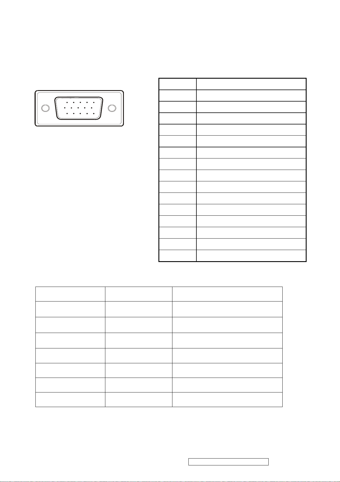
2.3 D-SUB CONNECTOR
D-SUB 15 PIN CONNECTOR
Pin Number Pin Function
15
6
11 15
SIGNAL LEVEL
1 Red video input
10
2 Green video input
3 Blue video input
4 No Connection
5 Ground
6 Red video ground
7 Green video ground
8 Blue video ground
9 +5V
10 H/V sync ground
11 No connection
12 (SDA)
13 Horizontal sync (Composite sync)
14 Vertical sync
15 (SCL)
CONNECTOR SIGNAL DESCRIPTION
R Red
G Green
B Blue
0.7
0.7
0.7
vp-p
(VIDEO)
vp-p
(VIDEO)
vp-p
(VIDEO)
H H/Sync TTL positive or negative
V V/Sync TTL positive or negative
SDA DDC1/2B TTL
SCL DDC1/2B TTL
ViewSonic Corporation Confidential – Do Not Copy VX712
6
Page 10
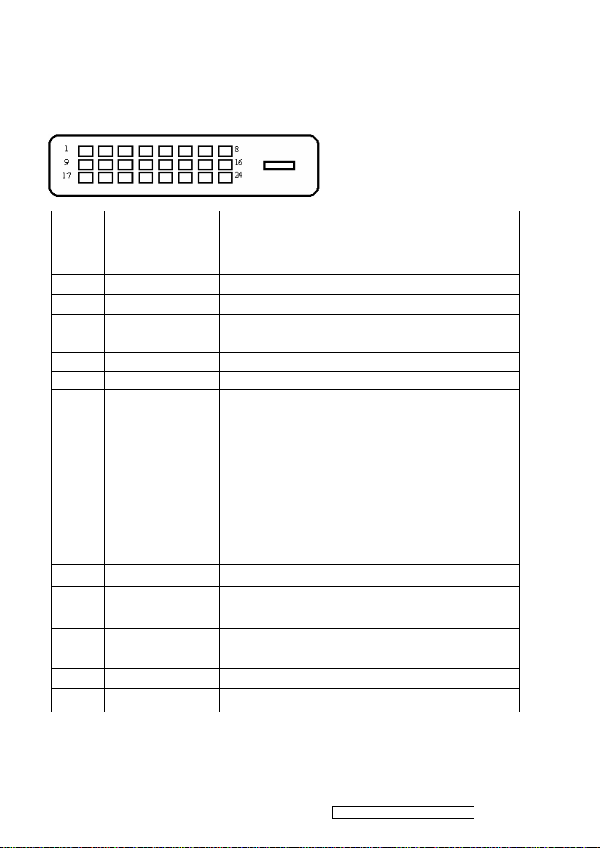
DVI-D 24 PIN CONNECTOR
Pin No.
Signal Name Description
1 RX2- TMDS negative differential input, channel 2
2 RX2+ TMDS positive differential input, channel 2
3 GND Logic Ground
4 Reserved 4 Reserved. No connection
5 Reserved 5 Reserved. No connection
6 DDC-CLK DDC2B Clock
7 DDC-DAT DDC2B Data
8 Reserved 8 Reserved. No connection
9 RX1- TMDS negative differential input, channel 1
10 RX1+ TMDS positive differential input, channel 1
11 GND Logic Ground
12 Reserved 12 Reserved. No connection
13 Reserved 13 Reserved. No connection
14 VCCX Power
15 GND Logic Ground
16 SENS SENSE Pin, Pull High
17 RX0- TMDS negative differential input, channel 0
18 RX0+ TMDS positive differential input, channel 0
19 GND Logic Ground
20 Reserved 20 Reserved. No connection
21 Reserved 21 Reserved. No connection
22 GND Logic Ground
23 RXC+ TMDS positive differential input, reference clock
24 RXC- TMDS negative differential input, reference clock
ViewSonic Corporation Confidential – Do Not Copy VX712
7
Page 11
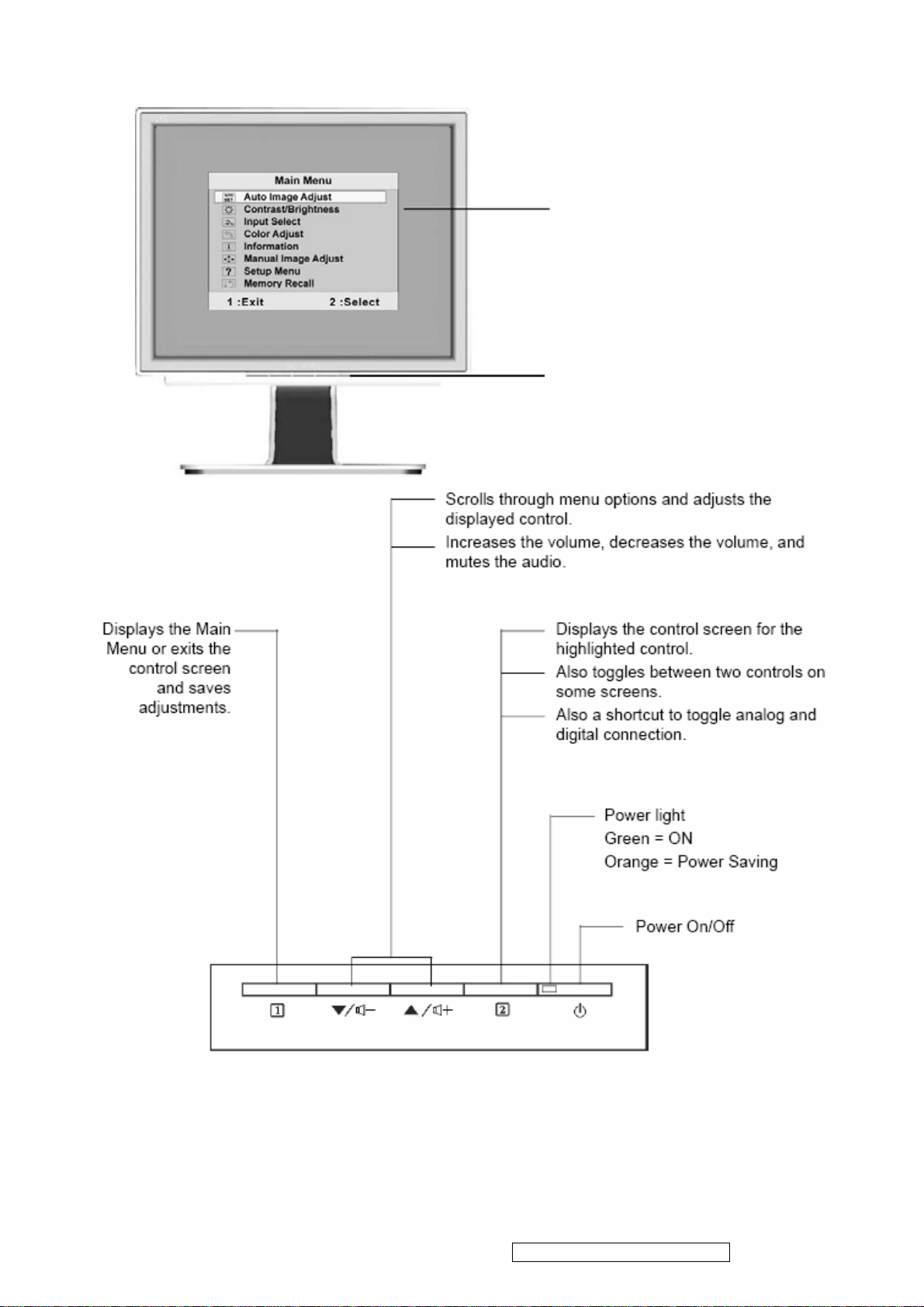
3. Front Panel Function Control Description
Main Menu
with OSD controls
Front Control Panel
shown below in detail
ViewSonic Corporation Confidential – Do Not Copy VX712
8
Page 12

Do the following to adjust the display setting:
g
1. To display the Main Menu, press button: [1]
NOTE: All OSD menus and adjustment screens disappear automatically after about 30
seconds. This is adjustable through the OSD timeout setting in the setup menu.
2. To select a control to adjust, press ▲ or ▼ to scroll up or down the Main Menu.
3. After the desired control is selected, press button [2]. A control screen like the one shown
below appears.
The line at the bottom of the screen shows
the current functions of buttons 1 and 2:
Exit or select the Bri
htness control.
4. To adjust the setting, press the up ▲ or down ▼ buttons.
5. To save the adjustments and exit the menu, press button [1] twice.
The following tips may help you optimize your display:
.Adjust your computer’s graphic card so that is outputs a 1280×1024@60Hz video signal to
the LCD display.(Look for instructions on “changing the refresh rate” in the graphics card’s
user guide.)
.If necessary, make small adjustments using H. Position and V. Position until the screen
image is completely visible.
(The black border around the edge of the screen should barely
touch is illuminated “active area” of the LCD display.)
ViewSonic Corporation Confidential – Do Not Copy VX712
9
Page 13
Main Menu Control
Adjust the menu items shown below by using up ▲ or down ▼ buttons.
Control explanation:
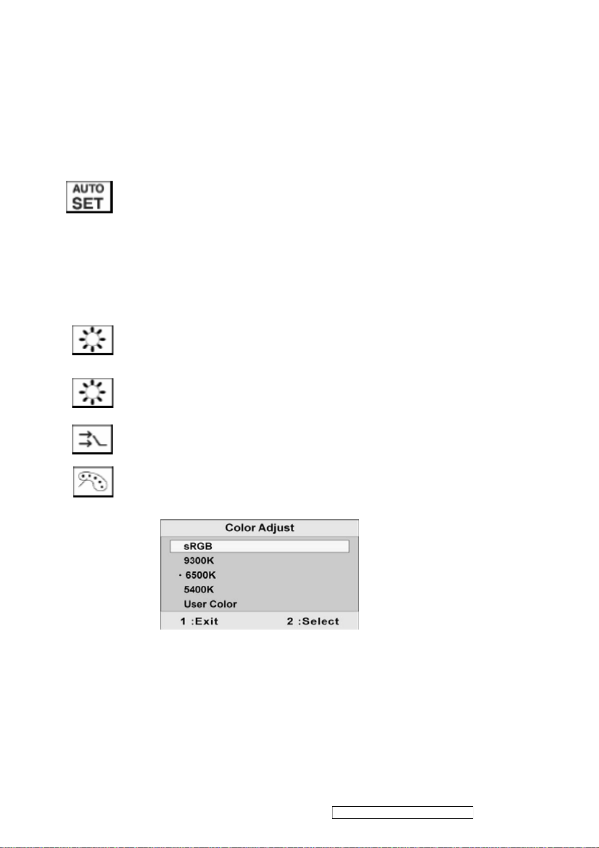
Auto Image Adjust automatically sizes, centers, and fine tunes the video
signal to eliminate waviness and distortion. Press the [2] button to obtain a
shaper image.
Note:
1. Auto Image Adjust works with most common video cards. If this function
does not work on your LCD display, then lower the video refresh rate to
60 Hz and set the resolution to its pre-set value.
2. The Auto Image Adjust and most Manual Image Adjust functions are not
available for DVI input.
Contrast adjust the different between the image background
(black level) and the foreground (white level).
Brightness adjusts background black level of the screen image.
Input Select allows the user to toggle between an analog and a digital signal.
Color Adjust provides several color adjustment modes, including preset
color temperatures and a User Color mode which allows independent
adjustment of red (R), green (G), and blue (B). The factory setting for this
product is 6500K (6500 Kelvin).
sRGB — sRGB is quickly becoming the industry standard for color
management, with support being included in many of the latest applications.
Enabling this setting allows the LCD display to more accurately display colors
the way they were originally intended. Enabling the sRGB setting will cause
the Contrast and Brightness adjustments to be disabled.
9300K — Adds blue to the screen image for cooler white (used in most office
setting with fluorescent lighting).
ViewSonic Corporation Confidential – Do Not Copy VX712
10
Page 14
6500K — Adds red to the screen image for warmer white and richer red.
5400K — Adds green to the screen image for a darker color.
User Color — Individual adjustments for red (R), green (G), and blue (B).
1. To select color (R, G or B) press button [2].
2. To adjust selected color , press ▲ or ▼.
Important: If you select RECALL from the Main Menu when the product is
set to a Preset Timing Mode, colors return to the 6500K factory preset.
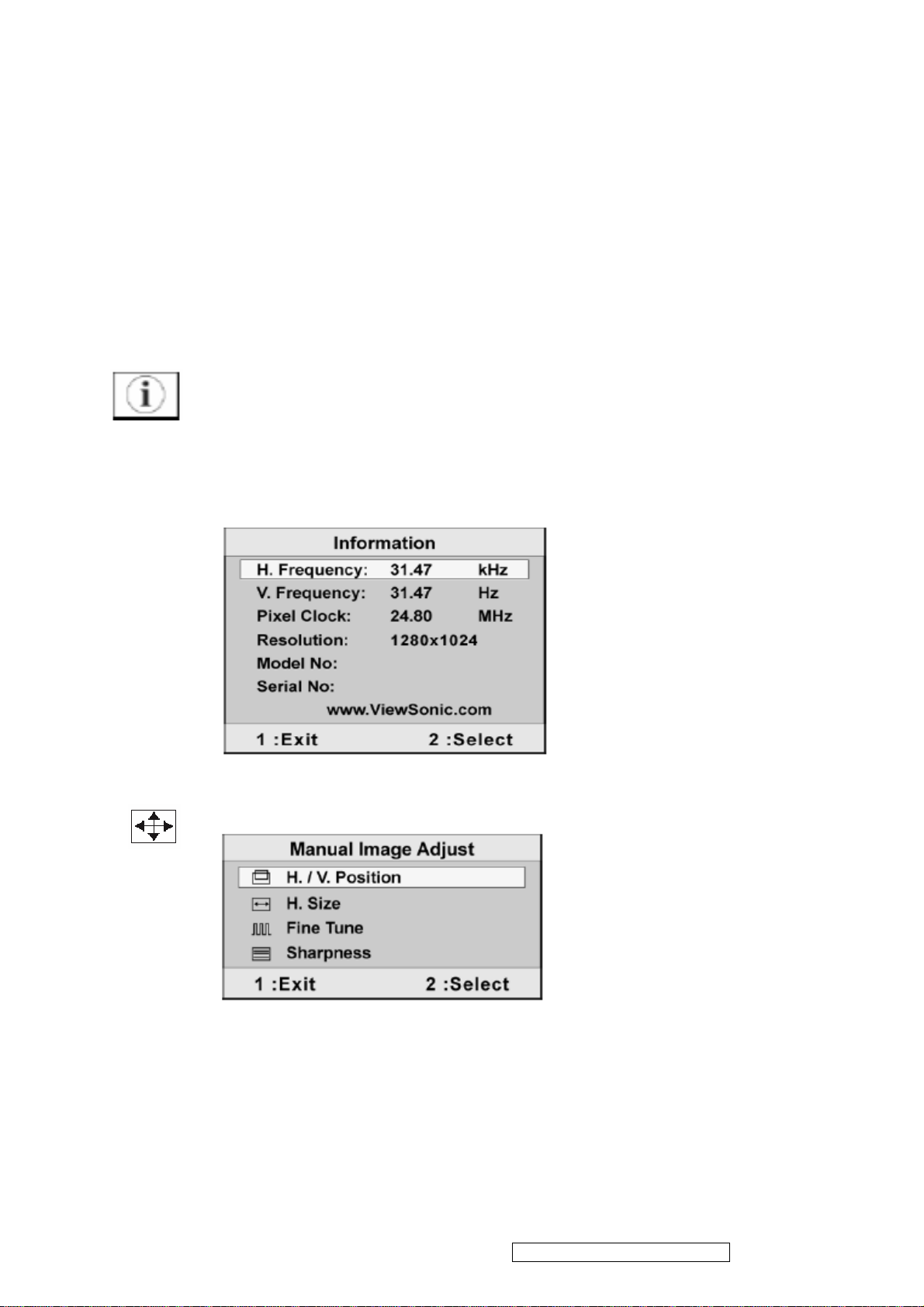
Information displays the timing mode (video signal input) coming from the
graphics card in the computer, the LCD model number, the serial number,
®
and the ViewSonic
website URL. See your graphics card’s user guide for
instructions on changing the resolution and refresh rate (vertical frequency).
NOTE: VESA 1280×1024@60Hz (rec ommended) means that the resolution
is 1280×1024 and the refresh rate is 60Hz.
Manual Image Adjust displays the Manual Image Adjust menu.
The Manual Image Adjust controls are explained below:
H./V. Position(Horizontal/Vertical Postion) moves the screen image left or
right and up or down.
H. Size(Horizontal Size) adjusts the width of the screen image.
ViewSonic Corporation Confidential – Do Not Copy VX712
11
Page 15
Fine Tune sharpens focus by aligning the text and/or graphics with pixel
boundaries.
Sharpness adjusts the clarity and focus of the screen image.
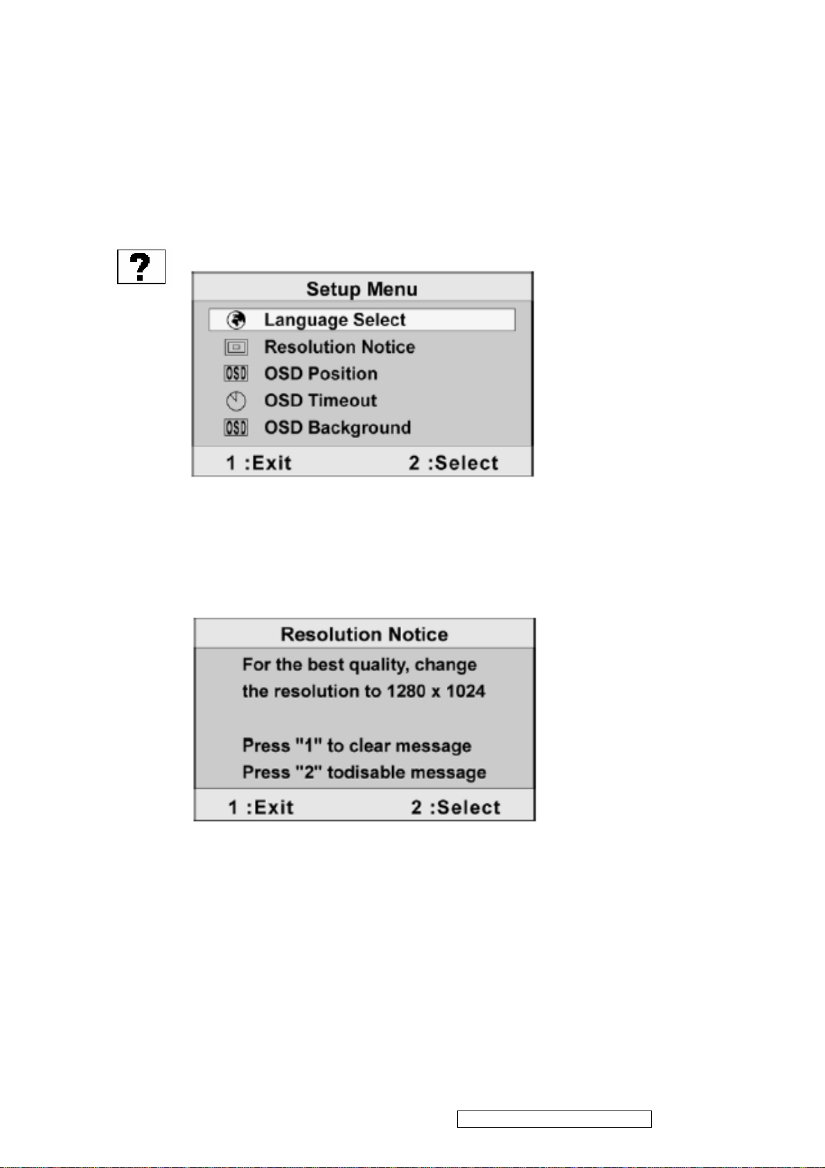
Setup Menu display the menu shown below.
The Setup Menu controls are explained below:
Language Select allows the user to choose the language used is the menus
and control screens.
Resolution Notice displays the Resolution Notice menu shown below.
Resolution Notice advises the optimal resolution to use.
OSD Position allows the user to move the OSD menus and control screens.
OSD Timeout sets the length of time the OSD screen is displayed. For
example, with a “15 second” setting, if a control is not pushed within 15
seconds, the display screen disappears.
OSD Background allows you to turn the OSD background On or Off.
ViewSonic Corporation Confidential – Do Not Copy VX712
12
Page 16
Memory Recall returns adjustments back to factory settings if the display is
operating in a factory Preset Timing Mode listed in the Specifications of this
manual.
Exception: This control does not affect changes mode with the User Color
control, Language Select or Power Lock setting.
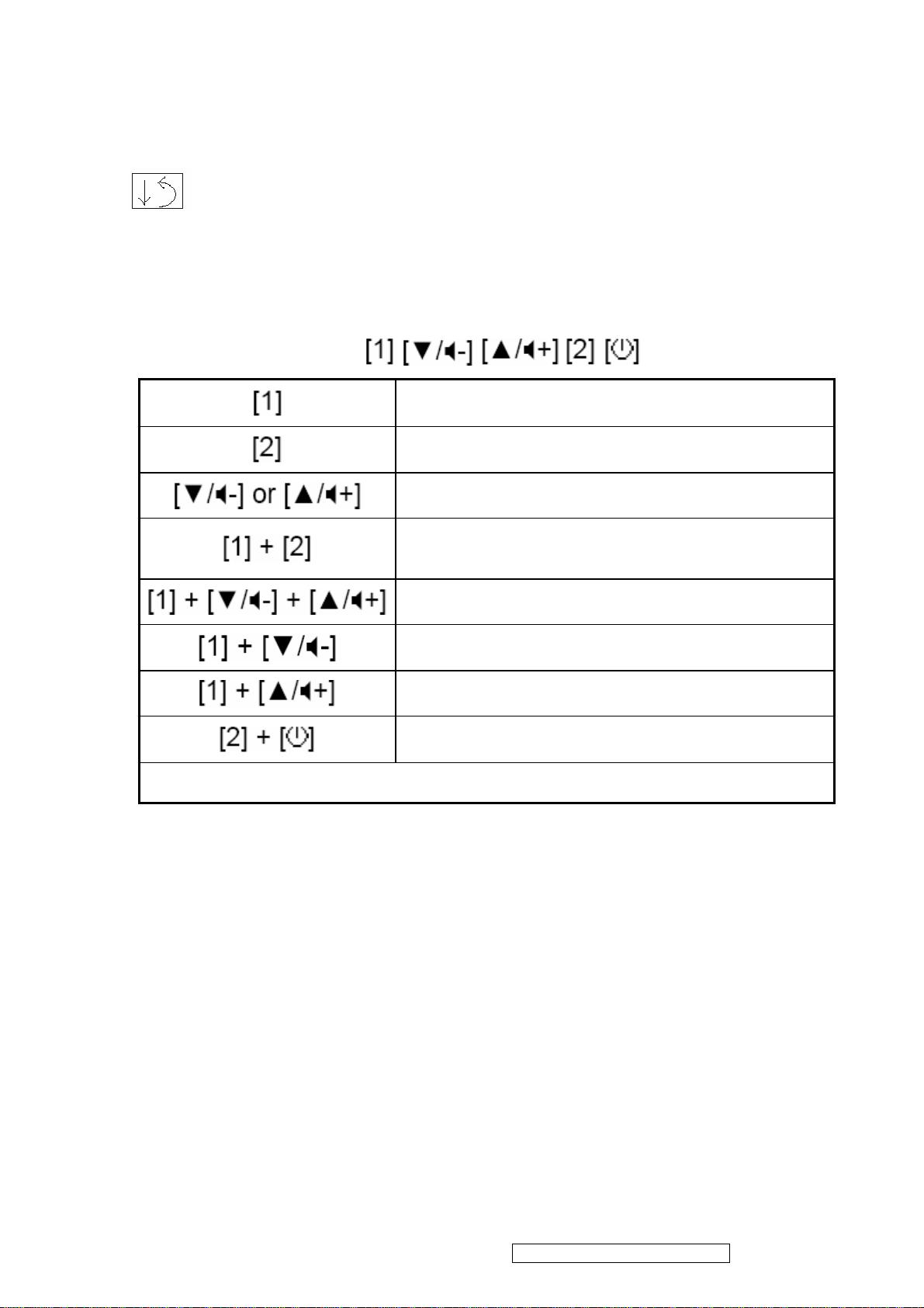
Short Cut Key
Function key: 5 keys
Remark : All the short cuts function are only available while OSD off.
Main Menu
Input toggle (Analog / Digital)
Audio Adjust
Toggle 720x400 and 640x400 mode when input
720x400 or 640x400 mode
White Balance. (Not shown on user’s guide)
Power Lock
OSD Lock
Factory Mode
ViewSonic Corporation Confidential – Do Not Copy VX712
13
Page 17
4. Circuit Description
Power Board
Flat Panel and
RS232 Connector
mode
AC-IN
OSC
Backli
ght and
P
anel
Keyboard
Audio board
OSC
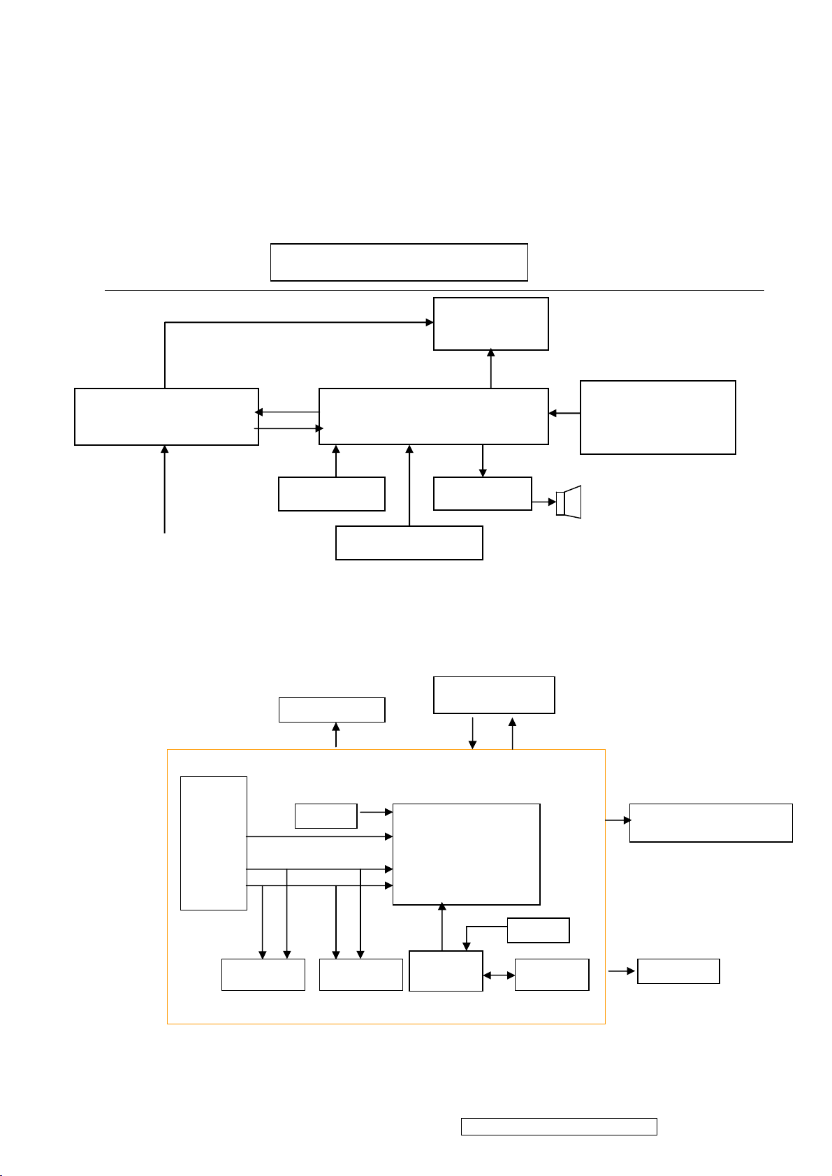
4.1 LCD MONITOR DESCRIPTION
The LCD MONITOR will contain a Main Board, an Power Board, an Audio Board, Key
Board which house the flat panel control logic, brightness control logic and DDC.
Monitor Block Diagram
(Include: adapter, inverter)
CCFL Drive.
CCFL backlight
Main Board
For white balance
adjustment in factory
Video signal, DDC
100V-240V
Key Board
Audio Board
HOST Computer
4.2 MAIN BOARD BLOCK FUNCTION DESCRIPTION
The main board contains panel control logic, brightness control logic, DDC and DC
convert DC circuit and so on.
R
G
B
H
V
SDA
SCL
PWPC board
RTD2523
ViewSonic Corporation Confidential – Do Not Copy VX712
EPROM EPROM
14
MCU
EPROM
Page 18
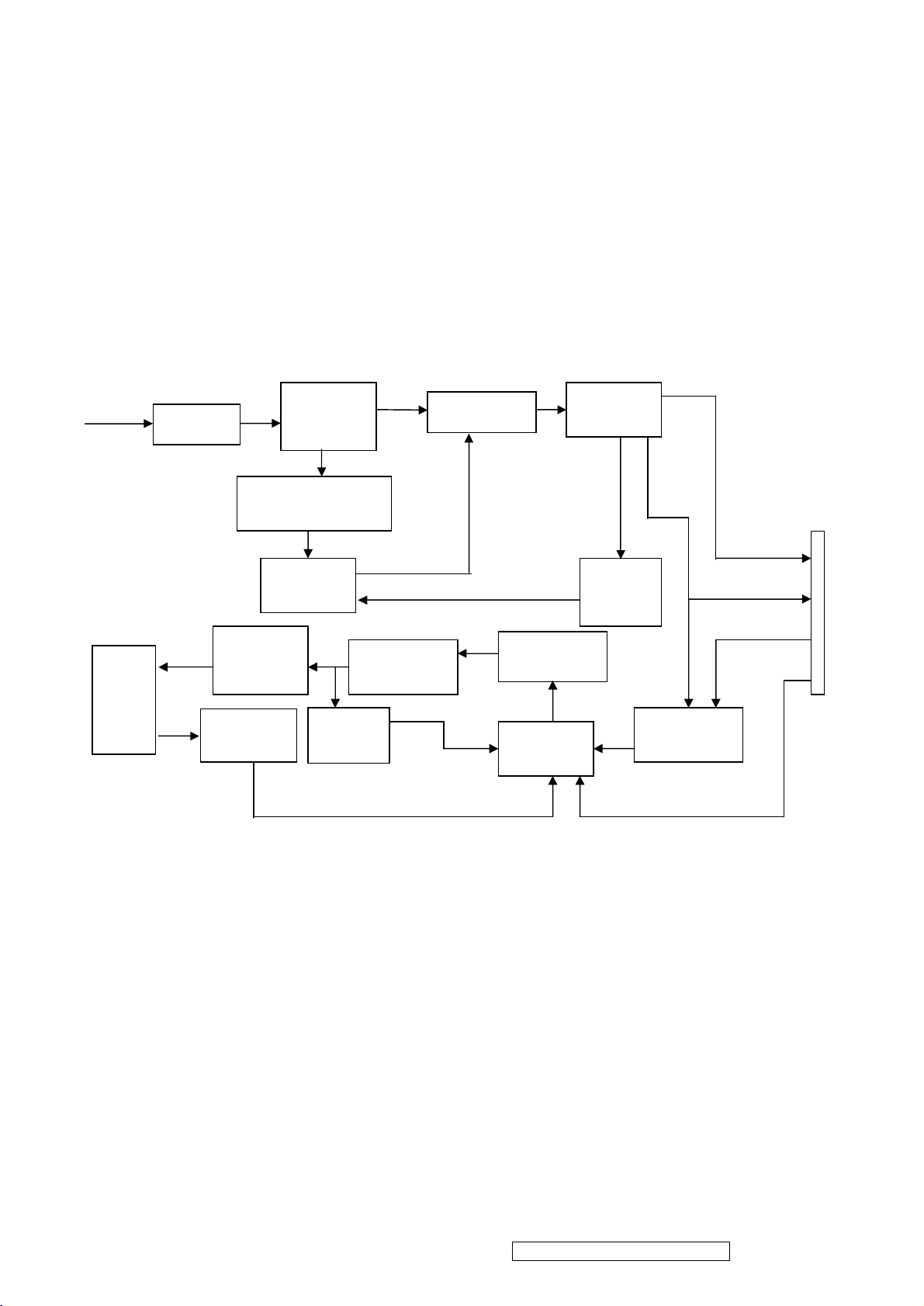
4.3 PWPC BOARD BLOCK FUNCTION DESCRIPTION
Start Circuit
PWM
Over
PWM
DC Convert
PWPC board combines to adapter and inverter, Adapter which commonly consists of
bridge rectifier and filter, start circuit, PWM control circuit, protection circuits and convert to
12V, 5V DC voltage by input 90V-240V AC voltage that provide power supply for each
chips in the main board and inverter. Inverter is DC TO AC circuit. It changes the 12v DC
of power supply to about 600-800v AC that drives the backlight. It mostly consists of
starting circuit, PWM controller, DC changing circuit, LC surging circuit, output circuit and
protection circuit etc.
AC input
EMI filter
Bridge
Rectifier
and Filter
Transformer
Rectifier
CMOS
Lamp
R903, R904,R905
Control IC
OSC and
Output
Circuit
Feedback
Circuit
Circuit
Over
Voltage
5V
12V
Voltage
Protect
ON/OFF
MOSFET
Q203
ON/OFF
Control
Control IC
DIM
CN902
ViewSonic Corporation Confidential – Do Not Copy VX712
15
Page 19
4.4 INTRODUCTION OF IC
RTD2523-LF(IC101): integrate ADC, OSD, SCALER, LVDS, convert analog RGB into
digital and room and shrink scaling output to LCD panel.
PIN Function:
Pin Symbol Description
1 XO Reference clock output
2 XI Reference clock input
3 DPLL_GND Ground for digital PLL
4 DPLL_VDD Power for digital PLL(3.3v)
5 APLL_VDD Power for multi-phase PLL(3.3v)
6 PLL_TEST1 Test Pin 1/IRQ#
7 PLL_TEST2 Test Pin 2/Power-on-latch for crystal
out Frequency
8 APLL_GND Ground for multi-phase PLL
9 PWM1/TMDS_TST PWM1/TMDS_TEST Pin/Power-on
latch for serial/parallel port
11、13、
TMDS_VDD 3.3V
19、26
12 EXT_RES Impedance Match Reference
14 RX2P Differential Data Input
15 RX2N Differential Data Input
17 RX1P Differential Data Input
18 RX1N Differential Data Input
20 RX0P Differential Data Input
21 RX0N Differential Data Input
23 RXCP Differential Data Input
24 RXCN Differential Data Input
51 PWM2/TCON[2]/S[3] PWM2/TCON[2]/SDIO[3]
55 PWM2/TCON[13]/COUT PWM2/TCON[13]/Crystal out
113 PWM2/TCON[12]/COUT PWM2/TCON[12]/Crystal out
47 PWM1/DDCSDA/TCON[1]/BBLU[0] PWM1/DDC serial control I/F data
input/output/TCON[4]
125 PWM1/DDCSDA2/TCON[7] PWM1/DDC serial control I/F data
input/output/TCON[7]
112 PWM0 / REFCLK PWM0(In/out)test pin for DCKL/Video
8 even-odd signal
54 SDIO[0] Serial control I/F data in/Parallel port
data[0]
53 SDIO[1]/TCON[4]/BBLU[0] Parallel port data[1]/TCON[4]/TTL
BBLU[0]
52 SDIO[2]/TCON[3]/BBLU[1] Parallel port data[2]/TCON[3]/TTL
BBLU[1]
51 SDIO[3]/PWM2/TCON[2] Parallel port data[1]/TCON[4]/PWM2
50 SCLK Serial control I/F clock
ViewSonic Corporation Confidential – Do Not Copy VX712
16
Page 20
111 SCSB Serial control I/F chip select
56 RESET RESET putput for Micron
46 DDCSCL / TCON[0] / BBLU[1] DDC serial control I/F clock/TCON[0]/
TTL BBLU[1]
47 DDCSDA / TCON[1] / pWM1 /
BBLU[0]
DDC serial control I/F data input/out/
CON[1] / Pwm1/TTL BBLU[0]
126 DDCSCL2 / TCON[5] DDC serial control I/F clock /
TCON[5]
125 DDCSDA2 / TCON[7] / pWM1 DDC serial control I/F data
input/out/TCON[7] / pWM1
28 ADC_REFIO ADC band-gap voltage de-coupling
29 ADC_VDD Analog power(3.3v)
30 BLUE+ Analog input from BLUE channel
31 BLUE- Analog input ground from BLUE
channel
33 SOG / ADC_ TEST SOG in / ADC test pin
34 GREEN+ Analog input from GREEN channel
35 GREEN- Analog input ground from GREEN
channel
36 ADCB_VDD Analog power(3.3V)
37 RED+ Analog input from RED channel
38 RED- Analog input ground from RED
channel
41 ADC_VDD Analog power(3.3V)
42 AHS Analog HS input
43 AVS Analog VS input
49、121
58、71、
3.3V Power VCCIO: 2
3.3V Power PVCC: 5
83、95、
110
45、69、
2.5V Power VCCK: 4
98、127
AIC1084-33PM (U101): DC power convert, used to 5v convert 3.3v.
RT9164(U102): DC power convert, used to 5v convert 2.5v.
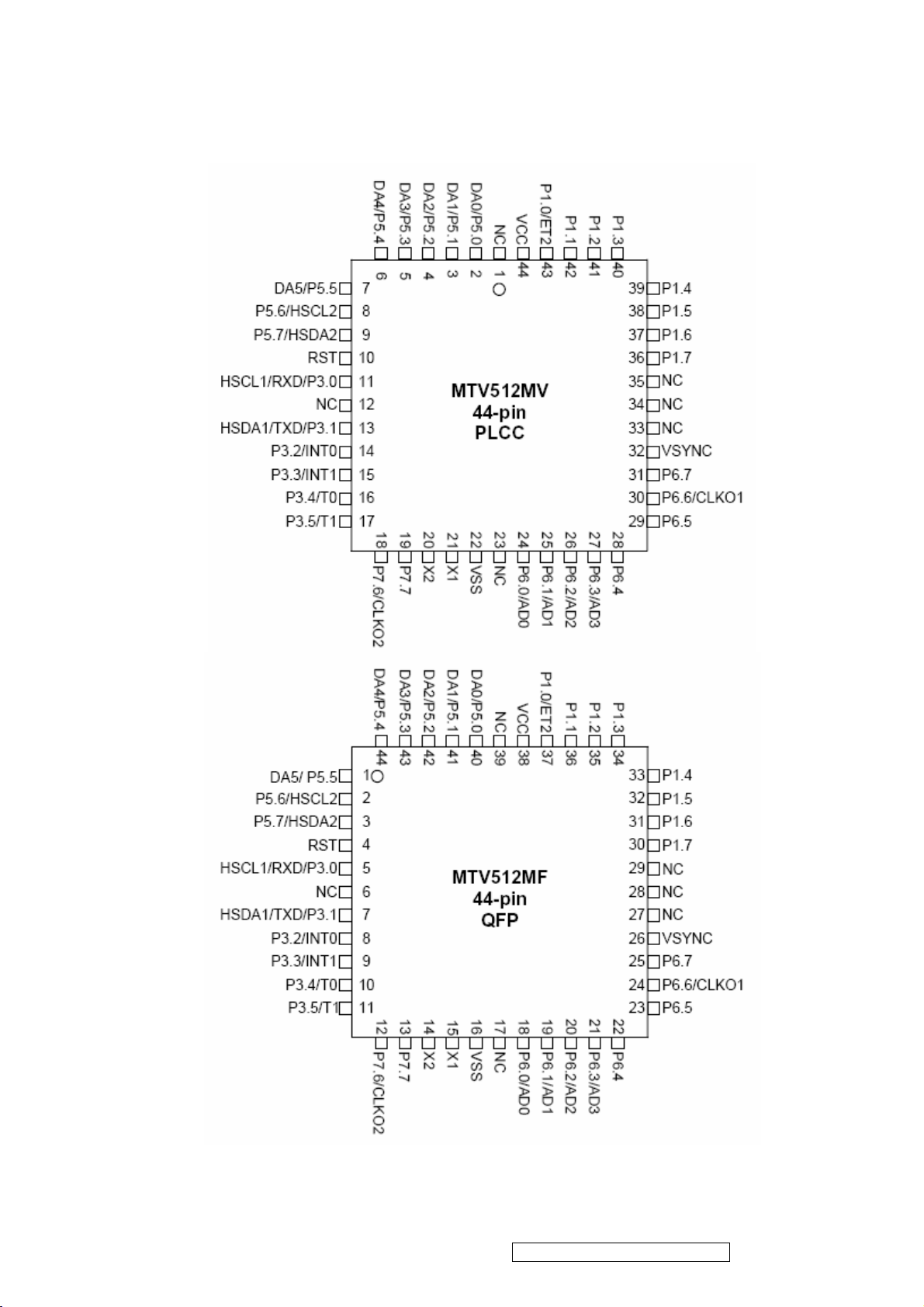
MTV512GMV64(U104):The MTV512M micro-controller is an 8051 CPU core embedded
device especially tailored for flat panel display applications. It includes an 8051
CPU core, 768-byte SRAM, 4 channels of 6-bit ADC, 3 external
counters/timers, 6 channels of PWM DAC, VESA DDC interface, and a
64K-byte internal program Flash-ROM memory.
ViewSonic Corporation Confidential – Do Not Copy VX712
17
Page 21
ViewSonic Corporation Confidential – Do Not Copy VX712
18
Page 22
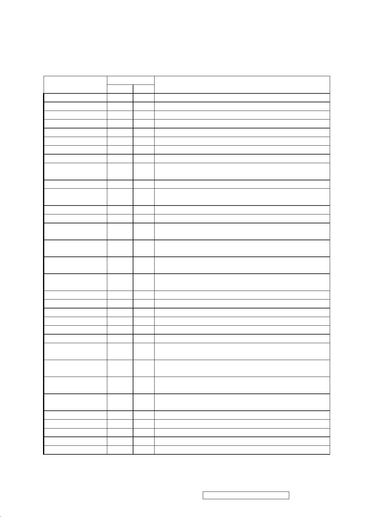
PIN Function
4
HSCL1/P3.0/RXD
5
7
8
9
Name
Pin No.
PLCC QFP
Description
NC 1 39 No connection
DA0/P5.0 2 40 PWM DAC output/General purpose I/O (open drain)
DA1/P5.1 3 41 PWM DAC output/General purpose I/O (open drain)
DA2/P5.2 4 42 PWM DAC output/General purpose I/O (open drain)
DA3/P5.3 5 43 PWM DAC output/General purpose I/O (open drain)
DA4/ P5.4 6 44 PWM DAC output/General purpose I/O (open drain)
DA5/P5.5 7 1 PWM DAC output/General purpose I/O (open drain)
P5.6/HSCL2 8 2 General purpose I/O/Slave IIC1 SCL2 (open drain)
P5.7/HSDA2 9 3
RST 10
11
HSDA1/P3.1/TXD
13
General purpose Output/Slave IIC1 SDA2 (open
drain)
High Active RESET
Slave IIC clock/General purpose I/O/Rxd (open
drain)
Slave IIC data/General purpose I/O/Txd (open drain)
CN 12 6 No connection
P3.2/INT0 14
P3.3/INT1 15
P3.4/T0 16
P3.5/T1 17
P7.6/CLKO2 18
P7.7 19
X2 20
X1 21
VSS 22
General purpose I/O/External interrupt 0 (Standard
8051)
General purpose I/O/External interrupt 1 (Standard
8051)
General purpose I/O/T0 Ext. Counter/Timer 0
10
(Standard 8051)
General purpose I/O/T1 Ext. Counter/Timer 1
11
(Standard 8051)
12 General purpose I/O /Clock out 2 (CMOS)
13 General purpose I/O (CMOS)
14 Crystal Out
15 Crystal In
16 Ground
NC 23 17 No connection
P6.0/AD0 24
P6.1/AD1 25
P6.2/AD2 26
P6.3/AD3 27
P6.4 28
P6.5 29
P6.6/CLKO1 30
P6.7 31
VSYNC 32
General purpose I/O (CMOS) /6-bit ADC channel 0
18
input
General purpose I/O (CMOS) /6-bit ADC channel 1
19
input
General purpose I/O (CMOS) /6-bit ADC channel 2
20
input
General purpose I/O (CMOS) /6-bit ADC channel 3
21
input
22 General purpose I/O (CMOS)
23 General purpose I/O (CMOS)
24 General purpose I/O/CLKO1 (CMOS)
25 General purpose I/O (CMOS)
26 VSYNC input
ViewSonic Corporation Confidential – Do Not Copy VX712
19
Page 23
NC 33 27 No connection
NC 34 28 No connection
NC 35 29 No connection
P1.7 36
P1.6 37
P1.5 38
P1.4 39
P1.3 40
P1.2 41
P1.1 42
P1.0/ET2 43
VCC 44
30 General purpose I/O (Standard 8051/CMOS)
31 General purpose I/O (Standard 8051/CMOS)
32 General purpose I/O (Standard 8051/CMOS)
33 General purpose I/O (Standard 8051/CMOS)
34 General purpose I/O (Standard 8051/CMOS)
35 General purpose I/O (Standard 8051/CMOS)
36 General purpose I/O (Standard 8051/CMOS)
General purpose I/O/External Counter/Timer2
37
(Standard 8051/CMOS)
38 3.3V power
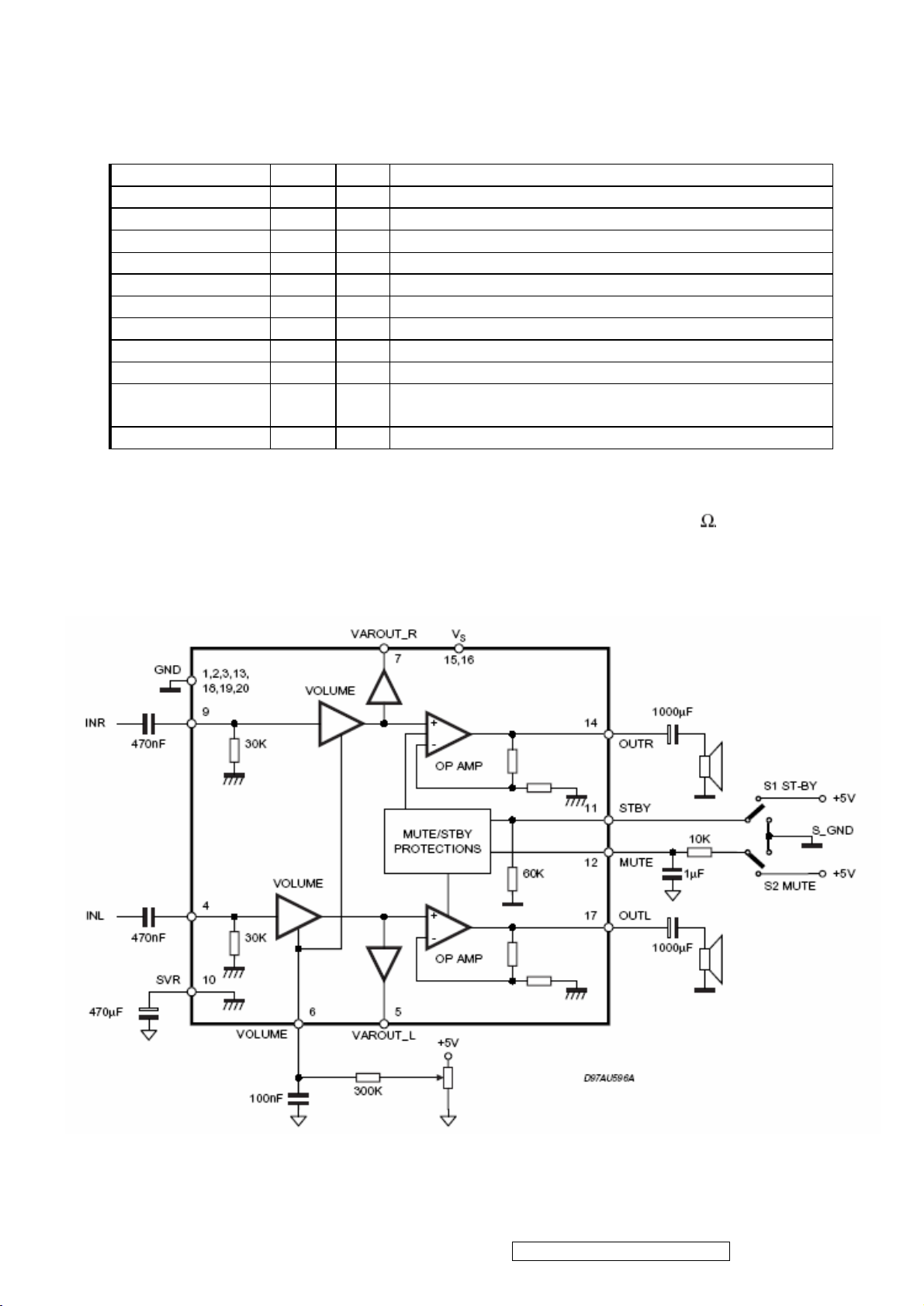
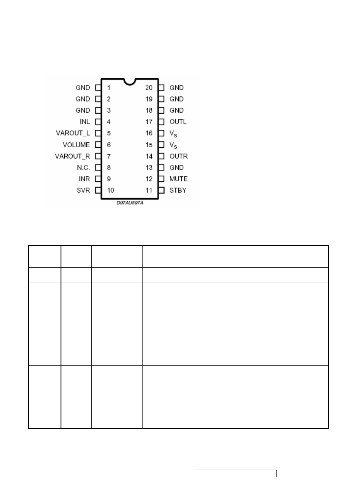
TDA7496L(U201): The TDA7496L is a stereo 2W+2W class AB power amplifier
assembled in the @ Powerdip, driving speakers as low as 8 . The function of
each pin and the inside circuit diagram are as follows:
Block Diagram
ViewSonic Corporation Confidential – Do Not Copy VX712
20
Page 24
PIN Function
SG6841 (IC901): This highly integrated PWM controllers, Low start up current 30 uA. The
circuit unit has functions such as over-current protection, over-temperature protection,
over-voltage protection, output short-circuit protection and etc. The function of each pin
and the inside circuit diagram are as follows:
Pin/ No.
Pin
Name
Function Pin Description
1 GND Ground Ground.
2 FB Feedback
3 VIN Start-Up
4 Ri
Reference
Setting
The signal from external compensation circuit is feed into
this pin. The PWM duty cycle is determined by this FB pin
and current sense signal from Pin 6.
This pin is pulled high to the rectified line input through a
resistor for start-up. Since the start-up current requirement
for SG6841 is very small, a large start-up resistance can
be used to minimize power loss. Under normal operation,
this pin is also used to detect line voltage to compensate
for constant output power limit for universal AC input.
A resistor from RI pin to ground will generate a constant
current source for SG6841. This current is used to charge
an internal capacitor and hence the switching frequency
are determined. Increasing the resistance will decrease the
current source and reduce the switching frequency,. A 26k
Ω resistor R1 creates a 50uA constant current L1 and
generates 65kHz switching frequency.
ViewSonic Corporation Confidential – Do Not Copy VX712
21
Page 25

5 RT
Temperature
Protection
For over-temperature protection. An external NTC
thermistor is connected from this pin to ground. The
impedance of the NTC will decrease under high
temperature. Once the voltage on RT pin drops below a
fixed limit, the PWM output will be disabled.
6 SENSE Current Sense
Current sense. The sensed voltage is used for current
mode control and pulse-by-pulse current limiting.
7 VDD Power supply Power Supply.
8 GATE Driver Output
The totem-pole output driver for the power MOSFET. A soft
driving waveform is implemented to improve EMI.
Block Diagram
ViewSonic Corporation Confidential – Do Not Copy VX712
22
Page 26

TL1451(U201): PWM control, voltage range for working: 3.6~35V, Has such functions as
short-voltage protection, Over-voltage protection, over-current protection and etc.
The function of each pin and the circuit diagram inside are as follows:
Pin Symbol
1 CT
2 RT
3 1IN+
4 1IN-
5 1FBK
6 1DTC
7 1OUT
8 GND
Description Pin Symbol
External timing capacitor
External timing resistor
Positive input for error amplifier 1
Positive input for error amplifier 2
Error amplifier 1 output
Output 1 dead time/soft start
setting
Output 1
Ground
9 VCC
10 2OUT
11 2DTC
12 2FBK
13 2IN+
14 2IN-
15 SCP
16 REF
Description
Power supply
Output 2
Output 2 dead time/soft start setting
Error amplifier 2 output
Positive input for error amplifier
Positive input for error amplifier
Timing latch setting
Reference voltage output (2.5v)
ViewSonic Corporation Confidential – Do Not Copy VX712
23
Page 27

5. Adjustment Procedure
5.1 ADJUSTMENT CONDITIONS AND PRECAUTIONS
1. Approximately 30 minutes should be allowed for warm up before proceeding.
2. Adjustments should be undertaken only on those necessary elements since most of them
have been carefully preset at the factory.
3. ESD protection is needed before adjustment.
5.2 MAIN ADJUSTMENTS
NO. FUNCTIONS DESIGNATION
1. White Balance Function Key
2. GEOMETRY Function Key
5.3 ALIGNMENT PROCEDURES
Approximately 30 minutes should be allowed for warm up before proceeding
White-Balance adjustment.
1.Adjust of White Balance
1.)、How to do the Chroma-7120 MEM .Channel setting
A、Reference to chroma 7120 user guide
B、Use “ SC” key and “ NEXT” key to modify xyY value and use “ID” key to modify the
TEXT description Following is the procedure to do white-balance adjust
2)、Setting the color temp. You want
A、MEM.CHANNEL9 ( 9300 color):
9300 color temp. parameter is Wx = 0.283 ±0.03;Wy = 0.298 ±0.03;
Y = 250 ±20 cd/m
2 ,
B、MEM.CHANNEL10 ( 6500 color):
6500 color temp. parameter is Wx = 0.313±0.03;Wy = 0.329 ±0.03;
2,
Y = 250 ±20 cd/m
C、MEM.CHANNEL 11 ( 5400 color):
5400 color temp. parameter is Wx = 0.335±0.03;Wy = 0.350 ±0.03;
2,
Y = 250 ±20 cd/m
3)、Into factory mode of VX712
A、First Power off, then press Switch 2 button along with press Power button will activate
the factory mode, then MCU will do AUTO LEVEL automatically. Meanwhile press
MENU the OSD screen will located at LEFT TOP OF PANEL.
ViewSonic Corporation Confidential – Do Not Copy VX712
24
Page 28

4)、Bias adjustment :
Set the Contrast
Adjust the Brightness
to 70
to 100.
5)、Gain adjustment :
Move cursor to “-F-” and press MENU key
A、Adjust 9300 color-temperature
(1)、Switch the Chroma-7120 to RGB-Mode (with press “MODE” button )
(2)、Switch the MEM. channel to Channel 9 ( with up or down arrow on chroma 7120 )
(3)、The LCD-indicator on chroma 7120 will show x = 0.283 ±0.03, y =0.298 ±0.03,
2
Y = 250 ±20 cd/m
(4)、Adjust the RED of color1 on factory window until chroma 7120 indicator reached
the value R=100
(5)、Adjust the GREEN of color1 on factory window until chroma 7120 indicator
reached the value G=100
(6)、Adjust the BLUE of color1 on factory window until chroma 7120 indicator reached
the value B=100
(7)、Repeat above procedure ( item 4,5,6) until chroma 7120 RGB value meet the
tolerance =100±5
B、Adjust 6500 color-temperature
(1)、Switch the chroma-7120 to RGB-Mode (with press “MODE” button )
(2)、Switch the MEM .channel to Channel 10( with up or down arrow on chroma 7120 )
(3)、The LCD-indicator on chroma 7120 will show x = 0.313 ±0.03, y = 0.329 ±0.03, Y
2
= 250 ±20 cd/m
(4)、Adjust the RED of color3 on factory window until chroma 7120 indicator reached
the value R=100
(5)、Adjust the GREEN of color3 on factory window until chroma 7120 indicator
reached the value G=100
(6)、Adjust the BLUE of color3 on factory window until chroma 7120 indicator reached
the value B=100
(7)、Repeat above procedure ( item 4,5,6) until chroma 7120 RGB value meet the
tolerance =100±5
C、Adjust 5400 color-temperature
(1) Switch the chroma-7120 to RGB-Mode (with press “MODE” button )
(2)、Switch the MEM .channel to Channel 11( with up or down arrow on chroma 7120 )
(3)、The LCD-indicator on chroma 7120 will show x = 0.335 ±0.03, y = 0.350 ±0.03, Y
2
= 250 ±20 cd/m
ViewSonic Corporation Confidential – Do Not Copy VX712
25
Page 29

(4)、Adjust the RED of color3 on factory window until chroma 7120 indicator reached
the value R=100
(5)、Adjust the GREEN of color3 on factory window until chroma 7120 indicator
reached the value G=100
(6)、Adjust the BLUE of color3 on factory window until chroma 7120 indicator reached
the value B=100
(7)、Repeat above procedure ( item 4,5,6) until chroma 7120 RGB value meet the
tolerance =100±5
D、Press reset key and Turn the Power-button “off to on” to quit from factory mode.
2. Geometry
1).Set cross-hatch pattern and preset timing as timing table listed.
2).Change to each mode in turn and wait for the monitor finish auto-alignment and save
press before change to next mode.
3).Until all of modes are adjusted,exit OSD menu and press PWR OFF to exit factory
mode.
ViewSonic Corporation Confidential – Do Not Copy VX712
26
Page 30

5.4 Factory Defaults
Item Defaults Item Defaults
Contrast 70% Sharpness 33%
Brightness 100% OSD H. Position 50%
Volume 50% OSD V. Position 50%
Balance 50% OSD Time Out 15 Sec
Bass 50% OSD Background On
Treble 50% OSD PIVOT Off
Color Temperature 6500K Resolution Notice Enabled
720x400/640x400 720x400
5.5 Function Test
1 Product: 17” LCD Monitor
2 Test Equipment: Color Video Signal & Pattern (or PC with SXGA resolution and a sound
card)
3 Test Condition: Before function test and alignment, each LCD Monitor should be warmed
up for at least 30 minutes with the following conditions:
(a)In room temperature,
(b) With full-white screen, RGB, and Black
(c) With cycled display modes,
640*480 (H=43.27kHz, V=85Hz)
800*600 (H=53.7kHz, V=85Hz)
1024*768 (H=68.67kHz, V=85Hz)
1280*1024 (H=79.97kHz, V=75Hz)
4 Test Display Modes & Pattern
Compatible Modes
Item
Timing Analog Digital
1 640 x 350 @ 70Hz, 31.5kHz Yes Yes
2 640 x 400 @ 60Hz, 31.5kHz Yes Yes
3 640 x 400 @ 70Hz, 31.5kHz Yes Yes
4 640 x 480 @ 50Hz, 24.7kHz Yes Yes
5 640 x 480 @ 60Hz, 31.5kHz Yes Yes
6 640 x 480 @ 67Hz, 35.0kHz Yes Yes
7 640 x 480 @ 72Hz, 37.9kHz Yes Yes
8 640 x 480 @ 75Hz, 37.5kHz Yes Yes
9 640 x 480 @ 85Hz, 43.27kHz Yes Yes
ViewSonic Corporation Confidential – Do Not Copy VX712
27
Page 31

10 720 x 400 @ 70Hz, 31.5kHz Yes Yes
11 800 x 600 @ 56Hz, 35.1kHz Yes Yes
12 800 x 600 @ 60Hz, 37.9kHz Yes Yes
13 800 x 600 @ 75Hz, 46.9kHz Yes Yes
14 800 x 600 @ 72Hz, 48.1kHz Yes Yes
15 800 x 600 @ 85Hz, 53.7kHz Yes Yes
16 832 x 624 @ 75Hz, 49.7kHz Yes Yes
17 1024 x 768 @ 60Hz, 48.4kHz Yes Yes
18 1024 x 768 @ 70Hz, 56.5kHz Yes Yes
19 1024 x 768 @ 72Hz, 58.1kHz Yes Yes
20 1024 x 768 @ 75Hz, 60.0kHz Yes Yes
21 1024 x 768 @ 85Hz, 68.67kHz Yes Yes
22 1152 x 864 @ 75Hz, 67.5kHz Yes Yes
23 1152 x 870 @ 75Hz, 68.7kHz Yes Yes
24 1280 x 1024 @ 60Hz, 63.4kHz Yes Yes
25 1280 x 1024 @ 75Hz, 79.97kHz Yes Yes
26 1280x 720 @ 60Hz, 45kHz (HDTV) Yes Yes
Function Test Display Pattern
Item Test Content Pattern Specification Remark
1
Frequency &
Tracking
Fine Line Moire
2 Contrast/Brightness 16 Gray Scale
Eliminate visual wavy
noise.
16 gray levels sh should
be distinguishable.
Figure 1
Figure 2
Horizontal and Vertical
3 Boundary
Horizontal&Vertical
Thickness
position of video should
be adjustable to be
Figure 3
within the screen frame.
RGB Color
4
Performance
Screen Uniformity &
5
Flicker
6 Dead Pixel/Line
RGB Color Intensities
Full White
White Screen & Dark
Screen
Contrast of each R, G,
B, color should be
normal.
Should be compliant
with the spec.
The numbers of dead
pixels should be
compliant with the spec.
Figure
4,5,6
Figure 7
Figure
7,8
The screen must have
7 White Balance White & Black Pattern
the pure white and black
Figure 9
pattern, no other color.
ViewSonic Corporation Confidential – Do Not Copy VX712
28
Page 32

Fine Line Morie Pattern (Figure1) Gray Scale Pattern (Figure2)
Horizontal & Vertical Thickness Pattern R. Color Pattern (Figure 4)
(Figure 3)
G. Color Pattern (Figure 5) B. Color Pattern (Figure 6)
ViewSonic Corporation Confidential – Do Not Copy VX712
29
Page 33

Full White Pattern (Figure 7) Dark Screen Pattern (Figure 8)
Black-White Pattern (Figure 9)
4.3 Function Test and Alignment Procedure
All Modes Reset
You should do “All Mode Reset” (Refer to Chapter III-3. Hot Keys for Function
Controls) first. This action will allow you to erase all end-user’s settings and restore
the factory defaults.
Auto Image Adjust
Please select and enter “Auto Image Adjust” function on Main Menu to see if it is
workable. The “Auto Image Adjust” function is aimed to offer a better screen quality
by built-in ASIC. For optimum screen quality, the user has to adjust each function
manually.
Firmware
Test Pattern: Burn In Mode (Refer to Chapter III-3. Hot Keys for Function Controls)
- Make sure the F/W is the latest version.
DDC
Test Pattern: EDID program
Make sure it can pass test program.
ViewSonic Corporation Confidential – Do Not Copy VX712
30
Page 34

Fine Tune and Sharpness
Test Signal: 1280*1024@60Hz
Test Pattern: Line Moire Pattern
Check and see if the image has noise and focus performs well. Eliminate visual line
bar.
If not, readjust by the following steps:
(a)Select and enter “Fine Tune” function on “Manual Image Adjust” to adjust the
image to eliminate visual wavy noise.
(b)Then, select and enter “Sharpness” function to adjust the clarity and focus of the
screen image.
Boundary
Test Signal: 1280*1024@60Hz
Test Pattern: Horizontal & Vertical Line Thickness Pattern
Check and see if the image boundary is within the screen frame.
If not, readjust by the following steps:
(a)Select and enter “Manual Image Adjust” function on OSD Main Menu.
(b)Then, select and enter “Horizontal Size” or “Horizontal/Vertical Position” function to
adjust the video boundary to be full scanned and within screen frame.
White Balance
Test Signal: 640*480@60Hz
Test Pattern: White and Black Pattern
1.5.8 R, G, B, Colors Contrast
Test Signal: 1280*1024@60Hz
Test Pattern: R, G, B, Color Intensities Pattern and 16 Gray Scale Pattern
- Check and see if each color is normal and distinguishable.
- If not, please return the unit to repair area.
Screen Uniformity and Flicker
Test Signal: 1280*1024@60Hz
Test Pattern: Full White Pattern
- Check and see if it is in normal condition.
1.5.10 Dead Pixel and Line
Test Signal: 1280*1024@60Hz
Test Pattern: Dark and White Screen Pattern
- Check and see if there are dead pixels on LCD panel with shadow gauge and filter
film.
- The total numbers and distance of dead pixels should be compliant with the spec.
Mura
Test Pattern: White, RGB, Black, & Grey
Test Tool: 10% ND Filter
- Check if the Mura can pass 10% ND Filter.
Audio
Test Signal: Voice signal (optional, depend on model)
Test Pattern: liberty
- Make sure there is audio output.
- Make sure that audio function (volume 80%) is working without noise and
resonance.
- Make sure that the sound of right and left speakers are in balance.
ViewSonic Corporation Confidential – Do Not Copy VX712
31
Page 35

Check for Secondary Display Modes
Test Signal:
Analog: 640*350@70Hz; 640*480@60/67/72/75/85Hz;
720*400@70Hz; 800*600@56/60/72/75/85Hz;
832*624@75Hz, 1024*768@60/70/72/75/85Hz;
1280*1024@60/75Hz
Digital: 640*350@70Hz; 640*480@60/72/75/85Hz;
720*400@70Hz; 800*600@56/60/72/75/85Hz;
1024*768@60/70/72/75/85Hz; 1152*870@75Hz,
1280*720@60Hz, 1280*1024@60Hz
- Normally when the primary mode 1280*1024@60Hz is well adjusted and
compliant with the specification, the secondary display modes will also be compliant
with the spec. But we still have to check with the general test pattern to make sure
every secondary is compliant with the specification.
-
All Modes Reset
After final QC step, we have to erase all saved changes again and restore the factory
defaults. You should do “All Mode Reset” again.
Power Off Monitor
Turn off the monitor by pressing “Power” button.
5.6 Firmware Upgrade Procedure
When you receive the returned monitor, please check whether the firmware version is the
latest. If not, please do the following procedures to upgrade it to the latest version.
1 Equipment Needed
- VX712 Monitor
- Fixture for Firmware Upgrade
- VGA Cable (P/N: 42.59901.003) *1(Pin 4, 11 should be connected to GND)
- PC (Personal Computer)
- LPT Cable (P/N: 42.59906.001) *1
- Firmware Upgrade Program
- One additional monitor for checking the program execution
ViewSonic Corporation Confidential – Do Not Copy VX712
32
Page 36

2 Setup Procedure
2.1 Connect P2 of Fixture with printer port of PC by LPT Cable.
2.2 Connect P1 of Fixture with VX712 Monitor by VGA Cable.
2.3 Connect Power Cord to VX712 Monitor.
2.4 Connect P3 to the Signal Generator (eg.Chroma2326) for verifying it after the
operation being completed.
2.5 Connect PC to the additional monitor.
P3: to Signal Generator
P1: to VGA Cable
P2: to LPT Cable
ViewSonic Corporation Confidential – Do Not Copy VX712
33
Page 37

3 Firmware Upgrade Procedure
Step 1. Install the Myson ISP program.
3.1.1 User could download ISP install file from Myson Century
website( //www.myson.com.tw )
3.1.2 After extracting the zip file, the total files list as Fig 3.1, and double click the file of
setup.exe to install.
Fig 3.1.2
3.1.3 Press “Next” button to continue, see Fig 3.1.3.
Fig 3.1.3
ViewSonic Corporation Confidential – Do Not Copy VX712
34
Page 38

3.1.4 Keep default setting or press “Change” button for selecting the path that you want,
and then press “Next” button to continue, see Fig 3.1.4.
Fig 3.1.4
3.1.5 Press “Install” button to continue, see Fig 3.1.5
Fig 3.1.5
ViewSonic Corporation Confidential – Do Not Copy VX712
35
Page 39

3.1.6 The Installer Information shows package warning, press “Ignore” button to continue,
see Fig 3.1.6.
Fig 3.1.6
3.1.7 Installation has finished, press “Finish” button, see Fig 3.1.7.
Fig 3.1.7
Step 2. ISP security code setting.
ViewSonic Corporation Confidential – Do Not Copy VX712
36
Page 40

3.2.1 After installation, we could find the shortcut in the setting path or the program bar
(default setting), see Fig 3.2.1.
Fig 3.2.1.
3.2.2 Press “Create Security File” button to key in security code. Adjusting bar to
decrease speed of IIC bus, see Fig 3.2.2.
Fig 3.2.2.
ViewSonic Corporation Confidential – Do Not Copy VX712
37
Page 41

3.2.3 Fig 3.2.3 shows the setting for security code of hardware ISP, it needs 4 Command
No, and key in command sequentially for 94, 94, AC, CA, 53.
Fig 3.2.3
Step 3. Let VX712 set to be connected with AC cable and VGA cable.
Step 4. Use ISP to program MCU.
4.3.1 Select MTV type first, load the binary or Intel hex file that you want to program into
the MCU, and select “Auto” item, then press “RUN” button, see Fig 4.3.1.
4.3.2 If user changes the MTV type, it must load file again, or the buffer of load file will be
cleared.
4.3.3 CRC (cyclic redundancy check): the host can check CRC register’s result instead of
reading every byte in flash. The message of “Check MCU CRC OK” means that the Host
verify ok for the progress of program.
ViewSonic Corporation Confidential – Do Not Copy VX712
38
Page 42

“Check MCU CRC OK”
Fig 4.3.1
Step 5. Unplug and replug power cord of VX712 set and then check the OSD operation
and image on srceen.
Step 6. At last, do “Memory Recall.”
ViewSonic Corporation Confidential – Do Not Copy VX712
39
Page 43

3.2 Setup Procedure
3.2.1 Connect P2 and P4 of Fixture with VGA ports of VX712 by VGA Cable.
3.2.2 Connect P3 of Fixture with DVI port of VX712 by DVI-DVI Cable.
3.2.3 Connect P1 of Fixture with Printer port of PC by LPT Cable.
3.2.4 Plug Power Adapter to Fixture.
3.2.5 Connect Power Cord to VX712 Monitor.
3.2.6 Connect PC to the additional monitor.
P3:DVI-DVI Cable
P1:to LTP Cable
JP1: Power Adapter
P2: VGA Cable
ViewSonic Corporation Confidential – Do Not Copy VX712
40
Page 44

3.3 DDC Key In Procedure
Sep1.Select and execute DDc Key In program
ViewSonic Corporation Confidential – Do Not Copy VX712
41
Page 45

Sep2:Inpute the S/N and execute “Enter”
ViewSonic Corporation Confidential – Do Not Copy VX712
42
Page 46

ViewSonic Corporation Confidential – Do Not Copy VX712
43
Page 47

Sep3:Key the “Enter” and write the data
ViewSonic Corporation Confidential – Do Not Copy VX712
44
Page 48

Sep4:If ddc program OK and show “data compare ok”
ViewSonic Corporation Confidential – Do Not Copy VX712
45
Page 49

Disassemble Process
1. Tools
Glove
Cross screwdriver
Prize equipment or abandoned IC card
Bolt box
Cushion
2. Disassemble process
1、 Tide up the worktable, spread straight cushion, put the monitor on it, the front side
adown.(Picture 1)
2、 Remove the decorate slice of the back cover.(Picture 2)
3、 Remove the decorate slice of the stand.(Picture 3)
4、 Disassemble the 4 screws that fix the stand, remove the stand.(Picture 4)
5、 Disassemble the 4 screws of the back cover.(Picture 5)
6、 Use equipment or abandoned IC card to prize up the bezel through the bottom flute,
as showed in the following the picture 6, and rip up the bezel downwards.(Attention to
the fixed hook position between bezel and back cover, as showed in the following the
picture 7,8,9,10,11,12)
7、 Disassemble the 2 fixed screws and the 2 pins of the KEY board, and remove the
back cover, as showed in the following the picture 13,14,15.
8、 Disassemble the fixed screws in the shield, remove the shield as the direction
arrowhead showed, refer to the following picture 16.
9、 Disassemble the 6 screws and 4 pins of the PWPC board, remove the PWPC
board.(symbolized the following picture 17 with red color)
10、 Disassemble the 3 screws and 4 pins of the main board, remove the main board.
(symbolized the following picture 17 with blue color)
11、 Disassemble the 2 screws of the audio board, remove the audio board. (symbolized
the following picture 17 with yellow color)
12、 Disassemble the 4 fixed screws of the panel, remove the main frame, as showed in
the following the picture 19,20,21. Do not damage the cable of the panel.
13、 That’s all. The disassemble process of the unit is over.
ViewSonic Corporation Confidential – Do Not Copy VX712
46
Page 50

3. Show pictures:
(Picture 1) (Picture 2)
(Picture 3) (Picture 4)
(Picture 5) (Picture 6)
(Picture 7)
(Picture 8)
(Picture 9)
(Picture 10)
ViewSonic Corporation Confidential – Do Not Copy VX712
47
Page 51

(Picture 11) (Picture 12)
(Picture 13)
(Picture 14)
(Picture 15) (Picture 16)
ViewSonic Corporation Confidential – Do Not Copy VX712
48
Page 52

(Picture 17)
(Picture 19)
(Picture 18) (Picture 20)
(Picture 21)
ViewSonic Corporation Confidential – Do Not Copy VX712
49
Page 53

6. Troubleshooting Flow Chart
ViewSonic Corporation Confidential – Do Not Copy VX712
50
Page 54

7. Recommend Spare Part List
Serial No. Prefix: Q4P
Accessories:
53
BUCKET-R-COVER
PL-00005000
34G1327 KS B
1
All revised RSPLs with newly added items or any change made should be highlighted and correlated with the ECN/ECR
RECOMMENDED SPARE PARTS LIST (VX712-1)
ViewSonic Model Number: VS10057-1W
Rev: 1a
Item ECR/ECN ViewSonic P/N Ref. P/N Location Universal number# Q'ty
1
2 AUPC BOARD B-00004963 AUPC780B3P 1
Board Assembly:
3 CONVERSINON BOARD B-00004964 CBPC782KAWVWP 1
4 KEY BOARD B-00004965 KEPC780KK9P 1
5 POWER BOARD B-00004966 PWPC1742AUV1P 1
6 BEZEL C-00004967 34G1320 KS B 1
Cabinets:
7 MIDDLE BEZEL C-00004968 34G1321BKD B 1
8 REAR COVER C-00004969 34G1322 KS 2B 1
9 WIRE HARNESS CB-00004970 95G8014 12 12 1
Cables:
10 AUDIO BOARD HARNESS CB-00004971 95G8014 14927 1
11 AUDIO CABLE CB-00004972 89G 173 56 31 1
12 SIGNAL CABLE CB-00003768 89G 728HAA902 1
13 CABLE CB-00004973 95G8018 30552 1
14 CD MANUAL DC-00004974 70G170170911A 1
Documentation:
15 CARTON LABEL DC-00003727 40G 459709 1B 1
16 S/N LABEL DC-00003734 40G 459709 2B 1
17 H/V WARNING LABEL DC-00003729 40G 459709 4A 1
18 HI-POT LABEL FOR 17-LCD DC-00003731 40G 459709 5A 1
19 ID VX712(AU) DC-00004975 40G 97070910A 1
20 Hg LABEL DC-00003730 40G457B709 1A 1
21 8ms STICKER DC-00003498 40G581B709 3A 1
22 QSG DC-00004976 41G780170910A 1
23 17" LCD PANEL AUO E-00004977 750GLU70G01 2 1
Electronic
24 RTD2523-LF PQFP-128 E-00004978 56G 562 75 IC101 1
Components:
25 IC AP1084K33LA E-00004979 56G 563 21 U101 1
26 IC LDO RT9164-25PL E-00004980 56G 585 7 U102 1
27 IC MTV512GMV64 E-00004981 56G1125543AWW U104 1
28 IC M24C02-WMN6TP E-00003738 56G1133 34 U106 1
29 IC M24C16-WMN6TP E-00004982 56G1133 56 U105 1
30 SPEAKER E-00004983 78G322A 1 L 1
31 SPEAKER E-00004984 78G322A 1 R 1
32 EVA WASHER HW-00004989 44G3231 15547 1
Hardware:
33 HINGE HW-00004986 37G 497500 1
34 MAIN FRAME HW-00004985 15G8019 1 1
35 SCREW HW-00004987 M1G 140 6120 8
36 SCREW HW-00004988 M1G 330 6128 4
37 SCREW HW-00004990 M1G1030 6128 2
38 SCREW HW-00004991 M1G1140 6120 1
39 SCREW HW-00003747 M1G1730 6128 2
40 SCREW HW-00004992 M1G2130 4 47 4
41 SCREW HW-00004993 Q1G1030 8128 4
42
Miscellaneous:
43 EPS(L) P-00004995 44G3734 1 1
Packing Material:
44 EPS(R) P-00004996 44G3734 2 1
45 PE BAG P-00003757 45G 76 28 V3 1
46 PE BAG P-00003758 45G 88607 1
47 EPE COVER P-00003753 45G 88609 4 1
48 EPE COVER P-00003754 45G 88609 B 1
49 CARTON P-00004997 C 44G3734709 4A 1
50 STAND M-MS-0808-9573 34G1323 KD B 1
Plastics:
51 STAND-F-COVER PL-00004998 34G1325 KR B 1
52 STAND-R-COVER PL-00004999 34G1326 KR B 1
Description
POWER CORD A-00004962 89G404A18N LS 1
BASE DIE CASTING
M-00004994 20G 013 1 1
Remark 1:
Above listed items are examples, supplier can expand the rows to add more necessary items.
Remark 2:
ViewSonic Corporation Confidential – Do Not Copy VX712
51
Page 55

Serial No. Prefix: Q4P
LABEL
S/N LABEL
A
Hg LABEL
YELLOW TAPE
PROTECT FILM
MYLAR
SHIELD
SIGNAL CABLE
WIRE HARNESS
AUDIO BOARD HARNESS
CABLE
SCREW M4X6
BOM LIST (VX712-1)
ViewSonic Model Number: VS10057-1W
Rev: 1a
Item ViewSonic P/N Ref. P/N Description Location Universal number# Q'ty
1 B-00004963 AUPC780B3P AUDIO BOARD 1
2 B-00004964 CBPC782KAWVWP CONVERSION BOARD 1
3 B-00004965 KEPC780KK9P KEY BOARD 1
4 B-00004966 PWPC1742AUV1P POWER BOARD 1
5 M-00002677 11G6054 1 PIN CONNECTOR 4
6 #N/A 12G 394600 FOOT PORON 4
7 #N/A 15G8012 4 BASE 1
8 #N/A 23G3178709 2A VSC17-LCD BACKCOVER 1
9 #N/A 23G3178709 3A VSC17-LCD FRONT LOGO 1
10 #N/A 23G3178709 4A VSC17-LCD FRONT LOGO 1
11 PL-00004999 34G1326 KR B STAND-R-COVER 1
12 PL-00005000 34G1327 KS B BUCKET-R-COVER 1
13 #N/A 40G 45760819A
14 DC-00003727 40G 459709 1B CARTON LABEL 1
15 DC-00003734 40G 459709 2B
16 DC-00003729 40G 459709 4A H/V WARNING LABEL 1
17 DC-00003731 40G 459709 5A HI-POT LABEL FOR 17-L 1
18 #N/A 40G 58162435A MANUAL P/N LABEL 1
19 DC-00004975 40G 97070910A
20 DC-00003730 40G457B709 1A
21 DC-00003498 40G581B709 3A 8ms STICKER 1
22 DC-00004976 41G780170910A QSG 1
23 HW-00004989 44G3231 15547 EVA WASHER 1
24 P-00004995 44G3734 1 EPS 1
25 P-00004996 44G3734 2 EPS 1
26 P-00003757 45G 76 28 V3 PE BAG 1
27 #N/A 45G 77 3 TRANSPARENT SHEET 73
28 P-00003758 45G 88607 PE BAG 1
29 P-00003753 45G 88609 4 EPE COVER 1
30 P-00003754 45G 88609 B EPE COVER 1
31 #N/A 50G 600 1 W TAPE 74
32 #N/A 50G 600 2 HANDLE1 1
33 #N/A 50G 600 3 HANDLE2 1
34 #N/A 52G 1185 MIDDLE TAPE FOR CARTO 60
35 #N/A 52G 1185 24 TAPE 65
36 #N/A 52G 1186 SMALL TAPE 8
37 #N/A 52G 1207 A ALUMINIUM TAPE 1
38 #N/A 52G 2191 D TAPE 75
39 M-00002678 52G6019 1
40 #N/A 52G6020800
41 #N/A 52G6025 11655 MYLAR 1
42 #N/A 52G6025 11675
43 DC-00004974 70G170170911A CD MANUAL 1
44 E-00004983 78G322A 1 L SPEAKER 1
45 E-00004984 78G322A 1 R SPEAKER 1
46 #N/A 85G 583509 VS COTTON 1
47 #N/A 85G 662 2
48 CB-00004972 89G 173 56 31 AUDIO CABLE 1
49 CB-00003768 89G 728HAA902
50 A-00004962 89G404A18N LS POWER CORD 1
51 CB-00004970 95G8014 12 12
52 CB-00004971 95G8014 14927
53 CB-00004973 95G8018 30552
54 HW-00004987 M1G 140 6120
55 HW-00004988 M1G 330 6128 SCREW 4
56 HW-00004990 M1G1030 6128 SCREW 2
57 HW-00004991 M1G1140 6120 SCREW 1
58 HW-00003747 M1G1730 6128 SCREW 2
59 HW-00003747 M1G1730 6128 SCREW 8
60 HW-00003747 M1G1730 6128 SCREW 2
1
1
1
1
10
1
1
1
1
1
1
1
8
ViewSonic Corporation Confidential – Do Not Copy VX712
52
Page 56

Item ViewSonic P/N Ref. P/N Description Location Universal number# Q'ty
AUDIO AI BOARD
AUDIO SMT BOARD
WAFER&PLUG
DHIP 0.1UF 50V X7R
MAIN BOARD
WAFER
WAFER 2*6P 2.0MM R/A
Electric cotton
Electric cotton
61 HW-00004992 M1G2130 4 47 SCREW 4
62 HW-00004993 Q1G1030 8128 SCREW 4
63 #N/A 705G782KB3459R BEZEL ASS'Y 1
64 E-00004977 750GLU70G01 2 17" LCD PANEL 1
65 P-00004997 C 44G3734709 4A CARTON 1
#N/A NO : AUPC780B3P AUDIO BOARD
66 #N/A AUPC780A7AIP
67 #N/A AUPC780A7SMTP
68 #N/A 12G 408 6 THERMAL PAD 1
69 #N/A 33G801714A
70 #N/A 56G 616 1 AMPLIFIER IC E-TDA749 U201 1
71 #N/A 61G 60222452T 220KOHM 5% 1/6W R212 1
72 #N/A 67G215L471 3N 470UF/16V C205 1
73 #N/A 67G215L471 3N 470UF/16V C207 1
74 #N/A 67G215L471 3N 470UF/16V C208 1
75 #N/A 67G215L681 4N 680UF 25V C201 1
76 #N/A 67G215L681 4N 680UF 25V C202 1
77 #N/A 88G 30214K PHONE JACK 5PIN CN201 1
78 #N/A 90G6093 1 HEAT SINK 1
79 #N/A 67G 2151097NT 1UF/50V C209 1
80 #N/A 67G 2151097NT 1UF/50V C210 1
81 #N/A 715G1144 2 SH6403 PCB 1
82 #N/A 61L0603102 CHIPR 1KOHM +-5% 1/10 R207 1
83 #N/A 61L0603102 CHIPR 1KOHM +-5% 1/10 R208 1
84 #N/A 61L0603183 CHIP 18K OHM 1/10W R201 1
85 #N/A 61L0603183 CHIP 18K OHM 1/10W R203 1
86 #N/A 61L0603203 CHIPR 20KOHM +-5% 1/1 R210 1
87 #N/A 61L0603203 CHIPR 20KOHM +-5% 1/1 R211 1
88 #N/A 61L0603204 200K 0603 R202 1
89 #N/A 65G0805101 31 CHIP 100PF 50V NPD 08 C211 1
90 #N/A 65G0805101 31 CHIP 100PF 50V NPD 08 C212 1
91 #N/A 65G0805104 326360 DHIP 0.1UF 50V X7R C203 1
92 #N/A 65G0805104 326360
93 #N/A 65G0805474 226213 CHEP 0.47UF 25V X7R 0 C204 1
94 #N/A 65G0805474 226213 CHEP 0.47UF 25V X7R 0 C206 1
#N/A NO : CBPC782KAWVWP CONVERSION BOARD
95 #N/A AIC782KAWVWP
96 #N/A 33G801714A WAFER&PLUG CN101 1
97 #N/A 33G801724A
98 #N/A 33G8027 12
99 #N/A 33G8027 16 WAFER 16PIN 2.0MM DIP CN102 1
100 #N/A 40G 45762412B CBPC LABEL 1
101 #N/A 44G3231508512
102 #N/A 44G3231508513
103 #N/A 67G305V101 3 100UF +-2 16V C113 1
104 #N/A 67G305V220 3 22UF 16V C137 1
105 #N/A 67G305V220 3 22UF 16V C147 1
106 #N/A 67G305V220 3 22UF 16V C158 1
107 #N/A 67G305V220 3 22UF 16V C163 1
108 #N/A 67G305V221 3 CAP EC 220U/16V C109 1
109 #N/A 67G309V220 3 22UF +-20% 16V C110 1
110 #N/A 67G309V220 3 22UF +-20% 16V C115 1
111 #N/A 88G 35315F HS D-SUB 15P CN105 1
112 #N/A 88G 35424F HS DVI CONN 24P CN104 1
113 #N/A 93G 22 45 J Crystal 24MHz/30PF/49U/S Y101 1
114 #N/A 93G 22 58 H 24.576MHZ/20 PF HC-49 Y102 1
115 #N/A 40G 457624 1B CPU LABEL 1
116 E-00004978 56G 562 75 RTD2523-LF PQFP-128 IC101 1
117 E-00004979 56G 563 21 IC AP1084K33LA U101 1
118 E-00004980 56G 585 7 IC LDO RT9164-25PL U102 1
119 E-00004981 56G1125543AWW MTV512GMV64 U104 1
120 E-00003738 56G1133 34 IC M24C02-WMN6TP U106 1
121 E-00003738 56G1133 34 IC M24C02-WMN6TP U107 1
122 E-00004982 56G1133 56 IC M24C16-WMN6TP U105 1
123 #N/A 57G 417 4 PMBS3904/PLILIPS Q101 1
CN202 1
C213 1
CN106 1
CN103 1
1
1
1
1
1
ViewSonic Corporation Confidential – Do Not Copy VX712
53
Page 57

Item ViewSonic P/N Ref. P/N Description Location Universal number# Q'ty
PMBS3906 PNP
AO3401L
CHIPR 100OHM +-5% 1/1
CHIPR 100OHM +-5% 1/1
CHIPR 100OHM +-5% 1/1
CHIPR 100OHM +-5% 1/1
CHIPR 100OHM +-5% 1/1
CHIPR 100OHM +-5% 1/1
124 #N/A 57G 417 4 PMBS3904/PLILIPS Q103 1
125 #N/A 57G 417 4 PMBS3904/PLILIPS Q107 1
126 #N/A 57G 417 6
127 #N/A 57G 417 6 PMBS3906 PNP Q105 1
128 #N/A 57G 763 1
129 E-00003517 61L0603000 CHIPR 0OHM +-5% 1/10W L102 1
130 E-00003517 61L0603000 CHIPR 0OHM +-5% 1/10W L106 1
131 E-00003517 61L0603000 CHIPR 0OHM +-5% 1/10W L109 1
132 E-00003517 61L0603000 CHIPR 0OHM +-5% 1/10W R103 1
133 E-00003517 61L0603000 CHIPR 0OHM +-5% 1/10W R104 1
134 E-00003517 61L0603000 CHIPR 0OHM +-5% 1/10W R113 1
135 E-00003517 61L0603000 CHIPR 0OHM +-5% 1/10W R118 1
136 E-00003517 61L0603000 CHIPR 0OHM +-5% 1/10W R133 1
137 E-00003517 61L0603000 CHIPR 0OHM +-5% 1/10W R134 1
138 E-00003517 61L0603000 CHIPR 0OHM +-5% 1/10W R159 1
139 E-00003517 61L0603000 CHIPR 0OHM +-5% 1/10W R164 1
140 E-00003517 61L0603000 CHIPR 0OHM +-5% 1/10W R174 1
141 E-00003280 61L0603101 CHIPR 100OHM +-5% 1/1 R106 1
142 E-00003280 61L0603101 CHIPR 100OHM +-5% 1/1 R107 1
143 E-00003280 61L0603101
144 E-00003280 61L0603101
145 E-00003280 61L0603101
146 E-00003280 61L0603101
147 E-00003280 61L0603101 CHIPR 100OHM +-5% 1/1 R137 1
148 E-00003280 61L0603101 CHIPR 100OHM +-5% 1/1 R158 1
149 E-00003280 61L0603101 CHIPR 100OHM +-5% 1/1 R160 1
150 E-00003280 61L0603101
151 E-00003280 61L0603101
152 E-00003280 61L0603101 CHIPR 100OHM +-5% 1/1 R168 1
153 E-00003280 61L0603101 CHIPR 100OHM +-5% 1/1 R169 1
154 E-00003280 61L0603101 CHIPR 100OHM +-5% 1/1 R182 1
155 E-00003280 61L0603101 CHIPR 100OHM +-5% 1/1 R184 1
156 E-00003280 61L0603101 CHIPR 100OHM +-5% 1/1 R185 1
157 E-00003280 61L0603101 CHIPR 100OHM +-5% 1/1 R188 1
158 E-00003280 61L0603101 CHIPR 100OHM +-5% 1/1 R189 1
159 E-00003280 61L0603101 CHIPR 100OHM +-5% 1/1 R192 1
160 E-00003280 61L0603101 CHIPR 100OHM +-5% 1/1 R195 1
161 E-00003280 61L0603101 CHIPR 100OHM +-5% 1/1 R196 1
162 E-00003280 61L0603101 CHIPR 100OHM +-5% 1/1 R206 1
163 E-00003280 61L0603101 CHIPR 100OHM +-5% 1/1 R207 1
164 E-00003280 61L0603101 CHIPR 100OHM +-5% 1/1 R209 1
165 E-00003280 61L0603101 CHIPR 100OHM +-5% 1/1 R210 1
166 #N/A 61L0603102 CHIPR 1KOHM +-5% 1/10 R112 1
167 #N/A 61L0603102 CHIPR 1KOHM +-5% 1/10 R115 1
168 #N/A 61L0603102 CHIPR 1KOHM +-5% 1/10 R119 1
169 #N/A 61L0603102 CHIPR 1KOHM +-5% 1/10 R187 1
170 #N/A 61L0603103 CHIPR 10KOHM+-5% 1/10 R105 1
171 #N/A 61L0603103 CHIPR 10KOHM+-5% 1/10 R108 1
172 #N/A 61L0603103 CHIPR 10KOHM+-5% 1/10 R117 1
173 #N/A 61L0603103 CHIPR 10KOHM+-5% 1/10 R121 1
174 #N/A 61L0603103 CHIPR 10KOHM+-5% 1/10 R123 1
175 #N/A 61L0603103 CHIPR 10KOHM+-5% 1/10 R130 1
176 #N/A 61L0603103 CHIPR 10KOHM+-5% 1/10 R131 1
177 #N/A 61L0603103 CHIPR 10KOHM+-5% 1/10 R132 1
178 #N/A 61L0603103 CHIPR 10KOHM+-5% 1/10 R201 1
179 #N/A 61L0603103 CHIPR 10KOHM+-5% 1/10 R202 1
180 #N/A 61L0603103 CHIPR 10KOHM+-5% 1/10 R205 1
181 #N/A 61L0603103 CHIPR 10KOHM+-5% 1/10 R211 1
182 #N/A 61L0603103 CHIPR 10KOHM+-5% 1/10 R212 1
183 #N/A 61L0603103 CHIPR 10KOHM+-5% 1/10 R217 1
184 #N/A 61L0603103 CHIPR 10KOHM+-5% 1/10 R218 1
185 #N/A 61L0603103 CHIPR 10KOHM+-5% 1/10 R221 1
186 #N/A 61L0603103 CHIPR 10KOHM+-5% 1/10 R222 1
187 #N/A 61L0603105 CHIPR 1MOHM+-5% 1/10W R203 1
188 #N/A 61L0603202 CHIPR 2KOHM+-5%1/10W R197 1
Q104 1
U108 1
R109 1
R110 1
R111 1
R136 1
R163 1
R165 1
ViewSonic Corporation Confidential – Do Not Copy VX712
54
Page 58

Item ViewSonic P/N Ref. P/N Description Location Universal number# Q'ty
189 #N/A 61L0603202 CHIPR 2KOHM+-5%1/10W R198 1
190 #N/A 61L0603202 CHIPR 2KOHM+-5%1/10W R199 1
191 #N/A 61L0603220 CHIPR 22OHM+-5%1/10W R172 1
192 #N/A 61L0603220 CHIPR 22OHM+-5%1/10W R173 1
193 #N/A 61L0603220 CHIPR 22OHM+-5%1/10W R175 1
194 #N/A 61L0603332 CHIP 3.3K OHM 1/10W R200 1
195 #N/A 61L0603471 CHIPR 470OHM+-5%1/10W C129 1
196 #N/A 61L0603471 CHIPR 470OHM+-5%1/10W R140 1
197 #N/A 61L0603471 CHIPR 470OHM+-5%1/10W R161 1
198 #N/A 61L0603471 CHIPR 470OHM+-5%1/10W R191 1
199 #N/A 61L0603472 CHIP 4.7KOHM +-5% 1/ R101 1
200 #N/A 61L0603472 CHIP 4.7KOHM +-5% 1/ R122 1
201 #N/A 61L0603472 CHIP 4.7KOHM +-5% 1/ R125 1
202 #N/A 61L0603472 CHIP 4.7KOHM +-5% 1/ R126 1
203 #N/A 61L0603472 CHIP 4.7KOHM +-5% 1/ R142 1
204 #N/A 61L0603472 CHIP 4.7KOHM +-5% 1/ R143 1
205 #N/A 61L0603472 CHIP 4.7KOHM +-5% 1/ R144 1
206 #N/A 61L0603472 CHIP 4.7KOHM +-5% 1/ R145 1
207 #N/A 61L0603472 CHIP 4.7KOHM +-5% 1/ R146 1
208 #N/A 61L0603472 CHIP 4.7KOHM +-5% 1/ R147 1
209 #N/A 61L0603472 CHIP 4.7KOHM +-5% 1/ R148 1
210 #N/A 61L0603472 CHIP 4.7KOHM +-5% 1/ R149 1
211 #N/A 61L0603472 CHIP 4.7KOHM +-5% 1/ R151 1
212 #N/A 61L0603472 CHIP 4.7KOHM +-5% 1/ R152 1
213 #N/A 61L0603472 CHIP 4.7KOHM +-5% 1/ R153 1
214 #N/A 61L0603472 CHIP 4.7KOHM +-5% 1/ R154 1
215 #N/A 61L0603472 CHIP 4.7KOHM +-5% 1/ R155 1
216 #N/A 61L0603472 CHIP 4.7KOHM +-5% 1/ R156 1
217 #N/A 61L0603472 CHIP 4.7KOHM +-5% 1/ R157 1
218 #N/A 61L0603472 CHIP 4.7KOHM +-5% 1/ R166 1
219 #N/A 61L0603472 CHIP 4.7KOHM +-5% 1/ R167 1
220 #N/A 61L0603472 CHIP 4.7KOHM +-5% 1/ R178 1
221 #N/A 61L0603472 CHIP 4.7KOHM +-5% 1/ R220 1
222 #N/A 61L0603682 CHIP 6.8K OHM 1/10W R176 1
223 #N/A 61L0603750 CHIPR 75OHM+-5%1/10W R183 1
224 #N/A 61L0603750 CHIPR 75OHM+-5%1/10W R186 1
225 #N/A 61L0603750 CHIPR 75OHM+-5%1/10W R190 1
226 #N/A 61L1206000 CHIPR 0OHM+-5% 1/4W L112 1
227 #N/A 65G0603100 31 CHIP 10PF 50V NPO C125 1
228 #N/A 65G0603100 31 CHIP 10PF 50V NPO C127 1
229 #N/A 65G0603100 31 CHIP 10PF 50V NPO C128 1
230 #N/A 65G0603102 31 1000PF 50V NPO C102 1
231 #N/A 65G0603102 31 1000PF 50V NPO C103 1
232 #N/A 65G0603102 31 1000PF 50V NPO C104 1
233 #N/A 65G0603102 31 1000PF 50V NPO C105 1
234 #N/A 65G0603102 31 1000PF 50V NPO C106 1
235 #N/A 65G0603102 31 1000PF 50V NPO C107 1
236 #N/A 65G0603104 32 CHIP 0.1UF 50V X7R C101 1
237 #N/A 65G0603104 32 CHIP 0.1UF 50V X7R C108 1
238 #N/A 65G0603104 32 CHIP 0.1UF 50V X7R C111 1
239 #N/A 65G0603104 32 CHIP 0.1UF 50V X7R C112 1
240 #N/A 65G0603104 32 CHIP 0.1UF 50V X7R C116 1
241 #N/A 65G0603104 32 CHIP 0.1UF 50V X7R C117 1
242 #N/A 65G0603104 32 CHIP 0.1UF 50V X7R C119 1
243 #N/A 65G0603104 32 CHIP 0.1UF 50V X7R C120 1
244 #N/A 65G0603104 32 CHIP 0.1UF 50V X7R C126 1
245 #N/A 65G0603104 32 CHIP 0.1UF 50V X7R C130 1
246 #N/A 65G0603104 32 CHIP 0.1UF 50V X7R C138 1
247 #N/A 65G0603104 32 CHIP 0.1UF 50V X7R C139 1
248 #N/A 65G0603104 32 CHIP 0.1UF 50V X7R C140 1
249 #N/A 65G0603104 32 CHIP 0.1UF 50V X7R C141 1
250 #N/A 65G0603104 32 CHIP 0.1UF 50V X7R C143 1
251 #N/A 65G0603104 32 CHIP 0.1UF 50V X7R C144 1
252 #N/A 65G0603104 32 CHIP 0.1UF 50V X7R C148 1
253 #N/A 65G0603104 32 CHIP 0.1UF 50V X7R C149 1
ViewSonic Corporation Confidential – Do Not Copy VX712
55
Page 59

Item ViewSonic P/N Ref. P/N Description Location Universal number# Q'ty
254 #N/A 65G0603104 32 CHIP 0.1UF 50V X7R C150 1
255 #N/A 65G0603104 32 CHIP 0.1UF 50V X7R C159 1
256 #N/A 65G0603104 32 CHIP 0.1UF 50V X7R C160 1
257 #N/A 65G0603104 32 CHIP 0.1UF 50V X7R C161 1
258 #N/A 65G0603104 32 CHIP 0.1UF 50V X7R C162 1
259 #N/A 65G0603104 32 CHIP 0.1UF 50V X7R C164 1
260 #N/A 65G0603104 32 CHIP 0.1UF 50V X7R C165 1
261 #N/A 65G0603104 32 CHIP 0.1UF 50V X7R C168 1
262 #N/A 65G0603104 32 CHIP 0.1UF 50V X7R C169 1
263 #N/A 65G0603104 32 CHIP 0.1UF 50V X7R C170 1
264 #N/A 65G0603104 32 CHIP 0.1UF 50V X7R C171 1
265 #N/A 65G0603104 32 CHIP 0.1UF 50V X7R C172 1
266 #N/A 65G0603104 32 CHIP 0.1UF 50V X7R C176 1
267 #N/A 65G0603104 32 CHIP 0.1UF 50V X7R C180 1
268 #N/A 65G0603105 12 CHIP CAP 1UF. C118 1
269 #N/A 65G0603105 17 CHIP 1UF 16V Y5V C114 1
270 #N/A 65G0603105 17 CHIP 1UF 16V Y5V C177 1
271 #N/A 65G0603120 31 CHIP 12pF 50V NPO C157 1
272 #N/A 65G0603220 31 CHIP 22PF 50V NPO C156 1
273 #N/A 65G0603220 31 CHIP 22PF 50V NPO C166 1
274 #N/A 65G0603220 31 CHIP 22PF 50V NPO C167 1
275 #N/A 65G0603473 32 CHIP 47NF 50V X7R C135 1
276 #N/A 65G0603473 32 CHIP 47NF 50V X7R C142 1
277 #N/A 65G0603473 32 CHIP 47NF 50V X7R C145 1
278 #N/A 65G0603473 32 CHIP 47NF 50V X7R C151 1
279 #N/A 65G0603473 32 CHIP 47NF 50V X7R C152 1
280 #N/A 65G0603473 32 CHIP 47NF 50V X7R C154 1
281 #N/A 65G0603473 32 CHIP 47NF 50V X7R C155 1
282 #N/A 65G0603509 31 CHIP 5PF +-0.5PF 50V C131 1
283 #N/A 65G0603509 31 CHIP 5PF +-0.5PF 50V C132 1
284 #N/A 71G 56Z601 2.0X1.2 100M=600OHM L103 1
285 #N/A 71G 56Z601 2.0X1.2 100M=600OHM L104 1
286 #N/A 71G 56Z601 2.0X1.2 100M=600OHM L107 1
287 #N/A 71G 56Z601 2.0X1.2 100M=600OHM L110 1
288 #N/A 71G 56Z601 2.0X1.2 100M=600OHM L111 1
289 #N/A 71G 56Z601 2.0X1.2 100M=600OHM L113 1
290 #N/A 71G 56Z601 2.0X1.2 100M=600OHM L114 1
291 #N/A 71G 56Z601 2.0X1.2 100M=600OHM L115 1
292 #N/A 71G 59C300 0.8X1.6 100M=30OHM L101 1
293 #N/A 71G 59C300 0.8X1.6 100M=30OHM L105 1
294 #N/A 71G 59C300 0.8X1.6 100M=30OHM L108 1
295 #N/A 73G 60186 CHIP INDUCTOR R194 1
296 #N/A 93G 39147SEM ZMM5V6 ZD103 1
297 #N/A 93G 39147SEM ZMM5V6 ZD104 1
298 #N/A 93G 39147SEM ZMM5V6 ZD105 1
299 #N/A 93G 39147SEM ZMM5V6 ZD106 1
300 #N/A 93G 39147SEM ZMM5V6 ZD107 1
301 #N/A 93G 39147SEM ZMM5V6 ZD108 1
302 #N/A 93G 39147SEM ZMM5V6 ZD109 1
303 #N/A 93G 39147SEM ZMM5V6 ZD110 1
304 #N/A 93G 60505 BAT54C DIODE D103 1
305 #N/A 93G 64 36 ST DIODE ESDA5V3L SOT-23 ZD101 1
306 #N/A 93G 64 42 P BAV70 DIODE D102 1
307 #N/A 93G 6433P BAV99 SOT-23 D104 1
308 #N/A 93G 6433P BAV99 SOT-23 D105 1
309 #N/A 93G 6433P BAV99 SOT-23 D110 1
310 #N/A 93G1004 3 SS14 D115 1
311 #N/A 93G1020 1 S GSID D116 1
312 #N/A 715G1373 1 CMPC 1
#N/A NO : KEPC780KK9P KEY BOARD
313 #N/A KEPC780KK9SMTP KEPC BOARD FOR SMT 1
314 #N/A 33G3802 2H WAFTER CN002 1
315 #N/A 33G3802 2H WAFTER CN003 1
316 #N/A 77G 600 1 CJ TACT SWITCH SW001 1
317 #N/A 77G 600 1 CJ TACT SWITCH SW002 1
ViewSonic Corporation Confidential – Do Not Copy VX712
56
Page 60

Item ViewSonic P/N Ref. P/N Description Location Universal number# Q'ty
318 #N/A 77G 600 1 CJ TACT SWITCH SW003 1
319 #N/A 77G 600 1 CJ TACT SWITCH SW004 1
320 #N/A 77G 600 1 CJ TACT SWITCH SW005 1
321 #N/A 95G8014 16924 WIRE HARNESS CN001 1
322 #N/A 81G 14 5 GU SMD LED Y&G 5K63-G6Y2 DP001 1
323 #N/A 715G1749 1 PCB BOARD 1
#N/A NO : PWPC1742AUV1P POWER BOARD
324 #N/A PW1742AUV1SMTP POWER BOARD 1
325 #N/A 33G801712A WAFER CON102 1
326 #N/A 33G8021 2D U CON.2PR/A CON201 1
327 #N/A 33G8021 2D U CON.2PR/A CON202 1
328 #N/A 33G8021 2D U CON.2PR/A CON203 1
329 #N/A 33G8021 2D U CON.2PR/A CON204 1
330 #N/A 40G 45762412B CBPC LABEL 1
331 #N/A 51G 6 4502 RTV ? 2
332 #N/A 52G 1174 TYPE 4
333 #N/A 56G 139 3A PC123Y22FZOF IC902 1
334 #N/A 56G 379 32 SG6841DZ(Lead free) IC901 1
335 #N/A 57G 761 6 2SC57O6-P-E Q209 1
336 #N/A 57G 761 6 2SC57O6-P-E Q210 1
337 #N/A 57G 761 6 2SC57O6-P-E Q211 1
338 #N/A 57G 761 6 2SC57O6-P-E Q212 1
339 #N/A 61G 58120 WT NTCR 12OHM NR901 1
340 #N/A 63G 10747410S 0.47UF +-10% 250VAC C903 1
341 #N/A 63G210J1842A2 MPP 0.18UF +-5% 250V C213 1
342 #N/A 63G210J1842A2 MPP 0.18UF +-5% 250V C214 1
343 #N/A 65G 3J2206EM 22PF 5% 3KV MURATA C215 1
344 #N/A 65G 3J2206EM 22PF 5% 3KV MURATA C216 1
345 #N/A 65G 3J2206EM 22PF 5% 3KV MURATA C217 1
346 #N/A 65G 3J2206EM 22PF 5% 3KV MURATA C218 1
347 #N/A 65G305M1022EM 1000pF Y2 250V 20% BY C901 1
348 #N/A 65G305M1022EM 1000pF Y2 250V 20% BY C902 1
349 #N/A 65G306M4722BP 4700PF+-20% 400VAC C912 1
350 #N/A 67G215L102 3R LOW ESR 1000UF +-20% C922 1
351 #N/A 67G215L102 3R LOW ESR 1000UF +-20% C923 1
352 #N/A 67G215S10115K LOW ESR EC 100uF 450V C904 1
353 #N/A 73G 174 30YSA FILTER L203 1
354 #N/A 73G 174 30YSA FILTER L204 1
355 #N/A 73G 253 91 LS CHOKE COIL L903 1
356 #N/A 73G 253 91 LS CHOKE COIL L904 1
357 #N/A 73G 253139 SA CHOKE COIL L201 1
358 #N/A 73G 253139 SA CHOKE COIL L202 1
359 #N/A 73L 174 26T1G LINE FILTER L902 1
360 #N/A 80LL15T 7YSG TRANSFORMER PT201 1
361 #N/A 80LL15T 7YSG TRANSFORMER PT202 1
362 #N/A 80LL17T 2 TG TRANSFORMER T901 1
363 #N/A 93G 50460502 BRIDGE KBP206G 2A 800 DB901 1
364 #N/A 705G 560 57DLP D910/D911 ASS'Y 1
365 #N/A 705G 560 6105P R917 subassembly 1
366 #N/A 705G 560 6106P R903 subassembly 1
367 #N/A 705G 780 5704P Q903 ASS'Y 1
368 #N/A 705G 780 8704P CN901 ASS'Y 1
369 #N/A PW1742AUV1AIP POWER BOARD FOR AI 1
370 #N/A 56G 622 1 REGULATOR CONTROLLER U201 1
371 #N/A 57G 417 4 PMBS3904/PLILIPS Q205 1
372 #N/A 57G 417 4 PMBS3904/PLILIPS Q206 1
373 #N/A 57G 417 6 PMBS3906 PNP Q207 1
374 #N/A 57G 417 6 PMBS3906 PNP Q208 1
375 #N/A 57G 760 4B PDTA144WK SOT 346 Q202 1
376 #N/A 57G 760 5B PDTC144WK SOT 346 Q201 1
377 #N/A 57G 763 3 AO4411L Q203 1
378 #N/A 57G 763 3 AO4411L Q204 1
379 #N/A 61L0603102 CHIPR 1KOHM +-5% 1/10 R928 1
380 #N/A 61L0603103 CHIPR 10KOHM+-5% 1/10 R204 1
381 #N/A 61L0603123 CHIP 12K OHM 1/10W R220 1
ViewSonic Corporation Confidential – Do Not Copy VX712
57
Page 61

Item ViewSonic P/N Ref. P/N Description Location Universal number# Q'ty
382 #N/A 61L0603123 CHIP 12K OHM 1/10W R221 1
383 #N/A 61L0603123 CHIP 12K OHM 1/10W R238 1
384 #N/A 61L0603123 CHIP 12K OHM 1/10W R239 1
385 #N/A 61L0603153 CHIPR 15K OHM +-5% 1/ R210 1
386 #N/A 61L0603153 CHIPR 15K OHM +-5% 1/ R211 1
387 #N/A 61L0603153 CHIPR 15K OHM +-5% 1/ R222 1
388 #N/A 61L0603153 CHIPR 15K OHM +-5% 1/ R223 1
389 #N/A 61L0603221 CHIPR 220OHM +-5% 1/1 R216 1
390 #N/A 61L0603221 CHIPR 220OHM +-5% 1/1 R217 1
391 #N/A 61L0603392 CHIP 3.9K OHM 1/10W R212 1
392 #N/A 61L0603392 CHIP 3.9K OHM 1/10W R213 1
393 #N/A 61L0603392 CHIP 3.9K OHM 1/10W R214 1
394 #N/A 61L0603392 CHIP 3.9K OHM 1/10W R215 1
395 #N/A 61L0603471 CHIPR 470OHM+-5%1/10W R218 1
396 #N/A 61L0603471 CHIPR 470OHM+-5%1/10W R219 1
397 #N/A 61L0603472 CHIP 4.7KOHM +-5% 1/ R208 1
398 #N/A 61L0603472 CHIP 4.7KOHM +-5% 1/ R209 1
399 #N/A 61L0603473 CHIP 47K OHM 1/10W R205 1
400 #N/A 61L0603473 CHIP 47K OHM 1/10W R206 1
401 #N/A 61L0603512 CHIP 5.1K OHM 1/10W R202 1
402 #N/A 61L0603512 CHIP 5.1K OHM 1/10W R203 1
403 #N/A 61L0603561 CHIP 560 OHM 1/10W R236 1
404 #N/A 61L0603561 CHIP 560 OHM 1/10W R237 1
405 #N/A 61L0603911 CHIP 910 OHM 1/10W R234 1
406 #N/A 61L0603911 CHIP 910 OHM 1/10W R235 1
407 #N/A 61L1206000 4 CHIP 0OHM 4A F201 1
408 #N/A 61L1206101 CHIP 100 OHM 5% 1/4W R912 1
409 #N/A 61L1206103 CHIP 10KOHM 5% 1/4W R913 1
410 #N/A 61L1206105 CHIP 1MOHM 5% 1/4W R901 1
411 #N/A 61L1206105 CHIP 1MOHM 5% 1/4W R902 1
412 #N/A 61L1206240 2F CHIP 24K OHM 1% 1/4W R914 1
413 #N/A 61L1206472 CHIP 4.7KOHM 5% 1/4W R909 1
414 #N/A 61L1206472 CHIP 4.7KOHM 5% 1/4W R910 1
415 #N/A 61L1206472 CHIP 4.7KOHM 5% 1/4W R911 1
416 #N/A 61L1206519 CHIPR 5.1OHM +-5% 1/4 R908 1
417 #N/A 65G0603104 32 CHIP 0.1UF 50V X7R C926 1
418 #N/A 65G0603104 32 CHIP 0.1UF 50V X7R C927 1
419 #N/A 65G0805102 32 CHIP 1000PF 50V X7R 0 C910 1
420 #N/A 65G0805104 22 CHIP 0.1UF 25VX7R 080 C202 1
421 #N/A 65G0805104 22 CHIP 0.1UF 25VX7R 080 C204 1
422 #N/A 65G0805104 22 CHIP 0.1UF 25VX7R 080 C205 1
423 #N/A 65G0805104 22 CHIP 0.1UF 25VX7R 080 C206 1
424 #N/A 65G0805104 32 CHIP 0.1UF 50V X7R 08 C907 1
425 #N/A 65G0805104 32 CHIP 0.1UF 50V X7R 08 C908 1
426 #N/A 65G0805104 32 CHIP 0.1UF 50V X7R 08 C909 1
427 #N/A 65G0805105 27 CHIP 1UF 25V Y5V 0805 C203 1
428 #N/A 65G0805105 27 CHIP 1UF 25V Y5V 0805 C209 1
429 #N/A 65G0805105 27 CHIP 1UF 25V Y5V 0805 C210 1
430 #N/A 65G0805105 27 CHIP 1UF 25V Y5V 0805 C211 1
431 #N/A 65G0805105 27 CHIP 1UF 25V Y5V 0805 C212 1
432 #N/A 65G0805105 27 CHIP 1UF 25V Y5V 0805 C219 1
433 #N/A 65G0805105 27 CHIP 1UF 25V Y5V 0805 C220 1
434 #N/A 65G0805331 31 330PF 50V NPO C208 1
435 #N/A 65G0805474 27 CHEP 0.47UF 25V Y5V C221 1
436 #N/A 65G0805474 27 CHEP 0.47UF 25V Y5V C222 1
437 #N/A 93G 39S 3 T BZT52-C11 SOD-123 D203 1
438 #N/A 93G 39S 3 T BZT52-C11 SOD-123 D204 1
439 #N/A 93G 39S 19 T PTZ7.5B ZD904 1
440 #N/A 93G 39S 20 T RLZ22BLLDS/ROHM ZD901 1
441 #N/A 93G3004 2 SR34 DO-214AA D201 1
442 #N/A 93G3004 2 SR34 DO-214AA D202 1
443 #N/A 6G 31500 EYELET CN901 3
444 #N/A 6G 31502 1.5MM RIVET C213 2
445 #N/A 6G 31502 1.5MM RIVET C214 2
446 #N/A 6G 31502 1.5MM RIVET C904 2
ViewSonic Corporation Confidential – Do Not Copy VX712
58
Page 62

Item ViewSonic P/N Ref. P/N Description Location Universal number# Q'ty
447 #N/A 6G 31502 1.5MM RIVET L902 4
448 #N/A 6G 31502 1.5MM RIVET PT201 2
449 #N/A 6G 31502 1.5MM RIVET PT202 2
450 #N/A 6G 31502 1.5MM RIVET T901 5
451 #N/A 56G 158 10 T IC AZ431AZ-AE1 TO-92 IC903 1
452 #N/A 57G 419 PP T 2PC945P Q902 1
453 #N/A 57G 420 PP T TRANSISTOR 2PA733P Q901 1
454 #N/A 61G 17210052T 10OHM 5% 1/4W R915 1
455 #N/A 61G 17210152T 100 OHM 5% 1/4W R929 1
456 #N/A 61G 17210252T 1KOHM 5% 1/4W R224 1
457 #N/A 61G 17210252T 1KOHM 5% 1/4W R225 1
458 #N/A 61G 17210252T 1KOHM 5% 1/4W R226 1
459 #N/A 61G 17210252T 1KOHM 5% 1/4W R227 1
460 #N/A 61G 17210252T 1KOHM 5% 1/4W R228 1
461 #N/A 61G 17210252T 1KOHM 5% 1/4W R229 1
462 #N/A 61G 17210252T 1KOHM 5% 1/4W R230 1
463 #N/A 61G 17210252T 1KOHM 5% 1/4W R231 1
464 #N/A 61G 17210252T 1KOHM 5% 1/4W R232 1
465 #N/A 61G 17210252T 1KOHM 5% 1/4W R233 1
466 #N/A 61G 17210252T 1KOHM 5% 1/4W R925 1
467 #N/A 61G 17210252T 1KOHM 5% 1/4W R926 1
468 #N/A 61G 17210352T CFR 10KOHM +-5% 1/4W R916 1
469 #N/A 61G 20024252T 2.4KOHM 1% 1/4W R924 1
470 #N/A 61G 20033352T 33KOHM 1% 1/4W R922 1
471 #N/A 61G 20036252T 3.6KOHM 1% 1/4W R923 1
472 #N/A 61G 60230352T 30KOHM 5% 1/6W R201 1
473 #N/A 61G 60251352T 51KOHM +-5% 1/6W R240 1
474 #N/A 61G 60251352T 51KOHM +-5% 1/6W R241 1
475 #N/A 61G175L47052T 47OHM +-5% 1/2W R920 1
476 #N/A 61G175L47052T 47OHM +-5% 1/2W R921 1
477 #N/A 61L214Y10552T 1M 1/4W R904 1
478 #N/A 61L214Y10552T 1M 1/4W R905 1
479 #N/A 61L214Y10552T 1M 1/4W R906 1
480 #N/A 61L214Y10552T 1M 1/4W R907 1
481 #N/A 64G700J1040AT 0.1UF 50V PEN C929 1
482 #N/A 65G 2K152 1T6921 1.5NF/2KV Y5P +-10% C905 1
483 #N/A 65G517K102 5T 1000PF 10% Y5P 500V C920 1
484 #N/A 65G517K102 5T 1000PF 10% Y5P 500V C921 1
485 #N/A 67G 305220 7T 22UF +——20% 50V 105℃ C906 1
486 #N/A 67G 305479 7T 4.7UF 20% 50V 105℃ C207 1
487 #N/A 67G215B4713HT 470UF 16V LTR471M1CF1 C924 1
488 #N/A 67G215B4713HT 470UF 16V LTR471M1CF1 C925 1
489 #N/A 67G215C1514HT LOW ESR 150UF 25V 8*7 C201 1
490 #N/A 67G215C1514HT LOW ESR 150UF 25V 8*7 C223 1
491 #N/A 71G 55 29 F3.5*F0.8*2.2\ 100M FB901 1
492 E-00001873 84G 56 1 FUSE 2A 250V BY WICKM F901 1
493 #N/A 93G 39 5452T HZ12B2-E ZD902 1
494 #N/A 93G 39 7752T HZ5C1-E ZD903 1
495 #N/A 93G 6026W52T FR107 DO-41 1000V/1A D901 1
496 #N/A 93G 6038P52T PS102R DO-41 200V/1A D902 1
497 #N/A 93G 64 1152T DIODE 1N4148 DO-35 D205 1
498 #N/A 93G 64 1152T DIODE 1N4148 DO-35 D206 1
499 #N/A 93G 64 1152T DIODE 1N4148 DO-35 D207 1
500 #N/A 93G 64 1152T DIODE 1N4148 DO-35 D208 1
501 #N/A 93G 64 1152T DIODE 1N4148 DO-35 D209 1
502 #N/A 93G 64 1152T DIODE 1N4148 DO-35 D210 1
503 #N/A 93G 64 1152T DIODE 1N4148 DO-35 D903 1
504 #N/A 715G1075 1 V1 PWPC 1
#N/A NO : 705G 560 57DLP D910/D911 ASS'Y
505 #N/A 51G 200 1 OIL 2
506 #N/A 90G6064 1 HEAT SINK 1
507 #N/A 93G 60217 DIODE FMB29L D911 1
508 #N/A 93G 60239 DIODE FME-210B TO-220 D910 1
509 #N/A M1G1730 8128 SCREW 2
#N/A NO : 705G 560 6105P R917 subassembly
ViewSonic Corporation Confidential – Do Not Copy VX712
59
Page 63

Item ViewSonic P/N Ref. P/N Description Location Universal number# Q'ty
535
HW-00001881
Q1G1030 12128
SCREW
4
510 #N/A 61G 2J39858G 0.39 OHM 5% 2W R917 1
511 #N/A 96G 29 8 TUBE 1
#N/A NO : 705G 560 6106P R903 subassembly
512 #N/A 61G152M10458G 100K OHM 5% 2W R903 1
513 #N/A 96G 29 6 6407 SHRINK TUBE UL/CSA 1
#N/A NO : 705G 780 5704P Q903 ASS'Y
514 #N/A 57G 724 4A MOSTET STP9NK60ZFP Q903 1
515 #N/A 90G 407 2 SH HEAT SINK 1
516 #N/A M1G1730 8128 SCREW 1
#N/A NO : 705G 780 8704P CN901 ASS'Y
517 #N/A 87G 501 12 CJ AC SOCKET CN901 1
518 #N/A 95G 900567 WIRE HARNESS 1
519 #N/A 96G 29 6 SHRINK TUBE UL/CSA 1
#N/A NO : 705G782KB3459R BEZEL ASS'Y
520 #N/A 5G6015 1 RUBBER FOR RESA HOLE 4
521 #N/A 5G6020 1 Electric crystal mat 2
522 #N/A 5G808D 1 Electric crystal mat 4
523 #N/A 11G 165 1 SPACER SUPPORT 2
524 #N/A 12G 394600 FOOT PORON 6
525 HW-00004985 15G8019 1 LOCK-METAL 1
526 M-00004994 20G 013 1 BASE BRACKET 1
527 C-00004967 34G1320 KS B BEZEL 1
528 C-00004968 34G1321BKD B MIDDLE BEZEL 1
529 C-00004969 34G1322 KS 2B BUCKET 1
530 M-MS-0808-9573 34G1323 KD B STAND 1
531 PL-00004998 34G1325 KR B STAND-F-COVER 1
532 HW-00004986 37G 497500 HINGE 1
533 #N/A M1G1740 10128 SCREW 4
534 HW-00001880 Q1G 330 7120 SCREW 8
ViewSonic Corporation Confidential – Do Not Copy VX712
60
Page 64

8. Exploded Diagram And Spare Parts List
ViewSonic Corporation
61
Confidential – Do Not Copy VX712
Page 65

ViewSonic Model Number: VS10057-1W
Serial No. Prefix: Q4P
EXPLODED PARTS LIST (VX712-1)
Rev: 1a
Item ViewSonic P/N Ref. P/N Description Q'ty
1 #N/A 33G4728 1 LENS 1
2 #N/A 33G4727 KD L KEY PAD 1
3 #N/A 23G3178709 4A VSC17 LCD FRONT LOGO 1
4 C-00004967 34G1320 KS B BEZEL 1
5 #N/A 23G3178709 3A VSC17-LCD FRONT LOGO 1
6 C-00004968 34G1321BKD B MIDDLE BEZEL 1
7 E-00004977 750GLU70G01 2 17" LCD PANEL 1
8 HW-00004988 M1G 330 6128 SCREW 4
9 #N/A 15G8012 4 MAIN FRAME 1
10 HW-00003747 M1G1730 6128 SCREW 14
11 B-00004963 AUPC780B3P AUDIO BOARD 1
12 B-00004964 CBPC782KAWVWP CONVERSION BOARD 1
13 #N/A 52G6025 11655 MYLAR 1
14 B-00004966 PWPC1742AUV1P POWER BOARD 1
15 #N/A 52G6025 11675 MYLAR 1
16 #N/A 85G 662 2 SHIELD 1
17 HW-00004992 M1G2130 4 47 SCREW 4
18 C-00004969 34G1322 KS 2B BUCKET 1
19 #N/A 5G6015 1 RUBBER FOR RESA HOIE 4
20 PL-00005000 34G1327 KS B BUCKET-R-COVER 1
21 E-00004983 78G322A 1 L SPEAKER 2
22 HW-00001881 Q1G1030 12128 SCREW 4
23 HW-00004985 15G8019 1 LOCK-METAL 1
24 HW-00004990 M1G1030 6128 SCREW 2
25 B-00004965 KEPC780KK9P KEY BOARD 1
26 PL-00004998 34G1325 KR B STAND-F-COVER 1
27 M-MS-0808-9573 34G1323 KD B STAND 1
28 HW-00004986 37G 497500 HINGE 1
29 #N/A M1G 140 8120 SCREW M4X8 4
30 #N/A M1G1740 10128 SCREW 4
31 PL-00004999 34G1326 KR B STAND-R-COVER 1
32 #N/A 11G 165 1 CABLE CLIP 2
33 #N/A 5G808D 1 PAD 4
34 #N/A 5G6020 1 WASHER 2
35 M-00004994 20G 013 1 BASE BRACKET 1
36 HW-00001880 Q1G 330 7120 SCREW 8
37 #N/A 12G 394600 FOOT PORON 6
ViewSonic Corporation Confidential – Do Not Copy VX712
62
Page 66

Packing For Shipping
ViewSonic Corporation Confidential – Do Not Copy VX712
63
Page 67

ViewSonic Model Number: VS10057-1W
Serial No. Prefix: Q4P
PACKING PART LIST (VX712-1)
Rev: 1a
Item ViewSonic P/N Ref. P/N Location Q'ty
1 P-00004997 C 44G3734709 4A CARTON 1
2 #N/A 50G 600 2/3 HANDLE1/2 1
3 P-00003757 45G 76 28 V3 PE BAG 1
4 DC-00004974 70G170170911A CD MANUAL 1
5 DC-00004976 41G780170910A QSG 1
6 P-00003753 45G 88609 4 EPE COVER 1
7 #N/A T782KAWHBDVWABP MONITOR 1
8 P-00003754 45G 88609 B EPE COVER 1
9 P-00003758 45G 88607 PE BAG 1
10 #N/A 44G3734 1/2 EPS 1
11 CB-00004972 89G 173 56 31 AUDIO CABLE 1
12 A-00004962 89G404A18N LS POWER CORD 1
13 CB-00003768 89G 728HAA902 SIGNAL CABLE 1
ViewSonic Corporation Confidential – Do Not Copy VX712
64
Page 68

(Include:ADC,OSD etc)
Scaler RTD2523
9. Block Diagram
ViewSonic Corporation Confidential – Do Not Copy VX712
65
Page 69

10. Schematic Diagrams
10.1 Power
L114 NC
CN101
VOL_ADJ
OUT L+
OUT L-
NC
BL_ADJ
BL_ON_OFF
C119
0.1uF
+12V
C114
1uF/16V
0805
CN103
1
3
5
7
9
11
CONN
R115
10K 1/16W
PMBS3904
R121
220 1/16W
PMBS3904
Q101
Q103
+5V
32
+5V
32
2
4
6
8
10
12
R112
1K 1/16W
1
R119
1K 1/16W
1
C101
NC
BL_ON_OFF
BL_ADJ
R101
4.7K 1/16W
C
2N3904
2N3906
B
E
R122
4.7K 1/16W
C120
0.1uF
L115NC
R105 NC
R108 NC
OUT R+
OUT R-
C108
NC
+12V
+5V
D115 SS14
+12V
+
C113
100uF/16V
BRIGHTNESS
PANEL_PW
BACKLIGHT
STDBY
MUTE
VCC+5V
+5V
MCU_VCC
R217
10K 1/16W
R220 4.7K 1/16W
MENU_KEY
LED_GREEN
AUTO_KEY
RIGHT_KEY
POWER_KEY
10K 1/16W
VCC+5V
+
C109
100uF/16V
modify 05102004
+12V
+5V
R218
1
C180
0.1uF
R102 NC
R103 0 1/16W
R106 100 1/16W
R109 100 1/16W
R111 100 1/16W
R219
NC
32
Q107
PMBS3904
C102
0.001uF
C111
0.1uF
3
1
C103
0.001uF
U101
AIC1084-33M
VIN
ADJ
VOL_ADJ
C115
22uF/16V
U108
AO3401
C105
C104
0.001uF
0.001uF
2
VOUT
22uF/16V
L113
NC
+
R113 0 1/16W
R114 NC
R216 NC
C110
PANEL_POWER
C116
0.1uF
+5V
+
+3.3V
+12V
OUT L+
OUT L-
C112
0.1uF
C117
NC
+3.3V
1
3
5
7
9
11
13
15
CN102
C118
NC
2
4
6
8
10
12
14
16
VCC+5V
R117
NC
D116
GS1D
C176
0.1uF
Q102
OUT R+
OUT R-
+5V
NC
C106
C107
0.001uF
0.001uF
U102
RT9164
3 2
VI VO
G ND
1
R116
NC
32
R118 NC
R120 NC
1
ViewSonic Corporation
Model
Title
Date Rev:
R213 NC
R104 0 1/16W
R107 100 1/16W
R110 100 1/16W
C179
1uF/25V
+2.5V
C177
1uF
added 082704
Power
LED_BLUE
LED_ORANGE
ENTER_KEY
LEFT_KEY
VOLUME
ViewSonic Corporation Confidential – Do Not Copy VX712
66
Page 70

10.2 Scalar
L101 30 OHM
VGA_B
VGA_B-
L105 30 OHM
VGA_G
VGA_G-
L108 30 OHM
VGA_R
VGA_R-
HSIN
VSIN
R197
2K 1/16W
VSIN
RXD
DDC_SCL
VSIN
HSIN
DDC_SDA
RXD
ADC_VCC
L102 0 1/16W
R183
75 1/16W
L106 0 1/16W
R186
75 1/16W
L109 0 1/16W
R190
75 1/16W
R194 0 1/16W
R198
2K 1/16W
DDCSCL
VSIN
HSIN
DDCSDA
2
C173
NC
3
2
C174
3
NC
2
C175
NC
3
RXD
D104
BAV99
D105
BAV99
D110
BAV99
15
14
13
12
11
C136
NC
Modify 082704
SOG_in
C146
NC
Modify 082704
C153
NC
Modify 082704
R195 100 1/16W
R196 100 1/16W
C156
22pF
CN105
DGND
5
CONNECT
10
TXD
4
VGA5V
9
B
3
BAGND
8
G
2
GAGND
7
R
1
RAGND
6
DB15
1
VGA_R
VGA_G
1
1
VGA_B
R182
100 1/16W
R184
100 1/16W
R185
100 1/16W
R188
100 1/16W
R189
100 1/16W
R192
100 1/16W
C135
0.047uF
CB
C142
0.047uF
C157
12pF
CONNECT
TXD
DDC_VDD
VGA_B
VGA_BVGA_G
VGA_GVGA_R
VGA_R-
DGND
DGND
DGND
DGND
DGND
C145
0.047uF
C151
0.047uF
C152
0.047uF
C155
0.047uF
AHS
AVS
ZD103
CB-
CG
CG-
CR
R191
470 1/16W
CR-
SOG_in
Modify 082704
+3.3V
L110 600 OHM
22uF/16V
+3.3V
L111 600 OHM
+
C163
22uF/16V
CONNECT
TXD
VGA5V
ZD101
VSIN
2
3
ZD105 LL5232B 5.6V
ZD107 LL5232B 5.6V
ZD109 LL5232B 5.6V
HSIN
1
93A 64 36 ST
LL5232B 5.6V
DDC_VDD
CONNECT DDC_SDA
TXD
RXD DDC2_SDA
R201
TMDS_AVCC
DGND
DGND
DGND
DGND
10K 1/16W
+
C158
R202
10K 1/16W
R204
NC
R205
10K 1/16W
ZD104
ZD106LL5232B 5.6V
C154
0.047uF
ZD108LL5232B 5.6V
ZD110LL5232B 5.6V
+3.3V
L104 600 OHM
IC101
RTD2523
AHS
AVS
R193
CB
NC
CBCG
CGCR
CR-
Pin 27, 29, 40, 41
筿甧叫荷秖綼 IC
C161
C160
C159
0.1uF
0.1uF
0.1uF
C165
C164
0.1uF
0.1uF
C166
22pF
Y102
R203
24.576MHz
1M 1/16W
C167
22pF
PLL_TEST1
PLL_TEST2
RTD_SCLK
RTD_SDIO0
RTD_SCSB
RTD_RESET
RTD_SDIO3
RTD_SDIO2
RTD_SDIO1
Brightness
VOLUME
XOUT DDC_SCL
LL5232B 5.6V
DDC_SCL
DDC2_SCL
C139
R3DVCC
C144
C143
0.1uF
0.1uF
120
1214948
596061626364656667
BB3P
VCCIO
VCCIO
GNDIO
GNDIO
42
AHS
43
AVS
33
SOG
30
B+
31
B-
34
G+
35
G-
37
R+
38
R-
29
ADC_VDD
36
ADC_VDD
41
ADC_VDD
27
ADC_GND
32
ADC_GND
39
ADC_GND
40
ADC_GND
28
ADC_REFIO
C162
0.1uF
4
DPLL_VDD
5
APLL_VDD
3
DPLL_GND
8
APLL_GND
2
XI
1
XO
6
PLL_TEST1
7
PLL_TEST2
114
V0
115
V1
116
V2
117
V3
118
V4
119
V5
122
V6
123
V7
124
VCLK
SDIO
SCLK
SCSB
RESET#
5450111
RTD_SCLK
RTD_SDO/SDI
RTD_SCSB
RTD_RESET RXEC-
56
NCR208
DGND
DGND
DGND
DGND
BB2P
BB1P
BB3N
BB2N
BB1N
BCL KP
BCLKN
TCON[2]/SDIO[3]/PWM2
TCON[3]/SDIO[2]
TCON[4]/SDIO[1]
TCON[13]/COUT/PWM2
TMDS_TST/PWM1
112
515253
55
D106 NC/WPSA-1005-5-A
D108
D111 NC/WPSA-1005-5-A
D113 NC/WPSA-1005-5-A
68
99
100
101
102
BG 3P
AG2P
AG1P
AG2N
BBG3N
RTD2523
Pin Names Visible =
TCON[12]/COOUT/PWM2
DDC_SCL
DDC_SDA
REFCLK/PWM0
113946
47
DATA1+
NC/WPSA-1005-5-A
DATA1-
DATA2+
DATA2-
103
104
105
106
107
108
AR3 P
AR2 P
AR1 P
AR3N
AR2N
AR1N
AG1N
PGND
DDC2_SCL
DDC2_SDA
PGND
57
126
125
72
R206 100 1/16W
R207 100 1/16W
R209 100 1/16W
R210 100 1/16W
C138
0.1uF
0.1uF
70
128
44459869127
97
VCCK
VCCK
VCCK
VCCK
GND K
GNDK
GNDK
GNDK
PVCC
PGND
PVCC
PVCC
PG N D
PGND
58
109
96
71
83
84
C168
C169
0.1uF
0.1uF
DGND
DGND
DGND
DGND
12
REXT
26
TMDS_VDD
14
RX2P
15
RX2N
25
TMDS_GND
19
TMDS_VDD
17
RX1P
18
RX1N
22
TMDS_GND
13
TMDS_VDD
20
RX0P
21
RX0N
16
TMDS_GND
11
TMDS_VDD
23
RXCP
24
RXCN
10
TMDS_GND
73
BG2P
74
BG2N
75
BG1P
76
BG1N
77
BR3P
78
BR3N
79
BR2P
80
BR2N
81
BR1P
82
BR1N
85
AB3P
86
AB3N
87
AB2P
88
AB2N
89
AB1P
90
AB1N
91
ACLKP
92
ACLKN
93
AG3P
94
AG3N
PVCC
PVCC
110
95
C170
C171
0.1uF
0.1uF
DDC2_SCL
DDC2_SDA
DDC_SCL
DDC_SDA
D107 NC/WPSA-1005-5-A
D109 NC/WPSA-1005-5-A
D112 NC/WPSA-1005-5-A
D114 NC/WPSA-1005-5-A
C140
0.1uF
DATA0+
DATA0-
R187
C172
0.1uF
CLK+
CLK-
C141
0.1uF
1K 1/16W
RXO3+
RXO3-
RXOC+
RXOC-
RXO2+
RXO2-
RXO1+
RXO1-
RXO0+
RXO0-
RXE3+
RXE3-
RXEC+
RXEC-
RXE2+
RXE2-
RXE1+
RXE1-
RXE0+
RXE0-
R3DVCC
DDC2_SCL
DDC2_SDA
DDC_SDA
+
L103 600 OHM
C137
22uF/16V
C148
0.1uF
DATA2+
DATA2-
DATA1+
DATA1-
DATA0+
DATA0-
CLK+
CLK-
DVI_POWER
+2.5V
C147
22uF/16V
11
13
15
17
19
21
23
DATA2DATA2+
DATA1DATA1+
DATA0DATA0+
CLK+
CLK-
1
3
5
7
9
CN106
CONN
+3.3V
CN104
SHELL1
DATA2-
DATA2+
DATA2/4 SHLD
DATA4DATA4+
DDC CLK
DDC DATA
A-VSHNC
DATA1DATA1+
DATA1/3 SHLD
DATA3DATA3+
+5v
GND
H-PLUG-DET
DATA0DATA0+
DATA0/5 SHLD
DATA5DATA5+
CLK-SHLD
CLK+
CLK-
A-RED
A-GREEN
A-BLUE
A-HSYNC
A-GND
SHEL12
SHIELD connect to Chassis,
Then Chassis connect to
DGND.
2
RXE0+
4
RXE1+
6
RXE2+
8
RXEC+
RXE3+
10
12
RXO0+
RXO1+
14
16
RXO2+
18
RXOC+
20
RXO3+
22
24
JACK
PANEL_POWER
L112
0 1/16W
TMDS_AVCC
C149
0.1uF
BUS_POWER
RXE0RXE1RXE2-
RXE3RXO0RXO1RXO2RXOCRXO3-
C150
0.1uF
DDC2_SCL
DDC2_SDA
+
2K 1/16W
R200
3.3K 1/16W
L107 600 OHM
R199
ViewSonic Corporation
ViewSonic Corporation Confidential – Do Not Copy VX712
67
Model
SCALER
Title
Date Rev:
Page 71

10.3 MCU
LED_ORANGE
LED_GREEN
DDC_SCL
DDC_SDA
MCU_VCC
R140
470 1/16W
Q104
PMBS3906
3 2
MCU_VCC
R161
470 1/16W
Q105
PMBS3906
3 2
R179
NC
R221
0 1/16W
MCU_VCC
R153
GN D
C130
0.1uF
4.7K 1/16W
2
C133
NC
R154
3
4.7K 1/16W
+5V
C134
NC
R155
1
MCU_VCC
R156
4.7K 1/16W
D103
BAT54C-GS08
U107
8
7
6
M24C02WMN6
VCC
WP
SCL
+5V
+3.3V
R157
4.7K 1/16W
R124 NC
R133 0 1/16W
MCU_RST
4.7K 1/16W
C127
10pF
1
A0
2
A1
3
A2
45
GNDSDA
R123
10K 1/16W
RTD_RESET
R134
0 1/16W
MCU_VCC
1
MENU_KEY
AUTO_KEY
ENTER_KEY
RIGHT_KEY
LEFT_KEY
POWER_KEY
DDC2_SCL
VGA5V
DDC2_SDA
CONNECT
RTD_RESET
DDC_SDA
DDC_SCL
C131
NC
1
IICSCL
IICSDA
2
C129
0.1uF
TXD
RXD
+5V
3
C132
NC
R142
R143
4.7K 1/16W
AUTO_KEY
R158 100 1/16W
R160 100 1/16W
R162 NC
R163 100 1/16W
R165 100 1/16W
R166 4.7K 1/16W
R167 4.7K 1/16W
R168 100 1/16W
R169 100 1/16W
R170 NC
R171 NC
1
D102
BAT54C-GS08
U106
8
VCC
7
WP
6
SCL
M24C02WMN6
R144
R145
R146
4.7K 1/16W
4.7K 1/16W
4.7K 1/16W
1
A0
2
A1
3
A2
45
GNDSDA
D101
NC
R150
R148
R147
R149
NC
4.7K 1/16W
4.7K 1/16W
4.7K 1/16W
DDC2_SCL
DDC2_SDA
4.7K 1/16W
BUS_POWER
R180
R222
R135
NC
R151
NC
0 1/16W
U103NC/MAX810STR
RST VCC
MCU_RST
R152
4.7K 1/16W
4.7K 1/16W
U104
P5.0/DA0
P5.1/DA1
P5.2/DA2
P5.3/DA3
P5.4/DA4
P5.5/DA5
HSCL2/P5.6
HSDA2/P5.7
P3.2/INT0
P3.3/INT1
P3.4/T0
P3.5/T1
P7.6/CLKO
P7.7
HDA1/TX/P3.1
HCL1/RX/P3.0
Y101
24MHz
R176
6.8K 1/16W
MCU_VCC
RST
XTAL2
C128
10pF
VCC
MTV512
XTAL1
P1.0
P1.1
VSS
NC
R126
R125
4.7K 1/16W
P1.2
P1.3
P1.4
P1.5
P1.6
P1.7
NC
VSYNC
P6.7
P6.6/CLK0
P6.5
P6.4
P6.3/AD3
P6.2/AD2
P6.1/AD1
P6.0/AD0
NC
R1740 1/16W
R175 22 1/16W
R177 NC
R127
NC
4.7K 1/16W
MCU_VCC
R128
NC
R172
AUTO_KEY
22 1/16W
XOUT
R129
R130
NC
10K 1/16W
R159 0 1/16W
R164 0 1/16W
R173
22 1/16W
EEPROM_WP
R131
R132
10K 1/16W
10K 1/16W
C124
C125
NC
10P
added 082704
VSIN
DVI_POWER
EEPROM_WP
R178
4.7K 1/16W
IICSCL
IICSDA
R181
NC
Modify 082704
R136 100 1/16W
MCU_VCC
R212
10K 1/16W
GNDSDA
A0
A1
A2
RTD_SDIO0
RTD_SCLK
RTD_SCSB
RTD_SDIO1
RTD_SDIO2
RTD_SDIO3
BACKLIGHT
PANEL_PW
R214
Q106
NC
STDBY
MUTE
1
2
3
45
NC
LED_BLUE
C126
0.1uF
R137 100 1/16W
R215NC
MCU_VCC
R211
10K 1/16W
MCU_VCC
U105
8
VCC
7
WP
6
SCL
AT24C16N-10SC-2.7
ViewSonic Corporation
ViewSonic Corporation Confidential – Do Not Copy VX712
68
Model
MCU
Title
Date Rev:
Page 72

10.4 Inverter
+12V
NO/OFF
DIM
R201
15K
C201
+
150U/25V
1U/25V
C203
R202
5.1K
C207
4.7U/16V
0.1U/25V
C208
330P/50V
R204
10K
0.1U/25V
0.1U/25V
R207
OPEN
R205
47K
C205
U201
R203
5.1K
C206
C202
TL1451ACDR
R206
47K
R208
4.7K
C209
1U/25V
2IN-
SCP
REF
2IN+
2FBK
CTRT1IN+
1IN-
1FBK
1234567
C210
1U/25V
R209
4.7K
R211
12K
Q201
DTC144WKA
R210
12K
10111213141516
2OUT
2DTC
1DTC
1OUT
GND Vcc
8 9
Q202
DTA144WKA
C204
0.1U/25V
C223
+
150U/25V
8
7
6
5
SMAL240 OR SR24
Q207
L201150UH
D201
D203
11B
R22015K
R22212K
23
Q209
2SC5706
Q210
2SC5706
R224
2K
R226
R225
2K
2K
C213
0.15U/250V
1
1
R212
3.9K
R214
3.9K
Q203SI4431 OR AO4403
1
2
3
4
R216
220
C211
1U/25V
Q205
SST3904
SST3906
R218470
2 3
R240
C221
D204
11B
R22115K
R22312K
0.47U/25V
Q204SI4431 OR AO4403
1
2
3
4
R213
R217
3.9K
220
C212
1U/25V
Q206
SST3904
R215
3.9K CON204
R219
SST3906
470
8
7
6
5
SMAL240 OR SR24
Q208
L202150UH
D202
23
Q211
2SC5706
Q212
2SC5706
R228
2K
51K
R238
R230
R229
2K
2K
C214
0.15U/250V
1
1
2 3
R241
is power GND
C222
0.47U/25V
51K
R239
12K
R227
2K
12K
R231
2K
D208
RLS4148
5 9
3,4
2
6
80LL17T-9-LS
D207
RLS4148
5 9
3,4
2
6
80LL17T-9-LS
R235
910
1U/25V
TP1
R234
910
TP2
C220
TP3
PT201
PT202
1
C219
1U/25V
1
HVO
1
HVL
TP4
HVL
71
HVO
TP6
HVL
71
R237560
22P/3KV
22P/3KV
R232
1K
1N4148
D209
1N4148
R236
22P/3KV
22P/3KV
R233
1K
D206
1N4148
D210
1N4148
C215
C216
1
D205
560
C217
C218
L203
73L174-30-YS
1 4
2 3
C224
1000p/50v
TP5
HVL
1
L204
1
1 4
C225
1000p/50v
73L-174-30-YS
2 3
CON201
1
2
SM02B-BHSS-1-TB
CON202
1
2
SM02B-BHSS-1-TB
CON203
1
2
SM02B-BHSS-1-TB
1
2
SM02B-BHSS-1-TB
is signal GND
ViewSonic Corporation Confidential – Do Not Copy VX712
69
ViewSonic Corporation
Model
Inverter
Title
Date Rev:
Page 73

10.5 A-D Power
C0N102
GND
12
GND
11
5V
10
5V
9
GND
8
GND
7
12V
6
12V
5
DIM
4
GND
3
ON/OFF
2
GND
1
33A8009-12G-H
4
- +
2
2 3
1 4
C903 0.47uF/250V
R902
1M 1/4W
C902
0.001uF/250V
3
12
CN901
2KBP06M
L902
1
R901
1M 1/4W
C901
0.001uF/250V
DB901
3
73L-174-26-T
NR901
NTCR
t
F901
FUSE
5V
12V
DIM
ON/OFF
GND
C904
+
120uF/400V
R909
4.7K 1/4W
ZD901
MTEJ20B
R912
100 1/4W
T901
1
D901
UF4007
FB901
BEAD
R908
5.1 1/4W
O
3
5
O
4
C912
0.0047uF/250V
43
IC903
HTL431
R906
1M 1/4W
R907
1M 1/4W
C907
0.1uF
IC901
SG6841
4
R913
10K 1/4W
SG6841
5 6
1 3
Q901
2PA733P
C909
0.1uF
R914
24K 1/4W
R904
1M 1/4W
R905
1M 1/4W
72
10 1/4W
8
C911
N.C 1/6W
C910
0.001uF
C908
0.1uF
R911
4.7K 1/4W
C905
0.0015uF/2KV
+
C906
22uF
R915
R916
10K 1/4W
R910
4.7K 1/4W
Q902
2PC945P
D902
PS102R
R903
100K 2W
Q903
FQPF7N80
R917
0.39 2W
D903
1N4148
9
O
7,8
7,8
10,11
12
PC123FY82 4P
IC902
R920
47 1/2W
R921
47 1/2W
10A/100V
C929
0.1uF
D910
20A/100V
D911
C920
0.001uF/500V
C921
0.001uF/500V
R929
100 1/4W
ZD902
HZ12B2
R928
1K 1/4W
R927
0 1/4W
C928
0.01uF
C922
+
1000uF/16V
+
C923
1000uF/16V
R925
1K 1/4W
R926
1K 1/4W
ZD903
HZ5C1
C927
0.1uF
12V
5V
L903
+
C924
470uF/16V
L904
+
C925
470uF/16V
R922
33K 1/4W
R924
2.4K 1/4W
R923
3.6K 1/4W
ZD904
SML4736
C926
0.1uF
ViewSonic Corporation
ViewSonic Corporation Confidential – Do Not Copy VX712
70
Model
A-D Power
Title
Date Rev:
Page 74

PHONEJACK
PHONEJACK
CN201
CN201
NC
NC
CN204
CN204
10.6 Audio
Date Rev:
Title
100pF
100pF
C211
C211
20K 1/16W
20K 1/16W
20K 1/16W
20K 1/16W
C212
100pF
C212
100pF
+
C209
1.0uF+C209
1.0uF
GNDGND
+
C210
1.0uF+C210
1.0uF
C213
0.1uF
C213
0.1uF
1
GND
2
GND
3
GND
GND
GND
Model
ViewSonic Corporation
13
GND
18
GND
19
GND
20
GND
C208
C208
470uF/16V
470uF/16V
+
+
Audio
GND
R210
R210
R211
R211
12
MUTE
VAROUT_L
5
R207
R207
1K
1K
R208
R208
1K
1K
2
R203 18K 1/16W
R203 18K 1/16W
200
200
R212
R212
11
6
VOLUME
STBY
VAROUT_R
SVR
10
7
470uF/16V
470uF/16V
C207
C207
3
R201
R201
18K 1/16W
18K 1/16W
C206 0.47uF/25VC206 0.47uF/25V
4
9
INL
INR
OUTR
OUTL
14
17
470uF/16V
470uF/16V
+
+
145
GND
VOLUME
C204 0.47uF/25VC204 0.47uF/25V
STANDBY
8
NC
16
VS
15
VS
TDA7496L
TDA7496L
GND
C205
C205
+
+
GND
U201
U201
123
11
+
+
C201
C201
+
+
C202
C202
C203
C203
13
13579
2468101214
680uF/25V
680uF/25V
680uF/25V
680uF/25V
0.1uF
0.1uF
pin header2*7 2mm female
pin header2*7 2mm female
CN202
CN202
12V
MUTE
+12V
OUT_L
OUT_R
ViewSonic Corporation Confidential – Do Not Copy VX712
71
Page 75

11. PCB Layout Diagrams
11.1 MAIN BOARD PCB TOP VIEW
11.2 MAIN BOARD PCB BUTTON VIEW
ViewSonic Corporation Confidential – Do Not Copy VX712
72
Page 76

11.4 KEYBOARD BUTTON VIEW
11.3 KEYBOARD TOP VIEW
ViewSonic Corporation Confidential – Do Not Copy VX712
73
Page 77

11.5 POWER PCB TOP VIEW
ViewSonic Corporation Confidential – Do Not Copy VX712
74
Page 78

11.6 POWER PCB BUTTON VIEW
ViewSonic Corporation Confidential – Do Not Copy VX712
75
Page 79

.7 AUDIO PCB BUTTON VIEW
11
ViewSonic Corporation Confidential – Do Not Copy VX712
76
Page 80

* Reader’s Response*
Dear Readers:
Thank you in advance for your feedback on our Service Manual, which allows continuous improvement
of our products. We would appreciate your completion of the Assessment Matrix below, for return to
ViewSonic Corporation.
Assessment
A. What do you think about the content of this Service Manual?
Unit Excellent
1. Precautions and Safety Notices
2. Specification
3. Front Panel Function Control Description
4. Circuit Description
5. Adjustment Procedure
6. Troubleshooting Flow Chart
7. Recommended Spare Parts List
8. Exploded Diagram and Exploded Parts List
9. Block Diagrams
10. Schematic Diagrams
11.PCB Layout Diagrams
B. Are you satisfied with this Service Manual?
Good Fair Bad
Item Excellent Good Fair Bad
1. Service Manual Content
2. Service Manual Layout
3. The form and listing
C. Do you have any other opinions or suggestions regarding this service manual?
Reader’s basic dada:
Name:
Title:
Company:
Add:
Tel:
Fax:
E-mail:
After completing this form, please return it to ViewSonic Quality Assurance in the USA at facsimile
1-909-839-7943. You may also e-mail any suggestions to the Director, Quality Systems & Processes
(marc.maupin@viewsonic.com)
ViewSonic Corporation Confidential – Do Not Copy VX712
77
 Loading...