

Page 1

Service Manual
ViewSonic VX510-1
Model No. VS10090
15” Color TFT LCD Display
ViewSonic
(VX510_SM_833 Rev. 1a May 2004)
381 Brea Canyon Road, Walnut, California 91789 USA - (800) 888-8583
Page 2
Copyright
Copyright
reproduced, transmitted, transcribed, stored in a retrieval system, or translated into any language or
computer language, in any form or by any means, electronic, mechanical, magnetic, optical, chemical,
manual or otherwise, without the prior written permission of ViewSonic Corporation.
Disclaimer
ViewSonic makes no representations or warranties, either expressed or implied, with respect to the
contents hereof and specifically disclaims any warranty of merchantability or fitness for any particular
purpose. Further, ViewSonic reserves the right to revise this publication and to make changes from time
to time in the contents hereof without obligation of ViewSonic to notify any person of such revision or
changes.
Trademarks
Optiquest is a registered trademark of ViewSonic Corporation.
ViewSonic is a registered trademark of ViewSonic Corporation.
All other trademarks used within this document are the property of their respective owners.
2004 by ViewSonic Corporation. All rights reserved. No part of this publication may be
¤
Revision History
Revision Date Description Of Changes Approval
1a 05/27/04 Initial Release DCN-4473 Angela Lu
ViewSonic Corporation Confidential
i
-
Do Not Copy VX510
Page 3

TABLE OF CONTENTS
1. Precautions and Safety Notices
2. Specification
3. Front Panel Function Control Description
4. Circuit Description
5. Adjusting Procedure
6. Trouble Shooting Flow Chart
7. Recommended Spare Parts List
8. Exploded Diagram And Spare Parts List
9. Block Diagram
10. Schematic Diagrams
11. PCB Layout Diagrams
1
4
10
16
17
28
32
35
38
39
46
ViewSonic Corporation Confidential
ii
-
Do Not Copy VX510
Page 4

1. Precautions and Safety Notices
1. Appropriate Operation
(1) Turn off the product before cleaning.
(2) Use only a dry soft cloth when cleaning the LCD panel surface.
(3) Use a soft cloth soaked with mild detergent to clean the display housing.
(4) Use only high quality and safety approved AC/DC power cord.
(5) Disconnect the power plug from AC outlet if the product is not used for a long period of time.
(6) If smoke, abnormal noise, or strange odor is present, immediately switch the LCD display off.
(7) Do not touch the LCD panel surface with sharp or hard objects.
(8) Do not place heavy objects on the LCD display, video cable, or power cord.
(9) Do not use abrasive cleaners, waxes or solvents for your cleaning.
(10) Do not operate the product under the following conditions:
- Extremely hot, cold or humid environment.
- Areas susceptible to excessive dust and dirt.
- Near any appliance generating a strong magnetic field.
2. Caution
No modification of any circuit should be attempted. Service work should only be performed after you are thoroughly familiar
with all of the following safety checks and servicing guidelines.
3. Safety Check
Care should be taken while servicing this LCD display. Because of the high voltage used in the inverter circuit, the voltage is
exposed in such areas as the associated transformer circuits.
- Place in direct sunlight.
4. LCD Module Handling Precautions
4.1 Handling Precautions
(1) Since front polarizer is easily damaged, pay attention not to scratch it.
(2) Be sure to turn off power supply when inserting or disconnecting from input connector.
(3) Wipe off water drop immediately. Long contact with water may cause discoloration or spots.
(4) When the panel surface is soiled, wipe it with absorbent cotton or other soft cloth.
(5) Since the panel is made of glass, it may break or crack if dropped or bumped on hard surface.
(6) Since CMOS LSI is used in this module, take care of static electricity and insure human earth when handling.
(7) Do not open nor modify the Module Assembly.
(8) Do not press the reflector sheet at the back of the module to any directions.
(9) In case if a Module has to be put back into the packing container slot after once it was taken out from the
container, do not press the center of the CCFL Reflector edge. Instead, press at the far ends of the CFL
Reflector edge softly. Otherwise the TFT Module may be damaged.
(10) At the insertion or removal of the Signal Interface Connector, be sure not to rotate nor tilt the Interface
Connector of the TFT Module.
(11) After installation of the TFT Module into an enclosure (LCD monitor housing, for example), do not twist nor
bend the TFT Module even momentary. At designing the enclosure, it should be taken into consideration that
no bending/twisting forces are applied to the TFT Module from outside. Otherwise the TFT Module may be
damaged.
ViewSonic Corporation Confidential
1
-
Do Not Copy VX510
Page 5
(12) Cold cathode fluorescent lamp in LCD contains a small amount of mercury. Please follow local ordinances or
regulations for disposal.
(13) Small amount of materials having no flammability grade is used in the LCD module. The LCD module should
be supplied by power complied with requirements of Limited Power Source (IEC60950 or UL1950), or be
applied exemption.
(14) The LCD module is designed so that the CFL in it is supplied by Limited Current Circuit (IEC60950 or
UL1950). Do not connect the CFL in Hazardous Voltage Circuit.
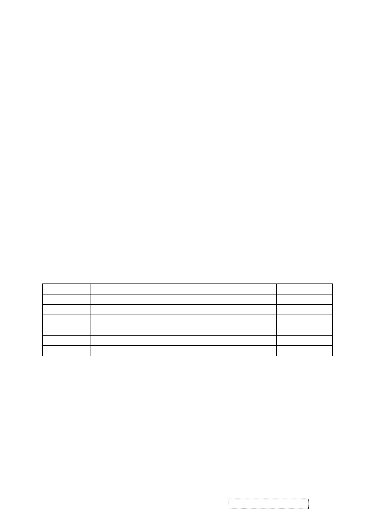
4-2 Handling and Placing Methods
Only touch the metal frame of the LCD panel or the front
cover of the monitor. Do not touch the surface of the
polarizer.
Correct Methods Incorrect Methods
Surface of the LCD panel is pressed by fingers. That may
cause “mura”.
Take out the monitor with cushions. Take out the monitor by grasping the LCD panel. That may
cause “mura”.
ViewSonic Corporation Confidential
2
-
Do Not Copy VX510
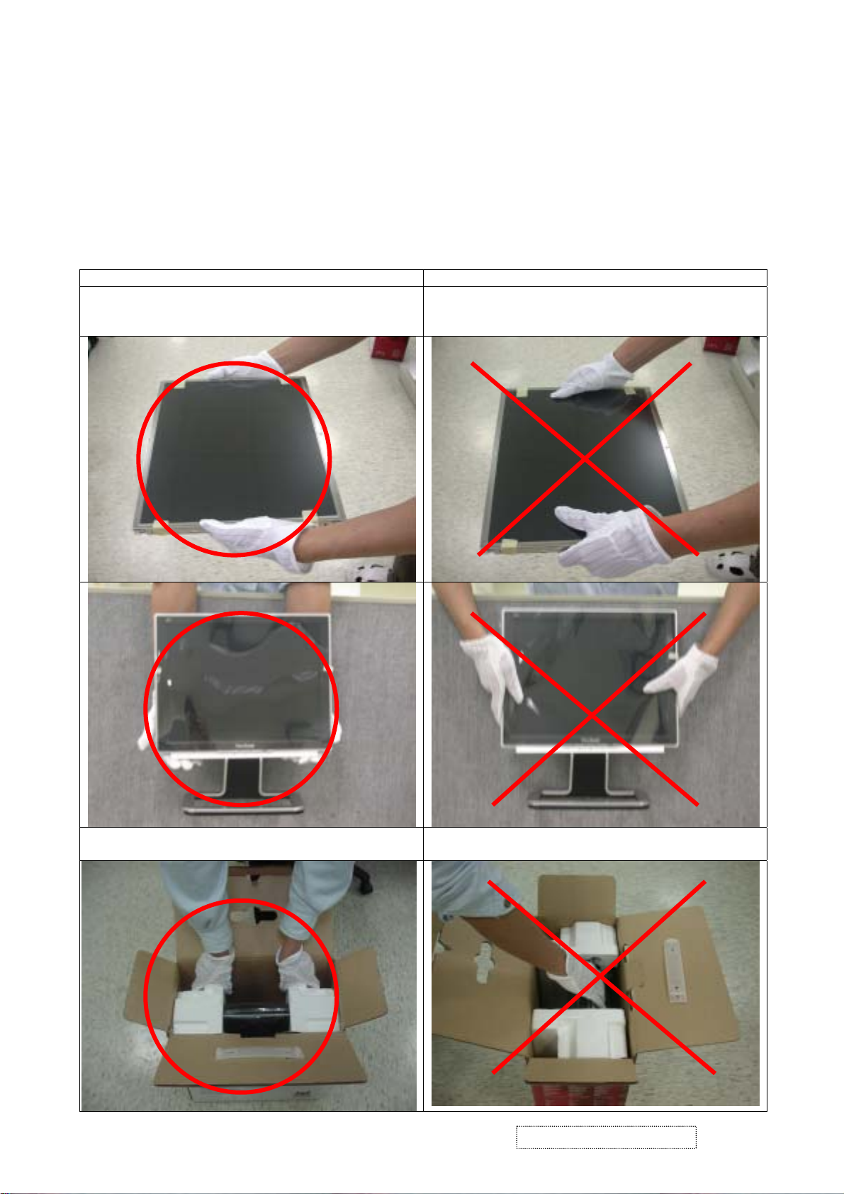
Page 6
Place the monitor on a clean and soft foam pad. Placing the monitor on foreign objects. That may scratch
the surface of the panel, or cause “mura”.
The panel is placed face-down on the lap. That may cause
“mura”.
ViewSonic Corporation Confidential
3
-
Do Not Copy VX510
Page 7
2. Specification
GENERAL REQUIREMENTS
2-1. GENERAL SPECIFICATION
Test Resolution & Frequency 1024x768 @ 60Hz
Test Image Size Full Size
Contrast and Brightness Controls
Factory Default:
Contrast = 70%, Brightness = 100%
2-2. VIDEO INTERFACE
Analog Input Connector DB-15 (Analog),
Digital Input Connector DVI-D (Digital) :N/A
Default Input Connector Defaults to the first detected input
Video Cable Connector DB-15 Pin out Compliant DDC 1/2B
Video Signals
1.Video RGB (Analog) Separate, Composite, and
Sync on Green
Video Impedance 75 Ohms (Analog)
Exclusions Not compatible with interlaced video
2-3. POWER SUPPLY
Internal Power Supply Part Number: DIAPAR002D22
Input Voltage Range 90 to 264 VAC
Input Frequency Range 47.5 to 63 Hertz
Short Circuit Protection Output can be shorted without damage
Over Current Protection 8 A typical at 5 VDC
Leakage Current 0.7mA (Max) at 254VAC / 60Hz
Efficiency 75% typical at 115VAC Full Load
Fuse Internal and not user replaceable
Power Dissipation 18.5Watts (typ),30Watts(Max.)
2-4. ELECTRICAL REQUIREMENT
Horizontal / Vertical Frequency
Horizontal Frequency 30 – 60 KHz
Vertical Refresh Rate 50 – 75Hz.
Maximum Pixel Clock 80 MHz
Primary Preset 1024x768 @ 60Hz
Timing Table
Timing -- Analog --
Item Resolution
1 640 x 350 @ 70Hz, 31.5kHz
2 640 x 400 @ 70Hz, 31.5kHz
3 640 x 480 @ 60Hz, 31.5kHz
ViewSonic Corporation Confidential
4
-
Do Not Copy VX510
Page 8
4 640 x 480 @ 67Hz, 35.0kHz
5 640 x 480 @ 72Hz, 37.9kHz
6 640 x 480 @ 75Hz, 37.5kHz
7 640 x 480 @ 85Hz, 43.27kHz
8 720 x 400 @ 70Hz, 31.5kHz
9 800 x 600 @ 56Hz, 35.1kHz
10 800 x 600 @ 60Hz, 37.9kHz
11 800 x 600 @ 75Hz, 46.9kHz
12 800 x 600 @ 72Hz, 48.1kHz
13 800 x 600 @ 85Hz, 53.7kHz
14 832 x 624 @ 75Hz, 49.7kHz
15 1024 x 768 @ 60Hz, 48.4kHz
16 1024 x 768 @ 70Hz, 56.5kHz
17 1024 x 768 @ 72Hz, 58.1kHz
18 1024 x 768 @ 75Hz, 60.0kHz
19 1024 x 768 @ 85Hz, 68.67kHz
Remark: Fv: 76Hz ~ 85Hz can be supported, not guarantee.
Changing Modes
Maximum Mode Change Blank Time for image
stability Note:
1.
Excluding Auto Adjust” time
2.
Under DOS mode (640 x 350, 720 x 400 & 640 x
Under 5 seconds (Max),
1 seconds (Typ.),for recognized timings
1-2 seconds(Typ.),for under-recognized
timings
400), there is no “Auto Adjust” feature.
3.
The monitor needs to do “Auto Adjust” the first
time a new mode is detected
2-5. LCD Panel
Panel Characteristics
Panel T ype HANNSTAR HSD150SX84-G
Type Color TFT Active Matrix XGA LCD
Active Size 304.1 (H) x 228.1 (V)
Pixel Arrangement RGB V ertical Stripe
Pixel Pitch 0.297 mm(H) x 0.297mm (V)
Glass Treatment Anti Glare (Hard coating 3H)
# of Backlights 2 CCFL edge-light (1 top / 1 bottom)
Backlight Life 40,000Hours (Typ) / 30,000 Hours (Min)
Luminance Condition:
CT = 6500K, Contrast = Max,
250 cd/m2 (Typ after 30 minute warm up)
200 cd/m2 (Min after 30 minute warm up)
Brightness = Max
Brightness Uniformity
△L5=Max 1.3 △L5 = Maximum Luminance /
Minimum Luminance
ViewSonic Corporation Confidential
5
-
Do Not Copy VX510
Page 9
Contrast Ratio 450:1 (Typ), 300:1 (Min)
Color Depth 262, 144 colors (6 bit panel)
Viewing Angle (Horizontal) 120 deg @ CR>10, 150 deg @ CR>5
Viewing Angle (Vertical) 100 deg @ CR>10, 115 deg @ CR>5
Response Time
10%-90% @ Ta=25°C
25 ms (Tr +Tf ) (Typ)
35 ms (Tr +Tf ) (Max)
2-6. MECHANICAL
Dimension (Desktop)
Width 353.69 mm
Height 387.69 mm
Depth 169.51 mm
Depth (Head only) 59.5mm
Monitor Weight 3.4 kg / 7.5 lbs
Ergonomics
20 DEGREES MINIMUM Tilt Up
5 degrees Tilt Down
Package Specifications
Width 417 mm
Height 480 mm
Depth 223 mm
Cross Weight 5.1 kg / 11.2 lbs
2-7. ENVIRONMENTAL
Environmental
Operating Temperature 0°C to +40°C
Storage Temperature -20°C to +60°C
Operating Relative Humidity 10% to 80% RH Non-Condensing
Storage Relative Humidity 10% to 90% RH Non-Condensing
Operating Altitude 0 to +3,000 meters
Storage Altitude 0 to +12,000 meters
ViewSonic Corporation Confidential
6
-
Do Not Copy VX510
Page 10

2-8 Analog EDID
Time: 08:46:29
Date: Fri Nov 14, 2003
______________________________________________________________________
______________________________________________________________________
VIEWSONIC CORPORATION
EDID Version # 1, Revision # 3
DDCTest For: ViewSonic VX510
______________________________________________________________________
______________________________________________________________________
128 BYTES OF EDID CODE:
0 1 2 3 4 5 6 7 8 9
________________________________________
0 | 00 FF FF FF FF FF FF 00 5A 63
10 | 19 64 01 01 01 01 01 0D 01 03
20 | 0E 1E 17 78 2A 71 D6 A2 56 49
30 | 96 24 13 4F 54 BF EE 00 01 01
40 | 01 01 01 01 01 01 01 01 01 01
50 | 01 01 01 01 64 19 00 40 41 00
60 | 26 30 18 88 36 00 30 E4 10 00
70 | 00 18 00 00 00 FF 00 50 33 30
80 | 30 33 30 31 30 30 30 30 31 0A
90 | 00 00 00 FD 00 32 50 1E 3C 08
100 | 00 0A 20 20 20 20 20 20 00 00
110 | 00 FC 00 56 58 35 31 30 0A 20
120 | 20 20 20 20 20 20 00 70
______________________________________________________________________
(08-09) ID Manufacturer Name = VSC
(11-10) Product ID Code = 6419
(12-15) Last 5 Digits of Serial Number = Not Used
(16) Week of Manufacture = 01
(17) Year of Manufacture = 2003
(10-17) Complete Serial Number = See Descriptor Block
(18) EDID Version Number = 1
(19) EDID Revision Number = 3
(20) VIDEO INPUT DEFINITION:
Analog Signal
0.700, 0.300 (1.000 Vp-p)
Separate Syncs, Composite Sync, Sync on Green
ViewSonic Corporation Confidential
7
-
Do Not Copy VX510
Page 11

(21) Maximum Horizontal Image Size = 300 mm
(22) Maximum Vertical Image Size = 230 mm
(23) Display Gamma = 2.20
(24) Power Management and Supported Feature(s):
Active Off/Very Low Power, Preferred Timing Mode
Display Type = R/G/B Color
(25-34) CHROMA INFO:
Red X - 0.634 Green X - 0.285 Blue X - 0.144 White X - 0.310
Red Y - 0.339 Green Y - 0.587 Blue Y - 0.075 White Y - 0.330
(35) ESTABLISHED TIMING I:
720 X 400 @ 70Hz (IBM,VGA)
640 X 480 @ 60Hz (IBM,VGA)
640 X 480 @ 67Hz (Apple,Mac II)
640 X 480 @ 72Hz (VESA)
640 X 480 @ 75Hz (VESA)
800 X 600 @ 56Hz (VESA)
800 X 600 @ 60Hz (VESA)
(36) ESTABLISHED TIMING II:
800 X 600 @ 72Hz (VESA)
800 X 600 @ 75Hz (VESA)
832 X 624 @ 75Hz (Apple,Mac II)
1024 X 768 @ 60Hz (VESA)
1024 X 768 @ 70Hz (VESA)
1024 X 768 @ 75Hz (VESA)
(37) Manufacturer's Reserved Timing:
None Specified
(38-53) Standard Timing Identification:
Not Used
Not Used
Not Used
Not Used
Not Used
Not Used
Not Used
Not Used
ViewSonic Corporation Confidential
8
-
Do Not Copy VX510
Page 12

______________________________________________________________________
(54-71) Detailed Timing / Descriptor Block 1:
1024x768 Pixel Clock: 65.00 MHz
______________________________________________________________________
Horizontal Image Size: 304 mm Vertical Image Size: 228 mm
Refreshed Mode: Non-Interlaced Normal Display - No Stereo
Horizontal:
Active Time: 1024 pixels Blanking Time: 320 pixels
Sync Offset: 24 pixels Sync Pulse Width: 136 pixels
Border: 0 pixels Frequency: 48.36 KHz
Vertical:
Active Time: 768 lines Blanking Time: 38 lines
Sync Offset: 3 lines Sync Pulse Width: 6 lines
Border: 0 lines Frequency: 60.00 Hz
Digital Separate, Horizontal Polarity (-) Vertical Polarity (-)
______________________________________________________________________
(72-89) Detailed Timing / Descriptor Block 2:
Monitor Serial Number:
P30030100001
______________________________________________________________________
(90-107) Detailed Timing / Descriptor Block 3:
Monitor Range Limits:
Min Vertical Freq - 50 Hz
Max Vertical Freq - 80 Hz
Min Horiz. Freq - 30 KHz
Max Horiz. Freq - 60 KHz
Pixel Clock - 80 MHz
Secondary GTF - Not Supported
______________________________________________________________________
(108-125) Detailed Timing / Descriptor Block 4:
Monitor Name: VX510
(126) No Extension EDID Block(s)
(127) CheckSum OK
ViewSonic Corporation Confidential
9
-
Do Not Copy VX510
Page 13
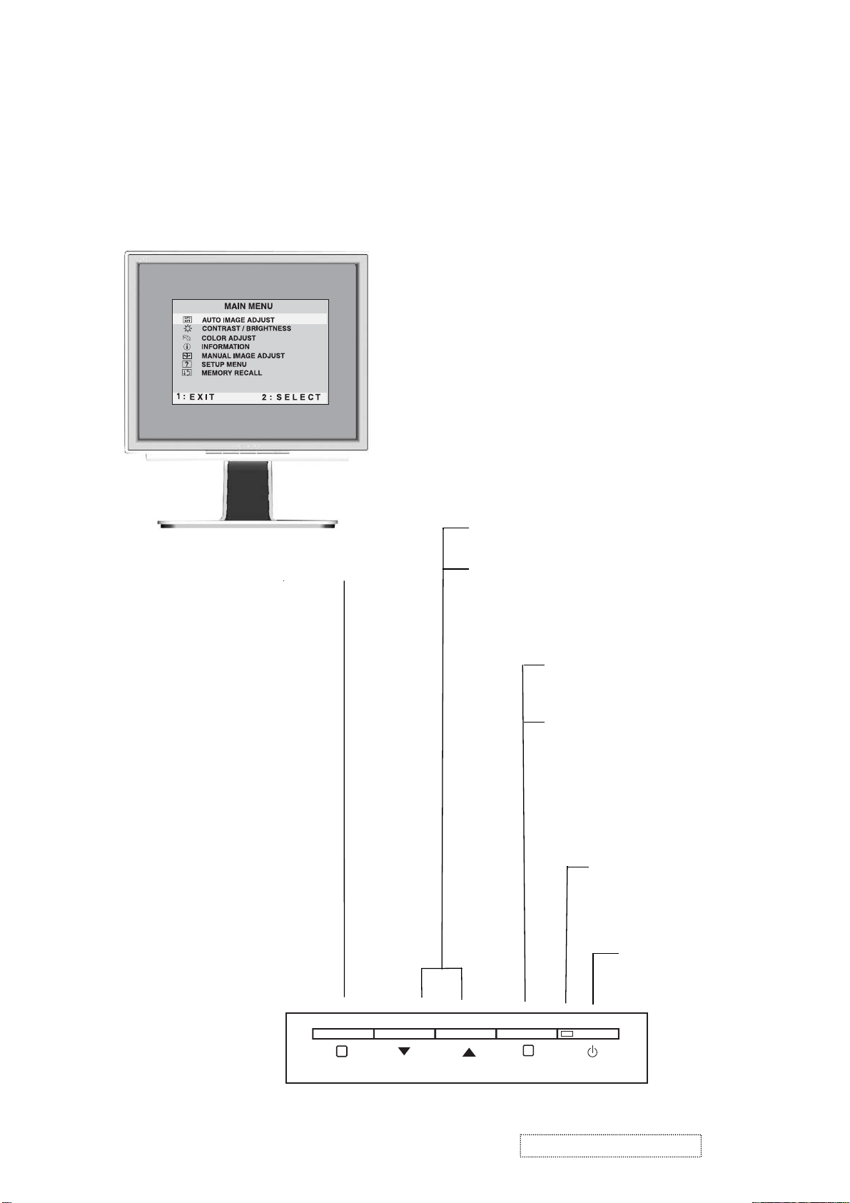
3. Front Panel Function Control Description
Adjusting the Screen Image
Use the buttons on the front control panel to display and adjust the OnView®
controls which display on the screen. The OnView controls are explained at the
top of the next page and are defined in “Main Menu Controls” on page 9.
Main Menu
With OnView controls
Front Control Panel
shown below in detail
Displays the Main Menu
or exits the control screen
and saves adjustments
Scrolls through menu options and
adjusts the displayed control.
Also a shortcut to display the
Contrast adjustment control
screen.
Displays the control
screen for the highlighted
control.
Also toggles between two
controls on some
screens.
Power light
Green = ON
Orange = Power
Saving
1
ViewSonic Corporation Confidential
10
2
Power
On/Off
-
Do Not Copy VX510
Page 14
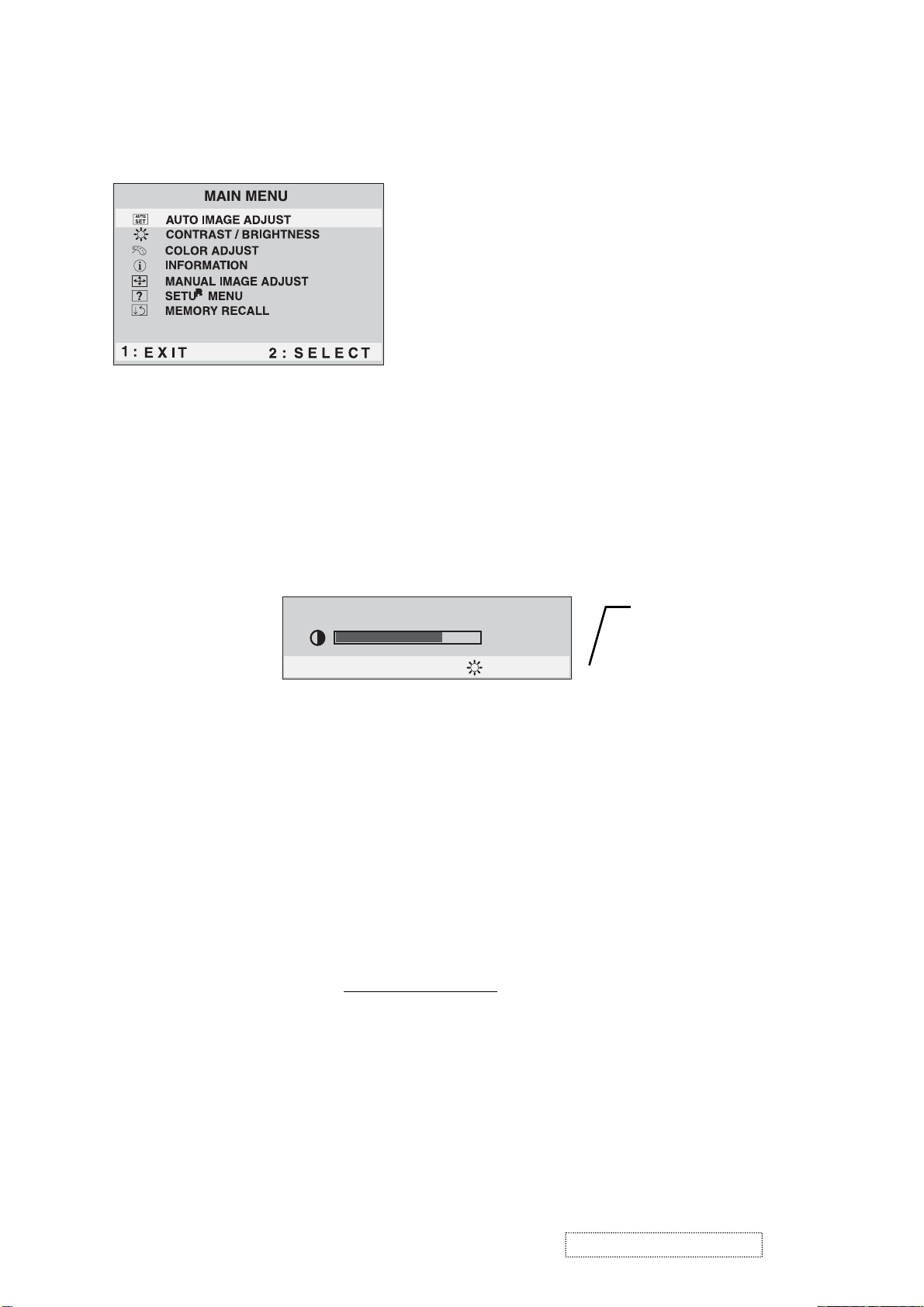
Do the following to adjust the screen image:
To display the Main Menu, press button [1].
1
NOTE:
All OnView menus and adjustment screens disappear automatically
after about 30 seconds.
To select a control you want to adjust, press ▲ or ▼ to scroll up or down the
2
Main Menu.
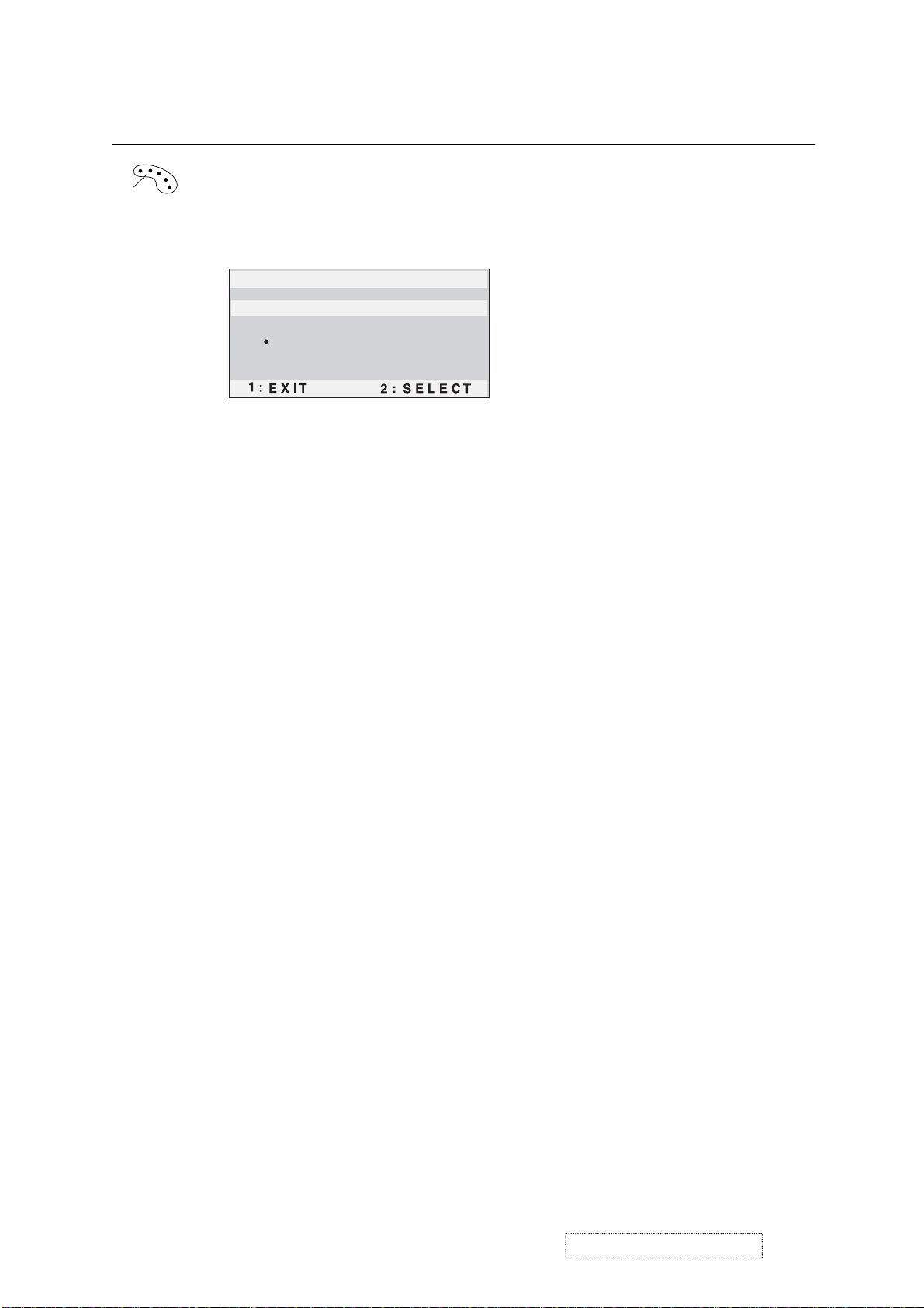
After the control is selected, press button [2]. A control screen like the one
3
shown below appears.
Contrast
1: Exit 2 : Brightness
To adjust the control, press the up ▲ or down ▼ buttons.
4
To save the adjustments and exit the menu, press button [1]
5
The following tips may help you optimize your display:
The line at the
bottom of the
screen tells you
what you can do
next: Exit or select
the Brightness
control.
.
twice
•Adjust your computer's graphic card so that it outputs a video signal 1024 x
768 @ 60 Hz to the LCD display. (Look for instructions on “changing the
refresh rate” in your graphic card's user guide.)
• If necessary, make small adjustments using H POSITION and V POSITION
until the screen image is completely visible
. (The black border around the
edge of the screen should barely touch the illuminated “active area” of the
LCD display.)
ViewSonic Corporation Confidential
11
-
Do Not Copy VX510
Page 15
Main Menu Controls
Adjust the menu items shown below by using the up ▲ and down ▼ buttons.
Control Explanation
automatically sizes, centers, and fine tunes
Auto Image Adjust
the video signal to eliminate waviness and distortion.
Press the [2] button to obtain a sharper image.
NOTE:
1. Auto Image Adjust works with most common video cards.
If this function does not work on your LCD display, then
lower the video refresh rate to 60 Hz and set the resolution
to its
2. The Auto Image Adjust and most Manual Image Adjust
pre-set value.
functions are not available for DVI input.
Contrast
adjusts the difference between the image background
(black level) and the foreground (white level).
Brightness
adjusts background black level of the screen image.
ViewSonic Corporation Confidential
12
-
Do Not Copy VX510
Page 16
Control Explanation
Color Adjust
color temperatures and
provides several color adjustment modes: preset
RGB
which allows you to adjust red (R),
green (G), and blue (B) separately. The factory setting for this
product is 6500K (6500 Kelvin).
Color Adjust
SRGB
9300K
6500K
5400K
User Color
sRGB
— sRGB is quickly becoming the industry standard for color
management, with support being included in many of the latest
applications. Enabling this setting allows the LCD display to
more accurately display colors the way they were originally
intended. Enabling the sRGB setting will cause the Contrast and
Brightness adjustments to be disabled.
9300K
— Adds blue to the screen image for cooler white (used
in most office settings with fluorescent lighting).
6500K
— Adds red to the screen image for warmer white and
richer red.
5400K
User Color
and blue (B)
1
2
Important
— Adds green to the screen image for a darker color.
— Individual adjustments for red (R), green (G),
.
To select color (R, G or B) press button [2].
To adjust selected color, press ▲ or ▼.
: If you select RECALL from the Main Menu when
the product is set to a Preset Timing Mode, colors return to the
6500K factory preset.
ViewSonic Corporation Confidential
13
-
Do Not Copy VX510
Page 17

Control Explanation
Information
displays the timing mode (video signal input)
coming from the graphics card in your computer. See your
graphic card’s user guide for instructions on changing the
resolution and refresh rate (vertical frequency).
NOTE:
VESA 1024 x 768 @ 60 Hz (recommended) means
that the resolution is 1024 x 768 and the refresh rate is 60
Hertz.
Information
H. Frequency: 31.47 KHz
V. Frequency: 31.47 Hz
Pixel Clock: 24.80 MHz
Resolution: 640 x 480
Model No. :
Serial No. :
1: Exit
Manual Image Adjust
www.viewsonic.com
displays the Manual Image Adjust menu.
Manual Image Adjust
H . / V . Position
H . Size
Fine Tune
Sharpness
1: Exit 2 : Select
The
Manual Image Adjust
Horizontal Position
Vertical Position
Horizontal Size
sharpens focus by aligning the illuminated text and/
Fine Tune
moves the screen image left or right.
moves the screen image up or down.
adjusts the width of the screen image.
or graphic characters.
adjusts the clarity and focus of the screen image.
Sharpness
controls are explained below:
ViewSonic Corporation Confidential
14
-
Do Not Copy VX510
Page 18

Control Explanation
Setup Menu
Language Select
Resolution Notice
OSD Position
OSD Time Out
OSD Background
1: Exit
The
Setup Menu
Language
displays the menu shown below.
Setup Menu
controls are explained below:
allows you to choose the language used in the menus
and control screens.
Resolution Notice
below.
RESOLUTION NOTICE
For best picture quality, change
the resolution to 1024 x 768
displays the Resolution Notice menu shown
Press "1" to clear message
Press "2" to disable message
1 : Exit
Resolution Notice
OSD Position
advises the optimal resolution to use.
allows you to move the on-screen display menus
and control screens.
sets the length of time an on-screen display
OSD Timeout
screen is displayed. For example, with a “15 second” setting, if
a control is not pushed within 15 seconds, the display screen
disappears.
OSD Background
allows you to turn the On-Screen-Display
background on or off.
Memory Recall
returns adjustments to the original factory
settings if the display is operating in a factory Preset Timing
Mode listed in this user guide.
Exception:
This control does not affect changes made with the
User Color control, Language and Power Lock setting.
ViewSonic Corporation Confidential
15
-
Do Not Copy VX510
Page 19

4. Circuit Description
MCU
The Winbond W78E65 is an 8-bit microcontroller which has in-system programmable
FLASH EPROM for firmware updating. The instruction set of the W78E65 is fully
compatible with the standard 8052. The W78E65 contains a 64K bytes of main
FLASH EPROM to be updated by the loader program located at the 4KB auxiliary
FLASH EPROM; four 8-bit ib-directional and bit-addressable I/O ports; three 16-bit
timer/counters; a serial port. The W78E65 allows user to modify firmware by using
ISP function. Once the code is confirmed, the user can protect the code for security.
RTD2011B
The RTD2011B is a graphic processing IC for Liquid Crystal Display (LCD) monitors, It support up to
110MHz (XGA@85Hz). On-chip functions include a 8-bit triple-channel 110MHz ADC, PLL, 8-bit, a
high quality zoom scaling engine, Sharpness/Smooth filter enhancement, digital color processor,
embedded on-screen display (OSD) controller support multi-language. In output interface, it can
support TTL, Reduced Swing Differential Signaling (RSDS) data bus type 1~3.and programmable
TCON function.
Video
Decoder
DDC
VS
HS
R/G/B
1C
8
D
RTD2011B
Flat Panel Display
IIC
24.576MHz
TCON
48D
5C
48D
48D
5C
5C
LCD Panel
Row/Column
Driver
TTL Signal
LCD Panel
RSDS Signal
LCD Panel
MCU
ViewSonic Corporation Confidential
16
-
Do Not Copy VX510
Page 20

5. Adjusting Procedure
1. Function Test
1.1 Product
- 15” LCD monitor
1.2 Test Equipment
-Color Video Signal & Pattern (or PC with XGA resolution)
1.3 Test Condition
Before function test and alignment, each LCD monitor should be warmed up for
at least 30 minutes with the following conditions:
(a) In room temperature,
(b) With full-white screen, RGB, and Black
(c) With cycled display modes,
640*480 (H=43.27kHz, V=85Hz)
800*600 (H=53.7kHz, V=85Hz)
1024*768 (H=68.67, V=85Hz)
1.4 Test Display Modes & Pattern
1.4.1 Compatible Modes
1. 640 x 350@ 70Hz, 31.5kHz 12. 800 x 600@ 72Hz, 48.1kHz
2. 640 x 400@ 70Hz, 31.5kHz
3
. 640 x 480@ 60Hz, 31.5kHz
4
. 640 x 480@ 67Hz, 35.0kHz
5. 640 x 480@ 72Hz, 37.9kHz 16. 1024 x 768@ 70Hz, 56.5kHz
6. 640 x 480@ 75Hz, 37.5kHz
7
. 640 x 480@ 85Hz, 43.27kHz
8
. 720 x 400@ 70Hz, 31.5kHz
9
. 800 x 600@ 56Hz, 35.1kHz
10. 800 x 600@ 60Hz, 37.9kHz
11. 800 x 600@ 75Hz, 46.9kHz
13. 800 x 600@ 85Hz, 53.7 kHz
14. 832 x 624@ 75Hz, 49.7kHz
15. 1024 x 768@ 60Hz, 48.4kHz
17. 1024 x 768@ 72Hz, 58.1kHz
18. 1024 x 768@ 75Hz, 60.0kHz
19. 1024 x 768@ 85Hz, 68.67kHz
ViewSonic Corporation Confidential
17
-
Do Not Copy VX510
Page 21

1.4.2 Function Test Display Pattern
Item Test Content Pattern Specification Remark
1 Frequency & Tracking Fine Line Moire Eliminate visual wavy noise. Figure1
2 Contrast/Brightness 16Gray Scale 16 gray levels should be
distinguishable.
3 Boundary Horizontal & Vertical
Thickness
Horizontal and Vertical position
Of video should be adjustable to
Be within the screen frame.
4 RGB Color Performance RGB Color Intensities Contrast of each R,G,B,color
Should be normal.
5 Screen Uniformity & Flicker Full White Should be compliant with the spec. Figure7
6 Dead Pixel/Line White Screen & Dark Screen The numbers of dead pixels should
Be compliant with the spec.
7 White Balance White & Black Pattern The screen must have the pure white
And black pattern, no other color.
Figure2
Figure3
Figure4,5,6
Figure7,8
Figure9
ViewSonic Corporation Confidential
18
-
Do Not Copy VX510
Page 22

ViewSonic Corporation Confidential
19
-
Do Not Copy VX510
Page 23

1.5 Function Test and Alignment Procedure
1.5.1 All Modes Reset
You should do “Memory Recall’’on Main Menu first.This action will allow you to
erase all end-user’s settings and restore the factory defaults.
1.5.2 Auto lmage Adjust
Please select and enter“Auto Image Adjust’’function on Main menu to see if it workable.
The“Auto Image Adjust’’function is aimed to offer a better screen quality by built-
In ASIC . For optimum screen quality, the user has to adj
ust each function manually.
1.5.3 Firmware
Test Pattern:Burn In Mode
-Mark sure the F/W is the latest version.
1.5.4 DDC
Test Pattern:EDID program
-Make sure it can pass test program.
1.5.5 Fine Tune and Sharpness
Test Signal:1024*768@60Hz
Test Pattern:Line Moire Pattern
-Check and see if the i
mage has noise and focus performs well.Eliminate visual line bar.
-If not,readjust by the following steps:
(a) Select and enter“Fine Tune’’function on“Manual Image Adjuet’’to adjust the
image to adjust the image to eliminate visual wavy noise.
(b) Then, selsct and enter“Sharpness’’fnuction to adjust the clarity and focus.
1.5.6 Boundary
Test Signal:1024*768@60Hz
Test Pattren:Horizontal & Vertical Line Thickness Pattern
-Check and see if the image boundary is within screen frame.
-If not, readjust by the following steps:
(a) Select and enter “Manual Image Adjuet’’ function on OSD Main Meun.
(b) Then, select and enter“Horizontal Size’’or“Horizontal/Vertical Position’’
function to adjust the video boundty to be full scanned and within screen frame.
ViewSonic Corporation Confidential
20
-
Do Not Copy VX510
Page 24

1.5.7 White Balance
Test Signal:640*480@60Hz
Test Pattern:White and Black Pattern
1.5.8 RG BColors Contrast
Test Signal:1024*768@60Hz
Test Pattern:R,G,B,Color Intensities Pattern and 16 Gray Scale Pattern
-Check and see if each color is normal and distinguishable.
-If not,please return the unit to repair area.
1.5.9 Screen Uniformity and Flicker
Test Signal:1024*768@60Hz
Test pattern:Full White Pattern
-Check and see if it is in normal condition.
1.5.10 Dead Pixel and Linegnal
Test Signal:1024*768@60Hz
Test Pattern: Dark and White Screen Pattern
-Check and see if there are dead pixels on LCD panel with shadow gauge and filter film.
-The total numbers and distance of dead pixels should be compliant with the spec.
1.5.11 Mura
Test Pattern:White,GRB,Black,&Gary
T est Tool:5%ND Filter.
1.5.12 Check for Secondary Display Modes
Test Signal:
Analog:640*350@70Hz;640*480@60/67/72/75/85Hz
720*400@70Hz;800*600@56/60/72/75/85Hz
832*624@75Hz,1024*768@60/70/72/75/85Hz
-Normally when the primary mode1024*768@60Hz is well adjusted and compliant
with the specification,the secondary modes will also be compliant with the spec.But
we still have to check with the general test pattern to make sure every secondary is
compliant with the specification.
1.5.13 All Modes Reset
After final QC step,we have to erase all saved changes again and restore the factory
defaults.You should do“All mode Reset’’again.
1.5.14 Power Off Monitor
Turn off the monitor by pressing“Power’’ button.
ViewSonic Corporation Confidential
21
-
Do Not Copy VX510
Page 25

2 Adjusting Procedure - Firmware Upgrade Procedure
When you receive the returned monitor, please check whether the firmware version is
the latest. If not, please do the following procedures to upgrade it to the latest version.
2-1 Equipment Needed
-VX510 Monitor
-Fixture for Firmware upgrade
-Power adapter *1 for Fixture
-VGA Cable *2
-PC (Personal Computer)
-Com port Cable *1
-Firmware Upgrade program
-One additional monitor for checking the program execution
VX510 Fixture
VGA Cable PC
ViewSonic Corporation Confidential
22
-
Do Not Copy VX510
Page 26

Com port Cable Power Adapter for Fixture
2-2 Setup Procedure
2.2.1 Connect P3 of fixture with Com port of PC by Com port Cable.
2.2.2 Connect P1 of fixture with VX510 Monitor by VAG Cable.
2.2.3 Connect P2 of fixture with PC VGA output by VAG Cable.
2.2.4 Plug Power Adapter to fixture.
2.2.5 Connect Power Card to VX510 Monitor.
2.2.6 Connect PC to the additional monitor.
JP1:to
Power
Adapter
ViewSonic Corporation Confidential
23
-
Do Not Copy VX510
Page 27

2.2.7 Run “RTDTOOL”file
2.2.8 Choose ”Winboad 62/65B” and then push “SET” button
ViewSonic Corporation Confidential
24
-
Do Not Copy VX510
Page 28
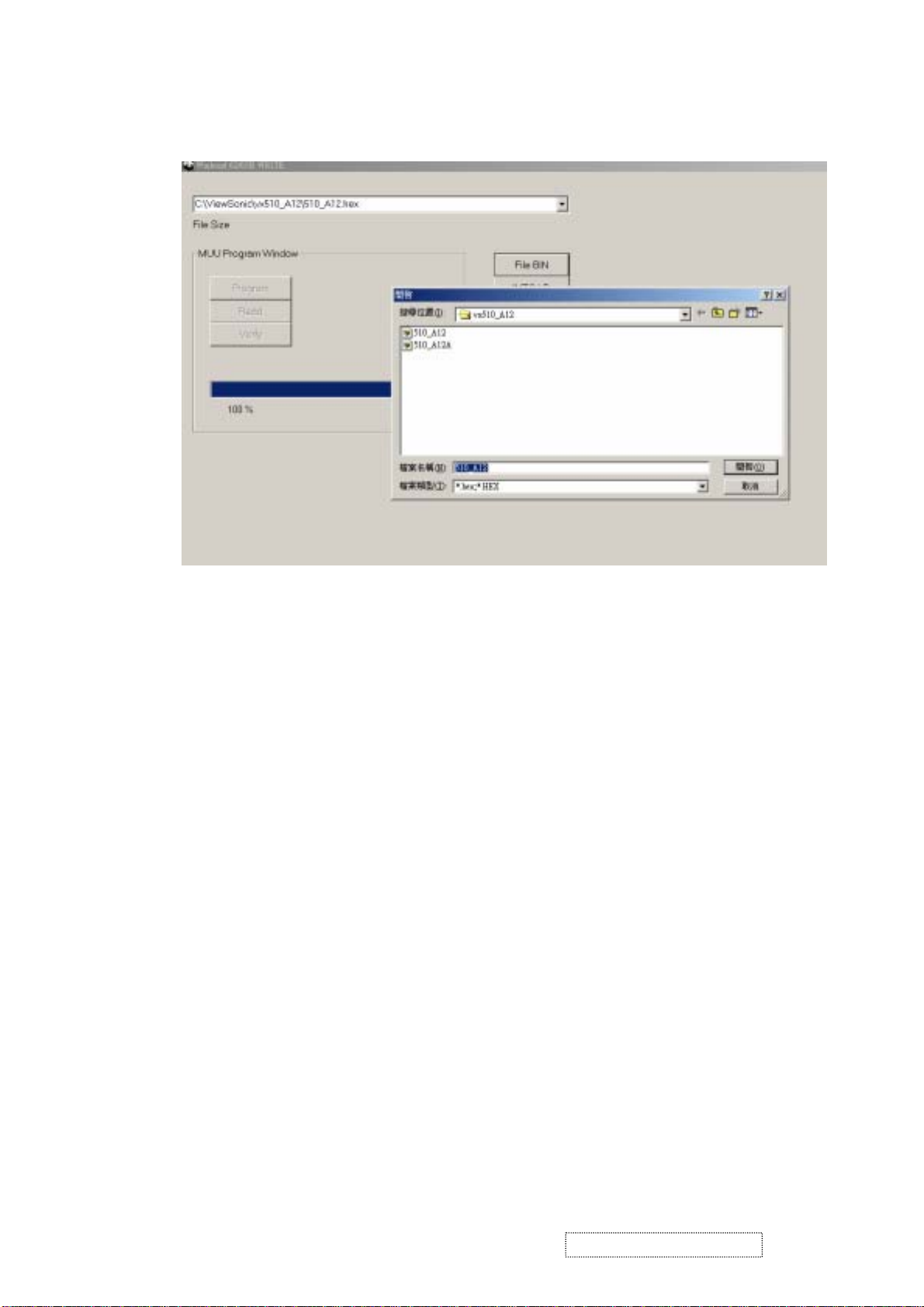
2.2.9 Push “File Bin” button and then choose the latest firmware that we want to upgrade
ViewSonic Corporation Confidential
25
-
Do Not Copy VX510
Page 29

Step 1. Let VX510 enter ISP mode
1.1 Press Menu key (keep on) than plug power to VX510 monitor after 2-3 second,
and release away Menu key.
1.2 Press “Connect ” then enter the ISP mode.(software will show “Link success¨
if we enter the ISP mode successful)
ViewSonic Corporation Confidential
26
-
Do Not Copy VX510
Page 30

Step 2 Push “Program” button and start to enter upgrade process
Step 3. Upgrade successful
ViewSonic Corporation Confidential
27
-
Do Not Copy VX510
Page 31

S
6. Trouble Shooting Flow Chart
This chapter provides technicians and people who have an electronic background a primary description about
maintaining the product. Moreover, you can get the appropriate operation to solve some complicated problems
of component repairing and professional problems.
1. Equipment Needed
- VX510 Monitor
- Philips Screw Driver # 101 and # 107
- Electronic Hex Nut M5 mm
- PC with XGA resolution
2. Main Procedure
tart
Power-on
Power LED OK ?
Is Display
Performance OK?
Is Function
adjustment OK?
Yes
Yes
Yes
No
No
No
A. Power Circuit
Troubleshooting
B. Performance
Troubleshooting
C. Function
Troubleshooting
End
ViewSonic Corporation Confidential
28
-
Do Not Copy VX510
Page 32

2.1 A. Power Circuit Troubleshooting
Start
Start
Change
Power
Board
No
Yes
End
2.2 B. Performance Troubleshooting
Yes Yes
Is screen Black ?
No No
Change
Video Board
Change
Power
Board
Change
Video
Board
Yes
Change
LCD
Panel
No
Is screen White ?
No
Abnormal Color ?
No
1
Yes Yes Yes
Replug or
Change
FFC cable
Change
Video
Board
No No
Yes Yes
Change
Video
Board
Change
LCD
Panel
No
Change
LCD
Panel
ViewSonic Corporation Confidential
29
-
Do Not Copy VX510
Page 33

1
Yes
Is Lcd line defective ?
No
No
Is screen scrolling ?
No
Is screen flickering ?
Mura ?
Yes
Yes
No
No
Change Lcd Panel
Change Lcd Panel
Change
VGA Cable
Change
Video Board
Yes
Change
Video Board
Yes Yes
Change
Lcd Panel
No
Bad uniformity ?
No
Have line bar or
noise ?
No
Ghost image ?
No
End
Yes Yes
Change
Power Board
No
Yes Yes
Change
Power Board
No
Yes Yes Yes
Notice
1
Adjust
sharpness or
auto
No No No
Change
Lcd Panel
Change
Video Board
Notice
2
Yes
Change
Video
Board
ViewSonic Corporation Confidential
30
-
Do Not Copy VX510
Page 34

Notice:
1. Make sure VGA cable connected to PC directly, not via anything like “data transfer “ or “ distribution".
After this action if ghost image disappears , go to “ yes”; else go to “ no”.
2. Check the compatibility on the computer. If it is compatibility problem, feedback the information to
ViewSonic ; else , go to “ no”
2.3 C. Function Troubleshooting
Start
No
Change
Change Button Board
Video Board
Yes
End
ViewSonic Corporation Confidential
31
-
Do Not Copy VX510
Page 35

7. Recommended Spare Parts List
VX510 Recommended Spare Parts List
Item VS P/N Arima P/N Description Q'ty Lead Time
N/A K0015001000000 BASIC UNIT VX510 1
1 M-SCW-0824-0856 700473300-1000 SCREW TAPPING 3.0*10L P-HEAD P-TITE-ZN/B 6 10 days
N/A K0015012000000 LCD PANEL ASSY VX510 1
2 B-CB-0206-0189 40-VF000T-C000 PWA BUTTON BOARD VF000 1 2 weeks
3 C-FP-0301-0997 K0015028000000 BEZEL SUB-ASSY VX510 1 4 weeks
N/A K0015028000001 CHASSIS SUB-ASSY VX510 1
4 M-BK-0805-0082 K5120000000003 CHASSIS FRAME VX510 1 3 weeks
5 M-MS-0808-9478 K5120000000010 SHIELDING VX510 1 3 weeks
6 M-SCW-0824-0857 703014250-2500 SCREW PH M2.5*0.45 L4(DIA=4.5 T=0.8) 6 10 days
7 M-SCW-0824-0858 702114300-0600 SCREW MACHINE M3*6L B HEAD NI 9 10 days
8 M-SCW-0824-0859 700114303-0800 SCREW M3*8L P-HEAD W/SP+FLATE WASHER NI 1 10 days
9 M-LCD-0826-0225 37-125150-4900 LCD TFT 15.0" XGA HSD150SX84-G HANNSTAR 1 8 weeks
10 B-VB-0202-0355 40-VF0009-C000 PWA VIDEO BOARD VF000 1 2 weeks
11 B-PS-0204-0072 83-110119-0000 AC POWER SUPPLY&DC-AC INVERTER W/VF000 1 45 days
12 M-MS-0808-9479 32-000080-0000 CORE PL2508IG 25.5*15*4.5mm FOR VF000 2 45 days
13 M-FC-0809-0816 K5052000000000 CABLE ASSY FFC (40*56) VX510 2 30 days
14 M-MS-0808-9480 77X014006-4800 STANDOFF#4-40 H4.8(L7.0 THREAD)HEXA-4.75 2 10 days
15 TBD K5120000000012 INSULATOR FOR SHIELDING VX510 2 2 weeks
16 TBD 700114406-0800 MACHINE SCREW M4*L8 PH W/EX TOOTH WASHE 1 10 days
17 TBD K5310000000008 LABEL FOR WARNING-HIGH VOLTAGEL VX510 1 2 weeks
18 TBD K5110000000015 AL FOIL FOR INVERTER WIRE OF PANEL VX510 1 TBD
19 M-FC-0809-0817 21-5H0001-0000 CABLE ASSY HARNESS 8P*8P 140mm W/VF000 1 30 days
20 M-SCW-0824-0860 702472300-0800 TAPPING SCREW 3.0*8L B HEAD P TITE Zn YL 10 10 days
N/A K0015013000000 REAR COVER ASSY VX510 1
21 M-SCW-0824-0861 700374400-1200 SCREW TAPPING 4.0*12L P-HEAD B-TITE N 2 10 days
22 M-MS-0808-9481 K5110000000014 RUBBER WALL MOUNT PLUG(BLACK) VX510 4 2 weeks
23 M-MS-0808-9482 K5120000000004 PLATE HINGE VX510 1 3 weeks
24 M-MS-0808-9483 K5120000000006 PLATE WALL MOUNT VX510 4 3 weeks
25 M-WR-0828-0757 21-5W0000-0000 WIRE 1015 #18 AWG 100mm DA7835 GR/YEL 1 45days
26 C-BC-0302-0600 K0015028000002 COVER BACK SUB-ASSY VX510 1 4 weeks
N/A K0015013000001 STAND ASSY VX510 1
27 M-SCW-0824-0862 700114401-0800 SCREW MACHINE M4*8L P-HEAD W/SP WASHER 4 10 days
28 M-CV-0830-0324 K5110000000005 BASE-TOP (SILVER) VX510 1 4 weeks
29 M-CV-0830-0325 K5110000000006 BASE BOTTOM (BLACK) VX510 1 4 weeks
30 M-CV-0830-0326 K5110000000009 COVER FRONT BASE(BLACK) VX510 1 4 weeks
31 M-MS-0808-9484 K5110000000011 CLAMP FOR AC D-SUB CABLE(PIN GOOD)CKK 05 2 4 weeks
32 M-MS-0808-9485 K5110000000013 RUBBER FOOT(GRAY)VX510 6 2 weeks
33 M-BK-0805-0083 K5120000000001 BRACKET L VX510 1 3 weeks
34 M-BK-0805-0084 K5120000000002 BRACKET R VX510 1 3 weeks
35 M-MS-0808-9486 K5120000000007 PLATE WEIGHT L(172.13) VX510 1 3 weeks
36 M-MS-0808-9487 K5120000000009 PLATE WEIGHT S(78.3) VX510 2 3 weeks
37 M-MS-0808-9488 K5120000000011 HINGE VX510 1 3 weeks
38 TBD K5120000000013 PORON FOR PLATE WEIGHT VX510 2 2 weeks
39 M-SCW-0824-0862 700114401-0800 SCREW MACHINE M4*8L P-HEAD W/SP WASHER 2 10 days
40 M-CV-0830-0327 K5110000000007 COVER FOR AC D-SUB (BLACK) VX510 1 4 weeks
41 M-CV-0830-0328 K5110000000008 COVER FOR BASE CABLE (BLACK) VX510 1 4 weeks
N/A K0015014000003 PACKING KIT VSA/VSAP (M) VX510 1
42 A-VC-0101-0378 21-5D0000-0000 CABLE ASSY D-SUB 15P H/D 9C W/CORE 1 10 weeks
43 A-PC-0106-0328 21-900212-0000 AC POWER CORD USA 3C BLACK W/VF000 1 30 days
44 M-MS-0808-9496 K0015020000000 VIEWSONIC QSG W/CD W/PE BAG VX510 1 3 weeks
45 M-LB-0813-1005 K5310000000001 SMALL LABEL 40*25 VX510 1 2 weeks
46 M-LB-0813-1006 K5310000000002 ID LABEL 108*48.9 VX510 1 2 weeks
47 M-LB-0813-1007 K5310000000003 UPC LABEL 76.2*76.2 VX510 1 2 weeks
48 M-LB-0813-1008 K5310000000004 HI-POT PASS LABEL VX510 1 2 weeks
49 M-LB-0813-1009 K5320000000001 NAME PLATE VIEWSONIC FRONT(E015-016-1)VX 1 10 days
50 M-LB-0813-1010 K5320000000002 LOGO BIRD FRONT(E015 004)AL7.9H VX510 1 10 days
51 M-LB-0813-1011 K5320000000003 LOGO VIEWSONIC ELLIPTIC BACK E015-017 VX 1 10 days
52 P-BX-0601-0975 K5510000000001 GIFT BOX VX510 1 10 days
53 P-FM-0602-0878 K5550000000001 POLY FOAM L VX510 1 2 weeks
54 P-FM-0602-0879 K5550000000002 POLY FOAM R VX510 1 2 weeks
55 M-MS-0808-9489 K5551000000001 PE BAG W420*H550 VX510 1 10 days
56 TBD AAF155500025J0 PLASTIC HANDLE FOR SOTEC A0561 1 3 weeks
57 P-BX-0601-0976 K5510000000002 PLAIN GIFT BOX VX510 1 10 days
ViewSonic Corporation Confidential
32
-
Do Not Copy VX510
Page 36

VX510 BOM
VX510-1 BOM
Item ViewSonic P/N Reference P/N Description Q'ty
1 #N/A K0015001000000 BASIC UNIT VX510 1
2 M-SCW-0824-0856 700473300-1000 SCREW TAPPING 3.0*10L P-HEAD P-TITE-ZN/B 6
3 #N/A K0015012000000 LCD PANEL ASSY VX510 1
4 B-CB-0206-0195 40-VF000T-B100 PWA BUTTON BOARD VF000 1
5 #N/A 36-020071-0000 TACT SW TC-0102X 160gf DIP 5
6 #N/A 37-018365-1300 LED 319YGW-C Y/G ROUND 2.9mm DIP 1
7 #N/A 39-316008-0600 CONN PLUG R/A 8P P:2mm 86808-0800 DIP 1
8 #N/A 41-VF000T-B000 PCB BUTTON BOARD VF000 Rev:B 1
9 C-FP-0301-0997 K0015028000000 BEZEL SUB-ASSY VX510 1
10 C-FP-0301-1036 K5110000000001 BEZEL (BLACK) VX510 1
11 M-CV-0830-2570 K5110000000003 COVER MIDDLE (SILVER ) VX510 1
12 PL-BT-0706-0175 K5110000000004 BUTTON (SILVER) VX510 1
13 M-MS-0808-9742 K5110000000010 LENS FOR POWER LED (CLEAR) VX510 1
14 #N/A 702374300-0800 SCREW TAPPING 3.0*8L B-HEAD B-TITE NI 8
15 #N/A K0015028000001 CHASSIS SUB-ASSY VX510 1
16 M-MS-0808-9479 32-000080-0000 CORE PL2508IG 25.5*15*4.5mm FOR VF000 2
17 M-BK-0805-0082 K5120000000003 CHASSIS FRAME VX510 1
18 M-MS-0808-9478 K5120000000010 SHIELDING VX510 1
19 M-SCW-0824-0857 703014250-2500 SCREW PH M2.5*0.45 L4(DIA=4.5 T=0.8) 6
20 M-SCW-0824-0858 702114300-0600 SCREW MACHINE M3*6L B HEAD NI 9
21 M-SCW-0824-0859 700114303-0800 SCREW M3*8L P-HEAD W/SP+FLATE WASHER NI 1
22 M-LCD-0826-0225 37-125150-4900 LCD TFT 15.0" XGA HSD150SX84-G HANNSTAR 1
23 #N/A 40-VF0009-A100 PWA VIDEO BOARD VF000 1
24 #N/A 10-002011-9700 IC RTD2011B FLAT LCD CONTROLLER QFP-208 1
25 #N/A 10-007865-9500 IC W78E65P-24/40 8BIT uCONTROLLER PLCC44 1
26 #N/A 12-107414-8300 IC 74LVC14AD SO-14 1
27 #N/A 14-63855L-7000 IC 24LC21AT/SN 1K(128*8) 2.5V SOP-8 1
28 #N/A 14-678553-7000 IC M24C16-WMN6T 16K(2K*8) 2.5V SOP-8 1
29 #N/A 18-001117-7700 IC LM1117MPX-3.3 REGULATOR SOT-223-3 2
30 #N/A 18-003904-9000 TR NPN MMBT3904 40V 200mA 225mW SOT-23 5
31 #N/A 18-008815-7700 IC AME8815BEGT250 1.5A REGULATOR SOT-223 1
32 #N/A 18-109435-9900 MOSFET P-CH CEM9435A 30V 5.3A SOP-8 1
33 #N/A 20-000042-8700 DIODE ZENER UDZS5.6B 5.6V 200mW SMD 6
34 #N/A 20-090099-8800 DIODE ARRAY BAV99 SWITCHING SOT-23 3
35 #N/A 20-100202-0200 DIODE SW TWIN DAN202U UMT 1.25*2.0 1
36 #N/A 30-000006-9500 RES CHIP 0ohm J 0603 7
37 #N/A 30-001016-9500 RES CHIP 100ohm J 0603 27
38 #N/A 30-001026-9500 RES CHIP 1Kohm J 0603 3
39 #N/A 30-001036-9500 RES CHIP 10Kohm J 0603 3
40 #N/A 30-001056-9500 RES CHIP 1Mohm J 0603 1
41 #N/A 30-002016-9500 RES CHIP 200ohm J 0603 1
42 #N/A 30-002226-9500 RES CHIP 2.2Kohm J 0603 2
43 #N/A 30-004726-9500 RES CHIP 4.7Kohm J 0603 18
44 #N/A 30-006816-9000 RES CHIP 680ohm J 0805 2
45 #N/A 30-008226-9500 RES CHIP 8.2Kohm J 0603 1
46 #N/A 30-175016-9500 RES 75 +-5% 1/16W 0603 3
47 #N/A 30-202026-9500 RES CHIP 1/16W 2Kohm 5% 0603 2
48 #N/A 30-202206-9500 RES CHIP 1/16W 22ohm 5% 0603 16
49 #N/A 30-202216-9500 RES CHIP 1/16W 220ohm 5% 0603 200ppm 3
50 #N/A 30-362204-8700 RES ARRAY CHIP 22ohm*4 J 1206 9
51 #N/A 31-103306-9500 CAP CERA CHIP 50V 33pF 5% X7R 0603 2
52 #N/A 31-132268-1200 CAP ELEC 16V 22uF M S5016M0022S5D DIP 4
53 #N/A 31-164737-9500 CAP CERA CHIP 16V 47nF K X7R 0603 3
54 #N/A 31-201049-9500 CAP CERA CHIP 50V 100nF Z Y5V 0603 43
55 #N/A 31-231068-1200 CAP ELEC CHIP 16V 10uF M 16CV10BS 1
56 #N/A 31-301003-9500 CAP CERA CHIP 50V 10pF D NPO 0603 TDK 5
57 #N/A 31-302006-9500 CAP CERA CHIP 50V 20pF 5% NPO 0603 1
58 #N/A 31-302206-9500 CAP CERA CHIP C0G 50V 220J 0603(22PF) 16
59 #N/A 31-364704-8300 CAP ARRAY CHIP 47pF*4 J NPO 1206 9
60 #N/A 31-481059-9500 CAP CERA CHIP 10V 1uF +80%/-20% Y5V 0603 3
61 #N/A 31-942278-1300 CAP ELEC 25V 220uF 20% 105'C 8*11mm L.I 1
62 #N/A 31-A31078-1200 CAP ELEC 16V 100uF M 6*5mm DIP W/CUT 3
63 #N/A 32-700603-1900 BEAD CHIP 19ohm 0.5A SBK160808T-190Y-S 3
64 #N/A 32-731206-6000 BEAD CHIP 60ohm 0.5A SBY321611T-600Y-S 7
65 #N/A 35-240002-4000 X'TAL 24MHz 20pF 20ppm 49S 6B24000377 1
66 #N/A 35-245762-4010 X'TAL 24.576MHz 6B24500292 W/CUT 3.4mm 1
ViewSonic Corporation Confidential
33
-
Do Not Copy VX510
Page 37

VX510-1 BOM
Item ViewSonic P/N Reference P/N Description Q'ty
67 #N/A 38-020044-0300 SOCKET PLCC 44PIN SMD CS224410000 1
68 #N/A 38-418015-3J00 CONN D-SUB 15P R/A H/D A02003-11 DIP 1
69 #N/A 38-527040-0700 CONN FPC R/A 40P P:0.5mm BOT 88532-4003 2
70 #N/A 39-316008-0600 CONN PLUG R/A 8P P:2mm 86808-0800 DIP 2
71 #N/A 41-VF0009-A000 PCB VIDEO BOARD VF000 1
72 B-PS-0204-0072 83-110119-0000 AC POWER SUPPLY&DC-AC INVERTER W/VF000 1
73 M-FC-0809-0816 K5052000000000 CABLE ASSY FFC (40*56) VX510 2
74 M-FC-0809-0817 21-5H0001-0000 CABLE ASSY HARNESS 8P*8P 140mm W/VF000 1
75 M-SCW-0824-0860 702472300-0800 TAPPING SCREW 3.0*8L B HEAD P TITE Zn YL 8
76 #N/A K0015013000000 REAR COVER ASSY VX510 1
77 M-SCW-0824-0861 700374400-1200 SCREW TAPPING 4.0*12L P-HEAD B-TITE N 2
78 M-MS-0808-9481 K5110000000014 RUBBER WALL MOUNT PLUG(BLACK) VX510 4
79 M-MS-0808-9482 K5120000000004 PLATE HINGE VX510 1
80 M-MS-0808-9483 K5120000000006 PLATE WALL MOUNT VX510 4
81 M-WR-0828-0757 21-5W0000-0000 WIRE 1015 #18 AWG 100mm DA7835 GR/YEL 1
82 C-BC-0302-0600 K0015028000002 COVER BACK SUB-ASSY VX510 1
83 C-BC-0302-0618 K5110000000002 COVER BACK (BLACK) VX510 1
84 M-MS-0808-9743 K5120000000005 PLATE K LOCK VX510 1
85 #N/A K0015013000001 STAND ASSY VX510 1
86 M-SCW-0824-0862 700114401-0800 SCREW MACHINE M4*8L P-HEAD W/SP WASHER 4
87 M-CV-0830-0324 K5110000000005 BASE-TOP (SILVER) VX510 1
88 M-CV-0830-0325 K5110000000006 BASE BOTTOM (BLACK) VX510 1
89 M-CV-0830-0326 K5110000000009 COVER FRONT BASE(BLACK) VX510 1
90 M-MS-0808-9484 K5110000000011 CLAMP FOR AC D-SUB CABLE(PIN GOOD)CKK 05 2
91 M-MS-0808-9485 K5110000000013 RUBBER FOOT(GRAY)VX510 6
92 M-BK-0805-0083 K5120000000001 BRACKET L VX510 1
93 M-BK-0805-0084 K5120000000002 BRACKET R VX510 1
94 M-MS-0808-9486 K5120000000007 PLATE WEIGHT L(172.13) VX510 1
95 #N/A K5120000000008 PLATE WEIGHT M(107.83) VX510 2
96 M-MS-0808-9487 K5120000000009 PLATE WEIGHT S(78.3) VX510 2
97 M-MS-0808-9488 K5120000000011 HINGE VX510 1
98 M-SCW-0824-0862 700114401-0800 SCREW MACHINE M4*8L P-HEAD W/SP WASHER 4
99 M-CV-0830-0327 K5110000000007 COVER FOR AC D-SUB (BLACK) VX510 1
100 M-CV-0830-0328 K5110000000008 COVER FOR BASE CABLE (BLACK) VX510 1
101 #N/A K0015014000001 PACKING KIT VSCN (G) VX510 1
102 A-VC-0101-0378 21-5D0000-0000 CABLE ASSY D-SUB 15P H/D 9C W/CORE 1
103 #N/A 21-900214-0000 AC POWER CORD CHINA 3C CCC BLACK W/VF000 1
104 M-MS-0808-9496 K0015020000000 VIEWSONIC QSG W/CD W/PE BAG VX510 1
105 #N/A K0015020000001 WARRANTY CARD W/STICKER,BAG VSCN(G) CN 1
106 M-LB-0813-1005 K5310000000001 SMALL LABEL 40*25 VX510 1
107 M-LB-0813-1006 K5310000000002 ID LABEL 108*48.9 VX510 1
108 M-LB-0813-1007 K5310000000003 UPC LABEL 76.2*76.2 VX510 1
109 M-LB-0813-1008 K5310000000004 HI-POT PASS LABEL VX510 1
110 #N/A K5310000000006 QC-PASS LABEL VX510 1
111 #N/A K5310000000007 CARTON STICKET LABEL VX510 1
112 M-LB-0813-1009 K5320000000001 NAME PLATE VIEWSONIC FRONT(E015-016-1)VX 1
113 M-LB-0813-1010 K5320000000002 LOGO BIRD FRONT(E015 004)AL7.9H VX510 1
114 M-LB-0813-1011 K5320000000003 LOGO VIEWSONIC ELLIPTIC BACK E015-017 VX 1
115 P-BX-0601-0975 K5510000000001 GIFT BOX VX510 1
116 P-FM-0602-0878 K5550000000001 POLY FOAM L VX510 1
117 P-FM-0602-0879 K5550000000002 POLY FOAM R VX510 1
118 M-MS-0808-9489 K5551000000001 PE BAG W420*H550 VX510 1
119 #N/A K5551000000002 PE BAG OF CARTON VX510 1
120 M-MS-0808-9558 AAF155500025J0 PLASTIC HANDLE FOR SOTEC A0561 1
121 #N/A AA905310000810 LABEL SECURITY FOR BOE A0062 1
ViewSonic Corporation Confidential
34
-
Do Not Copy VX510
Page 38

VX510
opy
C
t
No
Do
al
nfidenti
o
C
35
8. Exploded Diagram And Spare Parts List
on
i
t
a
orpor
C
nic
So
View
Page 39

VX510-1 Exploded Part List
Item ViewSonic P/N Reference P/N Description Q'ty
1 C-FP-0301-1036 K5110000000001 BEZEL (BLACK) VX510 1
2 M-CV-0830-2570 K5110000000003 COVER MIDDLE (SILVER ) VX510 1
3 PL-BT-0706-0175 K5110000000004 BUTTON (SILVER) VX510 1
4 M-MS-0808-9742 K5110000000010 LENS FOR POWER LED (CLEAR) VX510 1
5 M-BK-0805-0082 K5120000000003 CHASSIS FRAME VX510 1
6 M-MS-0808-9478 K5120000000010 SHIELDING VX510 1
7 M-MS-0808-9481 K5110000000014 RUBBER WALL MOUNT PLUG(BLACK) VX510 4
8 M-MS-0808-9482 K5120000000004 PLATE HINGE VX510 1
9 M-MS-0808-9483 K5120000000006 PLATE WALL MOUNT VX510 4
10 C-BC-0302-0618 K5110000000002 COVER BACK (BLACK) VX510 1
11 M-MS-0808-9743 K5120000000005 PLATE K LOCK VX510 1
12 M-CV-0830-0324 K5110000000005 BASE-TOP (SILVER) VX510 1
13 M-CV-0830-0325 K5110000000006 BASE BOTTOM (BLACK) VX510 1
14 M-CV-0830-0326 K5110000000009 COVER FRONT BASE(BLACK) VX510 1
15 M-MS-0808-9484 K5110000000011 CLAMP FOR AC D-SUB CABLE(PIN GOOD)CKK 05 2
16 M-MS-0808-9485 K5110000000013 RUBBER FOOT(GRAY)VX510 6
17 M-BK-0805-0083 K5120000000001 BRACKET L VX510 1
18 M-BK-0805-0084 K5120000000002 BRACKET R VX510 1
19 M-MS-0808-9486 K5120000000007 PLATE WEIGHT L(172.13) VX510 1
20 M-MS-0808-9487 K5120000000009 PLATE WEIGHT S(78.3) VX510 2
21 M-MS-0808-9488 K5120000000011 HINGE VX510 1
22 M-CV-0830-0327 K5110000000007 COVER FOR AC D-SUB (BLACK) VX510 1
23 M-CV-0830-0328 K5110000000008 COVER FOR BASE CABLE (BLACK) VX510 1
24 M-LB-0813-1009 K5320000000001 NAME PLATE VIEWSONIC FRONT(E015-016-1)VX 1
25 M-LB-0813-1010 K5320000000002 LOGO BIRD FRONT(E015 004)AL7.9H VX510 1
26 M-LB-0813-1011 K5320000000003 LOGO VIEWSONIC ELLIPTIC BACK E015-017 VX 1
27 B-CB-0206-0195 40-VF000T-B100 PWA BUTTON BOARD VF000 1
28 B-VB-0202-0361 40-VF0009-B200 PWA VIDEO BOARD VF000 1
29 B-PS-0204-0072 83-110119-0000 AC POWER SUPPLY&DC-AC INVERTER W/VF000 1
30 M-LCD-0826-0225 37-125150-4900 LCD TFT15.0'' XGA HSD150SX84-G HANNSTAR 1
ViewSonic Corporation Confidential
36
-
Do Not Copy VX510
Page 40

Packing for shipping
VX510-1 Packing Part List
Item ViewSonic P/N Reference P/N Description Q'ty
1 P-FM-0602-0878 K5550000000001 GIFT BOX VX510 1
2 M-MS-0808-9489 K5551000000003 POLY FOAM R 01 VX510 1
3 A-VC-0101-0378 21-5D0000-0000 CABLE ASSY D-SUB 15P H/D 9C W/CORE 1
4 M-MS-0808-9489 K5551000000003 PE BAG W420*H650 VX510 1
5 A-PC-0106-0336 21-900214-0000 AC POWER CORD CHINA 3C CCCBLACK W/VF000 1
6 P-FM-0602-0879 K5550000000004 POLY FOAM L 01 VX510 1
ViewSonic Corporation Confidential
37
-
Do Not Copy VX510
Page 41

9. Block Diagram
5DVCC
5DVCC
VGA5V
VGA INPUT
U4
24C16
UDDC1
24C21
HSIN
VSIN
VRMT
CONNECT
R
G
B
DDC_SDA
DDC_SCL
IICSDA
IICSCL
U5
8051MCU
U7
RTD2011B
RTD_RESET
RTD_SDO/SDI
RTD_SCLK
RTD_SCSB
STANDBY_LED
ACTIVE_LED
POWER_KEY
MENU_KEY
UP_KEY
SELECT_KEY
DOWN_KEY
DARED/GRN/BLU[2..7]
DBRED/GRN/BLU[2..7]
BOTTOM BOARD
PANEL INTERFACE
ECLK
OCLK
Do Not Copy VX510
-
38
U8
74LVC14
RTD_3DVCC
POWER&INVERTER
BOARD
5DVCC
VBRI
RTD_3DVCC
RTD_2.5DVCC
ADC_3AVCC
TMDS_3AVCC
DC TO DC
PLL_3PVCC
TCON0--REV
TCON1--STH
TCON3--LOAD
TCON4--OE
TCON7--POL
TCON8--STV1
TCON9--STV2
TCON10--CPV
PANEL_3VCC
PCB
:
PWA
41-VF0009-C000
:
40-VF0009-C
ViewSonic Corporation Confidential
Page 42

10. Schematic Diagrams
JP1
1
2
3
4
5
6
7
8
HEADER 8/SM
5DVCC
1
R1
4.7K
2
12
C7
1UF_Y5V
R9 2.2K
1 2
12
C15
1UF_Y5V
R3 200
1 2
MMBT3904
MMBT3904
Q1
Q3
3
C
'E
1
DGND
5DVCC
1
2
3
C
'E
1
DGND
B
B
R5 220
2
1 2
R6
2.2K
R10 22
1 2
2
BKLT-EN
BKLT-PWM
BKLT-EN
BKLT-PWM
VRMT 2
VBRI 3
L2
FEB_1206
C5
0.1UF_Y5V
AME8815BEGT250
U1
1
GND
DGND
2
B
U2
3
IN
1
ADJ/GND
LM1117MPX-3.3
DGND
1
R2
1K
R93 1K
2
1 2
3
C
Q2
'E
MMBT3904
1
DGND
5DVCC 2,3,4
12
12
C3
220UF/25V
BGND
5DVCC2,3,4
PANEL_PW32
R4 4.7K
1 2
L3
FEB_1206
NA
12
C83
10UF/16V
DGND
23
VOUT_1VIN
4
VOUT_2
100UF/EC16V6.3H5.2
4
OUT_2
2
OUT_1
0.1UF_Y5V
12
C85
C6
C12
0.1UF_Y5V
12
12
3
2
1
C86
12
0.1UF_Y5V
12
C4
100UF/EC16V6.3H5.2
UPMOS1
CEM9435
8
.GD
7
D.
S
6
..
,
5
D,
4
DGND 2,3,4
3
1
DGND
U3
IN
OUT_2
OUT_1
ADJ/GND
LM1117MPX-3.3
2.5DVCC 3
RTD_2.5DVCC
RTD_3DVCC
3DVCC 3
3AVCC1 3
TMDS_3AVCC
3AVCC2 3
ADC_3AVCC
3PVCC 3
PLL_3PVCC
PANEL_3VCC is used by X87
PANEL_3VCC is used by RSDS
4
2
C8
12
12
C9
0.1UF_Y5V
100UF/EC16V6.3H5.2
PANEL_3VCC 4
ViewSonic Corporation
Project Name :
VX510
Document Number :
Size :
40-VF0009-C000
A3
Monday, May 10, 2004
Date:
Title :
LCD MONITOR
Sheet :
Rev :
C
14
of
ViewSonic Corporation
39
Confidential - Do Not Copy VX710
Page 43

5DVCC1,3,4
U9 G690H_Reset_IC
R16
4.7K
3
VIN
NA
1
R17
4.7K
2
5DVCC1,3,4
5DVCC1,3,4
R26 100
PANEL_PW31
VRMT1
RTD_RESET3
RTD_SDO/SDI3
RTD_SCLK3
RTD_SCSB3
IICSCL
IICSDA
MENU_KEY4
SELECT_KEY4
UP_KEY4
DOWN_KEY4
POWER_KEY4
DDC_SDA3
DDC_SCL3
1 2
R27 100
1 2
R28 100
1 2
R29 100
1 2
R95 100
1 2
R96 100
1 2
2
VOUT
0
P1.0
P1.1
P1.2
P1.3
P1.4
P1.5
P1.6
P1.7
P3.2
P3.3
P3.4
P3.5
P3.6
P3.7
P3.1
P3.0
U5
Y1
1 2
24.000MHz
R37 1M
1 2
1
C22
10PF
2
12
R99
0
NA
12
DGND
10
444342414039383736
RST
C23
10PF
VCC
XTAL2
XTAL1
202122
1
2
P0.0
VSS
DGND
Near to Chip
C20
0.1UF_Y5V
P0.1
P4.3
12
12
GND
1
DGND
1
1
1
R18
R19
R20
4.7K
4.7K
2
22PF
C88
4.7K
2
2
1
DGND
2
1
R97
4.7K
NA
2
5DVCC
C21
+
10uF_16V
1
1
1
R21
4.7K
2
1
R22
R23
4.7K
4.7K
2
2
2
R31 100
1 2
R33 100
1 2
1
2
DGND
R98
1 2
R24
8.2K
2
3
4
5
6
7
8
9
14
15
16
17
18
19
13
11
8051 Socket
IICSDA
IICSCL
P0.2
P0.3
P0.4
P0.5
P0.6
P0.7
PSEN_
P2.7
P2.6
P2.5
P2.4
P2.3
P2.2
P2.1
P2.0
EA_/VPP
35
5DVCC
R36
0
MENU_KEY
33
32
31
30
29
28
27
26
25
24
ALE/PROG_
DGND 1,3,4
R34
22
R35
1
22
2
R12 100
1 2
R13 100
1 2
1
R25
4.7K
2
R32 22
1 2
1
2
DGND1,3,4
U4
8
5DVCC
5
SDA
6
SCL
4
GND
X24C16
7
TEST
3
A2
2
A1
1
A0
STANDBY_LED 4
ACTIVE_LED 4
CONNECT 3
DGND
12
R11
0
12
C19
0.1UF_Y5V
12
R14
0
NA
ViewSonic Corporation
40
Confidential - Do Not Copy VX710
ViewSonic Corporation
Project Name :
VX510
Document Number :
Size :
40-VF0009-C000
A3
Monday, May 10, 2004
Date:
Title :
LCD MONITOR
Sheet :
Rev :
C
24
of
Page 44

1
R40
2K
2
DGND
DDCSCL
DDC_SCL2
VSIN
VSIN
HSIN
HSIN
DDCSDA
DDC_SDA2
ADC_AVCC ADC_AVCCADC_AVCC
2
BAV99
BIN
3
D1
1
ADC_GND
DDC_SCL DDC_SDA
12
5.6V_RLZ5.6B
3DVCC
L14 FEB_1206
DDC_SCL2
DDC_SDA2
D4
RxD
12
C87
1UF_Y5V
12
5.6V_RLZ5.6B
VGAVS
C73
1 2
0.1UF_Y5V
12
D10
5.6V_RLZ5.6B
R74 100
R75 100
R38 100
1 2
R39 100
1 2
1
R41
2K
2
DGND 1,2,4
15
14
13
12
11
2
BAV99
GIN
3
D2
0.1UF_Y5V
1
ADC_GND
VSIN
D5
U8A
14
1 2
7
74LVC14
1 2
1 2
5
10
4
9
3
8
2
7
1
6
VGA_CON15
C84
12
5.6V_RLZ5.6B
2
R72
10K
1
2
1
DGND
DGND
DGND
TxD
VGA5V
B
BAGND
G
GAGND
R
RAGND
D6
R64 22NA
12
C39
22PF
U6
ADC_GND
1 2
ADC_GND
1 2
14
3 4
7
VGA5V
2
R73
10K
1
VGAVS
C40
20PF
CONNECT 2
VGA5V
2
BAV99
3
D3
1
12
5.6V_RLZ5.6B
U8B
74LVC14
1
C76
33PF
2
RIN
CONNECTHSIN
D7
DGND
C75
1 2
0.1UF_Y5V
1
2
VGAHS
VGAVS
BIN
GIN
RIN
R70 22
5DVCC
3
C77
33PF
12
D8
5.6V_RLZ5.6B
OCLK4
1 2
12
DAN202U
D9
UDDC1
8
VCC
7
VSYNC
6
SCL
24LC21MB
19 ohm 0 ohm
L6
FEB_0603
19 ohm
L8
FEB_0603
19 ohm
L10
FEB_0603
3AVCC21
0.1UF_Y5V
3PVCC1
0.1UF_Y5V
VGAHS
C74
1 2
0.1UF_Y5V
1
NC
2
NC
3
NC
45
GNDSDA
L7
1
R43
75
2
L9
1
R45
75
2
L11
1
R49
75
2
12
C57
DGND
12
C62
DGND
R60 22
2
1
DGND
AVS
FEB_0603/0R
0 ohm
FEB_0603/0R
0 ohm
FEB_0603/0R
L12 FEB_1206
L13 FEB_1206
1 2
C69
22PF
14
5 6
7
U8C
74LVC14
12
12
C36
C35
0.1UF_Y5V
GNDK
TMDS_VDD2
TMDS_GND2
T_DPLL_VDD
T_DPLL_GND
TMDS_VDD0
TMDS_GND0
TMDS_VDD3
RXCP
RXCN
TMDS_GND3
REXT
BCLKP
BCLKN
DABLU6/AB3N
DABLU7/AB3P
0.1UF_Y5V
R2P
R2N
R1P
R1N
R0P
R0N
R2.5DVCCR3DVCC
12
+
C37
72
73
74
75
85
76
77
84
78
79
80
81
70
82
83
69
71
68
2
3
5
6
7
8
10
11
12
13
14
15
16
17
23
24
25
26
28
29
L5 FEB_1206
C25
22uF_16V
DGND
12
C44
0.1UF_Y5V
0.1UF_Y5V
R50 1K
1 2
R51 0
1 2
RP5 22X4
7
8
RP6 22X4
7
8
RP7 22X4
7
8
RP8 22X4
7
8
RP9 22X4
7
8
L4 FEB_1206
3DVCC1 2.5DVCC 1
C41 0.047UF_X7R
R42
1
C42
10PF
2
R44
1
C49
10PF
2
R47
1
C53
10PF
2
ADC_AVCC
+
C55
22uF_16V
PLL_AVCC
C61
+
22uF_16V
ECLK4
2
C97
22PF
1
1 2
100
1 2
100
1 2
100
Near to Chip
12
C58
0.1UF_Y5V
0.1UF_Y5V
Near to Chip
12
C63
0.1UF_Y5V
0.1UF_Y5V
R61 22
2
1
NA
1 2
R66 22
U8D
14
9 8
7
74LVC14
1 2
C48 0.047UF_X7R
R46 1K
1 2
ADC_GND
C52 0.047UF_X7R
1 2
ADC_GND
12
12
C60
C59
ADC_GND
0.1UF_Y5V
12
12
C64
C65
PLL_GND
0.1UF_Y5V
PLL_GND
1 2
C71
22PF
1 2
12
C66
0.1UF_Y5V
C67 22PF
C68 22PF
2
1
RTD_SDO/SDI2
1 2
R71
B+
1 2
R+
1 2
1 2
TCON04
TCON14
TCON34
TCON44
TCON84
TCON94
TCON104
TCON74
C98
22PF
RTD_SCLK2
RTD_SCSB2
RTD_RESET2
+
C24
22uF_16V
DGND
ADC_GND
G+
C51
SOG
0.047UF_X7R
2
R48
NA
1M
1
R52 10K
1 2
2
R53
NA
1M
1
1 2
R54 22
1 2
R55 22
1 2
R94 22
1 2
R56 22
1 2
R57 22
1 2
R58 22
1 2
R59 22
1 2
R62 22
DDC_SDA2
DDC_SCL2
AHS
22
Near to Chip
12
C26
0.1UF_Y5V
0.1UF_Y5V
0.1UF_Y5V
PLL_TEST2
RTD_SCLK
5DVCC1,2,4
B+
SOG
G+
R+
C56
1 2
1 2
12
C27
AHS
AVS
12
C28
0.1UF_Y5V
104
105
100
101
102
103
128
122
121
123
118
124
127
125
126
120
Y2
24.576MHz
119
116
RTD_SDO/SDI
RTD_SCSB
R68
4.7K
12
12
C29
C30
0.1UF_Y5V
0.1UF_Y5V
0.1UF_Y5V
92742
GNDIO
AHS
AVS
98
ADCB_VDD
97
B
96
ADCB_GND
94
ADC_VDD
SOG
99
G
ADCR_GND
92
ADC_GND
95
ADC_GNDOFF
R
ADCR_VDD
93
ADC_REFIO
DPLL_VDD
1
DPLL_GND
APLL1_VDD
APLL1_GND
APLL2_VDD
APLL2_GND
APLL3_VDD
APLL3_GND
PLL_TEST2
PLL_TEST1 / IRQ
XI
XO
67
TCON11/VCLK
TCON0/V0
21
TCON1/V1
22
TCON2/V2
30
TCON3/V3
31
TCON4/V4
56
TCON8/V5
57
TCON9/V6
66
TCON10/V7
33
DHS/TCON5/PWM2
34
DVS/TCON_OCLK
35
DCLK/TCON_ECLK
36
DEN/TCON7
SDIO
SCLK
SCSB
112
111
110
R63 100
1 2
1
R65
R67 100
4.7K
1 2
2
1
R69 100
1 2
2
12
12
C31
C32
0.1UF_Y5V
0.1UF_Y5V
60
90
106516591109
GNDIO
GNDIO
GNDIO
GNDIO
GNDIO
RESETB
REFCLK/PWM0
108
117
115
DDCSDA
DDCSCL
107
12
C33
DDC2SCL
DDC2SDA
89
88
VCCIO
VCCIO
64
VCCIO
DARED2/AR1N
63
41832
39
VCCIO
VCCIO
VCCIO
VCCIO
VCCIO
RTD2011B
DARED5/AR2P
DARED3/AR1P
DARED7/AR3P
DARED6/AR3N
DARED4/AR2N
585954
62
61
DAGRN5/AG2P
DAGRN4/AG2N
DAGRN3/AG1P
DAGRN2/AG1N
55
49
50
48
DAGRN6/AG3N
Near to Chip
12
C34
0.1UF_Y5V
0.1UF_Y5V
2052113
1953114
87
86
VCCK
VCCK
VCCK
VCCK
GNDK
GNDK
GNDK
TMDS_TST/PWM1
DBBLU7/BB3P
DBBLU6/BB3N
DBBLU5/BB2P
DBBLU4/BB2N
DBBLU3/BB1P
DBBLU2/BB1N
DBGRN7/BG3P
DBGRN6/BG3N
DBGRN5/BG2P
DBGRN4/BG2N
DBGRN3/BG1P
DBGRN2/BG1N
DBRED7/BR3P
DBRED6/BR3N
DBRED5/BR2P
DBRED4/BR2N
DBRED3/BR1P
DBRED2/BR1N
DAGRN7/AG3P
ACLKP
ACLKN
DABLU2/AB1N
DABLU3/AB1P
DABLU5/AB2P
DABLU4/AB2N
473845464443404137
12
C38
0.1UF_Y5V
Near to Chip
12
12
C46
C45
0.1UF_Y5V
RP1 22X4
3456
2
7
1
8
RP2 22X4
3456
2
7
1
8
RP3 22X4
3456
2
7
1
8
RP4 22X4
3456
2
7
1
8
CP1
3456
2
1
3456
2
1
3456
2
1
3456
2
1
3456
2
1
CP5
DGND 1,2,4
12
C47
0.1UF_Y5V
ADC_GND
3AVCC1
VBRI 1
876
234
1
47PFX4_5%
876
234
1
47PFX4_5%
3AVCC1 1
5
CP2
5
CP6
876
5
CP3
234
1
47PFX4_5%
876
876
5
CP7
234
1
234
1
47PFX4_5%
47PFX4_5%
ViewSonic Corporation
Project Name :
VX510
Document Number :
Size :
40-VF0009-C000
A2
Date:
Monday, May 10, 2004
876
234
1
47PFX4_5%
5
CP8
5
876
1
47PFX4_5%
Title :
LCD MONITOR
1
234
DBBLU7 4
DBBLU6 4
DBBLU5 4
DBBLU4 4
DBBLU3 4
DBBLU2 4
DBGRN7 4
DBGRN6 4
DBGRN5 4
DBGRN4 4
DBGRN3 4
DBGRN2 4
DBRED7 4
DBRED6 4
DBRED5 4
DBRED4 4
876
5
CP4
234
1
47PFX4_5%
DBRED3 4
DBRED2 4
DABLU7 4
DABLU6 4
DABLU5 4
DABLU4 4
DABLU3 4
DABLU2 4
DAGRN7 4
DAGRN6 4
DAGRN5 4
DAGRN4 4
DAGRN3 4
DAGRN2 4
DARED7 4
DARED6 4
DARED5 4
DARED4 4
DARED3 4
DARED2 4
5
876
5
CP9
234
1
47PFX4_5%
Rev :
C
Sheet :
34
of
ViewSonic Corporation
41
Confidential - Do Not Copy VX710
Page 45

JP2
8
7
6
5
4
3
2
1
HEADER 8/SM
R82 100
R83 100
R84 100
R85 100
R86 100
R87 100
R88 100
DGND
5DVCC1,2,3
1 2
1 2
1 2
1 2
1 2
1 2
1 2
1
R77
4.7K
2
12
C78
0.1UF_Y5V
0.1UF_Y5V
1
R78
4.7K
2
12
C79
0.1UF_Y5V
DGND
1
R79
4.7K
2
12
C80
0.1UF_Y5V
1
R80
4.7K
2
12
C81
0.1UF_Y5V
1
2
12
C82
R81
4.7K
MMBT3904
R91
680_0805
Q8
CN12J1
R76 0
PANEL_3VCC1
UP_KEY
DOWN_KEY
SELECT_KEY
MENU_KEY
POWER_KEY_
1
R89
680_0805
2
0211 ADD
R100,R101
3
2
C
B
Q7
'E
1
2
3
C
'E
1
MMBT3904
1
R92 220
2
B
1 2
UP_KEY 2
DOWN_KEY 2
SELECT_KEY 2
MENU_KEY 2
POWER_KEY 2
R90 220
1 2
1
R100
4.7K
2
5DVCC
1,2,3
1
R101
4.7K
2
DGND1,2,3
5DVCC
1,2,3
ACTIVE_LED 2
STANDBY_LED 2
1 2
DGND
DBRED73
DBRED63
DBRED53
DBRED43
DBRED33
DBRED23
DBGRN73
DBGRN63
DBGRN53
DBGRN43
DBGRN33
DBGRN23
DBBLU73
DBBLU63
DBBLU53
DBBLU43
DBBLU33
DBBLU23
OCLK3
CN12J2
1
2
3
4
5
6
7
8
9
10
11
12
13
14
15
16
17
18
19
20
21
22
23
24
25
26
27
28
29
30
31
32
33
34
35
36
37
38
39
40
CON40
DARED73
DARED63
DARED53
DARED43
DARED33
DARED23
DAGRN73
DAGRN63
DAGRN53
DAGRN43
DAGRN33
DAGRN23
DABLU73
DABLU63
DABLU53
DABLU43
DABLU33
DABLU23
ECLK3
DGND
STH
LOAD
POL
REV
STV1
STV2
CPV
OE
TCON13
TCON33
TCON73
TCON03
TCON83
TCON93
TCON103
TCON43
2
1
22PF
C95
2
1
22PF
C96
2
1
22PF
C89
2
1
22PF
C90
2
1
22PF
C91
2
1
22PF
C92
2
1
22PF
C93
2
1
22PF
C94
ViewSonic Corporation
Project Name :
VX510
Document Number :
Size :
40-VF0009-C000
A3
Monday, May 10, 2004
Date:
Title :
LCD MONITOR
Sheet :
1
2
3
4
5
6
7
8
9
10
11
12
13
14
15
16
17
18
19
20
21
22
23
24
25
26
27
28
29
30
31
32
33
34
35
36
37
38
39
40
CON40
Rev :
C
44
of
ViewSonic Corporation
42
Confidential - Do Not Copy VX710
Page 46

PIN
L
PIN
N
F001
3.15A/250V
NTC1
SCK054
ZD001
16B
R006
1K
R005
10K
R007
1K
Q002
3906
C005
0.47uF
R001
510K
R002
510K
R003
510K
R004
10K
CX001
0.47uF
Q003
3904
VAR1
471
D002
1N4148
R008
27K 1%
NF001
C004
103
IC004
NC
1
C011
NC
C012
470uF/10V
R039
JUMP
C028
0.1uF
VIN
ZD003
1K
R010
47R
R011
47R
MBR10100
R012 47R
R013
47R
R028
560
R031
15K
1
IC003
TL431
2 3
D006
1 12
2
5
6
R018
0
4
3
IC002B
PC817
T002
CY003
222/Y1
11
83
10
7
R027
180
12
IC002A
PC817
CY001
222/Y2
1
2
8
4
CY002
222/Y2
IC001
1203
1
2
8
4
NF002
43
R019
R044
NC 0805
R020
NC 0805
R021
NC 0805
R045
10
D003
1N4148
R014
51R
C003
NC
27K
R047
27K
C006
10uF/25V
R015
2K
R016
1K
68U/450V
BD001
KBP206G
21
6
6
3
3
57
5 7
C001
C015
10u/25V
C016
0.1uF
R033
91K
222K/1KV
C002
D004
PS1010R
Q001
2SK2645
R017
0.56 2W
R009
120K
D001
1N4007
43
21
471P/500V
D007
MBR10100
C018
NC
C017
0.1uF
C009
C010
471P
C013
470uF/25V
C014
1000u10V
R034
2K
R032
820R
R043
820R
L001
C019
470uF/25V
C027
1000u/10V
L002
SCR001
HXL1225
R040
10K
2
C007
0.1uF
C008
0.1uF
6.2B
R041
GND
VOUT
3
R022
NC
R023
NC
ZD002
NC
R035
NC
C126
NC
C023
NC
+12V
(0.7A)
14V
(14.5A)
+5V
(2A)
ViewSonic Corporation
43
Confidential - Do Not Copy VX710
ViewSonic Corporation
Project Name :
VX510
Size :
B
Date:
Document Number :
83-110119-0000
Title :
LCD MONITOR
Sheet :
Rev :
A
12Wednesday, May 12, 2004
of
Page 47

ON/OFF
R103
10K
C105
1U OPEN
R102
10K
+14.5V
F101
0 1206
DTC144WKA
R105
5.1K
C109
2.2u/50V
C110
0.001u/16V
R104 5.6K
C111
2.2U/16V
R114
NC
R112
51K
C101
1UF
Q101
C103
0.1U/16V
R108 51K
R110
NC
C106
2.2U/16V
R107
NC
C102
180u/25V
15
16
REF
SCP
FP5451A
CTRT1IN+
1
2
R106
5.1K
C107
0.1U/16V
13
14
2IN+
IC101
3
4
C112
0.1U/16V
Q102
DTA144WKA
C104
0.1/25V
R111
270
12
2IN-
2FBK
1IN-
1FBK
5
R115
270
44
CON102
CN08
+12V
1
2
3
Diming
4
5
6
7
8
+5V
4.3~7.9mA
f=53K
HV(LOAD)=730V
HV(OPEN)=1650V
R101
33K
C114
0.1u/16V
ViewSonic Corporation
C108
11
6
C113
R109
15K
0.22/16V
2DTC
1DTC
0.22/16V
C115
1U OPEN
10
2OUT
R122
3.9K
1OUT
GND VCC
7
8 9
R113
15K
Q114
3904
Confidential - Do Not Copy VX710
R118
3.9K
ZD104
9.1V
Q103
SST3904
Q111
SST3904
R120
470
R116
470
C116
0.1u/25V
R123
NC
R119
NC
R155
62K
Q105
A04405
1
S
2
S
3
S
4 5
GD
Q104
SST3906
Q113
A04405
1
S
2
S
3
S
4 5
GD
Q112
SST3906
R153
100K
R154
100K
8
D
7
D
6
D
8
D
7
D
6
D
2
1 3
2
1 3
D101
B140
D102
B140
D105
BAV99
D106
BAV99
L101
150uH
L102
150uH
R151
100K
R152
100K
ZD102
9.1B
R124
15K
R125
13K
ZD103
9.1B
R126
15K
R127
13K
R131
2.2K 1206
R132
2.2K 1206
R133
2.2K 1206
R134
2.2K 1206
C121
0.22/250V PMS
Q107
KTD1624C
R140
2.7K
R135
2.2K 1206
R136
2.2K 1206
R137
2.2K 1206
R138
2.2K 1206
C122
0.22/250V PMS
Q109
KTD1624C
R146
2.7K
R139
39K
C117
0.01U/16V
R145
39K
C119
0.01U/16V
Project Name :
VX510
Size :
B
Date:
10
7
8
7
C123
22P/3KV
2K 0805
R144
R141
9.1K
C118
0.1U/16V
22P/3KV
2K 0805
2K 0805
R147
9.1K
C120
0.1U/16V
R142
R143
2K 0805
0
C125
R148
R149
R150
0
1 3
2
D103
BAV99
1 3
2
D104
BAV99
PT101
EE-19
6
1
2
4
3
5
Q108
KFD1624C
PT102
EE-19
6
1
2
4
3
5
2SD2150
ViewSonic Corporation
Title :
LCD MONITOR
Document Number :
83-110119-0000
Sheet :
HV(OPEN)=1620V
HV(LOAD)=90V
HV(OPEN)=1690V
Rev :
A
22Wednesday, May 12, 2004
of
CON103
CN02
1
2
CON105
CN02
1
2
Page 48

Schematic Diagrams --Button Board
CN1
HEADER 8/SM
TOP
GND
1
LED_ORANGE
2
LED_GRN
3
POWER_KEY_
4
MENU_KEY
5
UP_KEY
6
AUTO_KEY
7
DOWN_KEY
8
GR
3
AUTO
D1
LED/3P
2 1
S5
POW
O
G
POWER
S1
MENU
MENU
S2
SL-
DOWN(-)
S3
SL+
S4
AUTO
UP(+)
ViewSonic Corporation
45
Confidential - Do Not Copy VX710
ViewSonic Corporation
Project Name :
VX510
Document Number :
Size :
40-VF000T-C000
A3
Monday, May 10, 2004
Date:
Title :
LCD MONITOR
Sheet :
Rev :
C
11
of
Page 49

11. PCB Layout Diagrams
Power Board PCB top view
ViewSonic Corporation Confidential
46
-
Do Not Copy VX510
Page 50

Power Board PCB bottom view
ViewSonic Corporation Confidential
47
-
Do Not Copy VX510
Page 51

Button Board PCB top view
ViewSonic Corporation Confidential
48
-
Do Not Copy VX510
Page 52

*Readers Response*
Dear Readers:
Thank you in advance for your feedback on our Service Manual,which allows continuous improvement
of our products. We would appreciate your completion of the Assessment Matrix below, for return to
ViewSonic Corporation.
Assessment
A.What do you think about the content after reading VX510 Service Manual?
1.
Precautions And Safety Notices
2. Specification
Front Panel Function Control Description
3.
4. Circuit Description
5.
Adjusting Procedure
6. Trouble Shooting Flow Chart
7. Recommended Spare Parts List
8. Exploded Diagram and Spare Parts List
9. Block Diagram
10. Schematic Diagrams
11. PCB Layout Diagrams
tinU riaF daB
B.Are you satisfied with the VX510 service manual?
metI tnellecxE dooG riaF daB
dooGtnellecxE
.1
Service Manual Content
.2
Service Manual Layout
.3
The form and listing
C.Do you have any other opinion or suggestion about this service manual?
Readers basic data:
Name: Title:
Company:
Add.:
Tel:
E-mail:
After completing this form, please return it to ViewSonic Quality Assurance
1-909-839-7943.
(marc.maupin@viewsonic.com)
You may also e-mail any suggestions to the Director, Quality Systems & Processes
Fax:
in the USA at facsimile
ViewSonic Corporation Confidential
49
-
Do Not Copy VX510
 Loading...