

Page 1

Service Manual
ViewSonic VT2430-1M
Model No. VS12335-1M
24” LCD TV
(VT2430-1M_SM Rev. 1a Nov. 2008)
ViewSonic® 381 Brea Canyon Road, Walnut, California 91789 USA - (800) 888-8583
Page 2
Copyright
ViewSonic Corporation
VT2430-1M
Copyright© 2008 by ViewSonic Corporation. All rights reserved. No part of this publication may be
reproduced, transmitted, transcribed, stored in a retrieval system, or translated into any language or
computer language, in any form or by any means, electronic, mechanical, magnetic, optical, chemical,
manual or otherwise, without the prior written permission of ViewSonic Corporation.
Disclaimer
ViewSonic makes no representations or warranties, either expressed or implied, with respect to the contents
hereof and specifically disclaims any warranty of merchantability or fitness for any particular purpose. Further,
ViewSonic reserves the right to revise this publication and to make changes from time to time in the contents
hereof without obligation of ViewSonic to notify any person of such revision or changes.
Trademarks
Optiquest is a registered trademark of ViewSonic Corporation.
ViewSonic is a registered trademark of ViewSonic Corporation.
All other trademarks used within this document are the property of their respective owners.
Revision History
Revision SM Editing Date ECR Number
Description of Changes Editor
1a 11/14/08 Initial Release Sophia Kao
i
Confidential - Do Not Copy
Page 3

TABLE OF CONTENTS
ViewSonic Corporation
VT2430-1M
1. Precautions and Safety Notices................................................................. 1
2. Specification................................................................................................. 3
3. Front Panel Function Control Description................................................ 8
4. Circuit Description....................................................................................... 27
5. Adjustment Procedure................................................................................ 31
6. Trouble Shooting Flow Chart................................................................ ..... 58
7. Block Diagram............................................................................................. 62
8. Schematic Diagrams.................................................................................... 63
9. PCB Layout Diagrams................................................................................. 81
10. Exploded View And Exploded Parts List..................................................88
11. Recommend Spare Parts List................................................................... 91
ii
Confidential - Do Not Copy
Page 4

1. Precautions and Safety Notices
ViewSonic Corporation
1
VT2430-1M
1. Appropriate Operation
(1) Turn off the product before cleaning.
(2) Use only a dry soft cloth when cleaning the LCD panel surface.
(3) Use a soft cloth soaked with mild detergent to clean the display housing.
(4) Disconnect the power plug from AC outlet if the product is not used for a long period of time.
(5) If smoke, abnormal noise, or strange odor is present, immediately switch the LCD display off.
(6) Do not touch the LCD panel surface with sharp or hard objects.
(7) Do not place heavy objects on the LCD display, video cable, or power cord.
(8) Do not use abrasive cleaners, waxes or solvents for your cleaning.
(9) Do not operate the product under the following conditions:
- Extremely hot, cold or humid environment.
- Areas susceptible to excessive dust and dirt.
- Near any appliance generating a strong magnetic field.
- Place in direct sunlight.
2. Caution
No modification of any circuit should be attempted. Service work should only be performed after you are
thoroughly familiar with all of the following safety checks and servicing guidelines.
3. Safety Check
Care should be taken while servicing this LCD display. Because of the high voltage used in the inverter
circuit, the voltage is exposed in such areas as the associated transformer circuits.
4. Power Supply Requirements
The external AC power operating range shall be from 90 to 264Vac
5. LCD Module Handling Precautions
5.1. Handling Precautions
(1) Since front polarizer is easily damaged, pay attention not to scratch it.
(2) Be sure to turn off power supply when inserting or disconnecting from input connector.
(3) Wipe off water drop immediately. Long contact with water may cause discoloration or spots.
(4) When the panel surface is soiled, wipe it with absorbent cotton or other soft cloth.
(5) Since the panel is made of glass, it may break or crack if dropped or bumped on hard surface.
(6) Since CMOS LSI is used in this module, take care of static electricity and insure human earth
when handling.
(7) Do not open nor modify the Module Assembly.
(8) Do not press the reflector sheet at the back of the module to any directions.
(9) In case if a Module has to be put back into the packing container slot after once it was taken out
from the container, do not press the center of the CCFL Reflector edge. Instead, press at the far
ends of the CFL Reflector edge softly. Otherwise the TFT Module may be damaged.
(10) At the insertion or removal of the Signal Interface Connector, be sure not to rotate nor tilt the
Interface Connector of the TFT Module.
(11) After installation of the TFT Module into an enclosure (LCD monitor housing, for example), do
not twist nor bend the TFT Module even momentary. At designing the enclosure, it should be
taken into consideration that no bending/twisting forces are applied to the TFT Module from
outside. Otherwise the TFT Module may be damaged.
(12) Cold cathode fluorescent lamp in LCD contains a small amount of mercury. Please follow local
ordinances or regulations for disposal.
(13) Small amount of materials having no flammability grade is used in the LCD module. The LCD
module should be supplied by power complied with requirements of Limited Power Source
(IEC60950 or UL1950), or be applied exemption.
(14) The LCD module is designed so that the CFL in it is supplied by Limited Current Circuit
(IEC60950 or UL1950). Do not connect the CFL in Hazardous Voltage Circuit.
Confidential - Do Not Copy
Page 5
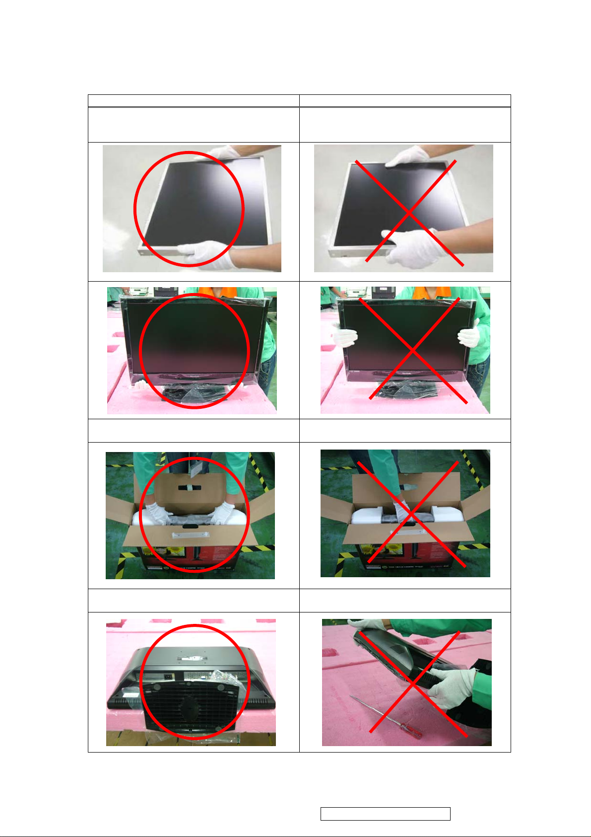
5.2. Handling and Placing Methods
ViewSonic Corporation
2
VT2430-1M
Correct Methods: Incorrect Methods:
Only touch the metal frame of the LCD panel or the
front cover of the monitor. Do not touch the surface
of the polarizer.
Surface of the LCD panel is pressed by fingers and
that may cause “Mura”
Take out the monitor with cushions Taking out the monitor by grasping the LCD panel.
That may cause “Mura”
Place the monitor on a clean and soft foam pad. Placing the monitor on foreign objects. That could
scratch the surface of the panel or cause “Mura”
Confidential - Do Not Copy
Page 6
2. Specification
ViewSonic Corporation
3
VT2430-1M
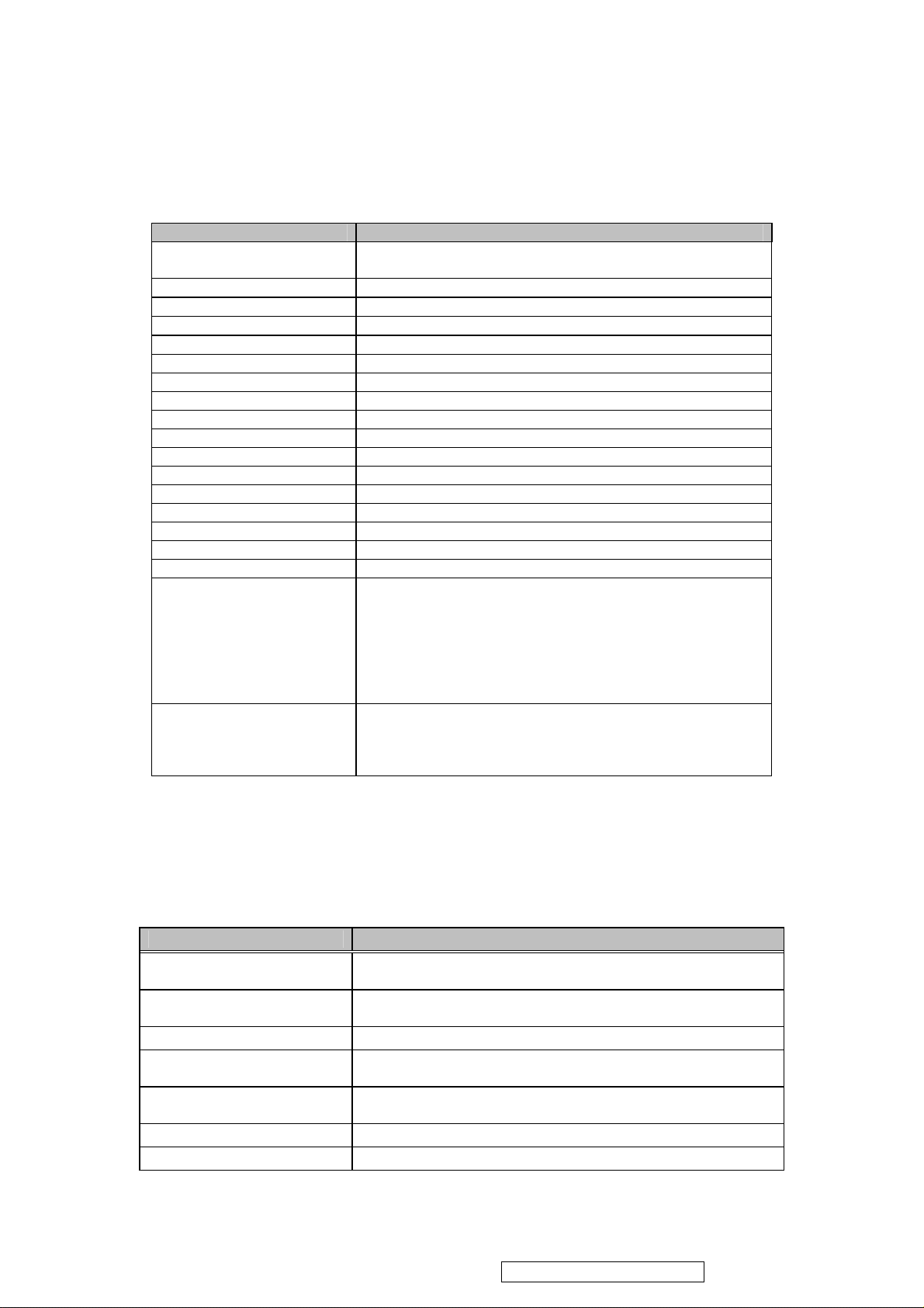
LCD panel of this product shall be provided by “CMO” with a model number of M236H1-L01.The
following table defines this panel specification. Any changes in panel must be pre-approved by
ViewSonic in written.
Parameter Specification
LCD Type
LCD Interface 1-Channel LVDS
Resolution (Native) 1920 x 1080
Display Area 23.6” diagonal; 521.28 (H) x 293.22 (V) mm
Pixel Pitch 0.2715 (H) x 0.2715 (V) mm
Viewing Angle H = 170, V = 160 with CR≥10 (Typical)
Contrast Ratio 1000:1 (Typical)
Brightness 300 nits (Typical)
Response Time 5 ms, (Typical), g-g
Brightness Uniformity 75% (Min), measured per panel spec.
Chromaticity(CIE1931) White-x:0.313,White-y:0.329 (Standard Mode Only)
Colors 16.7M (8-bits)
Surface Treatment Hard coating (3H)
Backlight 4 CCFLs (Cold cathode Fluorescent Lamp)
Preset Color Panel Default
Gray Scale 0-255
Rated Life (Backlight) > 50KHrs*(ILO at 3.0mA)
Front Screen Artifacts
Panel Acceptance Spec
Note: Also refer to the panel defect acceptance specification.
Panel performance characteristics “ MUST BE” met in all display modes/inputs at standard test
conditions.
1. RF Tuner
RF tuner of this product shall be provided by “Samsung DTVS205CH201A” for NTSC/ATSC. The
following table defines this tuner specification.
a-Si TFT Active Matrix Wide Color, Transmissive Mode,
Normally Black
VS Standard:
a.) No Visible Streaking, Sag or Smearing artifacts when
driven by the specified video cards (see 7.1 General Test
Equipment) in the primary mode (VGA & 60 Hz) and after
user adjustment
b.) No image drift or lose fine-tune settings due to panel
temperature change.
Refer to the panel acceptance criteria specification.
Note: Intermittent and/or Display Pattern defects which result
in further bright or dark dots will be counted individually
against the above specification.
RF Tuning Range
RF Tuner Sensitivity (S/N
Ratio at un-weight)
Channel Bandwidth NTSC/ATSC/Digital Cable: 6 MHz Maximum
CVBS Characteristics:
Video Amplitude Signal
Audio Characteristics:
SIF out level
Compatible system TUNER NTSC/ATSC/QAM
Compatible system AV NTSC M
Parameter Specification
NTSC/ATSC: 55.25 to 803 MHz, 2-69 Channels for Off-Air and
1-125 Channels for CATV
44 dB (min.)// 48 dB (max.)
0.8(min.)–1.2(max.) V
500mV (typ.)
Confidential - Do Not Copy
Page 7
2. Video
N
ViewSonic Corporation
4
VT2430-1M
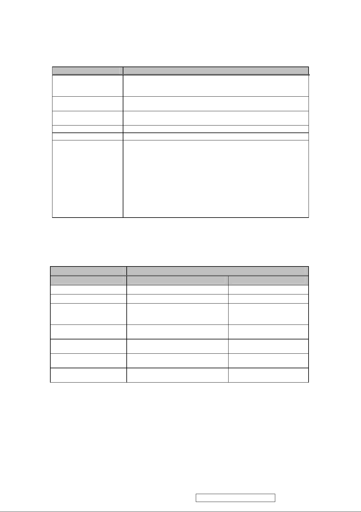
Built-in A/D converter shall provide analog to digital converter for this product.
Input Parameter Specification
CVBS Characteristics:
Video Amplitude Signal
DC Level Sync Pulse
S-Video Characteristics:
Video Amplitude Signal
Y, Pb, Pr Characteristics:
Video Amplitude Signal
Video Bandwidth
HDMI Characteristics Panel Link T.M.D.S HDMI-1.3
RGB Characteristics:
Signal Type
Sync Type
Input Signal Rating
Sync Level:
Frequency Range
Pixel Color
DDC Compliance
EDID Data Table
3. Audio
Audio amp of this product shall be provided by “YAMAHA” with a Model Number of YDA148 .
“MST” MSD2248AL for VT2430-1M shall be used as sound processor. In addition, a pair of speakers
shall be integrated within this product. The audio signals of this product shall comply with the
specification listed in the following table.
Parameter Specification
Tuner Input Base band Input
Power Output Max Rating 5W at 10 % T.H.D Distortion 5W at 10% T.H.D Distortion
Speaker Impedance main speaker :8 Ω main speaker :8 Ω
Line In
Line Out earphone jack
Flatness of Amplitude
Response
Total Harmonic Distortion
(Po=0.1 to 1 W, f=1KHz)
Signal to Noise:
0.7(min.) – 1.1(max.) V
Typical. 0.3 V
Y : 1.0Vp-p W / Neg. Sync (IN 75 Ω )
C : 0.285Vp-p (IN 75 Ω )
Y:1.0Vp-p (IN 75 Ω)
Pb:0.7 Vp-p(IN 75 Ω),Pr:0.7 Vp-p (IN 75 Ω)
TSC: 6 MHz Maximum
Analog VGA
TTL, Separate Sync, with 2.2KΩ pull-down resistors
1250mV Max without damage to the product, 0-700 mV Full Range
2.5-5.25 V
Horizontal: 30-82K Hz, Vertical: 55-75 Hz
16.7 M
DDC2B Compliant, Rev 1.3
Refer to Appendix
NTSC: BTSC Mono / Stereo(standard)
PAL: FM Mono / Stereo(standard)
+/- 3 db (at 1KHz @1W) +/- 3 db (at 1KHz @1W)
<2% <2%
12 dB (100Hz to 1KHz)
8 dB (1kHz to 10kHz)
500 mV rms (Typ)
1.6 V rms (Max)
Impedance: 600 ohms
500 mV rms
15 mW@32Ω
35 dB (100Hz to 10 kHz)
Confidential - Do Not Copy
Page 8

4. Electrical
ViewSonic Corporation
5
VT2430-1M
The following table defines the electrical specification of this product.
ELECTRICAL SPECIFICATION
1 Power Input Voltage Range 100-240VAC +/- 10% Wide Range
2 Input Frequency Range 47-63 Hz
3 Input Current 1.0A @ 115VAC // 0.5A @ 230VAC
Max in < 80A (with fully loaded power supply) at 230Vac
4 Power Supply Inrush
5 Power Consumption: 60 W (Normal), 75W (Max) // Stand by: < 2 W
6 Interference with RF and Video
7 Electromagnetic Compatibility
Power Supply Transient Immunity
8
(Supply Transients and Outage)
9 Surge Immunity Test
Power Supply Missing Cycle
10
Immunity
11 Power Supply Acoustics
12 Efficiency >= 80% @ full load, nominal line
13 Leakage Current <0.5mA @ 240VAC
14 Power Saving(DPMS) N/A
15 Recovery Time < 3 sec.
16 Power Factor Correction Compliant with EN61000-3-2
Shall not result in permanent failure of power supply
(including blown fuse)
There shall be no visible interference between power supply,
RF and video signals. This applies to all available RF
channels and video modes.
This product shall adhere to the compatibility and immunity
specifications in FCC.
Able to withstand an ANSI / IEEE C62.41 – 1980 2000V
ring wave with no damage.
Able to withstand 1.25X nominal Line Voltage for one cycle
with no damage.
Function properly without reset or visible screen artifact
when 1/3 cycle of AC Power is randomly missing.
The Power Supply shall not produce audible noise that would
be detectable by the user (Excluding Power Supply Fan).
“Audible” shall be defined in accordance with ISO 7779
(DIN EN27779:1991).
Power Switch noise shall be Excluded.
5. Firmware & OSD
The product firmware of VS12335-1M shall have a firmware version of V2.00EB0. Any
changes/revisions afterward shall also be pre-approved by ViewSonic in written. For VS12335-1M,
its firmware shall have a built-in frequency table for NTSC/ATSC off-air TV/CATV, and with MTS
implementation.
All audio/video and other output adjustments shall be performed by using an On Screen Display (OSD)
via a Remote Control Unit (RCU) in conjunction with the front panel adjustments.The following tables
list the OSD functions supported by VS12335 -1M.
OSD Table for VS12335-1M
Picture Mode Standard,Dynamic,Soft,Personal
Contrast 0~50~100
Brightness 0~50~100
Sharpness 0~50~100
PICTURE
Tint -50~0~+50
Color 0~50~100
Color Mode Cool, Normal, Warm
Zoom Mode Full, Movie Scale, Zoom In,4:3
Noise Reduction Standard, Strong, Weak, Off
Confidential - Do Not Copy
Page 9
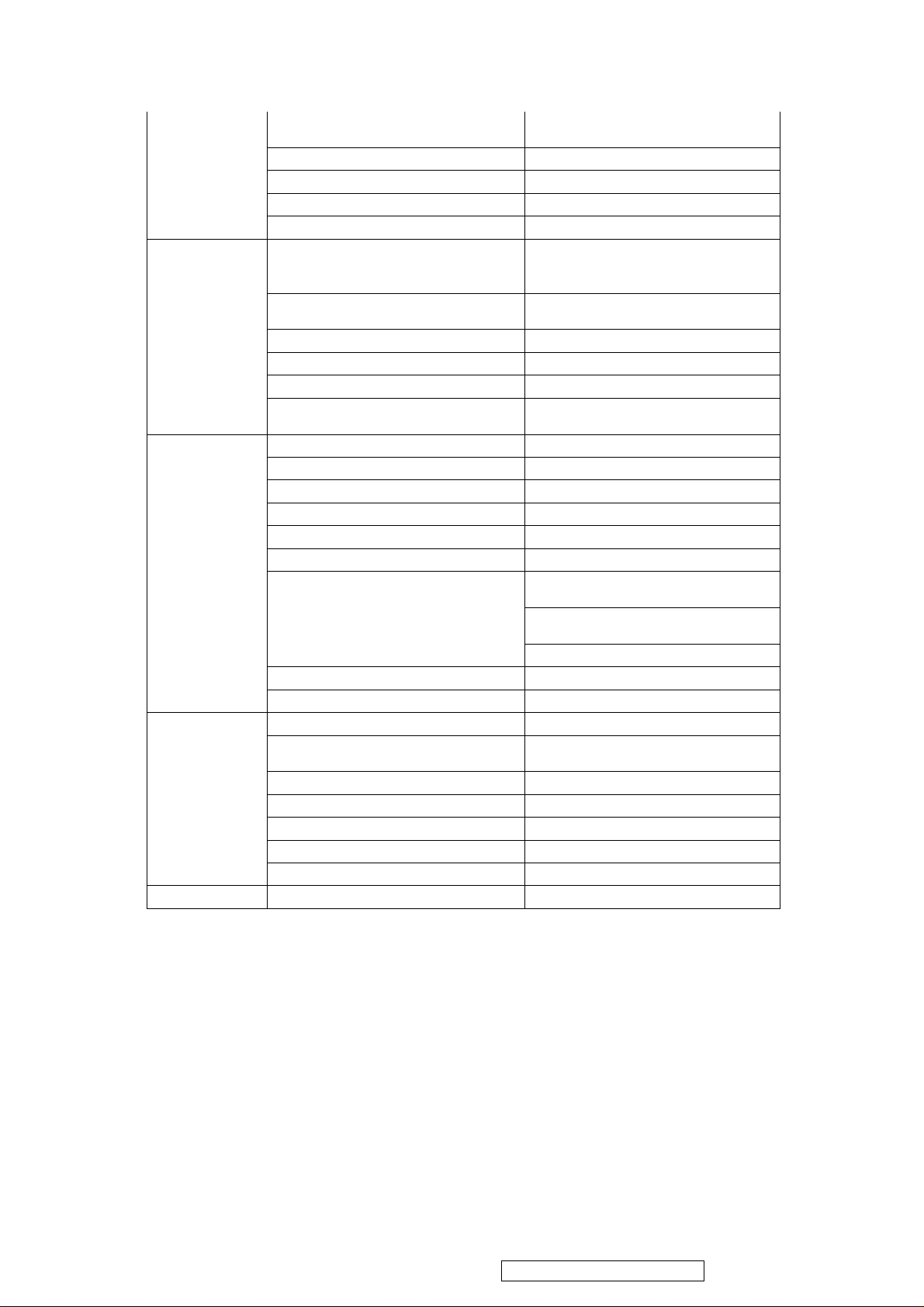
Sound Mode
ViewSonic Corporation
6
VT2430-1M
Treble/Bass Bass, Treble, Balance
ADUIO
TIME
OPTION
CHANNEL
LOCK Enter Password
6. Remote Control Unit (RCU)
An IR remote control unit shall accompany this product along with battery. In addition, this remote
control unit shall have an operational distance of 5 meters and an operational angle of 15 degrees for
both horizontal and vertical. Besides the key-code and protocol has fully conformed to VS standard.
Prefer Language(ATSC) English, French, Spanish
Surround Sound On, Off
Audio Only On, Off
Sleep Timer
Time Zone
DST On, Off
Time-Format 12/24-hour
Auto Sync On, Off
Clock
Menu Language English, French, Spanish
Transparency 0%,25%,50%,75%,100%
OSD Time Out 5,15,30,45,60 sec.
Closed Caption CC off, CC on, CC on mute
Basic Selection off, CC 1~4 Text 1~4
Advanced Selection(ATSC) off, Service 1~6
Option(ATSC)
DCR On, Off
Restore Default Yes, No
TV Source Air, CATV
Auto Scan
Favorite
Show/Hide
Channel No.
Channel Label
DTV Signal
Standard, Music, Movie, Sports,
Personal
OFF,
5,10,15,20,30,45,60,90,120,180,240
Min
Pacific, Alaska, Eastern, Central,
Mountain, Hawaii
Year, Month, Day, Hour, Min, OK,
Cancel
Option, Font style, Front size, Front
edge style
Front edge color, FG color, BG color, F
G Opacity
GG Opacity
Scan all channels, Digital channel only,
Analog channel only
Confidential - Do Not Copy
Page 10
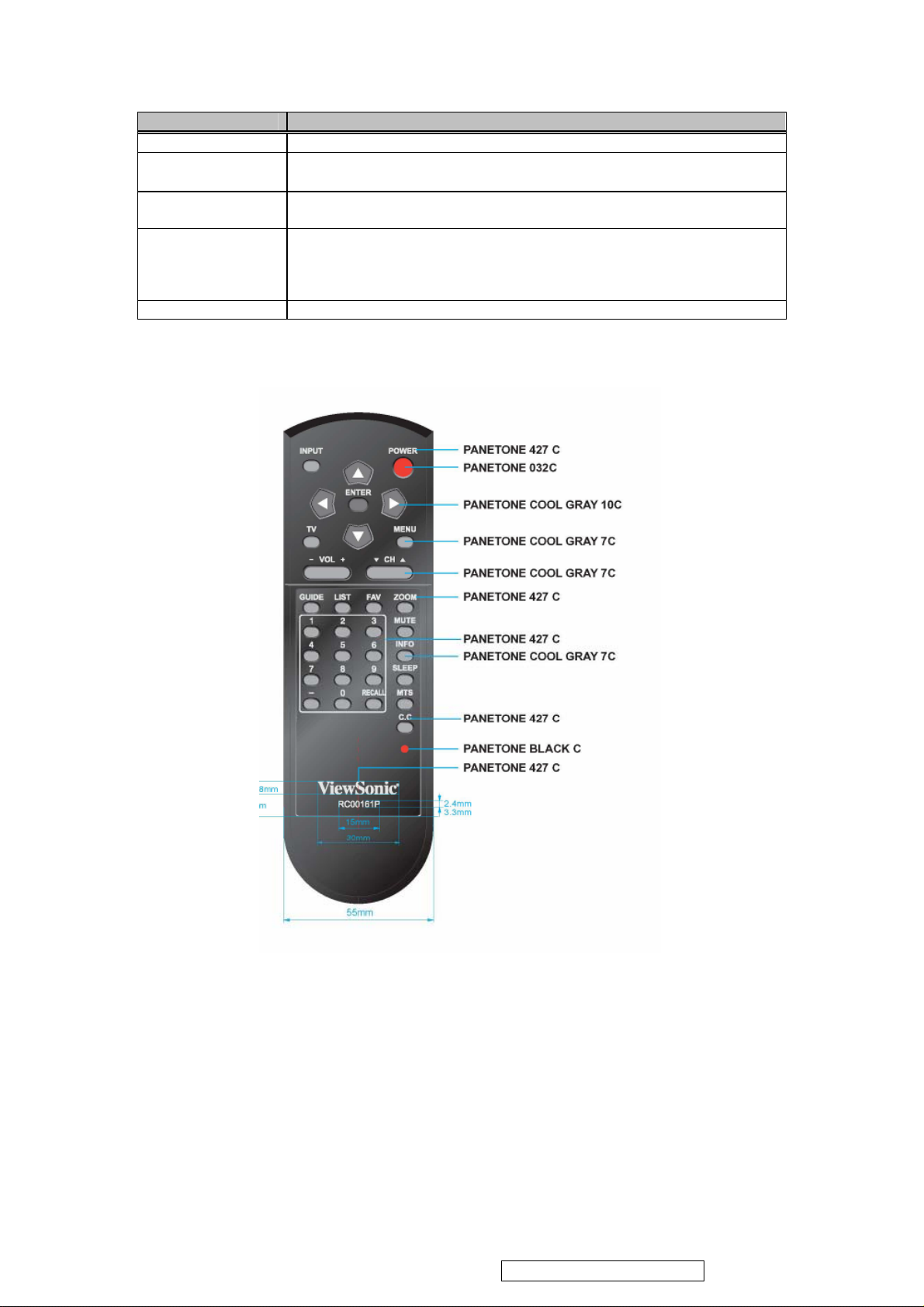
Parameter Specification
ViewSonic Corporation
7
VT2430-1M
Type IR; Made by Sighter Electronics Co., Ltd.
Range
Life Testing
(Buttons)
Color
Protocol VS key-code & protocol.
Off axis ± 15° ≥ 5M
On axis: ≥ 7M
100,000 cycle operations at a rate of 20~30 cycle / minute without load (with
battery)
Painting Color - PANTONE 427C (Black for front & back cover)
Power Key - PANTONE 032C (RED)
Key Pads – PANTONE 10C & PANTONE 7C(Cool Gray)
Texts Printed on Front Cover and Key Pads - PANTONE 427C
Confidential - Do Not Copy
Page 11
ViewSonic Corporation
8
VT2430-1M
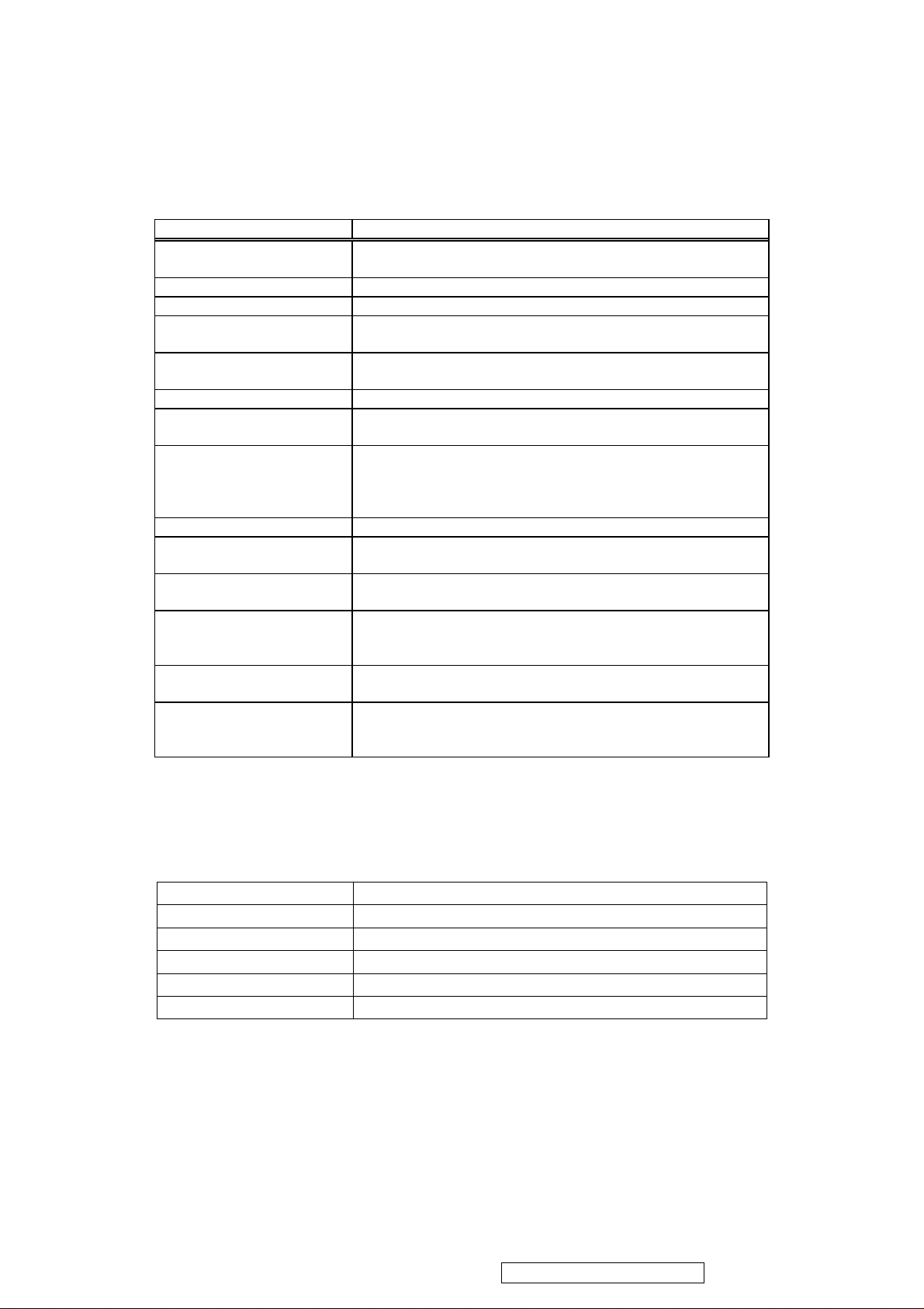
7. Mechanical
The following table defines the mechanical specifications of this product for both chassis and
cabinet.
Parameter Specification
Dimension
W/O stand
Net Weight 7.0kg
Chassis Plastic Material ABS (ABS HB )
External Plastic Chassis
Components
Internal Plastic Cabinet
Components
Exterior Chassis Color Refer to- Product ID Guide
Chassis Component’s Color
Difference
Chassis Color Drift Due to
UV-Light
Chassis Texture Front Bezel:(N/A ;) Back Cover:N/A ; MT11010)
Molded Plastic Workmanship shall be inspected according to ViewSonic
Screen Printed Parts, Bird
Logo Recess
Rear Label A label identifying the product name, model/serial number and
Wall- Mount 100mmx100mm VESA high hole (n=4), M4 x 10mm, pitch
Sample Sample of textured color chips, plastic material specification,
In addition, all exterior surfaces shall have uniform texture/color. The maximum acceptable
gap between the buckets to bezel plastic pieces shall be within 1.0mm. The maximum
acceptable gap between LCD panel and bezel shall be within 1.3 mm.
8. Environmental
The following table defines the operational/storage conditions of the product.
Operating Temperature
Humidity 10% ~ 65% non-condensing
Altitude 0 meter to +2000 meters above sea level
Storage Temperature
Humidity 0 ~ 90% non-condensing
Altitude 0 meter to 12,000 meters above sea level
W=566.7mm, H=441.9mm and D=211.0mm
W=566.7mm, H=386.7mm and D=85mm
Plastic Chassis, Cover, Stand, Len and Button
N/A
Refer to- Product ID Guide
The color drift due to UL-Light shall be less than 10 “Delta E”
in the 1976 CIE L*a*b color space. Testing shall be
performed according to the requirements of ASTM Test Method
D4459-93.
Molded Plastic Parts Specification, VSCMPPSPEC001V1.2.
Artwork shall be provided and confirmed by ViewSonic.
FCC ID/Logo shall be placed into the rear label recess located
on the rear panel of the chassis.
=0.7mm screw mounting kit not included.
and Material Safety Data Sheets shall be submitted to
ViewSonic prior to Mass Production Release.
0°C to +40°C
-20°C to +60°C
Confidential - Do Not Copy
Page 12
3. Front Panel Function Control Description
ViewSonic Corporation
9
VT2430-1M
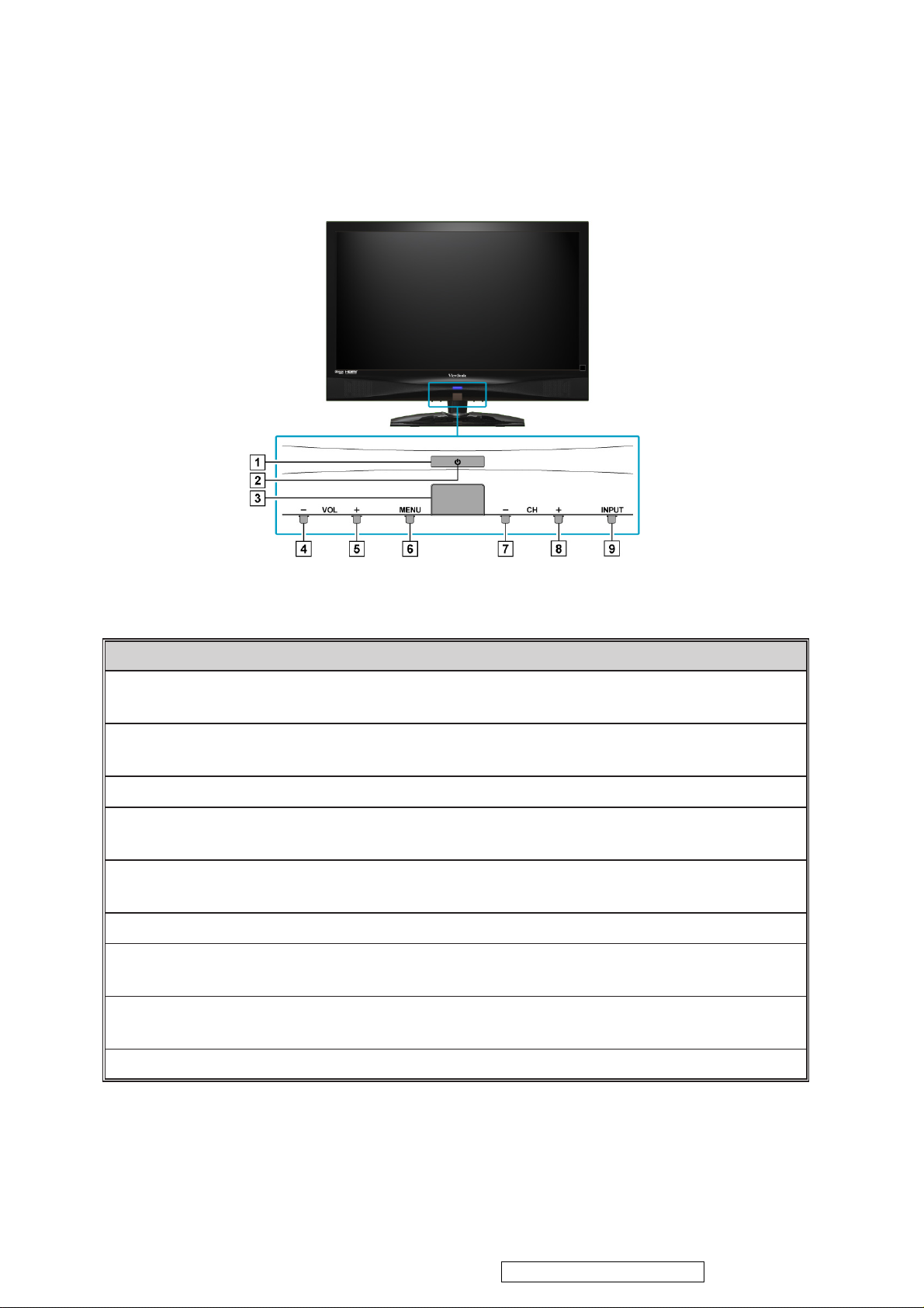
Front View of the Product
Item Description
Power ON/OFF button
1
Power LED Indicator
2
Remote Control Receiver
3
Volume Down
4
Volume Up
5
MENU
6
CH Down
7
CH Up
8
INPUT
9
Turn the power on from standby mode or turn the power off to
return to the standby mode.
Lights up in blue when the TV is turned on. Lights up in orange
when the TV is in standby mode.
Receives IR signals from the remote control.
Decrease sound volume or adjust a highlighted control while in
OSD menu.
Increase sound volume or adjust a highlighted control while in
OSD menu.
Turn OSD menu ON/OFF.
Channel down when source is TV, or select a control while in
OSD menu.
Channel up when source is TV, or select a control while in OSD
menu.
Select input source.
EL
Confidential - Do Not Copy
Page 13
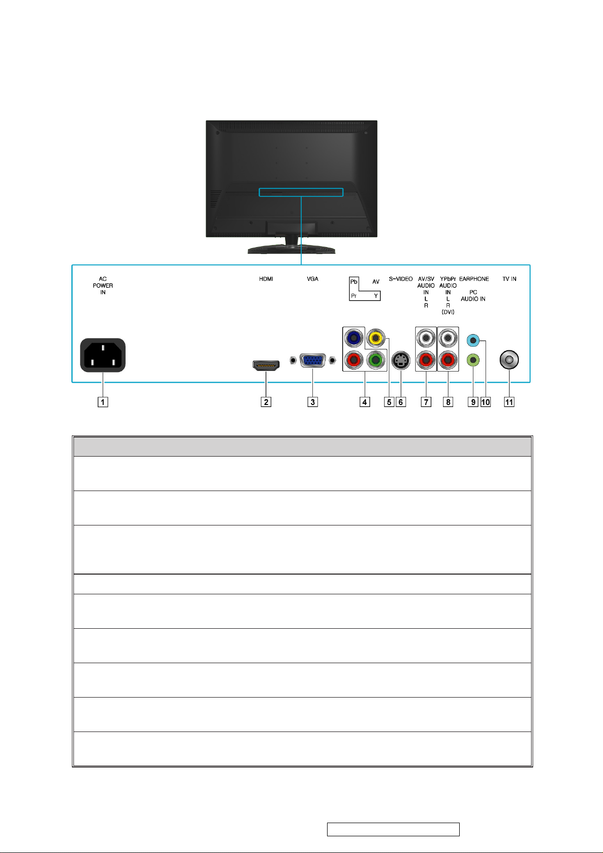
Rear View of the Product
Item Description
1 Power (AC input)
Plug-in the supplied AC Power cord and connect to the AC input
power source.
2
HDMI Input Terminal
Connect this port to the HDMI/HDMI-DVI jack of the compatible
equipment.
3
VGA signal input
Connect a 15-pin D-sub RGB cable to the RGB output of your
computer and the other end to the RGB input on the rear of the LCD
TV.
4
YPbPr signal input
Connect this jack to the YPbPr output of A/V device.
5
Composite Video input
Connect this jack to the composite video output connectors on your
A/V equipment.
6
S-Video input
Connect the S-Video cable from the compatible device to this
connector on the rear panel of the LCD TV.
7
AV/ S-Video Audio input
(left/ right)
Connect the Audio in cable for AV/ S-Video from this jack to the
corresponding connectors on your A/V device.
8
YPbPr/ DVI Audio input
(left/ right)
Connect the Audio in cable for YPbPr/ HDMI-DVI from this jack to
the corresponding connectors on your A/V device.
9
PC Audio input
Connect the RGB Audio Out on your computer to the RGB Audio
on the rear of the LCD TV.
ViewSonic Corporation
10
VT2430-1M
Confidential - Do Not Copy
Page 14

Item Description
ViewSonic Corporation
11
VT2430-1M
ENGLISH
10 Headphone Jack
11 TV Input Jack
Connect to your headphones. By connecting the headphones, you can
listen to the sound from the TV on headphones.
If you connect the headphones, the TV speakers will be muted.
*
Connect this jack to your Cable or VHF/UHF antenna.
Confidential - Do Not Copy
Page 15
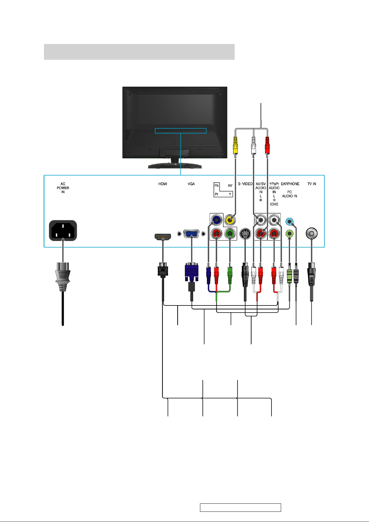
Other Equipment
ViewSonic Corporation
12
VT2430-1M
DVD Player/
VCD Player/
Game system
AC power
socket
DVD Player/
Personal
Computer
Digital
cable box
Personal
Computer
Blu-ray Disc
Player/ PS3
Personal
Computer
VCD Player/
Game system
DVD Player/
VCD Player/
Game system
Digital satellite
receiver
DVD
Player
HeadphoneDVD Player/
Audio
system
VHF/ UHF
CABLE
• Please refer to the Quick Start Guide (supplied) when connecting the other equipment to
your LCD TV.
Confidential - Do Not Copy
Page 16
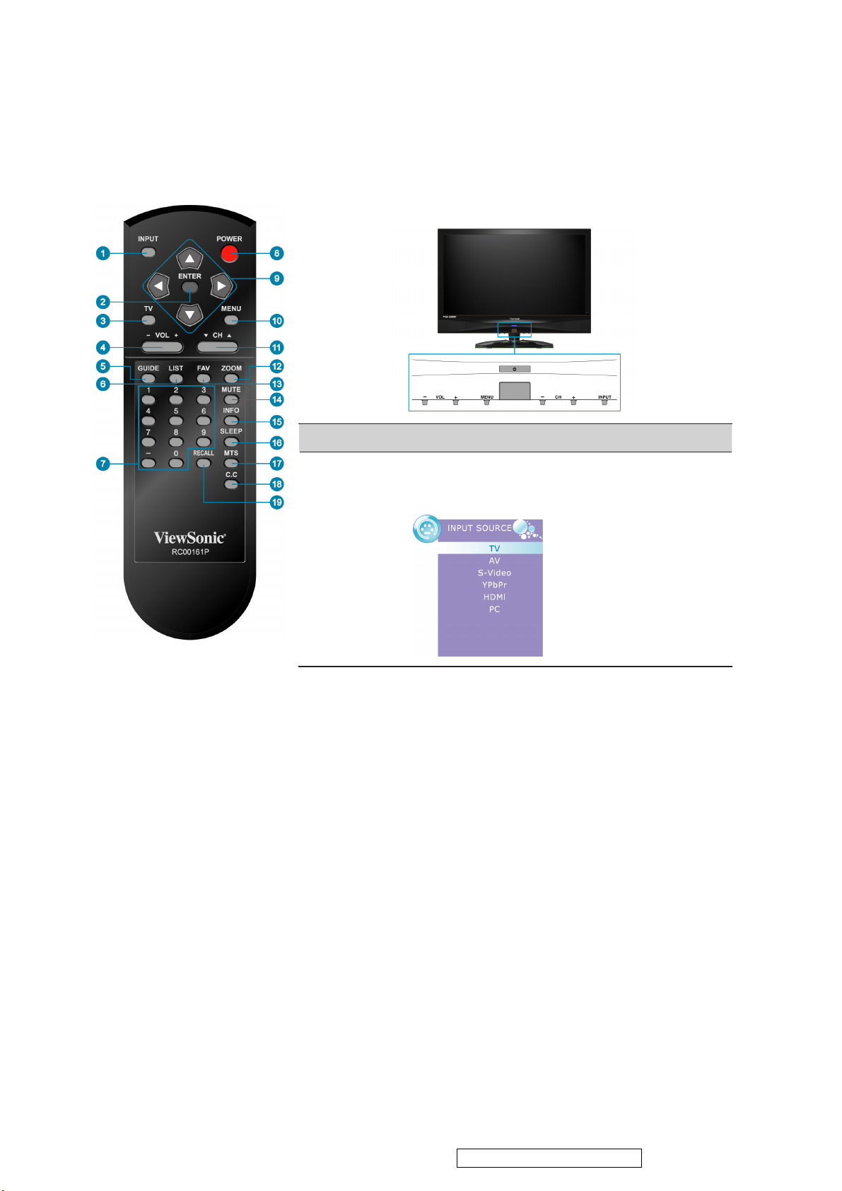
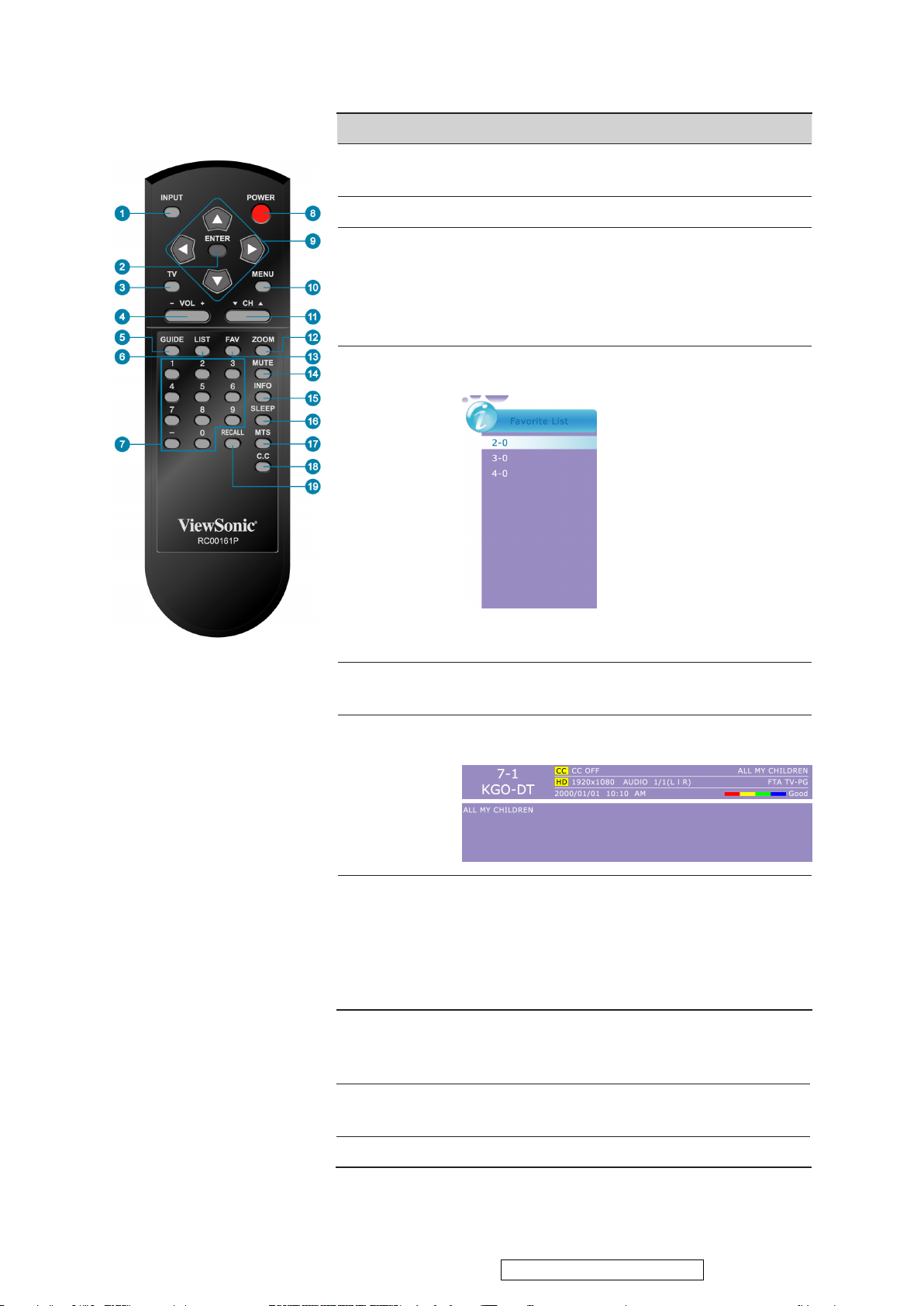
Remote Control
Buttons located at the bottom of the LCD TV will operate the same
as these buttons on the remote control.
Button Description
1 INPUT
Press to display the INPUT source list and select
the source with
▲/▼
buttons. To conrm the
selection, press ENTER.
ViewSonic Corporation
13
VT2430-1M
ENGLISH
Confidential - Do Not Copy
Page 17
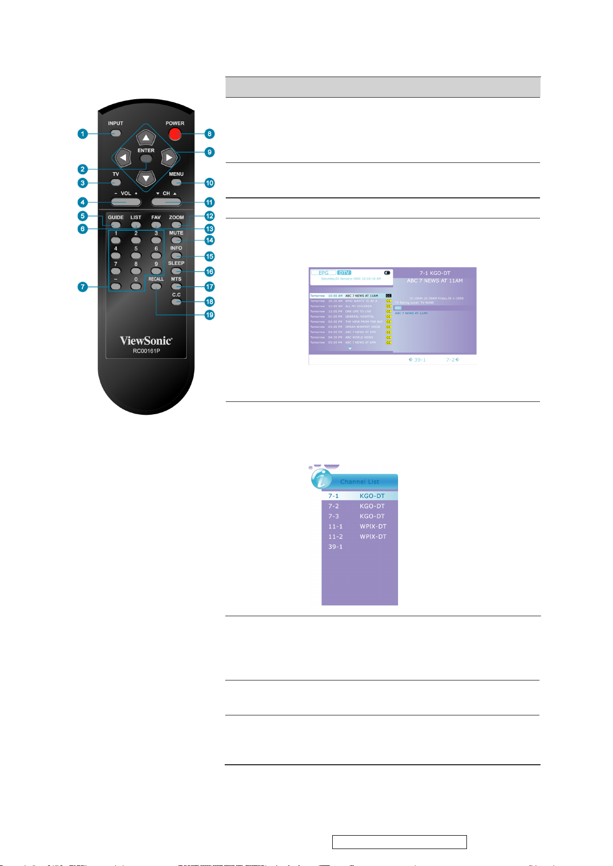
Button Description
ViewSonic Corporation
14
VT2430-1M
ENGLISH
2 ENTER
3 TV
4 - VOL +
5 GUIDE
Press to conrm the selection in the OSD menu, or
to enter the OSD menu you select.
Press ENTER after you input channel numbers
will change channels immediately.
Press to direct to TV source when in any other
source.
Press to adjust the volume.
Press to display the Electronic Program Guide
(EPG). It contains the program information for the
channel you’re watching.
The picture here shows an example of the GUIDE
*
screen in a DTV source.
6 LIST
7 0~9, -
number
buttons
8 POWER
Press this button to show a small window showing
program list, you can scroll through the list to select
the channel you want directly without using the
button.
/▼
Press 0~9 and “-” to select a channel. After you
input the channel numbers, press ENTER button
to direct to the channel immediately, or wait for 3
seconds to change automatically.
Press this button to turn the power on from standby
mode. Press it again to return to the standby mode.
▲
9 ▲▼◄►
buttons
Press these buttons to navigate the OSD menus. ▲/▼
is for function select, and ◄/► is for function
adjustment.
Confidential - Do Not Copy
Page 18
Button Description
ViewSonic Corporation
15
VT2430-1M
10 MENU
11 ▼ CH ▲
12 ZOOM
13 FAV
Press to turn the OSD (On-Screen Display) menu
on.
Press to change the channels up or down.
Press this button repeatedly to select the screen size.
You can select from Full, 4:3,Movie Scale, and
Zoom In.
The digital TV HD signal is available in Full
*
and 4:3.
Press this button to show Favorite List and select your
favorite channels that have already been stored.
ENGLISH
14 MUTE
15 INFO
16 SLEEP
17 MTS
To preset favorite channels, use the Favorite item
*
in the TV menu.(see page 26)
Press to turn off the sound. To restore the sound,
press this button again, or press the VOL+ button.
Press this button to display the current state of the
LCD TV.
Press repeatedly to set the off timer. The function
is used to automatically shut off the LCD TV after
a preset period of time passed. There are several
times for choice – Off, 5 Min, 10 Min, 15 Min, 30
Min, 45 Min, 60 Min, 90 Min, 120 Min, 180 Min,
240 Min.
Press this button to choose the available sound
output that is preset by TV broadcasting station.
(EX: Mono, Stereo, SAP)
18 C.C
19 RECALL
Press to select the Closed Caption menu in the TV
mode.
Press to return to previous channel.
Confidential - Do Not Copy
Page 19
ENGLISH
ViewSonic Corporation
16
VT2430-1M
Operation
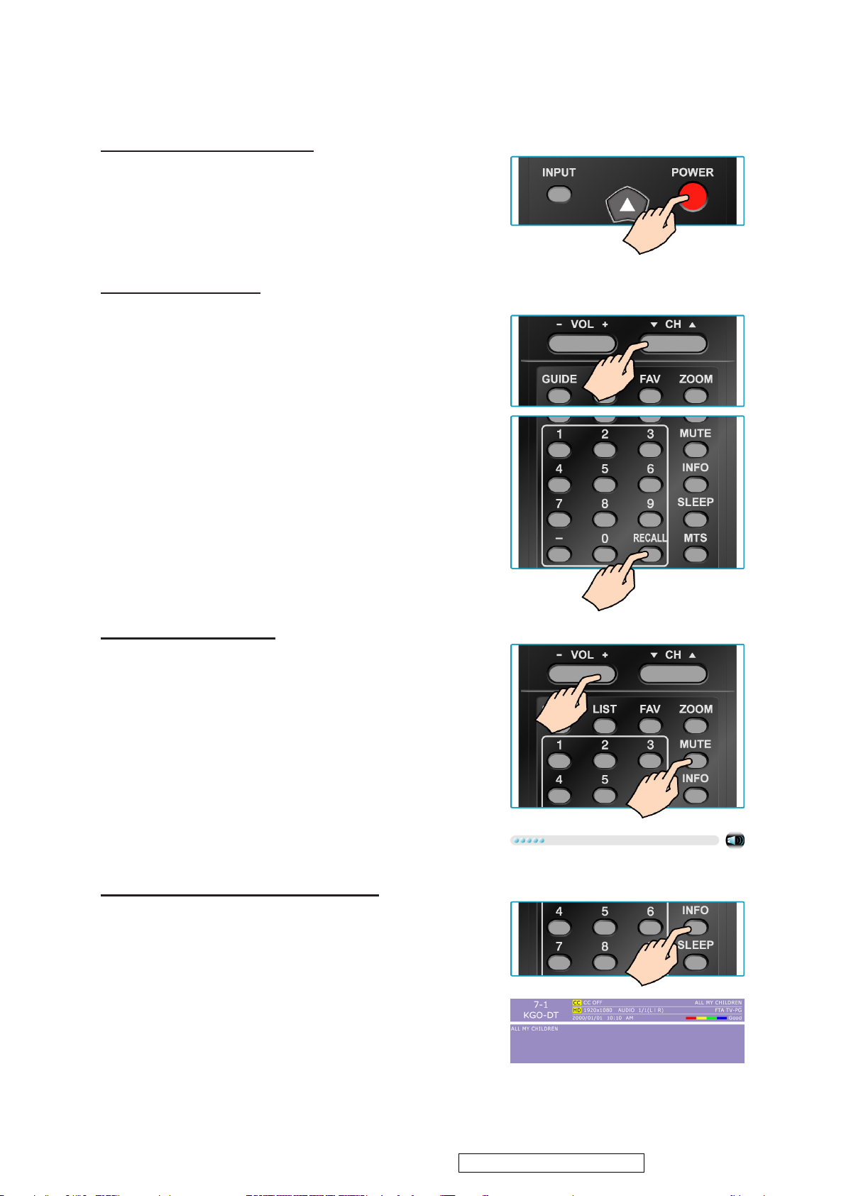
Turning the TV On and Off
Press the POWER button on the remote control.
You can also use the Power button on the front of the
panel.
Changing Channels
1. Using Channel Buttons
Press ▼CH▲ button to change channels, and the TV
changes channels in sequence. You will see all channels
that have been memorized. Channels erased or not
memorized will not be shown.
2. Using Number Buttons
(1) ATV
The “-” button has no function in ATV mode. Directly
press the number buttons to select channels.
(2) DTV
Use “-” button to select the sub channel in DTV.
Ex: Your desired number is 80-3.
Press 8 → press 0 → press “-” → press 3.
*Return to the previous channel, press RECALL
button.
Adjusting the Volume
Press VOL +/- to adjust volume.
To turn off the volume, press MUTE.
To restore volume, press MUTE again, or press VOL +/-
directly.
Viewing the Displayed Information
To display the current information of the LCD TV:
Press INFO, and the current state will be displayed on
the screen. (It shows all or some of the information about
Input, Channel, Resolution, Audio Type, etc., depending
on what input source it is in)
*The picture here shows an example of the INFO screen
in a DTV source.
Confidential - Do Not Copy
Page 20
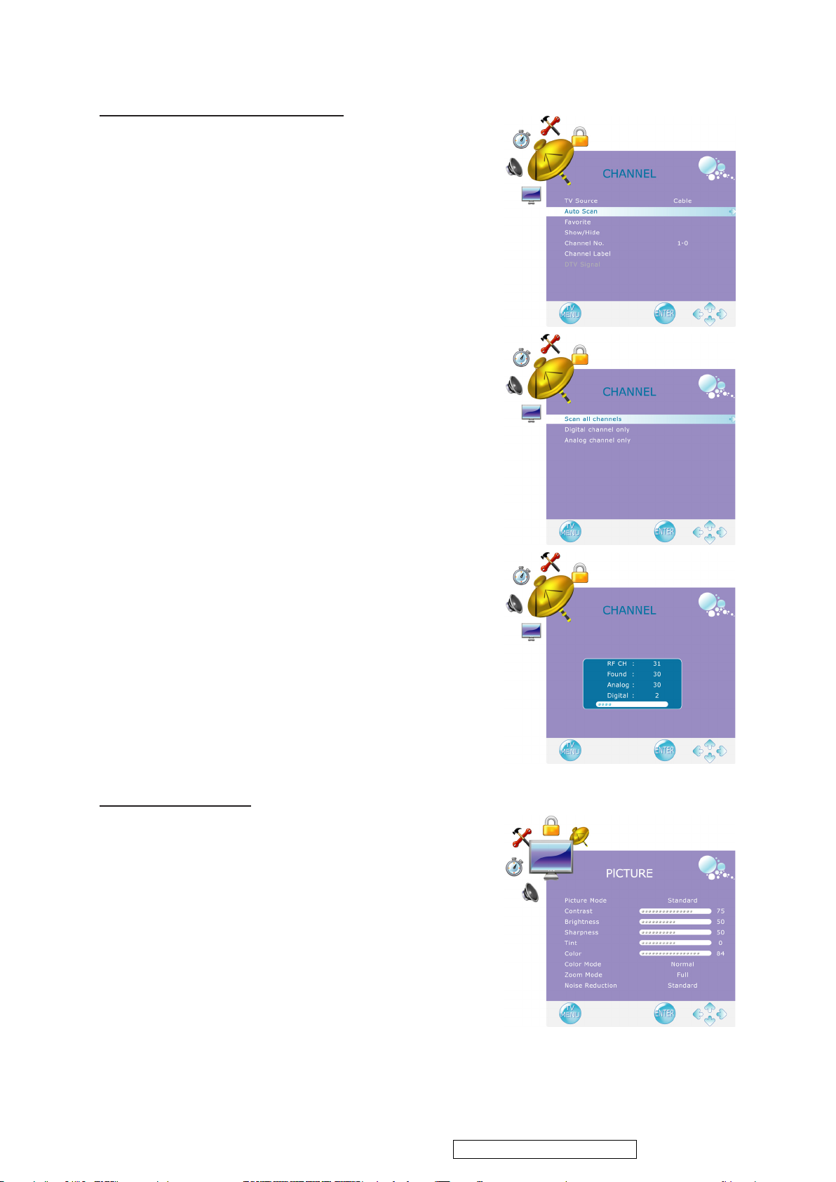
Storing Channels into Memory
ViewSonic Corporation
17
VT2430-1M
1. Press the MENU button to display the OSD main menu.
2. Press ◄ or ► to select the “CHANNEL” menu.
Press ▲ or ▼ to select “TV Source”, and use ◄ or ►
to select the antenna connection to “Air” or “Cable”.
Air: RF signal programs by “Air”.
Cable: RF signal programs by “Cable”.
3. Press ▲ or ▼ to select “Auto Scan”, then press ► to
enter.
4. Press ▲ or ▼ to select “Scan all channels”, “Digital
channel only”, or “Analog channel only” and press ► to
perform Auto Scan function.
To stop scanning, press MENU at any time.
5. The Auto Scan screen will be shown, and after it is
done, the screen will return to the rst found channel.
ENGLISH
Viewing the Menus
1. Press the MENU button to display the OSD main menu.
There are six top menus on the screen: PICTURE,
AUDIO, TIME, OPTION, LOCK, and CHANNEL.
2. Press ◄ or ► to select your desired top menu.
3. Press ENTER or ▼ to enter the menu you select.
4. Use ▲▼ to select the control you want to adjust.
5. When selecting the control with ►, press ► to enter
next level menu or enable the function. (► will only
appear when the control is highlighted)
6. Press ◄► to adjust or select the settings.
7. Press MENU to exit from the OSD menu.
Confidential - Do Not Copy
Page 21
ENGLISH
ViewSonic Corporation
18
VT2430-1M
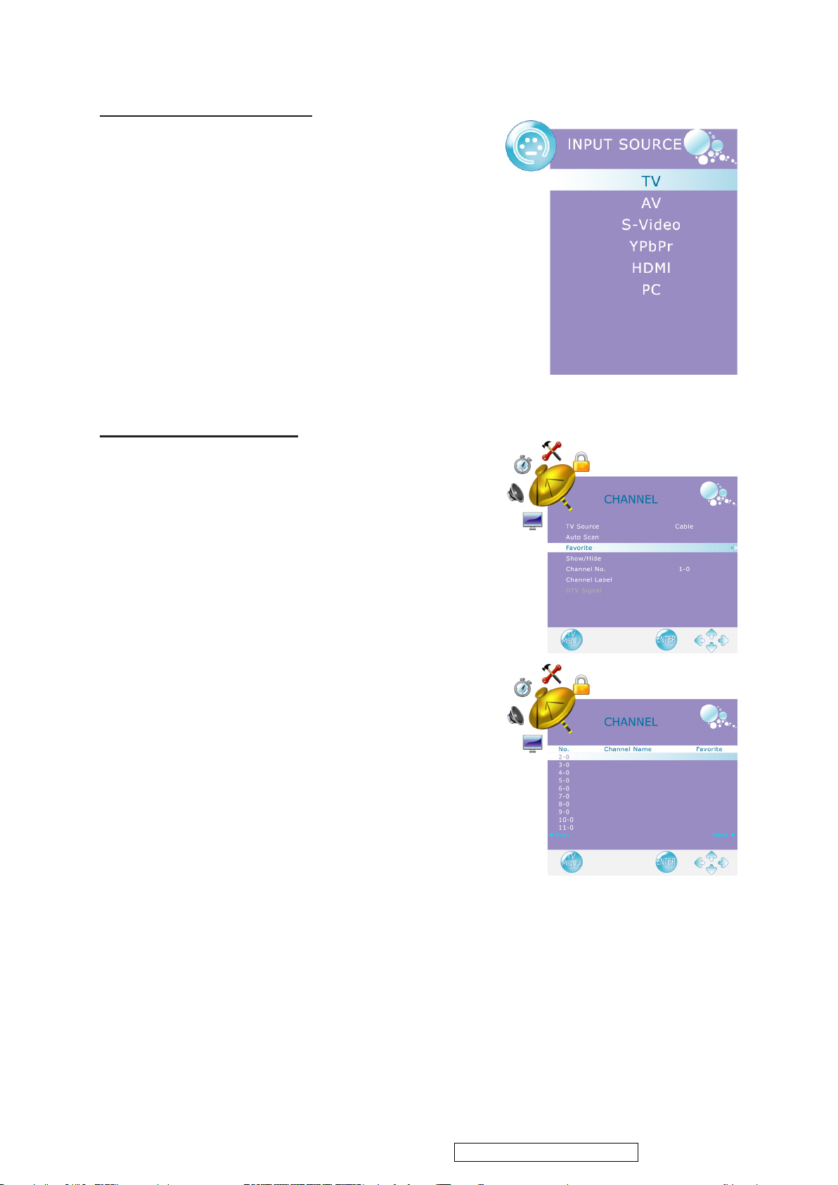
Selecting the Input Source
To select the TV or other external input sources connected
to the TV.
1. Press the INPUT button on the remote control.
2. Press ▲ or ▼ to select the required input source between
TV, AV, S-Video, YPbPr, HDMI, or PC.
3. To conrm the selection, press ENTER.
Favorite Channel Setting
To set your favorite channel into memory:
1. Press the MENU button to display the OSD main menu.
2. Press ◄ or ► to select the “CHANNEL” menu.
Press ▲ or ▼ to select “Favorite”, then press ► button
to enter “Favorite” setting.
3. Press ▲ or ▼ to select the channel you’d like to be your
favorite channel.
Press ENTER to conrm your selection.
4. To cancel the selection, Press ENTER again on the selected
channel.
5. Press MENU to exit.
*To view your favorite channels, press FAV button to
show Favorite List and select your favorite channels that
have already been stored.
Confidential - Do Not Copy
Page 22
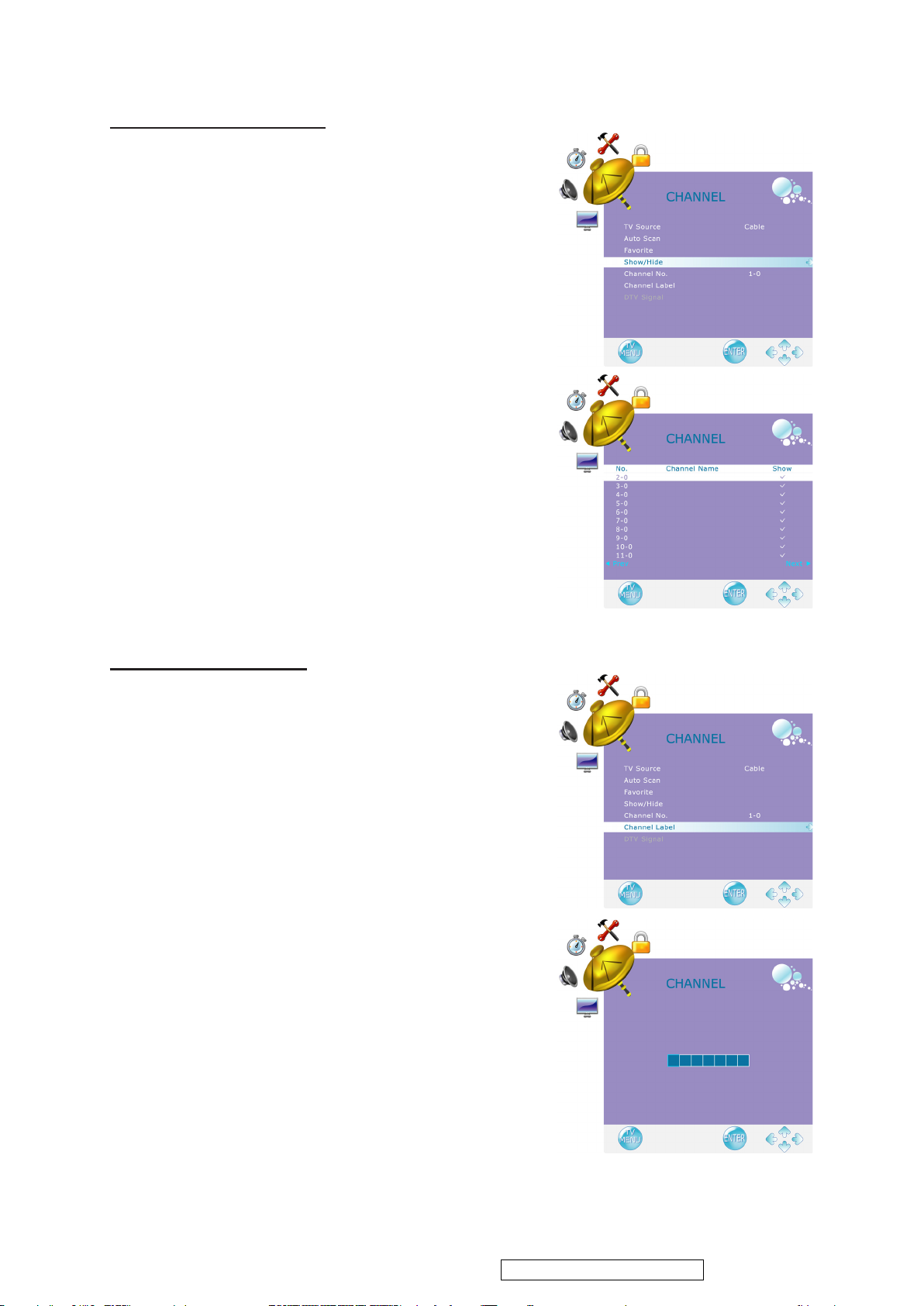
Adding/Erasing Channel
ViewSonic Corporation
19
VT2430-1M
When the channel is erased, it will not appear on the
screen when you browse the channels with ▼CH▲
button. To see the channel again, you must add the channel
or perform the “Auto Scan” (page 25) function again.
1. Press the MENU button to display the OSD main menu.
2. Press ◄ or ► to select the “TV” menu.
Press ▲ or ▼ to select “Show/Hide”, then press ►
button to enter “Show/Hide” setting.
3. Press ▲ or ▼ to select the channel you want to Show/
Hide, and check or uncheck it with ENTER button.
4. Press MENU to exit.
ENGLISH
Channel Name Setting
To edit a name for the current channel:
1. Press the MENU button to display the OSD main menu.
2. Press ◄ or ► to select the “CHANNEL” menu.
3. Press ▲ or ▼ to select “Channel No.”, then press ◄ or ►
to select the channel you want to edit the name.
4. Press ▲ or ▼ to select “Channel Label”, then press ►
button to enter “Channel Label” setting.
5. Use ▲ or ▼ to choose letters or signs, ◄ or ► to move
forward or backward.
6. After you input the channel name, press MENU or
ENTER to complete the setting.
7. Press MENU to exit.
Confidential - Do Not Copy
Page 23
ENGLISH
ViewSonic Corporation
20
VT2430-1M
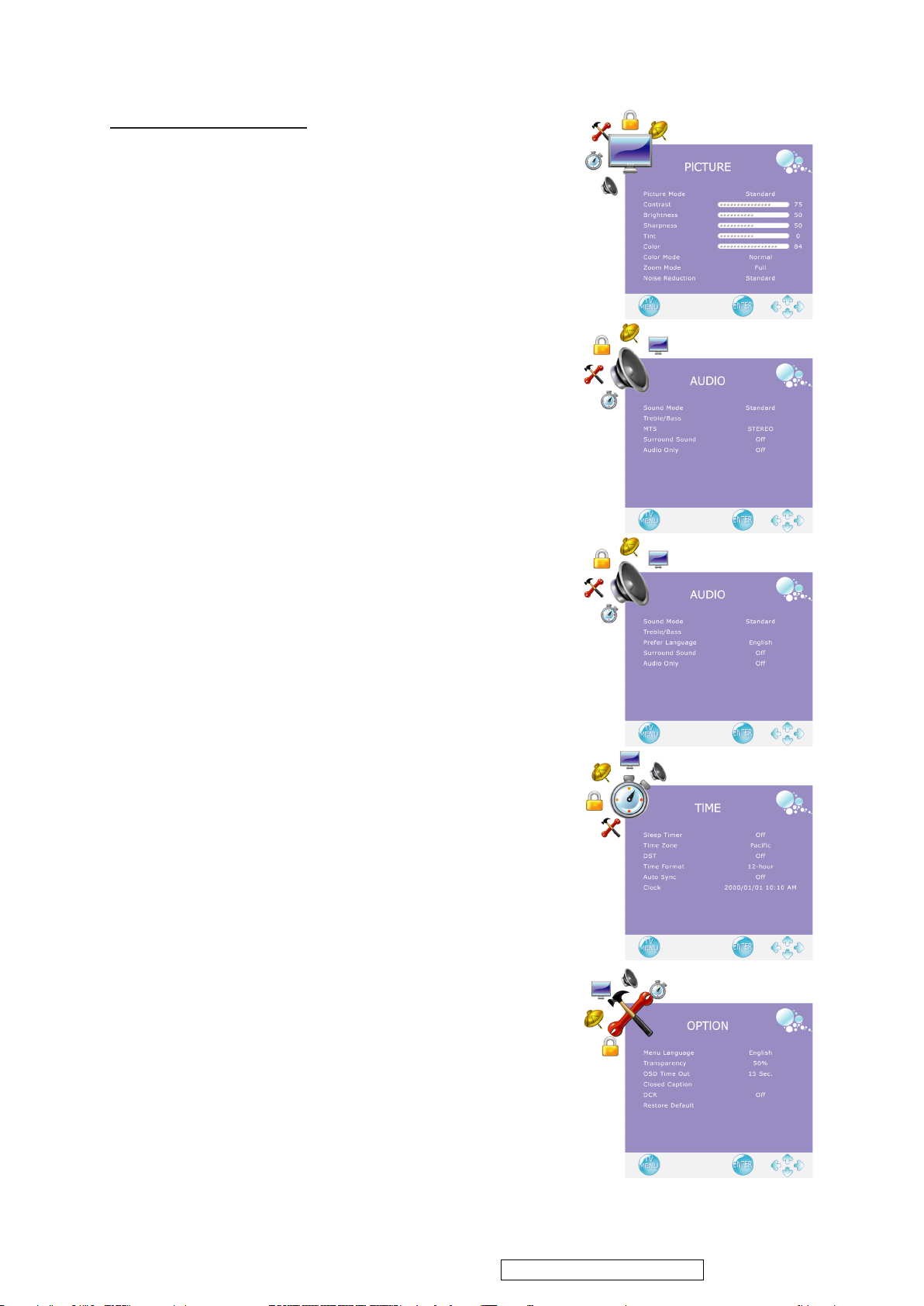
Adjusting the Settings
1.
(1) Press the MENU button to display the OSD main menu.
(2) Press ◄ or ► to select your desired top Menu.
(3) Press ▲ or ▼ to select the control of “Contrast”,
“Brightness”, “Sharpness”, “Tint”, “Color”, then press ◄
or ► to adjust the level.
(4) Press MENU to exit.
2.
(1) Press the MENU button to display the OSD main menu.
(2) Press ◄ or ► to select your desired top Menu.
(3) Press ▲ or ▼ to select the control of “Picture Mode”,
“Color Mode”, “Zoom Mode”, “Noise Reduction”,
“Sound Mode”, “MTS”, “Prefer Language” (in DTV mode),
“Surround Sound”, “Audio Only”, “Sleep Timer”, “Time
Zone”, “DST”, “Time Format”, “Auto Sync”, “Clock”,
“Menu Language”, “Transparency”, “OSD Time Out”,
“DCR” (Dynamic Contrast Ratio), then press ◄ or ► to
select your desired option.
(4) Press MENU to exit.
3.
(1) Press the MENU button to display the OSD main menu.
(2) Press ◄ or ► to select your desired top Menu.
(3) Press ▲ or ▼ to select the control with ►, including
“Treble/Bass”, “Closed Caption”, “Restore Default”, then
press ► to perform the function or enter detailed
settings.
Confidential - Do Not Copy
Page 24
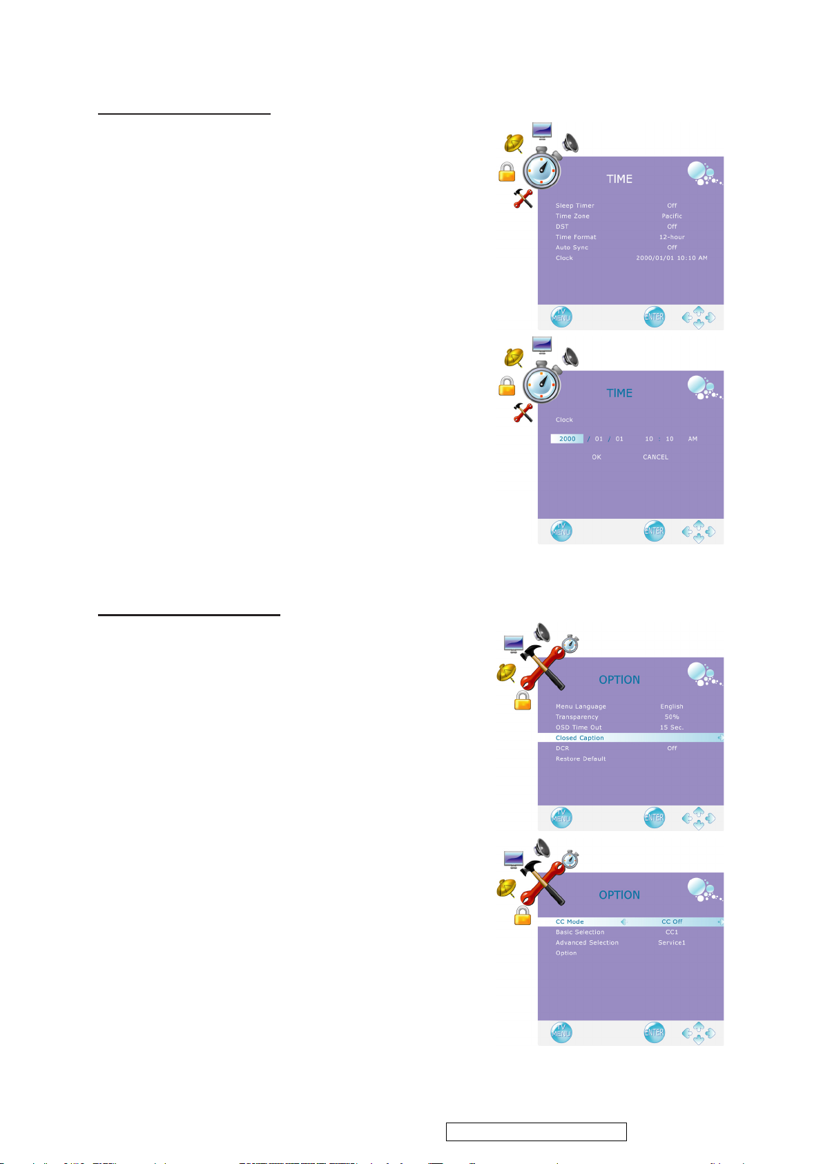
Setting up Time menu
ViewSonic Corporation
21
VT2430-1M
1. Press the MENU button to display the OSD main menu.
2. Press ◄ or ► to select the “TIME” menu.
3. Press ▲ or ▼ to select “Sleep Timer”, and press ◄ or
► to set the “Sleep Timer” from 5~240 min, or Off.
4. Press ▲ or ▼ to select “Time Zone”, and select the correct
time zone of your area with ◄ or ►. The displayed time
of “Clock” will be changed at the same time automatically.
To adjust “Clock”, select “Clock” and press ►. Use ◄
or ► to change between year/ month/ date/ hour/ minute,
▲ or ▼ to adjust. When you nish adjustment, select
“OK” and press ENTER to complete the setting.
*The “Clock” time can only be adjusted manually
when “Auto Sync” is set to “Off”.
5. Press ▲ or ▼ to select “DST” (Daylight Saving Time),
and select On or Off with ◄ or ► according to the time
zone of your area. The “Clock” time will change
automatically.
6. Press ▲ or ▼ to select “Time Format”, and ◄ or ► to
select 12-hour or 24-hour.
7. Press MENU to exit.
ENGLISH
Closed Caption Setting
1. Press the MENU button to display the OSD main menu.
2. Press ◄ or ► to select the “OPTION” menu.
Press ▲ or ▼ to select “Closed Caption”, then press ►
button to enter “Closed Caption” setting.
3. Press ▲ or ▼ to select CC Mode, Basic Selection, or
Advanced Selection, and use ◄ or ► to make your choice.
Basic Selection: To set basic analog closed caption
options. (CC1~CC4, TEXT1~TEXT4, Off)
Advanced Selection: To select closed caption signal
formats and set up caption modes for digital TV
channels. (Service1~6, Off)
Confidential - Do Not Copy
Page 25
ENGLISH
ViewSonic Corporation
22
VT2430-1M
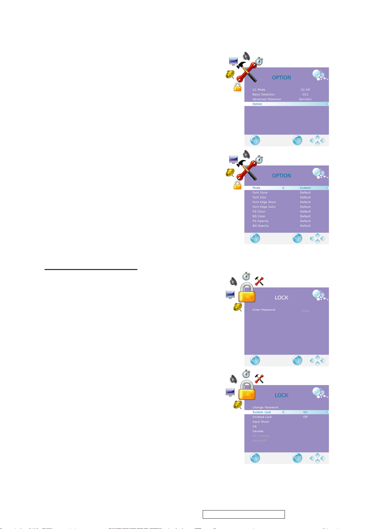
For detailed Close Caption setting:
1. Press ▲ or ▼ to select “Option”, then press ► to enter
“Option” setting.
2. Press ◄ or ► to select the Mode to be “Custom”, and then
use ▲ or ▼ to select desired options and use ◄ or ► to
adjust detailed settings.
*When you select the Mode to be “Default”, you can
not adjust the detailed settings.
Using the Parent Controls
1. Press the MENU button to display the OSD main menu.
2. Press ◄ or ► to select the “LOCK” menu.
3. Press ENTER or ▼ to enter Password.
4. Enter the password. (The default password is 0000)
5. Move to “System Lock”, and select “On” to enable the
detailed settings.
6. Move to “US” or “Canada” rating system.
Confidential - Do Not Copy
Page 26
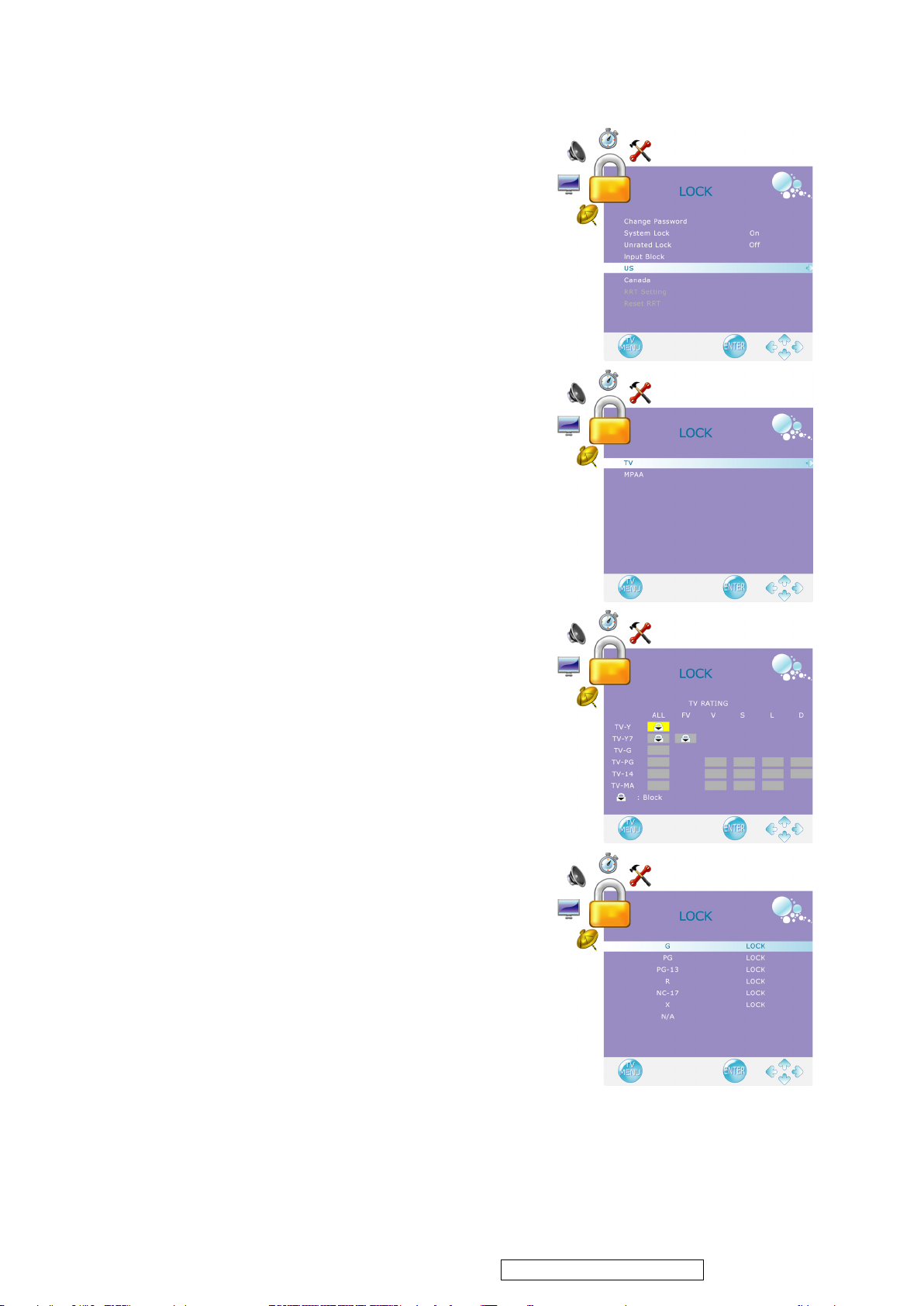
US: Press ► to set TV or MPAA ratings.
ViewSonic Corporation
23
VT2430-1M
(1) TV
1. Press ▲ or ▼ to select “TV”, then press ► to enter
“TV” rating system setting.
The following screen will allow you to customize
the following TV ratings:
Y (all children)
Y7 (older children)
G (general audience)
PG (guidance suggested)
14 (strongly cautioned)
MA (mature audience)
You can also customize the TV ratings for the
following content:
ALL (All types content)
FV (fantasy violence)
V (violence)
S (sexual situations)
L (adult language)
D (sexsual dialog)
ENGLISH
2. Press ENTER to set or reset each area.
3. Press MENU to exit.
(2) MPAA
1. Press ▲ or ▼ to select “MPAA”.
2. Press ▲ or ▼ to select your desired MPAA ratings
level.
The MPAA ratings level are dened as following:
G (general audience)
PG (parental guidance suggested)
PG-13 (recommended for children 14 years of age
or older)
R (mature audience)
NC-17 (no one under 17 years of age)
X (adult audience only)
N/A (not applicable)
3. Press MENU to exit.
Confidential - Do Not Copy
Page 27
ENGLISH
ViewSonic Corporation
24
VT2430-1M
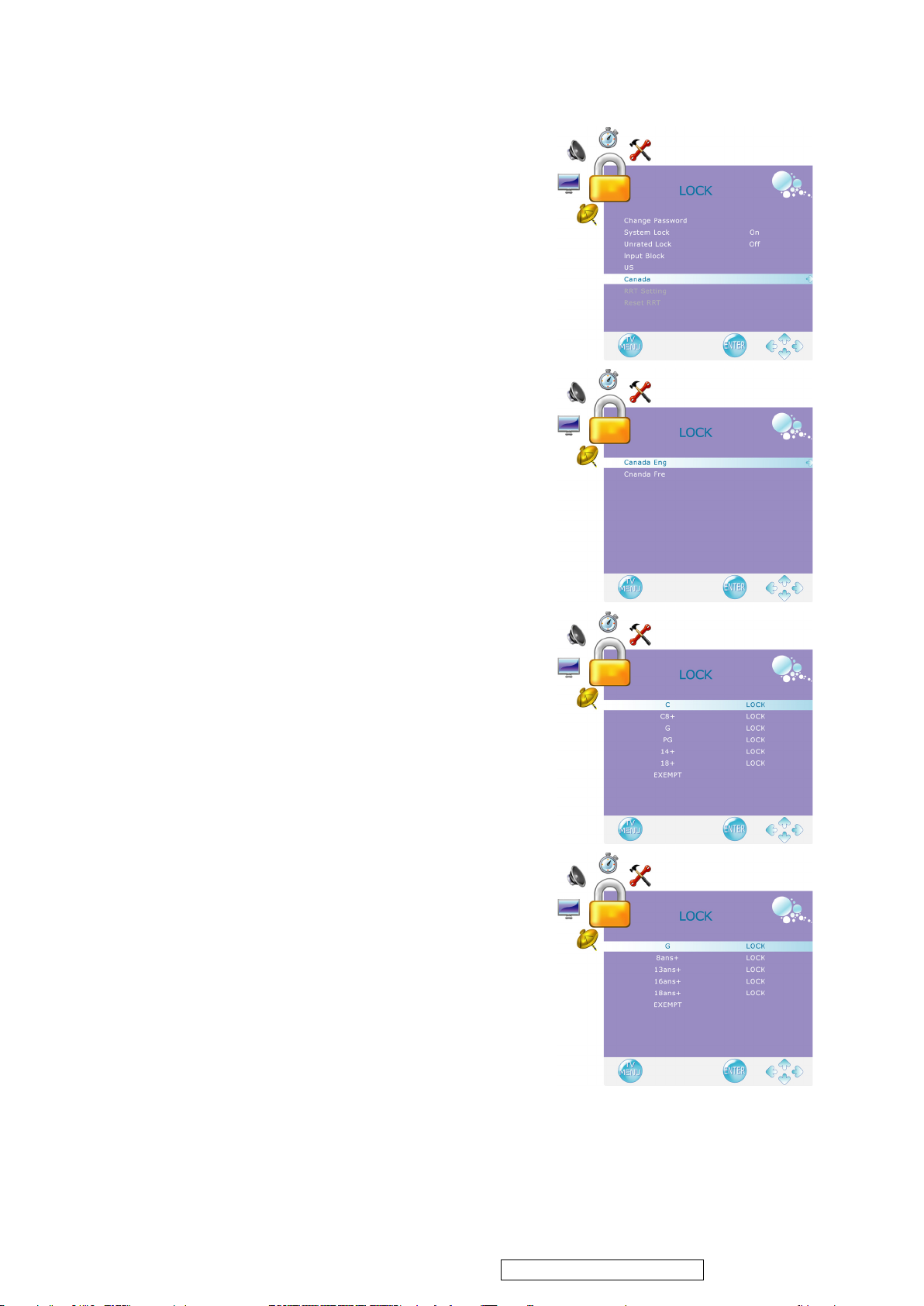
Canada: Press ► to set Canadian English and French
ratings.
(1) Canadian English
1. Press ▲ or ▼ to select “Canada Eng”.
2. Press ► to enter.
3. Press ▲ or ▼ to select your desired Canadian
English rating level.
The Canadian English rating levels are dened as
following:
C (children)
C8+ (children eight years and older)
G (general programming, suitable for all audiences)
PG (parental guidance)
14+ (viewers and older)
18+ (adult programming)
EXEMPT (exempt)
4. Press MENU to exit.
(2) Canadian French
1. Press ▲ or ▼ to select “Canada Fre”.
2. Press ► to enter.
3. Press ▲ or ▼ to select your desired Canadian
French rating level.
The Canadian French rating levels are dened as
following:
G (genenral)
8ans+ (children eight years and older)
13ans+ (not appropriate for children of less than 13
years)
16ans+ (not appropriate for children of less than 16
years)
18ans+ (reserved to adults)
EXEMPT (exempt)
4. Press MENU to exit.
Confidential - Do Not Copy
Page 28
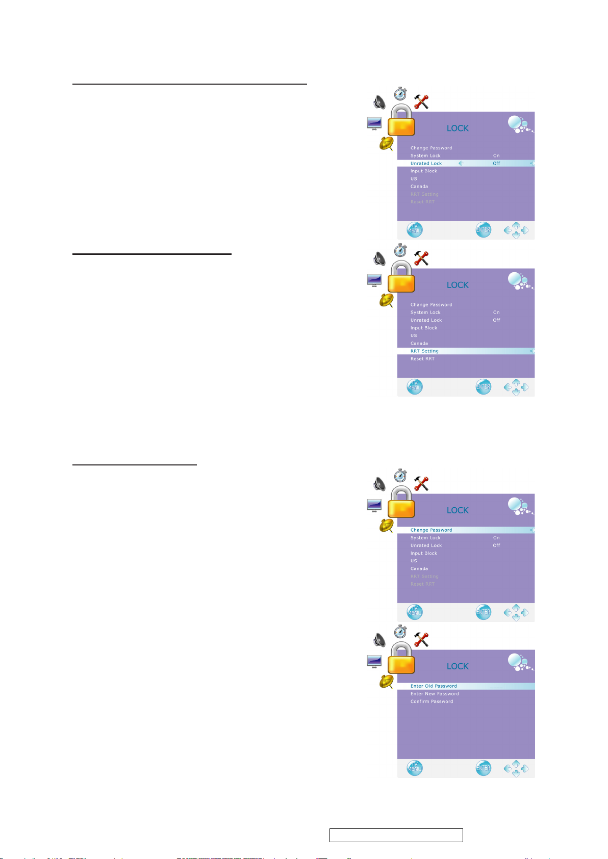
To Block Unrated Movie or TV Programs
ViewSonic Corporation
25
VT2430-1M
1. Press ▲ or ▼ to select “Unrated Lock”, then press ◄
or ► to select “On” or “Off”. When “On” is selected,
all programs that are not rated will be blocked.
2. Press MENU to exit.
To Set Rating Region Table
RRT Setting defines the rating standard for a particular
geographic region and/ or country.
1. Press ▲ or ▼ to select “RRT Setting”, then press ► to
enter RRT setting.
2. Select each adjustable setting with ▲ or ▼, then press
◄ or ► to select the sub-selection.
3. Press MENU to exit.
*The picture here only shows an example of the content
of RRT Setting. However, the selections and subselections of RRT Setting may be different in your OSD
menu according to the local broadcasting system.
*To reset RRT setting, move to “Reset RRT”, and press
► to reset.
ENGLISH
To Change Password
1. Press ▲ or ▼ to select “Change Password”, then press
► to enter “Change Password” setting.
2. Move to “Enter Old Password”, then enter the old
password with number keys.
3. Enter your new password on “Enter New Password”.
4. Enter your new password again on “Conrm Password”.
After you complete the last step, the screen will return to
the top page of LOCK menu. If so, the password has been
changed successfully.
Confidential - Do Not Copy
Page 29
ENGLISH
ViewSonic Corporation
26
VT2430-1M
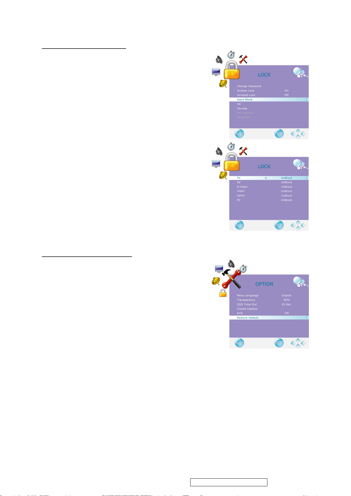
To block by Input Source
1. Press ▲ or ▼ to select “Input Block”.
2. Press ▲ or ▼ to select the input source, then ◄ or ►
to select from “Block” or “UnBlock”.
3. Press MENU to exit.
To Restore Factory Setting
1. Press the MENU button to display the OSD main menu.
2. Press ▲ or ▼ to select the “OPTION” menu.
3. Press ENTER or ► to enter “OPTION” menu.
4. Press ▲ or ▼ to select “Restore Default”, then press ►
to restore the factory default setting.
5. Select “Yes” and press ENTER to conrm the setting.
Confidential - Do Not Copy
Page 30
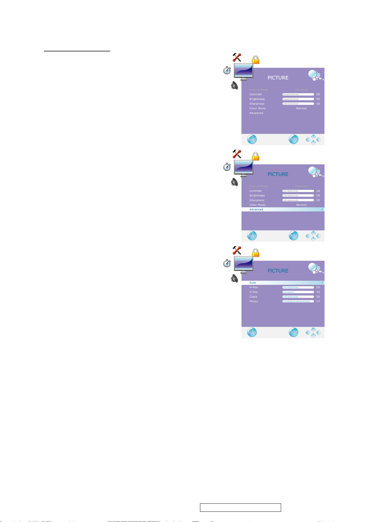
Using PC Function
ViewSonic Corporation
27
VT2430-1M
1. When in PC source, press the MENU button to display
the OSD main menu.
2. Press ◄ or ► to select the “PICTURE” menu.
3. Press ▲ or ▼ to select your desired controls, and press
◄ or ► to adjust.
4. For advanced PC functions, select “Advanced” (only
in PC source) and press ► to enter.
5. Press ▲ or ▼ to select “Auto” (Auto adjustment),
“H-Pos” (H-Position), “V-Pos” (V-Position), “Clock”
or “Phase”, and adjust the level with ◄ or ►.
*When in PC source, the other menus are the same as or
similar to when in other source.
*When there is no signal in the PC mode, “No Signal” will
be displayed on the screen and the TV will automatically
turn into power-saving mode after a few seconds’ idleness.
Press INPUT or POWER button on the remote control
and the TV will return to VGA mode.
ENGLISH
Notes:Initial password:0000
If you forget your initial password,you can press"3660"to resume.
"MENU" Lock & Un-lock: Pressing "CH+" and "CH-" from Front Panel Keys
"POWER" Lock & Un-lock: Pressing "Vol+" and "MENU" from Front Panel Keys
"BUTTON" Lock & Un-lock: Pressing "Vol+" and "Vol-" from Front Panel Keys
Confidential - Do Not Copy
Page 31

4. Circuit Description
ViewSonic Corporation
28
VT2430-1M
A/D converter
This brick convert is the 110-220AC input voltage to 24V output for inverter use and 5V for panel ,
system and audio use and 3.3V,1.8V for controller use.
INVERTER
In order to drive the CCFLs embedded in the panel module, there is a half bridge inverter to convert by
the controller.
The input 24V up to hundreds of AC voltage output.
The inverter is formed by symmetric in order to drive the separate lamp modules.
The input stage consists of a PWM controller, half bridge inverter, and switching MOSFET to convert
DC input into AC output.
The output stage consists of a tuning capacitor, coupling capacitor, transformer, push-pull MOSFET
pair to boost AC output up to hundreds of voltage.
And one resister is serial to lamp for output voltage feedback.
There are two signal to control the inverter which come from system.
Logic “high” level which send to I901 is turn on the inverter.
BRI signal control brightness by DC level which was integral from PWM signal.
I206 Scaler MSD2248AL
The MSD2248AL is a highly integrated controller IC for LCD/PDP DTV applications with resolutions
up to full-HD(1920 x 1080). It is configured with an integrated triple-ADC/PLL, a multi-standard TV
video and audio decoder, a motion adaptive video de-interlacer, a scaling engine, the MStarACE-3
color engine, an advanced 2D graphics engine, a transport processor, a high-definition (HD) MPEG
video decoder, a 24-bit DSP for MPEG audio decoding, a DVI/HDCP/HDMI receiver, and a peripheral
control unit providing a variety of HDTV control
functions.
The MSD2248AL comprises an MPEG-2 transport processor with advanced section filtering capability,
an MPEG-2 (MP@HL profile) video decoder, a DolbyDigital (AC-3)/MPEG layer I and II digital audio
decoder with analog audio outputs that are designed to support ATSC HD/SDTV programs while
handling ATSC CC and EPG.
With additional software support, the MSD2248AL can be used in DVB-T standard areas such as part
of Asia,Africa, and Australia. Furthermore, it is also possible to decode MPEG-4, JPEG, MP3 formats
from external sources such as USB interfaces.
For analog TV, the MSD2248AL includes NTSC/PAL/SECAM multi-standard video decoder
comprising a 3-D motion adaptive comb filter and time-based correction, and a BTSC/A2/EIA-J audio
decoder to support worldwide television standards. In addition, the MStar advanced LCD TV processor
enhances video quality,motion adaptive de-interlacer, picture quality adjustment units, and
MStarACE-3 color engine.
By integrating peripherals including USB 2.0 host controller, UART, IR, SPI, I2C, and PWM, the
MSD2248AL fulfills all requirements in advanced DTV sets.To further reduce system costs, the
MSD2248AL also integrates intelligent power management control capability for green-mode
requirements and spread-spectrum support for EMI management.
PIN DESCRIPTION
Analog Interface
Pin Name Pin Type Function Pin
VCLAMP CVBS/YC Mode Clamp Voltage Bypass 18
REFP Internal ADC Top De-coupling Pin 19
REFM Internal ADC Bottom De-coupling Pin 20
REXT Analog Input External Resister 390 ohm to AVDD_33 13
BIN1P Analog Input Analog Blue Input from Channel 1 21
SOGIN1 Analog Input Sync-On-Green input from Channel 1 22
GIN1P Analog Input Analog Green Input from Channel 1 23
RIN1P Analog Input Analog Red Input from Channel 1 24
BINM Analog Input Reference Ground for Analog Blue Input 25
BIN0P Analog Input Analog Blue Input from Channel 0 26
GINM Analog Input Reference Ground for Analog Green Input 27
Confidential - Do Not Copy
Page 32

GIN0P Analog Input Analog Green Input from Channel 0 28
ViewSonic Corporation
29
VT2430-1M
SOGIN0 Analog Input Sync-On-Green Input from Channel 0 29
RINM Analog Input Reference Ground for Analog Red Input 30
RIN0P Analog Input Analog Red Input from Channel 0 31
HSYNC1 Schmitt Trigger Input
w/ 5V-tolerant
HSYNC / Composite Sync for VGA Input from channel 1 16
VSYNC1 Schmitt Trigger Input
w/ 5V-tolerant
VSYNC for VGA Input from channel 1 17
HSYNC0 Schmitt Trigger Input
w/ 5V-tolerant
HSYNC / Composite Sync for VGA Input from channel 0 34
VSYNC0 Schmitt Trigger Input
w/ 5V-tolerant
VSYNC for VGA Input from channel 0 35
Analog Video Input/Output Interface
Pin Name Pin Type Function Pin
VCOM1 Analog Input CVBS Video Input Reference Ground 43
VCOM0 Analog Input CVBS Video Input Reference Ground 45
CVBS7 Analog Input CVBS (Composite) Video Input Channel 7 36
CVBS5 Analog Input CVBS (Composite) Video Input Channel 5 37
CVBS6 Analog Input CVBS (Composite) Video Input Channel 6 38
CVBS4 Analog Input CVBS (Composite) Video Input Channel 4 39
CVBS3 Analog Input CVBS (Composite) Video Input Channel 3 40
CVBS2 Analog Input CVBS (Composite) Video Input Channel 2 41
CVBS1 Analog Input CVBS (Composite) Video Input Channel 1 42
CVBS0 Analog Input CVBS (Composite) Video Input Channel 0 44
CVBSOUT Analog Output CVBS (Composite) Video Output 48
Analog Audio Input/Output Interface
Pin Name Pin Type Function Pin
SIF1P Analog Input SIF Audio Input Channel 1 51
SIF1M Analog Input Reference Ground for SIF Audio Input Channel 1 52
I2S_OUT_MCK Output Audio Master Clock Output 109
I2S_OUT_BCK Output Audio Bit Clock Output 110
I2S_OUT_WS Output Word Select Output; 4mA driving strength 108
I2S_OUT_SD Output Audio Serial Data Output; 4mA driving strength 111
I2S_OUT_MUTE Output Audio Output Mute Control 112
SPDIFO Output S/PDIF Audio Output; 4mA driving strength 107
I2S_IN_SD Input Audio Serial Data Input 105
SPDIFI Input S/PDIF Audio Input 106
AUVRM Analog Output Negative Reference Voltage for Audio ADC 67
AUVRP Analog Output Positive Reference Voltage for Audio ADC 68
AUVAG Analog Output Reference Voltage for Audio Common Mode 69
AUL0 Analog Input Audio Line Input Left Channel 0 55
AUR0 Analog Input Audio Line Input Right Channel 0 56
AUL1 Analog Input Audio Line Input Left Channel 1 57
AUR1 Analog Input Audio Line Input Right Channel 1 58
AUL2 Analog Input Audio Line Input Left Channel 2 59
AUR2 Analog Input Audio Line Input Right Channel 2 60
AUL3 Analog Input Audio Line Input Left Channel 3 61
AUR3 Analog Input Audio Line Input Right Channel 3 62
AUOUTL2 Analog Output Main Audio Output Left Channel 2 71
AUOUTR2 Analog Output Main Audio Output Right Channel 2 72
AUOUTL1 Analog Output Main Audio Output Left Channel 1 73
AUOUTR1 Analog Output Main Audio Output Right Channel 1 74
AUOUTL0 Analog Output Main Audio Output Left Channel 0 76
AUOUTR0 Analog Output Main Audio Output Right Channel 0 77
AUCOM Analog Input Reference Ground for Audio Line Input 63
TS Input Interface
Confidential - Do Not Copy
Page 33

Pin Name Pin Type Function Pin
ViewSonic Corporation
30
VT2430-1M
TSCLK Input w/ 5V-tolerant TS Clock 100
TSDATA[7:0] Input w/ 5V-tolerant TS Data in Parallel; LSB (bit 0) is for serial TS data 97-90
TSVALID Input w/ 5V-tolerant TS Data Valid 98
TSSYNC Input w/ 5V-tolerant TS Sync-Byte Indicator 99
DVI/HDMI Interface
Pin Name Pin Type Function Pin
RX0N Input DVI/HDMI Channel 0 Negative Data Input 4
RX0P Input DVI/HDMI Channel 0 Positive Data Input 5
RX1N Input DVI/HDMI Channel 1 Negative Data Input 7
RX1P Input DVI/HDMI Channel 1 Positive Data Input 8
RX2N Input DVI/HDMI Channel 2 Negative Data Input 10
RX2P Input DVI/HDMI Channel 2 Positive Data Input 11
RXCKN Input DVI/HDMI Negative Clock Input 2
RXCKP Input DVI/HDMI Positive Clock Input 3
LVDS Interface
Pin Name Pin Type Function Pin
LVA0M Output LVDS A-Link Channel 0 Negative Data Output 146
LVA0P Output LVDS A-Link Channel 0 Positive Data Output 145
LVA1M Output LVDS A-Link Channel 1 Negative Data Output 144
LVA1P Output LVDS A-Link Channel 1 Positive Data Output 143
LVA2M Output LVDS A-Link Channel 2 Negative Data Output 142
LVA2P Output LVDS A-Link Channel 2 Positive Data Output 141
LVACKM Output LVDS A-Link Negative Clock Output 140
LVACKP Output LVDS A-Link Positive Clock Output 139
LVA3M Output LVDS A-Link Channel 3 Negative Data Output 138
LVA3P Output LVDS A-Link Channel 3 Positive Data Output 137
LVB0M Output LVDS B-Link Channel 0 Negative Data Output 159
LVB0P Output LVDS B-Link Channel 0 Positive Data Output 158
LVB1M Output LVDS B-Link Channel 1 Negative Data Output 157
LVB1P Output LVDS B-Link Channel 1 Positive Data Output 156
LVB2M Output LVDS B-Link Channel 2 Negative Data Output 155
LVB2P Output LVDS B-Link Channel 2 Positive Data Output 154
LVBCKM Output LVDS B-Link Negative Clock Output 153
LVBCKP Output LVDS B-Link Positive Clock Output 152
LVB3M Output LVDS B-Link Channel 3 Negative Data Output 151
LVB3P Output LVDS B-Link Channel 3 Positive Data Output 150
Serial Flash Interface
Pin Name Pin Type Function Pin
SCK Output SPI Flash Serial Clock 129
SDI Output SPI Flash Serial Data Input 130
SDO Input w/ 5V-tolerant SPI Flash Serial Data Output 131
SCZ Output SPI Flash Chip Select 132
IRIN Input w/ 5V-tolerant IR Receiver Input 114
INT Input w/ 5V-tolerant MCU Bus Interrupt; 4mA driving strength 115
GPIO Interface
Pin Name Pin Type Function Pin
GPIO125 I/O w/ 5V-tolerant General Purpose Input/Output; 4mA driving strength 12
GPIO124 I/O General Purpose Input/Output; 4mA driving strength 135
GPIO123 I/O General Purpose Input/Output; 4mA driving strength 136
GPIO112 I/O General Purpose Input/Output; 4mA driving strength 148
GPIO111 I/O General Purpose Input/Output; 4mA driving strength 149
GPIO100 I/O General Purpose Input/Output; 4mA driving strength 164
GPIO99 I/O General Purpose Input/Output; 4mA driving strength 165
GPIO98 I/O General Purpose Input/Output; 4mA driving strength 166
GPIO97 I/O General Purpose Input/Output; 4mA driving strength 167
GPIO45/I2S_IN_BCK I/O General Purpose Input/Output; 4mA driving strength /
Audio Bit Clock Input 104
GPIO44/I2S_IN_WS I/O General Purpose Input/Output; 4mA driving strength /
Word Select Output; 4mA driving strength 103
Confidential - Do Not Copy
Page 34

GPIO28 I/O w/ 5V-tolerant General Purpose Input/Output; 4mA driving strength 87
ViewSonic Corporation
31
VT2430-1M
GPIO27 I/O w/ 5V-tolerant General Purpose Input/Output; 4mA driving strength 86
GPIO26 I/O w/ 5V-tolerant General Purpose Input/Output; 4mA driving strength 85
GPIO25 I/O w/ 5V-tolerant General Purpose Input/Output; 4mA driving strength 84
GPIO24 I/O w/ 5V-tolerant General Purpose Input/Output; 4mA driving strength 83
GPIO23 I/O w/ 5V-tolerant General Purpose Input/Output; 4mA driving strength 82
GPIO22 I/O w/ 5V-tolerant General Purpose Input/Output; 4mA driving strength 81
GPIO21 I/O w/ 5V-tolerant General Purpose Input/Output; 4mA driving strength 80
GPIO20 I/O w/ 5V-tolerant General Purpose Input/Output; 4mA driving strength 79
GPIO15/CEC I/O General Purpose Input/Output; 4mA driving strength / Consumer Electronics Control
134
GPIO14/UART_TX1 I/O General Purpose Input/Output; 4mA driving strength / Universal
Asynchronous Transmitter 196
GPIO13/UART_RX1/CEC I/O General Purpose Input/Output; 4mA driving strength /
Universal Asynchronous Receiver / Consumer Electronics Control 195
PWM3 Output Pulse Width Modulation Output; 4mA driving strength 125
PWM2 Output Pulse Width Modulation Output; 4mA driving strength 124
PWM1 Output Pulse Width Modulation Output; 4mA driving strength 123
PWM0 Output Pulse Width Modulation Output; 4mA driving strength 122
SAR3 Analog Input SAR Low Speed ADC Input 3; General Purpose Input/Output 121
SAR2 Analog Input SAR Low Speed ADC Input 2; General Purpose Input/Output 120
SAR1 Analog Input SAR Low Speed ADC Input 1; General Purpose Input/Output 119
SAR0 Analog Input SAR Low Speed ADC Input 0; General Purpose Input/Output 118
DRAM Interface
Pin Name Pin Type Function Pin
DQM[3:0] Output Data Mask for Low Byte; active high 177, 188, 231, 242
DQS[3:0] I/O Data Strobe 168, 192, 221, 246
MVREF Input Reference Voltage for DDR SDRAM Interface 197
MCLKZ Output DRAM Memory Negative Differential Clock 198
MCLK Output DRAM Memory Positive Differential Clock 199
MCLKE Output DRAM Memory Clock Enable 200
BADR[1:0] Output DRAM Memory Bank Address 216, 217
WEZ Output Write Enable; active low 218
RASZ Output Row Address Strobe; active low 219
CASZ Output Column Address Strobe; active low 220
MDATA[31:0] I/O DRAM Memory Data Bus 170, 171, 173-176,
178, 179, 181-186,
189, 190, 223, 224,
226-229, 232, 233,
235-240, 243, 244
MADR[12:0] Output DRAM Memory Address 215-210, 208-202
USB Interface
Pin Name Pin Type Function Pin
USB_REXT USB External Resistor Pin;Connected through 910 ohm (±1%) Resistor to GND
(Pin#253)249
USB_DM Analog I/O USB Inverting Data Input/Output 251
USB_DP Analog I/O USB Non Inverting Data Input/Output 252
Misc. Interface
Pin Name Pin Type Function Pin
DDCD_DA I/O w/ 5V-tolerant HDCP Serial Bus Data / DDC Data of DVI/HDMI Port 14
DDCD_CK Input w/ 5V-tolerant HDCP Serial Bus Clock / DDC Clock of DVI/HDMI Port 15
DDCA_DA I/O w/ 5V-tolerant DDC Data for Analog Port 116
DDCA_CK I/O w/ 5V-tolerant DDC Clock for Analog Port 117
HWRESET Schmitt Trigger Input w/ 5V-tolerant Hardware Reset; active high 128
DDCR_DA I/O w/ 5V-tolerant DDC Data for ROM 126
DDCR_CK I/O w/ 5V-tolerant DDC Clock for ROM 127
XIN Analog Input Crystal Oscillator Input 255
XOUT Analog Output Crystal Oscillator Output 254
Power Pins
Confidential - Do Not Copy
Page 35

Pin Name Pin Type Function Pin
ViewSonic Corporation
32
VT2430-1M
AVDD_SIF 3.3V Power SIF Power 50
AVDD_AU 3.3V Power Audio Power 70
AVDD_DDR 2.5V Power DDR Power 169, 180, 191, 209,
222, 234, 245
AVDD_LPLL 3.3V Power LPLL Power 160
AVDD_MPLL 3.3V Power MPLL Power 256
AVDD_MEMPLL 3.3V Power PLL Power 201
AVDD_33 3.3V Power ADC Power 6, 32, 46
AVDDL_DVI 1.2V Power DVI Power 248
AVDD_USB 3.3V Power USB Power 250
VDDC 1.2V Power Digital Core Power 53, 89, 102, 163,
194, 230, 247
VDDP 3.3V Power Digital Input/Output Power 78, 113, 133, 147
GND Ground Ground 1, 9, 33, 49, 54, 66,
88, 101, 161, 162,
172, 187, 193, 225,
241, 253
No Connects
Pin Name Pin Type Function Pin
NC No connect. 47, 64, 65, 75
I201,I212 PT5DU281620VP DDRAM (RA)
The PT5DU281620VP is a 134,217,728-bit CMOS Double Data Rate(DDR) Synchronous DRAM,
ideally suited for the main memory applications which requires large memory density and high
bandwidth.
This Wins 128Mb DDR SDRAMs offer fully synchronous operations referenced to both rising and
falling edges of the clock. While all addresses and control inputs are latched on the rising edges of the
CK (falling edges of the /CK), Data, Data strobes and Write data masks inputs are sampled on both
rising and falling edges of it. The data paths are internally pipelined and 2-bit prefetched to achieve
very high bandwidth. All input and output voltage levels are compatible with SSTL_2.
I201,I212 HYB25DC256163CE-4 DDR1 (16Mx16) (RB)
The 256-Mbit Double-Data-Rate SGRAM is a high-speed CMOS, dynamic random-access memory
containing 268,435,456 bits. It is internally configured as a quad-bank DRAM.
The 256-Mbit Double-Data-Rate SGRAM uses a double-data-rate architecture to achieve high-speed
operation. The doubledata- rate architecture is essentially a 2n prefetch architecture with an interface
designed to transfer two data words per clock cycle at the I/O pins. A single read or write access for the
256-Mbit Double-Data-Rate SGRAM effectively consists of a single 2n-bit wide, one clock cycle data
transfer at the internal DRAM core and two corresponding n-bit wide, one-half-clock-cycle data
transfers at the I/O pins.
A bidirectional data strobe (DQS) is transmitted externally, along with data, for use in data capture at
the receiver. DQS is a strobe transmitted by the DDR SGRAM during Reads and by the memory
controller during Writes. DQS is edge-aligned with data for Reads and center-aligned with data for
Writes.
The 256-Mbit Double-Data-Rate SGRAM operates from a differential clock (CK and CK; the crossing
of CK going HIGH and CK going LOW is referred to as the positive edge of CK). Commands (address
and control signals) are registered at every positive edge of CK. Input data is registered on both edges
of DQS, and output data is referenced to both edges of DQS, as well as to both edges of CK.Read and
write accesses to the DDR SGRAM are burst oriented; accesses start at a selected location and continue
for a programmed number of locations in a programmed sequence. Accesses begin with the registration
of an Active command, which is then followed by a Read or Write command. The address bits
registered coincident with the Active command are used to select the bank and row to be accessed. The
address bits registered coincident with the Read or Write command are used to select the bank and the
starting column location for the burst access.
The DDR SGRAM provides for programmable Read or Write burst lengths of 2, 4 or 8 locations. An
Auto Precharge function may be enabled to provide a self-timed row precharge that is initiated at the
end of the burst access. As with standard SDRAMs, the pipelined, multibank architecture of DDR
SGRAMs allows for concurrent operation, thereby providing high effective bandwidth by hiding row
precharge and activation time.
Confidential - Do Not Copy
Page 36

An auto refresh mode is provided along with a power-saving power-down mode. All inputs are
ViewSonic Corporation
33
VT2430-1M
compatible with the Industry Standard for SSTL_2. All outputs are SSTL_2, Class II compatible.
Note: The functionality described and the timing specifications included in this data sheet are for the
DLL Enabled mode of operation.
I501 T uner
The Antenna receive the TV signal and modulate it to the CVBS signal and ATSC signal which can be
recognized By the decoder and MTS audio signal output to the sound multiplexing decoder portion of
IC MSD2248AL
I601 YDA148 AUDIO AMP
YDA148 (D-510) is a high-efficiency digital audio power amplifier IC with the maximum output of
15W × 2ch.
YDA148 has a “Pure Pulse Direct Speaker Drive Circuit” that directly drives speakers while reducing
distortion of pulse output signal and reducing noise on the signal, which realizes the highest standard
low distortion rate characteristics and low noise characteristics among digital amplifier ICs in the same
class.
In addition, supporting filterless design allows circuit design with fewer external parts to be realized
depending on use conditions.
YDA148 features Power Limit Function, Non-clip Function, and DRC (Dynamic Range Control)
Function that were developed by Yamaha original digital amplifier technology.
YDA148 has overcurrent protection function for speaker output terminals, high temperature protection
function, and lowsupply voltage malfunction prevention function.
I601 TPA6113A2
The TPA6113A2 is a stereo audio power amplifier packaged in an 8-pin SOIC package capable of
delivering 40mW of continuous RMS power per channel into 16-Ω loads Amplifier gain is extermally
configured by means of two resistors per input channel and does not require external compensation for
settings of 0 to 20 dB.
I202 MSD809
The MSD809 is a DTV receiver, which contains a digital receiver compatible with ATSC 8-VSB mode
for terrestrial broadcasting and open cable (SCTE DVS-031) which is in compliant with 64-QAM and
256-QAM modes for digital cable appliances.
It achieves extremely high performance employing direct IF sampling architecture,robust
synchronization, and robust channel equalization. It contains a 12-bit A/D converter and a PWM
generator for automatic gain control. A host interface with an I2C bus is also included to control the
behavior of the MSD809.
Confidential - Do Not Copy
Page 37
5. Adjusting Procedure
ViewSonic Corporation
34
VT2430-1M
5.1. ADJUSTMENT CONDITIONS AND PRECAUTIONS
1. Approximately 30 minutes should be allowed for warm up before proceeding.
2. Adjustments should be undertaken only on those necessary elements since most of them
have been carefully preset at the factory.
3. ESD protection is needed before adjustment.
5.2. MAIN ADJUSTMENTS
NO. FUNCTION DESIGNATION
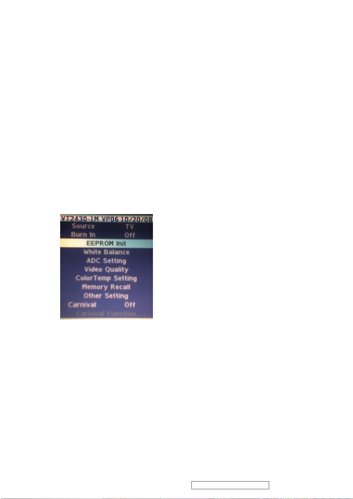
1. EEPROM Initial Function Key
2. Adjust color temperature
5.3. ALIGNMENT PROCEDURES
Adjustment Conditions and Precautions:
(A). Power supply voltage:AC 110V± 10% 50 Hz ± 5%.
(B). Warm up time:
The display must be power ON for at least 30 minutes at full white pattern before
starting alignments.
This is especially critical in color temperature and white balance adjustments.
(C). Video : reference the front detail specifications.
1. Eeprom Initial:
Press “ MENU ”and “▲” and “POWER” key go to factory mode.
Function Key
2. Adjust color temperature
A. Enter to the factory mode, Source select “ D_Sub” figure 2, Use 19200x1080@60Hz the pattern
is “ 5 block ” figure 1,then move the cursor to the White Balance figure 3. Press “►” key. That will
do auto white balance.
B. After auto white balance, switch to the full white pattern then check the color temperature.
WARM x=0.335 ± 0.03 y=0.350 ± 0.03
NORMAL x=0.313 ± 0.03 y=0.329 ± 0.03
COOL x=0.283 ± 0.03 y=0.298 ± 0.03
C. Enter to the factory mode, Source select “ YPbPr ”, Use NTSC Color Bar (FLUKE 54200 )
Figure 4, Set Color bar to 100 IRE then move the cursor to the White Balance figure 5. Press “►”
Key figure 6. That will do auto white balance. Finally change 16 gray scale must be claire in each
grays.
Confidential - Do Not Copy
Page 38
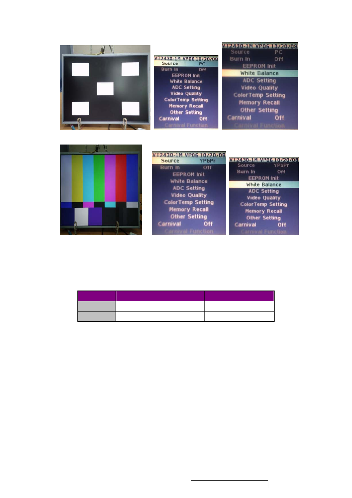
figure 1 figure 2 figure 3
ViewSonic Corporation
35
VT2430-1M
figure 4 figure 5 figure 6
3. Power Consumption Check ( VGA MODE )
A. TIMING: 1920 x 1080@60Hz
B. Pattern: 1010UPRIGHTNESS PATTERN
C. BRIGHTNESS=MAX, CONTRAST=MAX.
D. The power that each MODE consumed is shown in Chart 1.
MODE
NORMAL
Stand-by
4. Check the position of the picture displayed and phase auto adjusting (VGA MODE).
Depend on the TIMING of TIMING TABLE (TABLE 4) to switch MODE in order, stay about 10
seconds each MODE, it can changed and stored automatically each MODE. We can’t switch over
to the next MODE until AUTO ADJUST disappears.
5. HDMI MODE FUNCTION TEST
A.DVI MODE: Depend on the TIMING of TIMING TABLE (TABLE 3 ) to check MODE in
order.
B.HDMI MODE: make sure the 480i, 480p, 720p, 1080i,1080p TIMING is right.
6. OSD FUNCTION TEST
Time:1920*1080@60Hz
Pattern: 16*12 pane
Make sure that Each FUNCTION has one right action.
MAX POWER COMSUMED POWER LED COLOR
75W(max) BLUE
2W (max) ORANGE
Chart 1
Confidential - Do Not Copy
Page 39

7. DTV FUNCTION TEST
ViewSonic Corporation
36
VT2430-1M
Both NTSC and ATSC system were mixed together. At this point in tuner to the joints on the need
for 'AIR NTSC and ATSC 2 both systems were mixed with the signal
Both CATV and DIGITAL CABLE two systems are mixed together. At this point in tuner to the
need for a joint 'CATV and DIGITAL CABLE two systems are mixed in a the signal
8. YPbPr, S-VIDEO, AV, TV, DTV’S FUNCTION TEST
A. Input YPbPr, S-VIDEO, AV , TV, DTV’S signal and check.
B. Input USA air channel (TABLE 1) and USA CATV channel for TV channel.
Under YPbPr MODE, Make sure the 408i, 480P, 720P, 1080i,1080p is right.
9. AUDIO FUNCTION TEST
A. Audio input includes PC AUDIO IN, S-VIDEO/AV AUDIO IN and YPbPr/DVI AUDIO IN.
B. Under PC MODE, input PC AUDIO signal, checks whether the action of AUDIO IN is right.
C. Under S-VIDEO/AV MODE, input L/R AUDIO signal, checks whether the action of AUDIO
IN is right.
D. Under YPbPr MODE, input L/R AUDIO signal, checks whether the action of AUDIO IN is
right.Under HDMI MODE, checks whether the action of AUDIO IN is right Under TV MODE,
checks whether the action of AUDIO IN is right.
E. In DTV mode, the input signal ATSC, confirmed AUDIO LANGUAGE and the normal
movements PARENT
10.Under PC MODE, input PC AUDIO signal, determines whether the action of INT SPEAKER
output is right. Meets earphone with the EARPHONE, Determined whether the action of
EARPHONE output is normal.
11.DDC EDID confirm
VGA EDID confirm
By P502 VGA CONNECTOR DOWNLOAD EDID confirm whether normal or not
HDMI EDID confirm
By P501 HDMI CONNECTORS DOWNLOAD EDID confirm whether normal or not
12.All Modes Reset
After final QC step, we must to erase all saved changes again and restore the factory defaults.
You should do “memory recall ” again.
Turn off the LCD TV by pressing “Power” button
13.BURN IN Mode access methods
Key Pad followed by pressing the "MENU" + "INPUT" 2 KEY, entered BURN IN mode
14.DCR function confirm In all source. (VT2430-1M model only)
A. DCR turn ON.
B. Input full white pattern then measure the luminance. For example Value A
C. Input full dark pattern the measure the luminace. For example Value B
D. These two value ratio must be more than 10000. (A/B).
Confidential - Do Not Copy
Page 40
TV Frequency Table:
ViewSonic Corporation
37
VT2430-1M
U.S.A Channel (TABLE 1)
VIF 45.75 MHz, SIF 41.25 MHz
(Unit:MHz)
Ch. Freq.range fp (picture) fs (sound) fosc Ch. Freq.range fp (picture) fs (sound) fosc
2
3
4
5
6
7
8
9
10
11
12
13
14
15
16
17
18
19
20
21
22
23
24
25
26
27
28
29
30
31
32
33
34
35
36
37
38
39
40
41
42
54 – 60
60 – 66
66 – 72
76 – 82
82 – 88
174 – 180
180 – 186
186 – 192
192 – 198
198 – 204
204 – 210
210 – 216
470 – 476
476 – 482
482 – 488
488 – 494
494 – 500
500 – 506
506 – 512
512 – 518
518 – 524
524 – 530
530– 536
536 – 542
542 – 548
548 – 554
554 – 560
560 – 566
566 – 572
572 – 578
578 – 584
584 – 590
590 – 596
596 – 602
602 – 608
608 – 614
614 – 620
620 – 626
626 – 632
632 – 638
639 – 644
55.25
61.25
67.25
77.25
83.25
175.25
181.25
187.25
193.25
199.25
205.25
211.25
471.25
477.25
483.25
489.25
495.25
501.25
507.25
513.25
519.25
525.25
531.25
537.25
543.25
549.25
555.25
561.25
567.25
573.25
579.25
585.25
591.25
597.25
603.25
609.25
615.25
621.25
627.25
633.25
639.25
59.75
65.75
71.75
81.75
87.75
179.75
185.75
191.75
197.75
203.75
209.75
215.75
475.75
481.75
487.75
493.75
499.75
505.75
511.75
517.75
523.75
529.75
535.75
541.75
547.75
553.75
559.75
565.75
571.75
577.75
583.75
589.75
595.75
601.75
607.75
613.75
619.75
625.75
631.75
637.75
643.75
101.00
107.00
113.00
123.00
129.00
221.00
227.00
233.00
239.00
245.00
251.00
257.00
517.00
523.00
529.00
535.00
541.00
547.00
553.00
559.00
565.00
571.00
577.00
583.00
589.00
595.00
601.00
607.00
613.00
619.00
625.00
631.00
637.00
643.00
649.00
655.00
661.00
667.00
673.00
679.00
685.00
43
44
45
46
47
48
49
50
51
52
53
54
55
56
57
58
59
60
61
62
63
64
65
66
67
68
69
644 – 650
650 – 656
656 – 662
662 – 668
668 – 674
674 – 680
680 – 686
686 – 692
692 – 698
698 – 704
704 – 710
710 – 716
716 – 722
722 – 728
728 – 734
734 – 740
740 – 746
746 – 752
752 – 758
758 – 764
764 – 770
770 – 776
776 – 782
782 – 788
788 – 794
794 – 800
800 – 806
645.25
651.25
657.25
663.25
669.25
675.25
681.25
687.25
693.25
699.25
705.25
711.25
717.25
723.25
729.25
735.25
741.25
747.25
753.25
759.25
765.25
771.25
777.25
783.25
789.25
795.25
801.25
649.75
655.75
661.75
667.75
673.75
679.75
685.75
691.75
697.75
703.75
709.75
715.75
721.75
727.75
733.75
739.75
745.75
751.75
757.75
763.75
769.75
775.75
781.75
787.75
793.75
799.75
805.75
691.00
697.00
703.00
709.00
715.00
721.00
727.00
733.00
739.00
745.00
751.00
757.00
763.00
769.00
775.00
781.00
787.00
793.00
799.00
805.00
811.00
817.00
823.00
829.00
835.00
841.00
847.00
Confidential - Do Not Copy
Page 41
U.S.A. CATV (TABLE 2)
ViewSonic Corporation
38
VT2430-1M
VIF 45.75 MHz, SIF 41.25 MHz
Ch. Freq.range fp
(picture)
2
3
4
5A
5
6
A-5
A-4
A-3
A-2
A-1
A
B
C
D
E
F
G
H
I
7
8
9
10
11
12
13
J
K
L
M
N
O
P
Q
R
S
T
U
V
W
AA
BB
CC
DD
EE
FF
GG
HH
II
2
54 – 60
3
60 – 66
4
66 – 72
1
72 – 78
5
76 – 82
6
82 – 88
95
90 – 96
96
96 – 102
97
102 – 108
98
108 – 114
99
114 – 120
14
120 – 126
15
126 – 132
16
132 – 138
17
138 – 144
18
144 – 150
19
150 – 156
20
156 – 162
21
162 – 168
22
168 – 174
7
174 – 180
8
180 – 186
9
186 – 192
10
192 – 198
11
198 – 204
12
204 – 210
13
210 – 216
216 – 222
23
222 – 228
24
228 – 234
25
234 – 240
26
240 – 246
27
246 – 252
28
252 – 258
29
258 – 264
30
264 – 270
31
270 – 276
32
276 – 282
33
282 – 288
34
288 – 294
35
294 – 300
36
300 – 306
37
306 – 312
38
312 – 318
39
318 – 324
40
324 – 330
41
330 – 336
42
336 – 342
43
342 – 348
44
348 – 354
45
55.25
61.25
67.25
73.25
77.25
83.25
91.25
97.25
103.25
109.25
115.25
121.25
127.25
133.25
139.25
145.25
151.25
157.25
163.25
169.25
175.25
181.25
187.25
193.25
199.25
205.25
211.25
217.25
223.25
229.25
235.25
241.25
247.25
253.25
259.25
265.25
271.25
277.25
283.25
289.25
295.25
301.25
307.25
313.25
319.25
325.25
331.25
337.25
343.25
349.25
(Unit:MHz)
fs (sound) fosc Ch. Freq.range fp
(picture)
59.75
65.75
71.75
77.75
81.75
87.75
95.75
101.75
107.75
113.75
119.75
125.75
131.75
137.75
143.75
149.75
155.75
161.75
167.75
173.75
179.75
185.75
191.75
197.75
203.75
209.75
215.75
221.75
227.75
233.75
239.75
245.75
251.75
257.75
263.75
269.75
275.75
281.75
287.75
293.75
299.75
305.75
311.75
317.75
323.75
329.75
335.75
341.75
347.75
353.75
101.00
107.00
113.00
119.00
123.00
129.00
137.00
143.00
149.00
155.00
161.00
167.00
173.00
179.00
185.00
191.00
197.00
203.00
209.00
215.00
221.00
227.00
233.00
239.00
245.00
251.00
257.00
263.00
269.00
275.00
281.00
287.00
293.00
299.00
305.00
311.00
317.00
323.00
329.00
335.00
341.00
347.00
353.00
359.00
365.00
371.00
377.00
383.00
389.00
395.00
JJ
KK
LL
MM
NN
OO
PP
QQ
RR
SS
TT
UU
VV
WW
AAA
BBB
CCC
DDD
EEE
46
47
48
49
50
51
52
53
54
55
56
57
58
59
60
61
62
63
64
65
66
67
68
69
70
71
72
73
74
75
76
77
78
79
80
81
82
83
84
85
86
87
88
89
90
91
92
93
94
354 –360
360 –366
366 –372
372 –378
378 –384
384 –390
390 –396
396 –402
402 –408
408 –414
414 –420
420 –426
426 –432
432 –438
438 –444
444 –450
450 –456
456 –462
462 –468
468 –474
474 –480
480 –486
486 –492
492 –498
498 –504
504 –510
510 –516
516 –522
522 –528
528 –534
534 –540
540 –546
546 –552
552 –558
558 –564
564 –570
570 –576
576 –582
582 –588
588 –594
594 –600
600 –606
606 –612
612 –618
618 –624
624 –630
630 –636
636 –642
642 –648
355.25
361.25
367.25
373.25
379.25
385.25
391.25
397.25
403.25
409.25
415.25
421.25
427.25
433.25
439.25
445.25
451.25
457.25
463.25
469.25
475.25
481.25
487.25
493.25
499.25
505.25
511.25
517.25
523.25
529.25
535.25
541.25
547.25
553.25
559.25
565.25
571.25
577.25
583.25
589.25
595.25
601.25
607.25
613.25
619.25
625.25
631.25
637.25
643.25
fs
(sound)
359.75
365.75
371.75
377.75
383.75
389.75
395.75
401.75
407.75
413.75
419.75
425.75
431.75
437.75
443.75
449.75
455.75
461.75
467.75
473.75
479.75
485.75
491.75
497.75
503.75
509.75
515.75
521.75
527.25
533.75
539.75
545.75
551.75
557.75
563.75
569.75
575.75
581.75
587.75
593.75
599.75
605.75
611.75
617.75
623.75
629.75
635.75
641.75
647.75
fosc
401.00
407.00
413.00
419.00
425.00
431.00
437.00
443.00
449.00
455.00
461.00
467.00
473.00
479.00
485.00
491.00
497.00
503.00
509.00
515.00
521.00
527.00
533.00
539.00
545.00
551.00
557.00
563.00
569.00
575.00
581.00
587.00
593.00
599.00
605.00
611.05
617.00
623.00
629.00
635.00
641.00
647.00
653.00
659.00
665.00
671.00
677.00
693.00
689.00
Confidential - Do Not Copy
Page 42
DIGITAL CABLE TV Frequence Table (table 3)
ViewSonic Corporation
39
VT2430-1M
U.S.A Channel Frequency Assignments (Cable)
unit:MHz.
CH NO. DTV Center Freq CH NO. DTV Center Freq CH NO. DTV Center Freq
2 57 43 339 84 585
3 63 44 345 85 591
4 69 45 351 86 597
5 79 46 357 87 603
6 85 47 363 88 609
7 177 48 369 89 615
8 183 49 375 90 621
9 189 50 381 91 627
10 195 51 387 92 633
11 201 52 393 93 639
12 207 53 399 94 645
13 213 54 405 95 93
14 223 55 411 96 99
15 129 56 417 97 105
16 135 57 423 98 111
17 141 58 429 99 117
18 147 59 435 100 651
19 153 60 441 101 657
20 159 61 447 102 663
21 165 62 453 103 669
22 171 63 459 104 675
23 219 64 465 105 681
24 225 65 471 106 687
25 231 66 477 107 693
26 237 67 483 108 699
27 243 68 489 109 705
28 249 69 495 110 711
29 255 70 501 111 717
30 261 71 507 112 723
31 267 72 513 113 729
32 273 73 519 114 735
33 279 74 525 115 741
34 285 75 531 116 747
35 291 76 537 117 753
36 297 77 543 118 759
37 303 78 549 119 765
38 309 79 555 120 771
39 315 80 561 121 777
40 321 81 567 122 783
41 327 82 573 123 789
42 333 83 579 124 795
Confidential - Do Not Copy
Page 43

TTV receiving test:
ViewSonic Corporation
40
VT2430-1M
TV SIGNAL TEST ITEM
CENTRALISM TRANSMITTING SIGNAL CHECK CONTENT
CHANNEL
ORDER
CHANNEL 2
CHANNEL 6
CHANNEL 7
CHANNEL 13
CHANNEL 14
CHANNEL 36
CHANNEL 69
TV TEST METHOD
A.CHANNEL2 Examines sound by ear, whether the sound does have mechanical resonation and
the electrical unusual sound, and image to sound disturbance.
B.CHANNEL6: Check sound and picture.
C.CHANNEL7: Examines whether the sound does receive the image disturbance, Judgment basis:
Whether there is unusual sound, input signal LEVEL<=36dBu,and STEREO SENSITIVITY is
normal.
D.CHANNEL13: Under main/sub/main-sub mode, check sub function.
E.CHANNEL14: Examines whether the sound does receive the image disturbance, Judgment basis:
Whether there is unusual sound.
F. CHANNEL 36:Check T1 of close-caption. Input signal level<=45dBu.
G.CHANNEL 69: Adjustment attenuator, If the critical point of the change of the image signal to
noise ratio is under LEVEL<=60dBu, regards as normally.
PRODUCTS OUTPUT CHECK ITEM.
The same as " CENTRALISM TRANSMITTING SIGNAL CHECK CONTENT"
saturation TEST, inputs the TV signal, the input signal LEVEL establishment most greatly is
90dBu,check whether CONTRAST of the image is normal; Whether appears the disturbance
phenomenon.
C.AFT CHECK,
(1) The frequency of the input TV signal is 211.25MHz (CH13), after confirmed the TV set
receives this signal, closure radio station; Then set frequency of the TV signal generator to be
212.25MHz, turn on the TV set and check whether the TV set receives the signal of CH13.
(2). The frequency of the input TV signal is 211.25MHz (CH13), after confirmed the TV set
receives this signal, closure radio station; Then set frequency of the TV signal generator to be
212.00MHz, turn on the TV set and check whether the TV set receives the signal of CH13.
(3). After all of FUNCTION TEST completed, we must erase all saved changes again and restore
the factory defaults.
DTV TEST ITEM
FREQUENCY
(MHz)
55.25 MONO SCOPE SWEEP TONE -10
83.25 COLOR BAR 400Hz -10 SOUND ,PICTURE
175.25 Full White (100
211.25 STAIR DUAL -10
471.25 MULTIBURST MONO -16
603.25 MULTIBURST MONO -10 TEST Close-caption T1
801.25 MONO SCOPE MONO(1KHz) -10 NOISE LIMMITTED
PATTERN SOUND P/S(dB)
SET CONTENT
STEREO -10
IRE)
CHECK
CONTENT
ELECTRIC
ABNORMITY
SOUND
STERO FUNCTION
SUB FUNCTION
IMAGE AND
SOUND DISTURB
FUNCTION
SENSITIVITY
CHANNEL FREQUENCY SOUND dB PETTEN CHECK CONTENT
14 471.25MHz Y 50
36 603.25MHz Y 50 Color bar Color
69 801.25MHz Y 75
Dynamic
picture
Dynamic
picture
Picture
Sound and Picture
Confidential - Do Not Copy
Page 44
ViewSonic Corporation
41
VT2430-1M
DTV CHECK METHOD
A.CHANNEL14: Check whether there are some pause or the mosaic phenomenon in the picture.
B.CHANNEL36: Check whether the color of the color bar is normal.
C.CHANNEL69: Turn RF attenuator and check the critical point of the change of the image’s S/N
is under LEVEL<45~85> dBu, regards as normally.
TIMING TABLE (FACTORY PRESET MODE) (table 4)
No Resolution V-freq
1 1920x1080 60 YES NO NO
2 1680x1050 59.8 YES NO NO
60 YES NO NO
3 1440x900 59.8 YES NO NO
59.9 YES NO NO
4 1280x1024 60 YES NO NO
75 YES NO NO
5 1024x768 60 YES YES YES
75 YES NO NO
6 832x624 75 YES YES YES
7 800x600 60 YES YES YES
75 YES YES YES
8 640x480 60 YES YES YES
75 YES YES YES
9 720x400 70 YES YES YES
D-SUB DVI TO HDMI HDMI
Confidential - Do Not Copy
Page 45
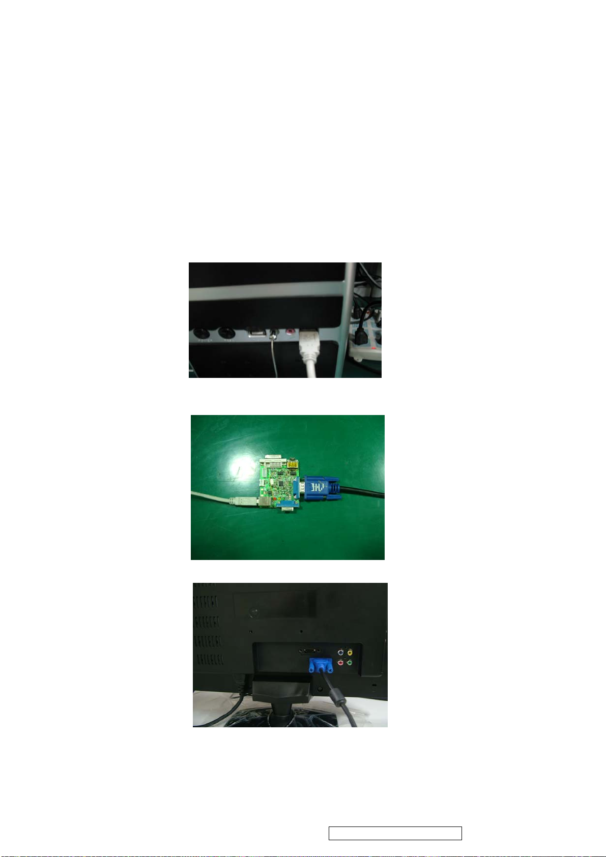
5. 4 Firmware Upgrade Procedure
ViewSonic Corporation
42
VT2430-1M
When you receive the returned LCD TV, please check whether the firmware version is the
latest. If not, please do the following procedures to upgrade it to the latest version.
5.4.1 Equipment Needed
- VT24301M LCD TV
- Fixture for Firmware Upgrade
- VGA Cable
- PC (Personal Computer)
- Firmware Upgrade Program
- One additional LCD TV for checking the program execution
5.4.2 Connection PC to the Tv set by the tool as the follow picture (pc1~pc3)
Action: The D_SUB cable must be 15 pin, and the TV set must be AC ON
pc.1
pc 2
pc 3
Confidential - Do Not Copy
Page 46
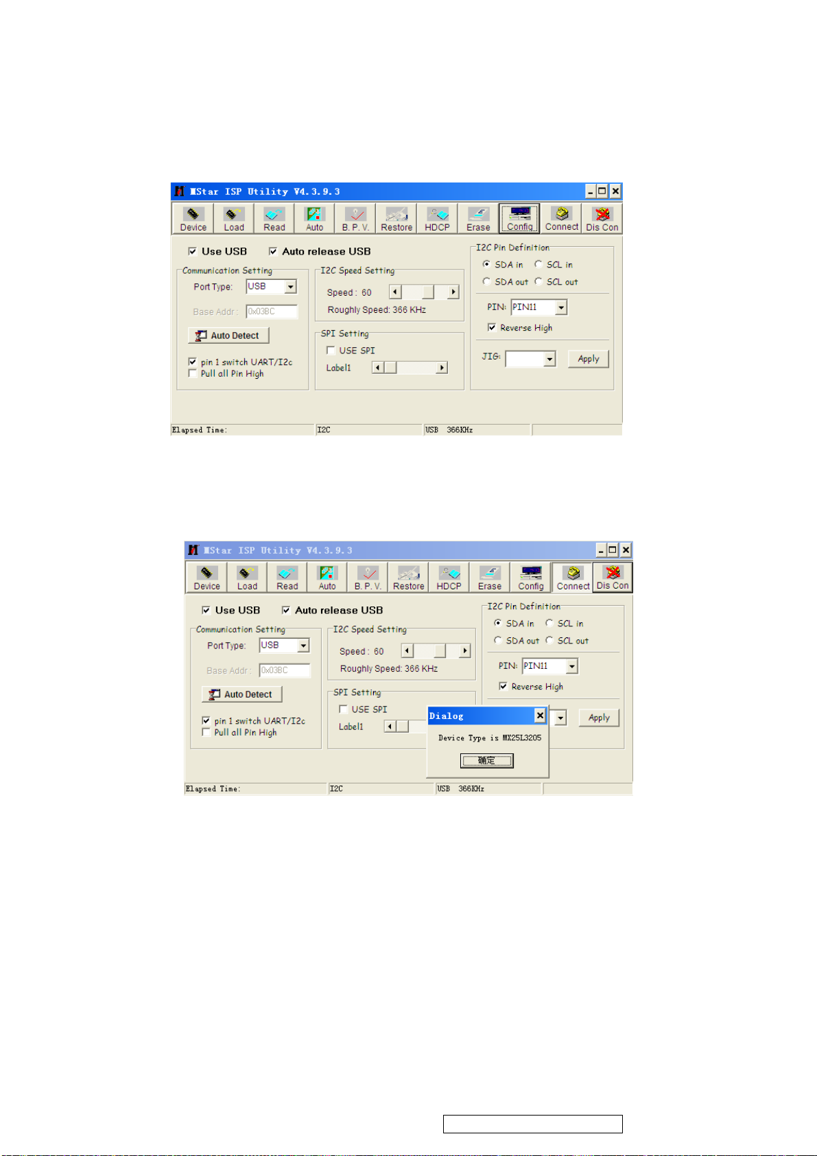
5.4.3 Start the Isp
ViewSonic Corporation
43
VT2430-1M
1. Open the “I.exe”
2. Press the “config” , if the the ISP board have been found ,you will see the picture as
bellow.
pc.4
3. Press the “Connect” ,If all the things are ok and ready, it will show the device type as
the bellow picture. Than pres “確定”
pc.5
Confidential - Do Not Copy
Page 47
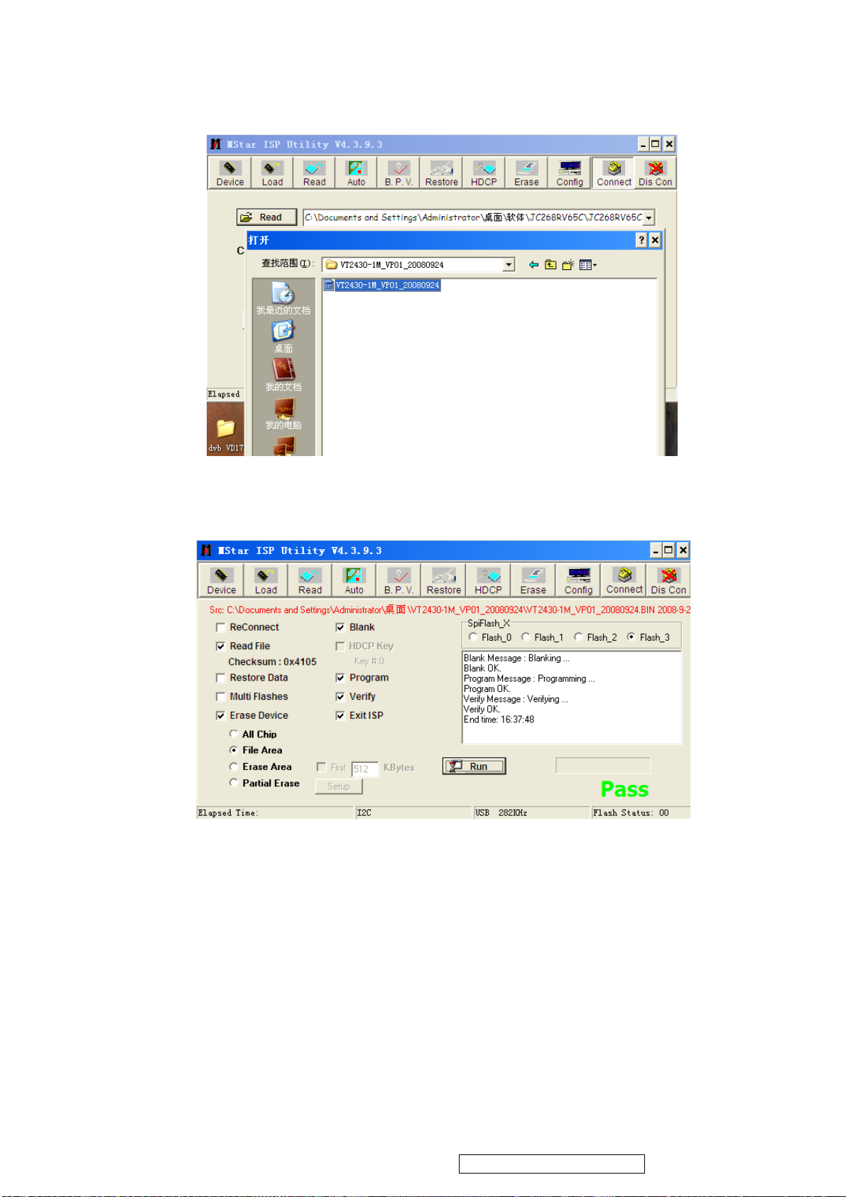
4. Press “read” and choose the right F/W .
ViewSonic Corporation
44
VT2430-1M
pc.6
5. Press “Auto”, than press “Run”. It will start ISP . When the ISP is ok ,you will see the
information as the bellow picture.
pc.7
6. Pull away the AC power Cord and the D-SUB Cable. And start another TV set.
When we start another TV set with AC ON, we only need to press the “RUN”
Confidential - Do Not Copy
Page 48
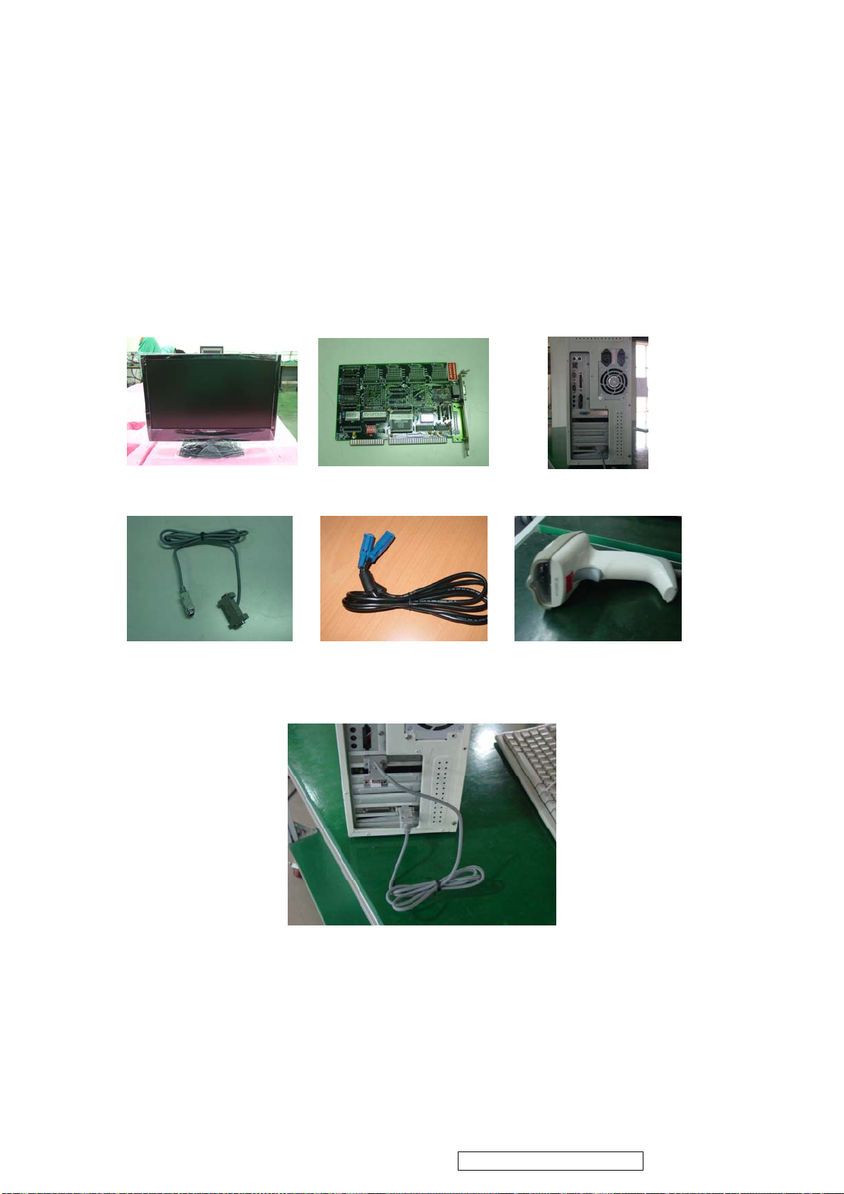
5.5 VGA DDC Key In Procedure
ViewSonic Corporation
45
VT2430-1M
Note:
1. Every time after replacing the main board, you have to do the DDC key in.
2. If you find the DDC does not conform to the LCD TV, you have to do the DDC key in.
5.5.1 Equipment Needed
- VT2430-1M LCD TV
- DDC Card
- PC
- RS-232 cable
- Barcode Reader
- VGA Cable
VT2430-1M LCD TV DDC Card PC
RS-232 Cable VGA Cable Barcode Reader
5.5.2 Setup Procedure
1. Connect VGA Card and DDC Card with RS-232 cable.
Confidential - Do Not Copy
Page 49
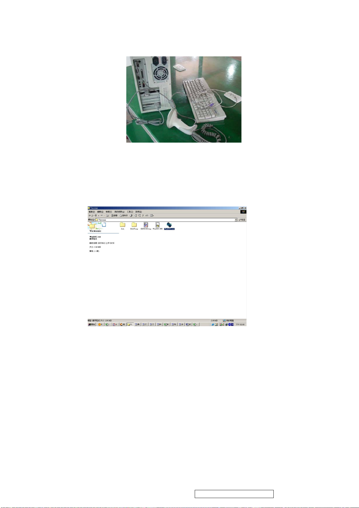
2. Barcode Reader connects with keyboard and PC keyboard port.
ViewSonic Corporation
46
VT2430-1M
3. Connect DDC Card and VT2430-1M LCD TV with VGA Cable.
(when key in DVI DDC information, use VGA transform to DVI port )
4. Connect Power Cord to VT2430-1M LCD TV.
5. Press ‘MENU’and ‘ENTER’ at the same time, then go into the BURN IN MODE.
5.5.3 DDC Key In Procedure
1. run DDC exe
Confidential - Do Not Copy
Page 50
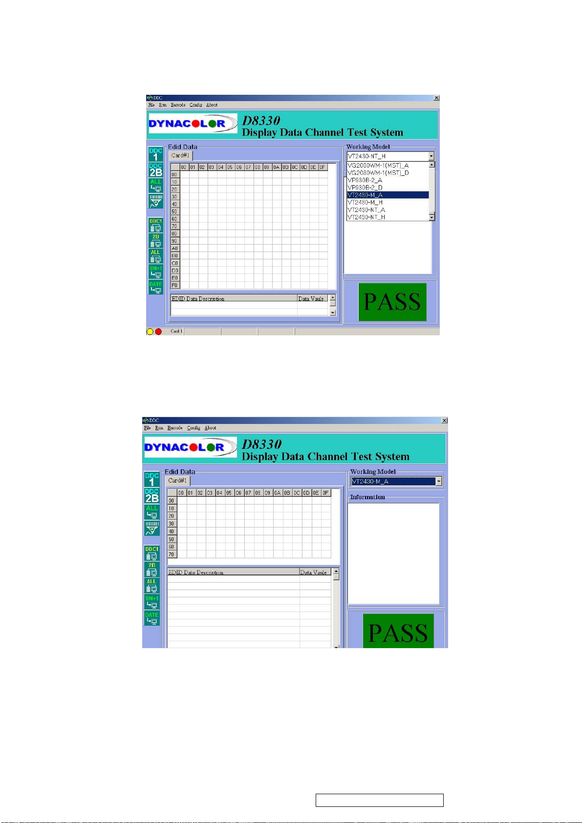
2. Choose model number the
ViewSonic Corporation
47
VT2430-1M
3. Press “ENTER” key.
Confidential - Do Not Copy
Page 51
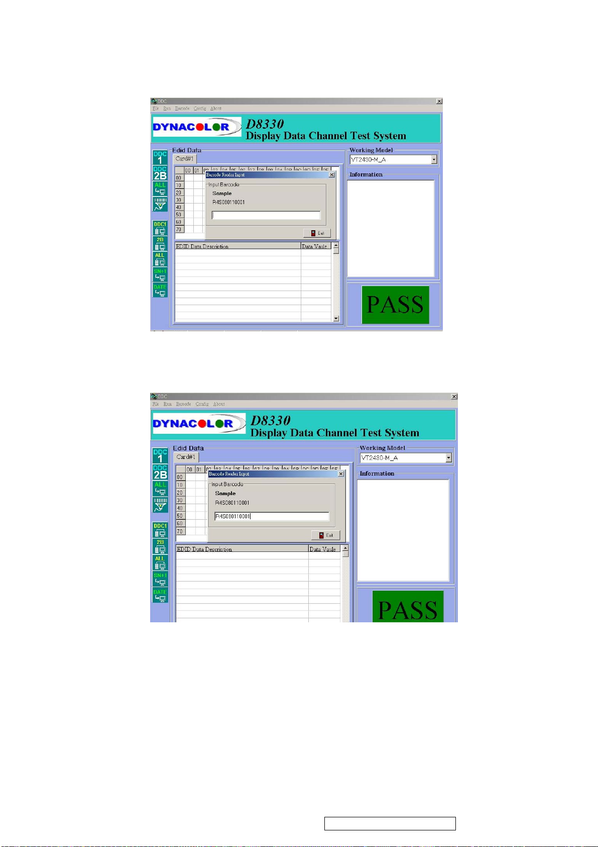
4. Press “F4” key and Input bar code
ViewSonic Corporation
48
VT2430-1M
Confidential - Do Not Copy
Page 52
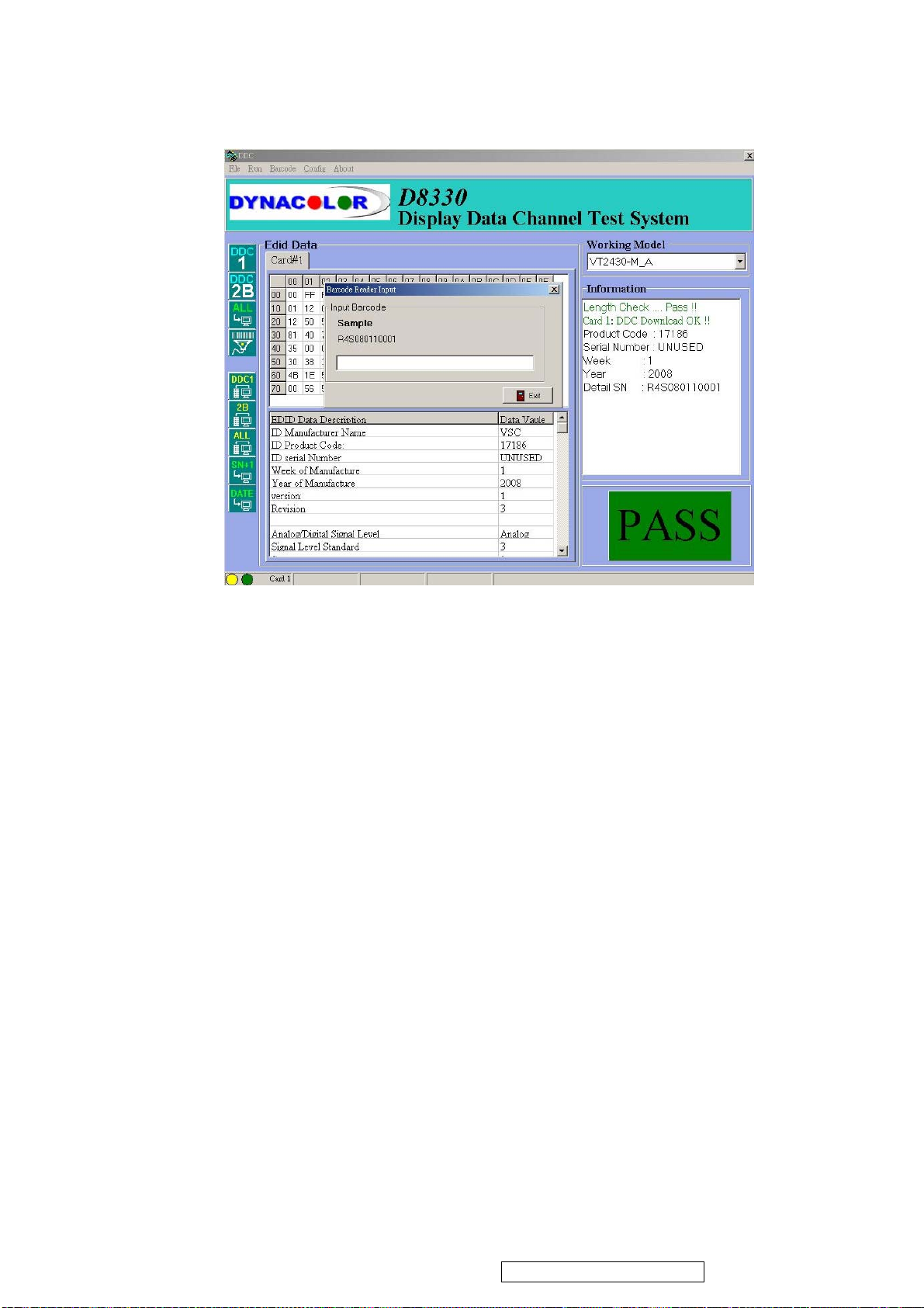
5. Press “ENTER” key, then the successful picture is as follows. “DDC DOWNLOED OK!
ViewSonic Corporation
49
VT2430-1M
6. Exit program.
Confidential - Do Not Copy
Page 53
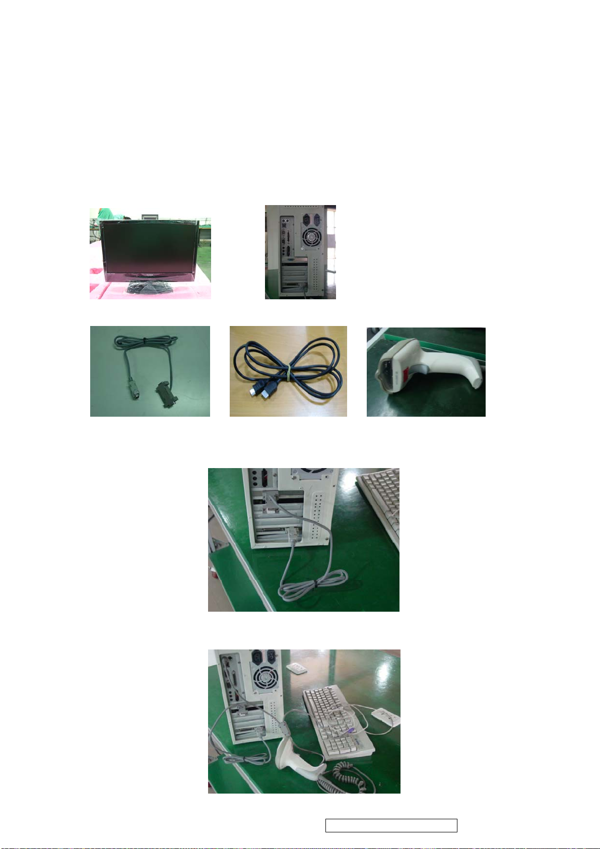
5.6 HDMI DDC Key In Procedure
ViewSonic Corporation
50
VT2430-1M
There are three EDID files for the different HDMI connectors. So you must be download the
different EDID into each HDMI connector.
5.6.1 Equipment Needed
- VT2430-1M LCD TV
- PC
- RS-232 cable
- Barcode Reader
- HDMI Cable
-
VT2430-1M LCD TV PC
RS-232 Cable HDMI Cable Barcode Reader
5.6.2 Setup Procedure
1. Connect HDMI Card and DDC Card with RS-232 cable.
2. Barcode Reader connects with keyboard and PC keyboard port.
Confidential - Do Not Copy
Page 54
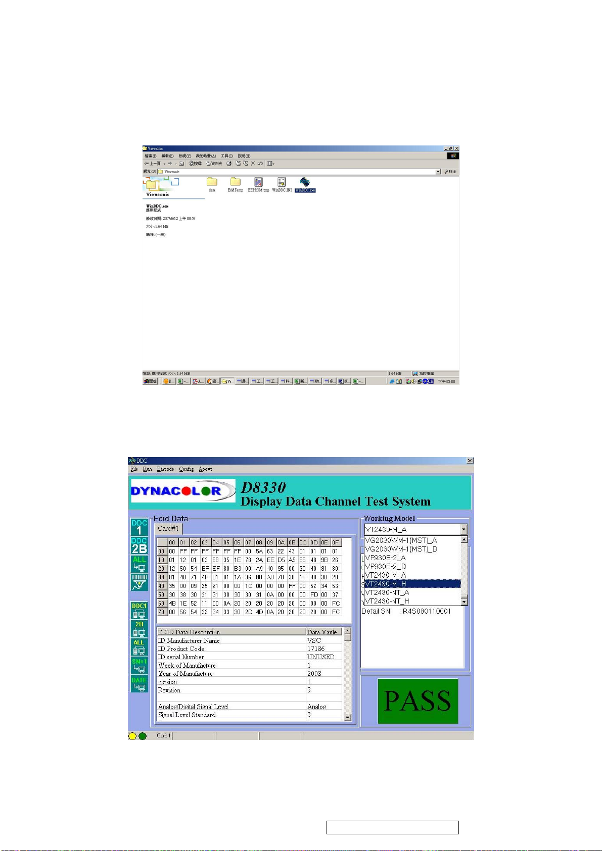
3. Connect DDC Card and VT2430-1M LCD TV with HDMI Cable.
ViewSonic Corporation
51
VT2430-1M
4. Connect Power Cord to VT2430-1M LCD TV.
5.6.3 DDC Key In Procedure
1. Run DDC.exe
2. Choose model number then
Confidential - Do Not Copy
Page 55
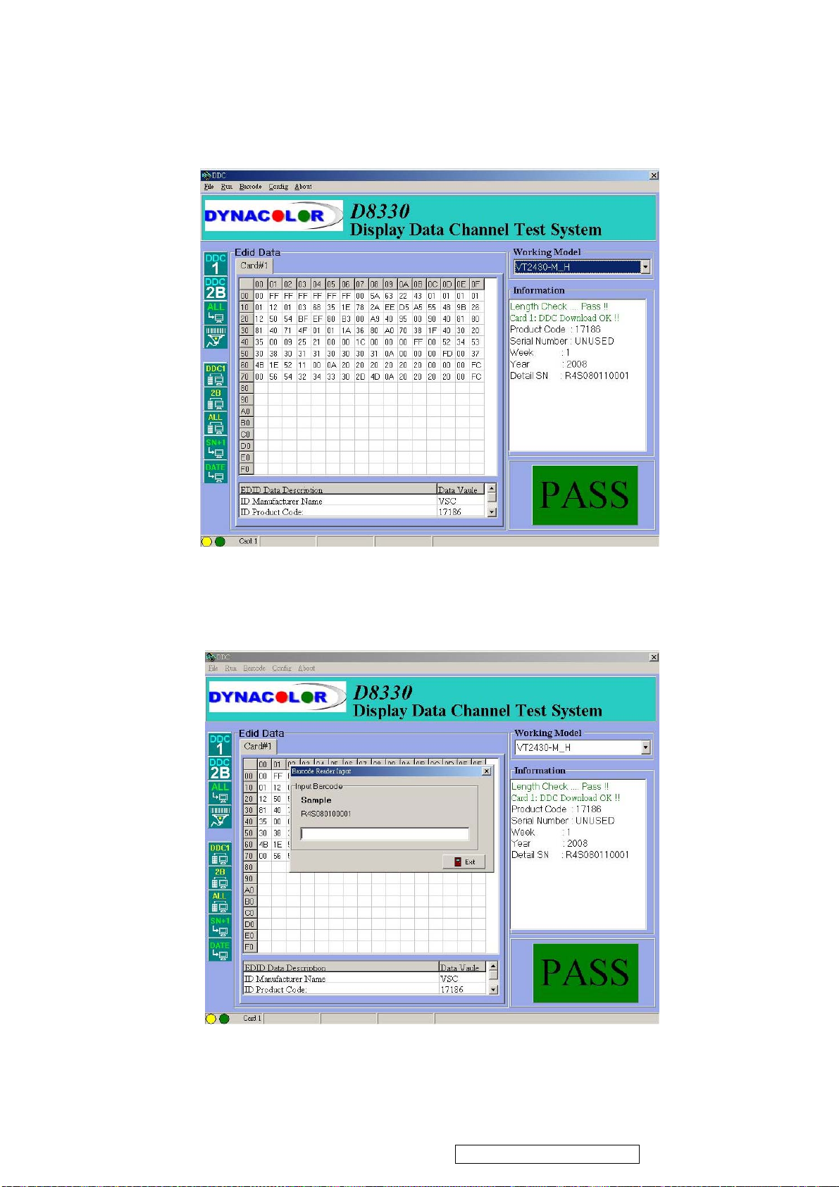
ViewSonic Corporation
52
VT2430-1M
3. Press “ENTER” key.
4. Press “F4” key.
Confidential - Do Not Copy
Page 56
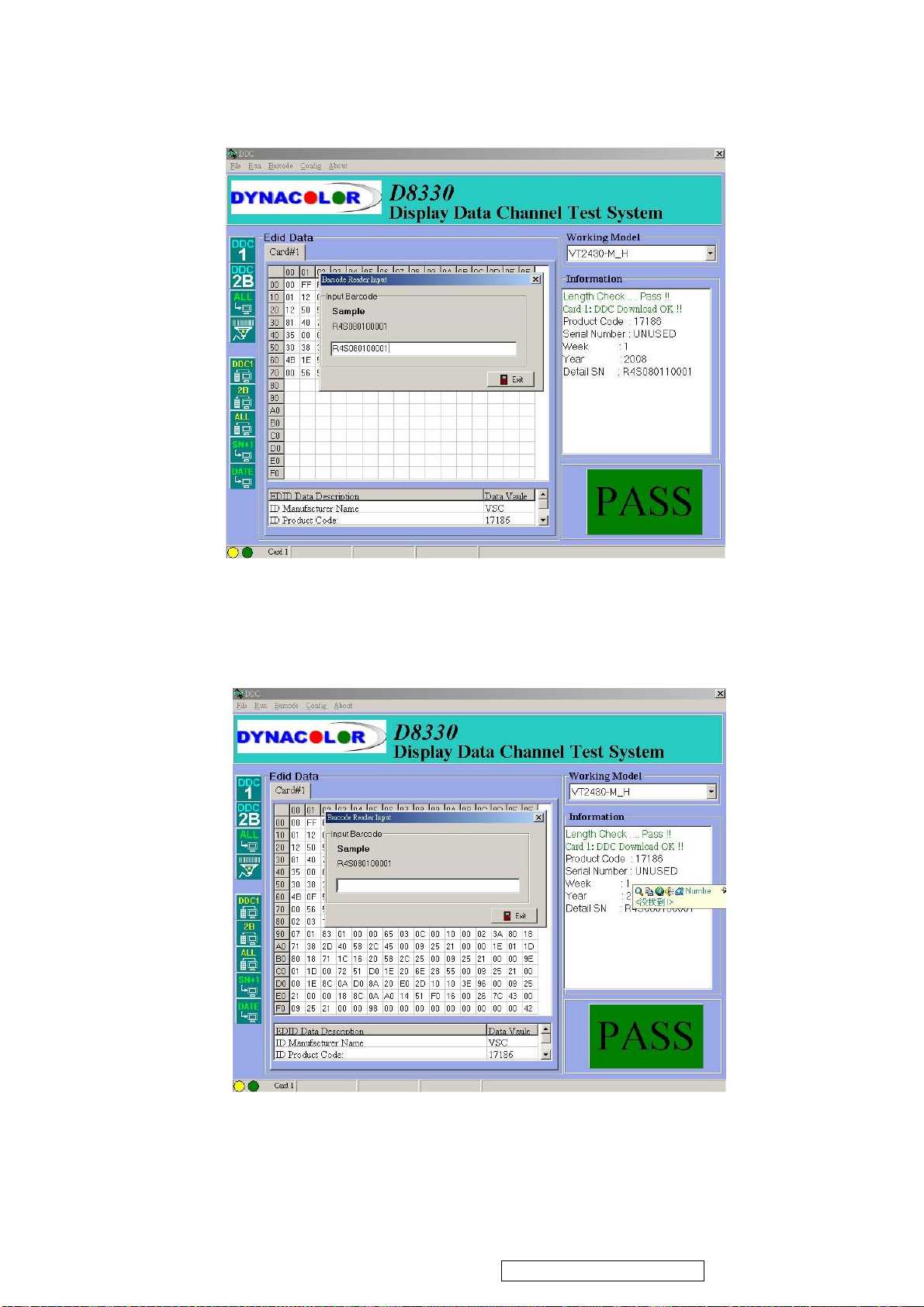
5. Input bar code
ViewSonic Corporation
53
VT2430-1M
6. Press “ENTER” key, then the successful picture is as follows. “DDC DOWNLOED
OK!
7. Exit program
Confidential - Do Not Copy
Page 57
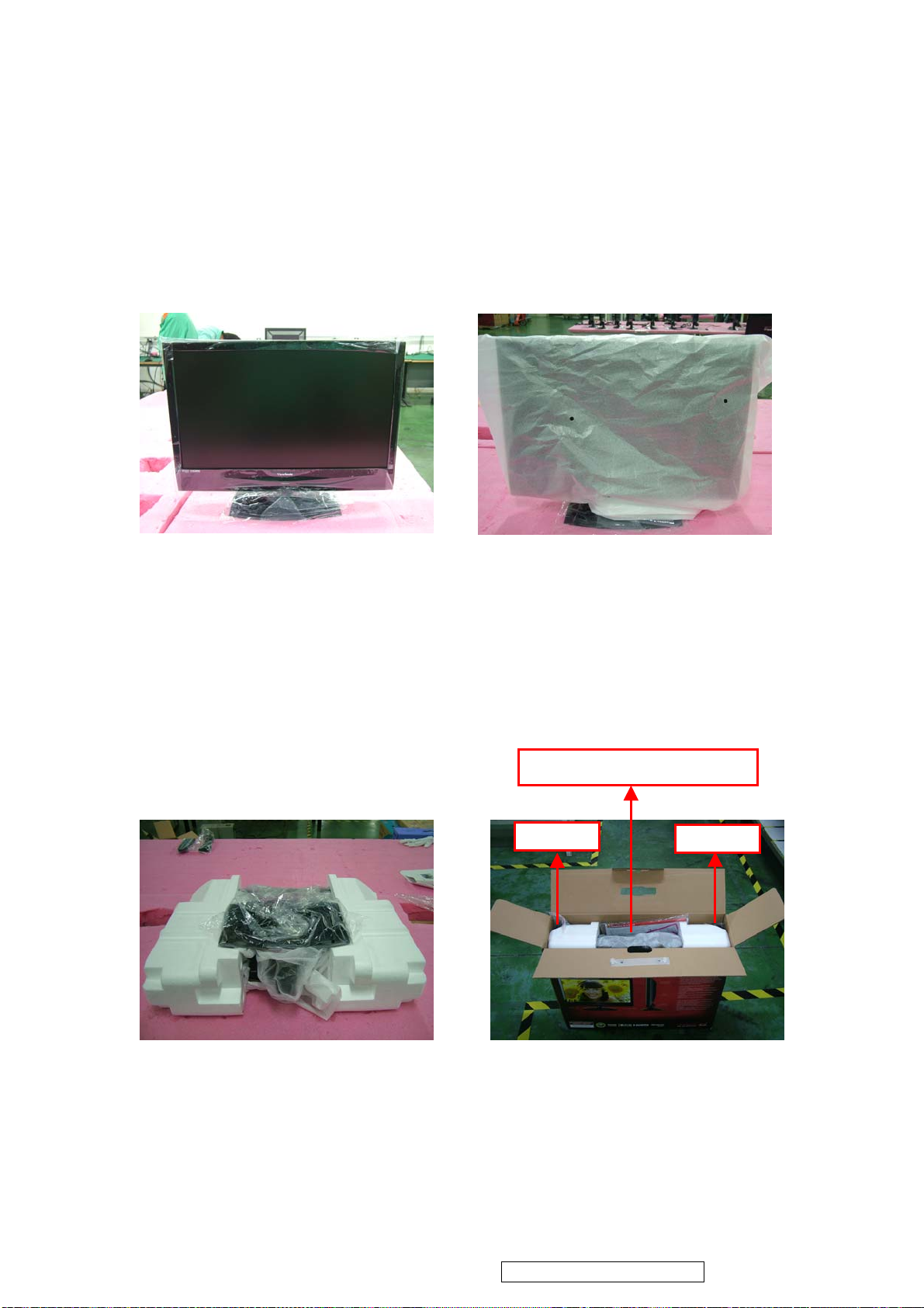
Packing For Shipping And Disassembly Procedure
ViewSonic Corporation
54
VT2430-1M
Packing For Shipping
1. Packing Procedure
1.1 Paste protection film to protect the LCD TV. (Figure 1)
1.2 Put the LCD TV in the PE bag and seal the bag. (Figure 2)
1.3 Put the cushions on the LCD TV. (Figure 3)
1.4 Place the LCD TV into the carton and put all the accessories into the carton. At last, close the
carton and seal it with tape. (Figure 4)
Figure 1 Figure 2
1.User’s Guide 2..Guarant Card 3.Battery
Power Cord
Remote contrl
Figure 3
Figure 4
Confidential - Do Not Copy
Page 58
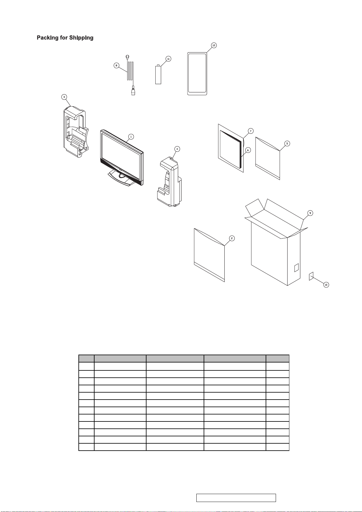
Item
ViewSonic P/N
Ref. P/N
Description
Q'ty
ViewSonic Model Number: VS12335-1M
PACKING PART LIST (VT2430-1M)
ViewSonic Corporation
55
VT2430-1M
Rev:
1 VT24301M monitor 1
2
3
4
5
6
7
8
9
10
11
12
P-00008938 2013053000P POLYETHY BAG 1
P-00009323 2012114500P POLYFOAM(R) 1
NA 2012154600P POLYFOAM(L) 1
P-00008947 2013222536P POLYETHY BAG 1
NA 2001132017P CD-OWNER GUIDE 1
NA 2002310787P GUARANT CARD 1
A-00005362 2427130046P AC POWER CORD 1
P-00009322 2011124001P CARTON BOX 1
NA 2055632329P LABEL 1
NA 2005100401P BATTERY,DRY 2
A-00008204 2419200161P CONT BLOCK 1
Confidential - Do Not Copy
Page 59
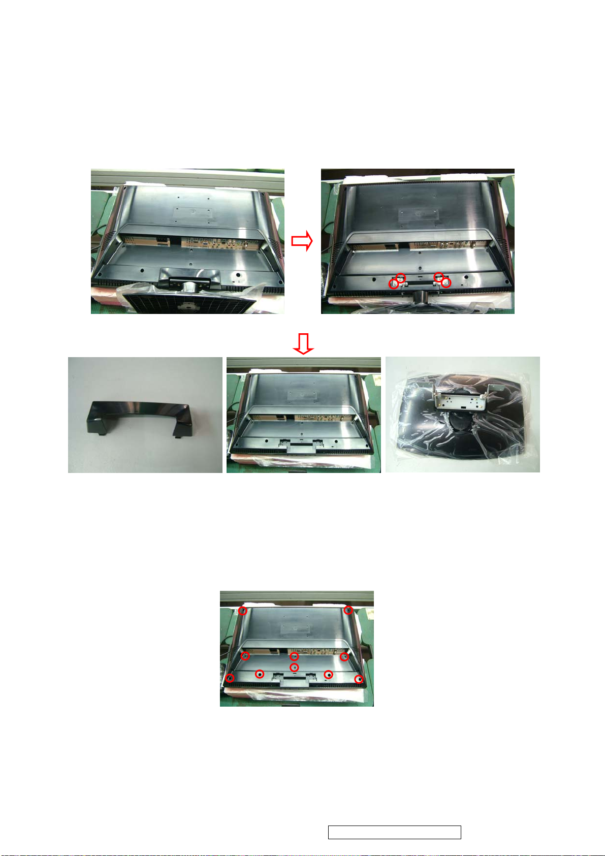
Disassembly Procedure
ViewSonic Corporation
56
VT2430-1M
1.
Disassembly of Stand from LCD TV.
1.1 Unscrew 4 screws to move Stand Unit and Dust Cover .
Dust Cover
2. Disassembly of Rear Cover.
2.1 Unscrew 10 screws in the Rear Cover.
Stand
Confidential - Do Not Copy
Page 60
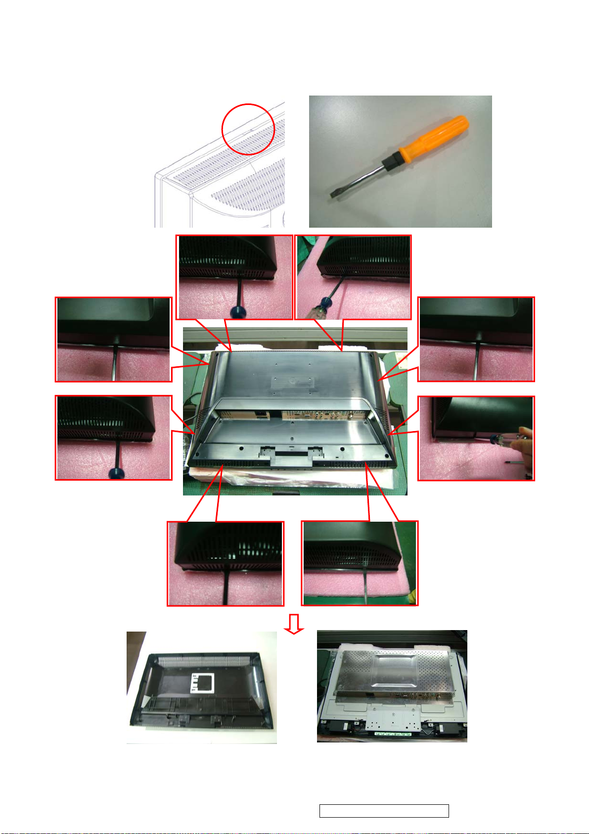
2.2 Prize the rectangle hole on Rear Cover (Fig.1) with a screwdriver(Fig.2) to make the Rear Cover
ViewSonic Corporation
57
VT2430-1M
detach from the LCD TV.
Fig.1 Fig.2
Rear Cover
Confidential - Do Not Copy
Page 61
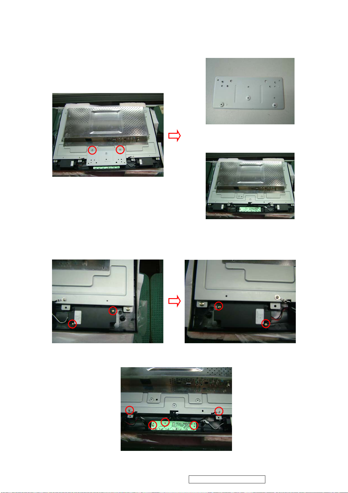
3.
ViewSonic Corporation
58
VT2430-1M
Disassembly of Main Board, Power Board, Front Cover and Panel Unit.
3.1. Unscrew 2 screws to remove Bracket fix.
Bracket fix
3.2. Unscrew 9 screws to move Speaker and KeyPad Board .
Confidential - Do Not Copy
Page 62
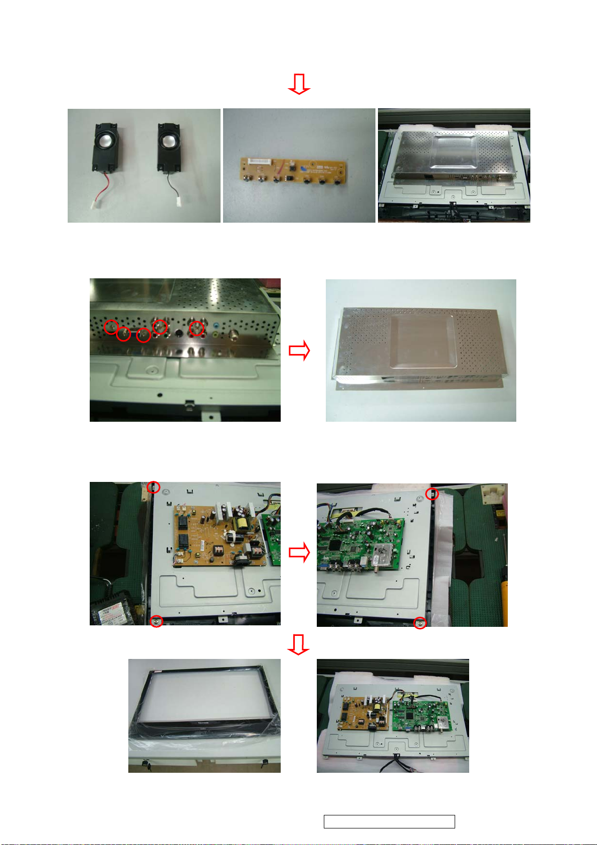
ViewSonic Corporation
59
VT2430-1M
3.3. Unscrew screws 5 to move Shield Plate .
3.4. Unscrew 4 screws and disconnect the wires to remove Main Board.
Speaker
KeyPad Board
Shield Plate
Front Cover
Confidential - Do Not Copy
Page 63
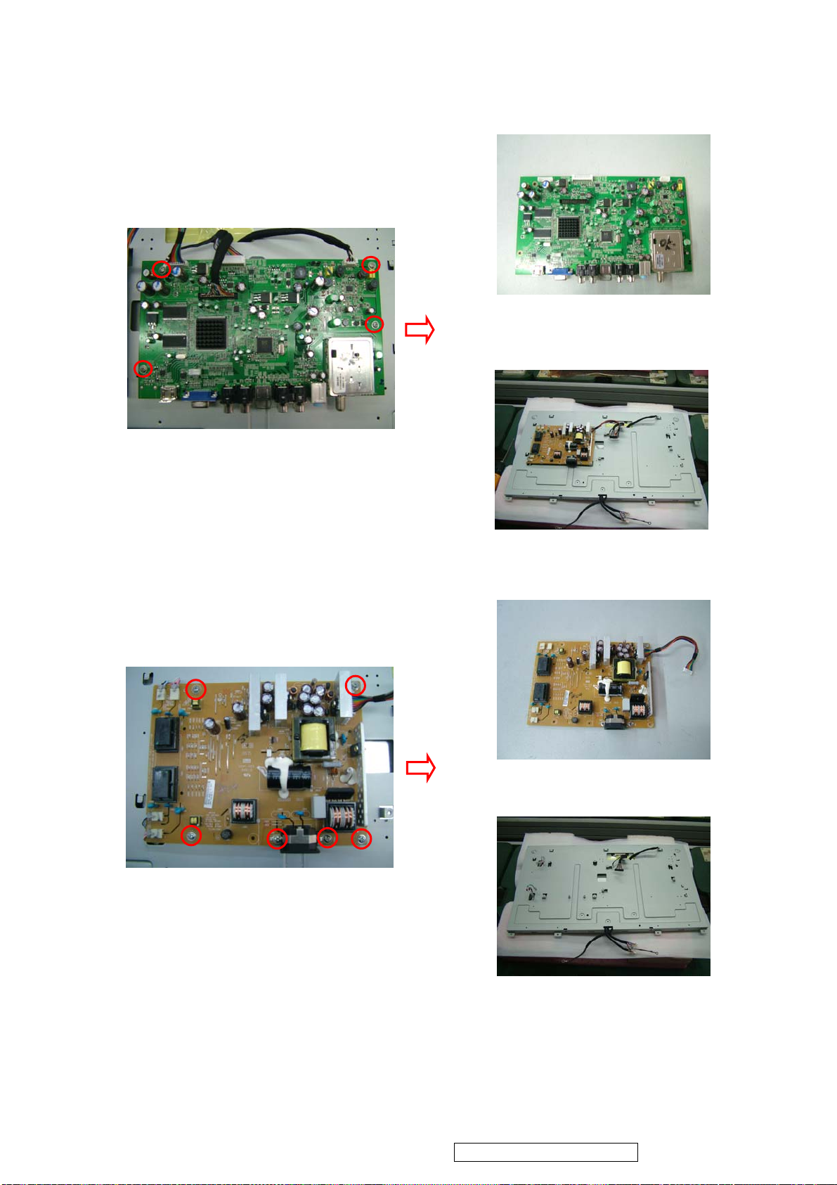
3.5. Unscrew 4 screws and disconnect the wires to remove Main Board.
ViewSonic Corporation
60
VT2430-1M
Main Board
3.6. Unscrew 4 screws and disconnect the wires to remove Power Board.
Power Board
Confidential - Do Not Copy
Page 64
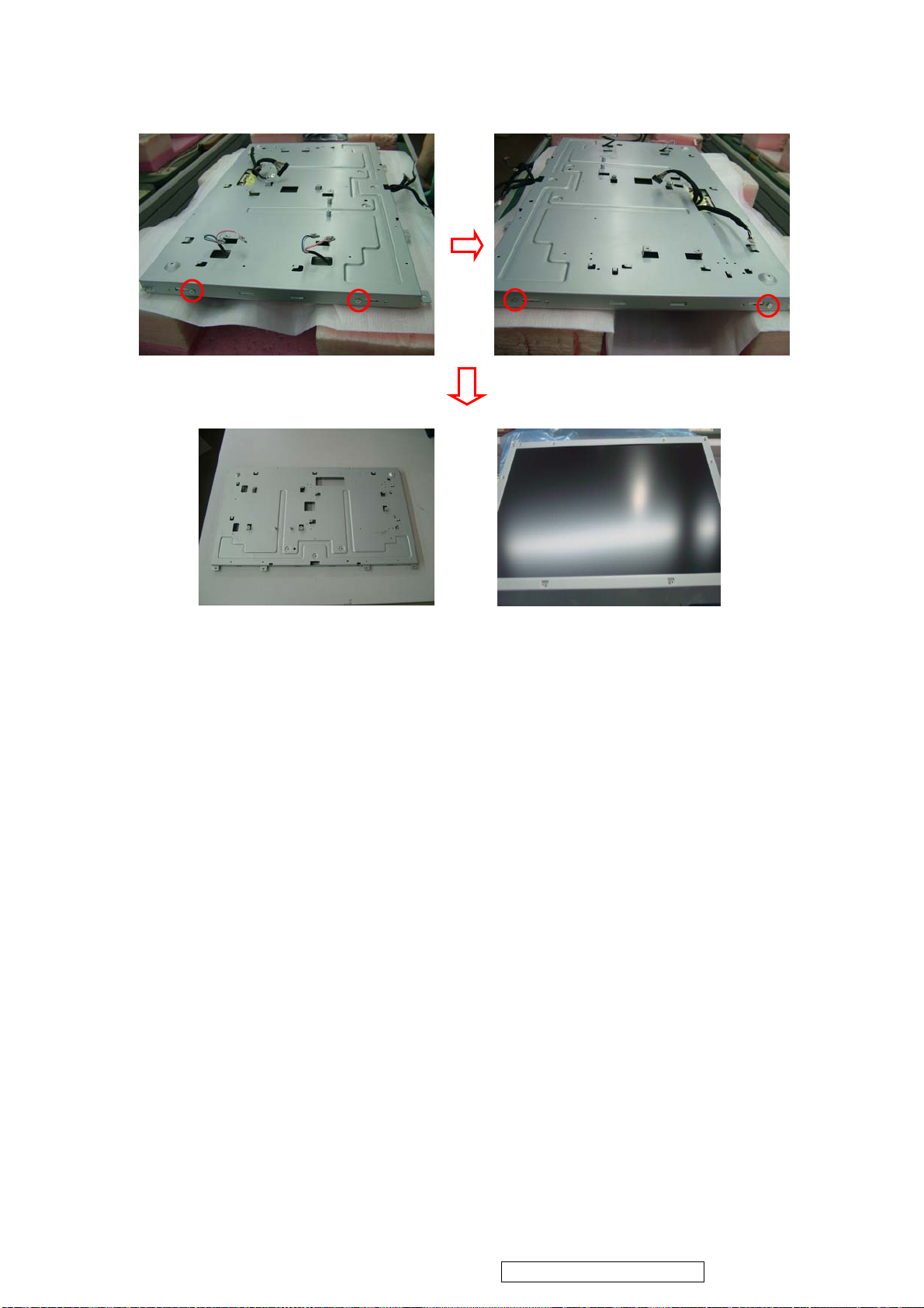
3.7. Unscrew screws 4 to move Panel Bracket .
ViewSonic Corporation
61
VT2430-1M
Panel Bracket
Confidential - Do Not Copy
Page 65
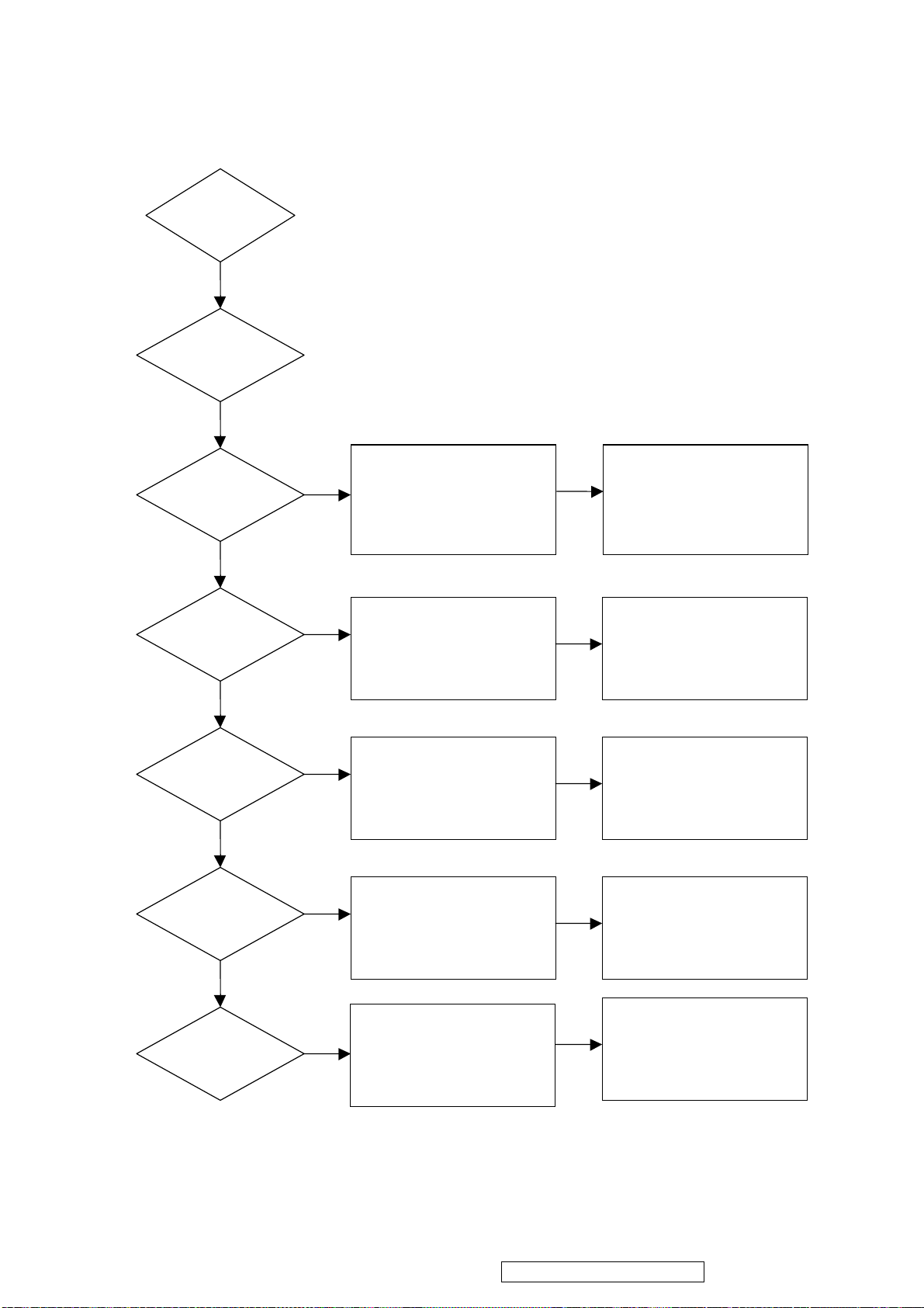
6. Trouble Shooting Flow Chart
ViewSonic Corporation
62
VT2430-1M
START
CHECK MAIN PCB
-
-
CHECK
POWERPCB
OK
CHECK
D807,I801,I801
I103,SUROUND CAP
BEAD OK?
CHECK
D807,I801,I801
I204,SUROUND CAP
BEAD OK?
CHECK
D807,I801,I801
I105,SUROUND CAP
BEAD OK?
CHECK
Q105,Q106
D807,I801,I801
OK?
Y
Y
CHECK
P101
OK?
CHECK
I206
Y
I202
Y
SUROUND CAP OK?
Y
CHECK
I206
CHECK
I107
SUROUND OK?
Confidential - Do Not Copy
Page 66
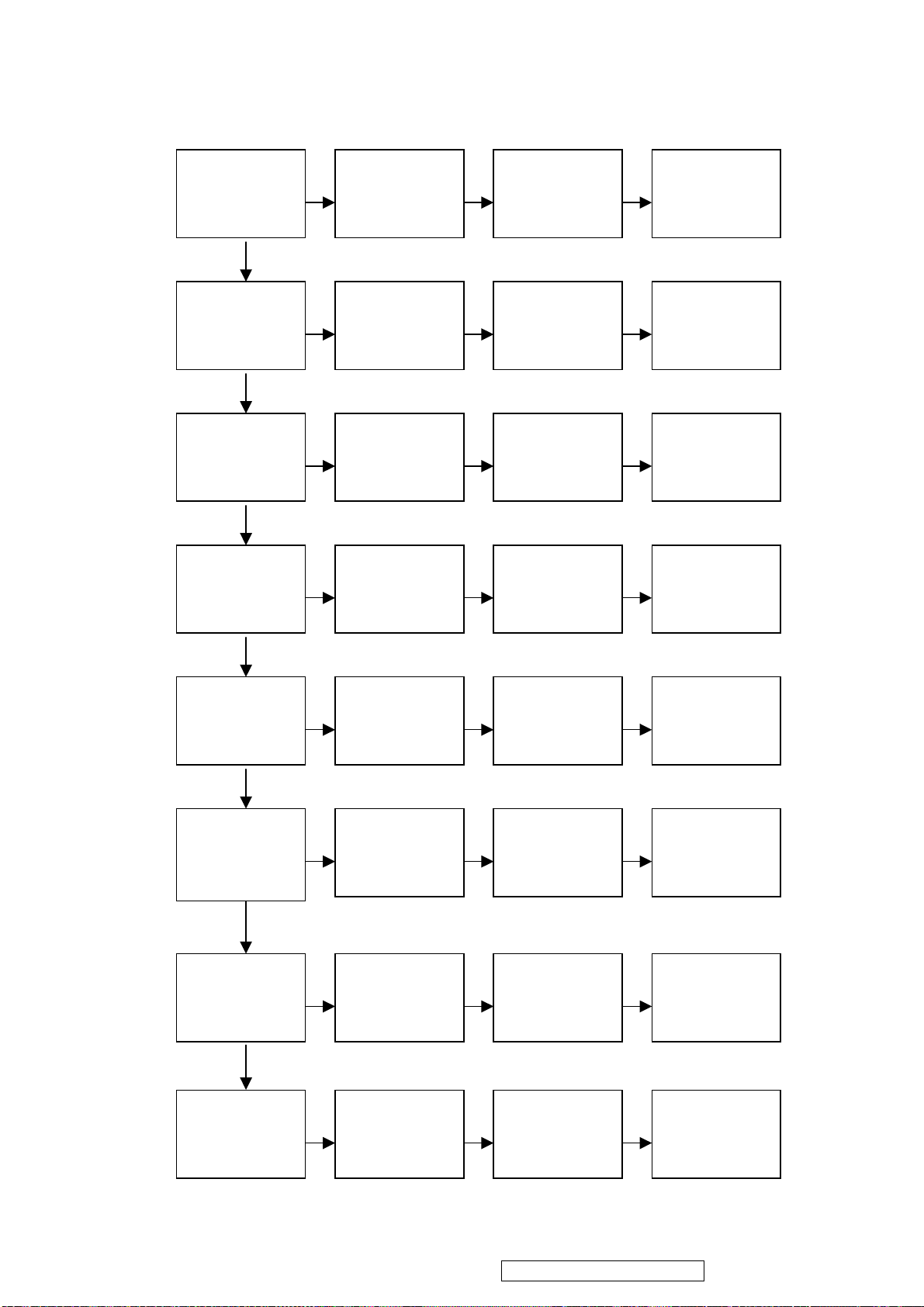
6.1 NO DISPLAY
N
N
N
N
N
N
N
N
N
N
N
N
N
N
N
N
N
N
N
N
N
N
N
N
ViewSonic Corporation
63
VT2430-1M
Power key
Work ok Keypad P701
Y
Check
PANEL 5V
Y
Check
PC SOUCE
Y
Check
AV SOUCE AV cable
Y
Check
S-Video SOUCE S-Video cable
Y
Check
YPbPr SOUCE
Y
Check
TV SOUCE
Y
Check
HDMI SOUCE
Check
Check
Q105,Q106
Check
D-sub cable
Check
Check
Check
YPbPr cable
Check
RF CABLE
Check
HDMI
Check
I710
Check
Check
I503
Check
P504
Check
P503,SUROU
Check
P504,SUROU
I107,SUROUND
Check
Check
Check
X202
Check
PANEL P106
Check
I503,SUROUND
Check
L503, R576, C538
Check
Check
Check
L502 I501TUNER
Check
I502 P501SUROUN
R561,R565,L505,
L506,C521,C527
R567, R570, R573
Confidential - Do Not Copy
Page 67
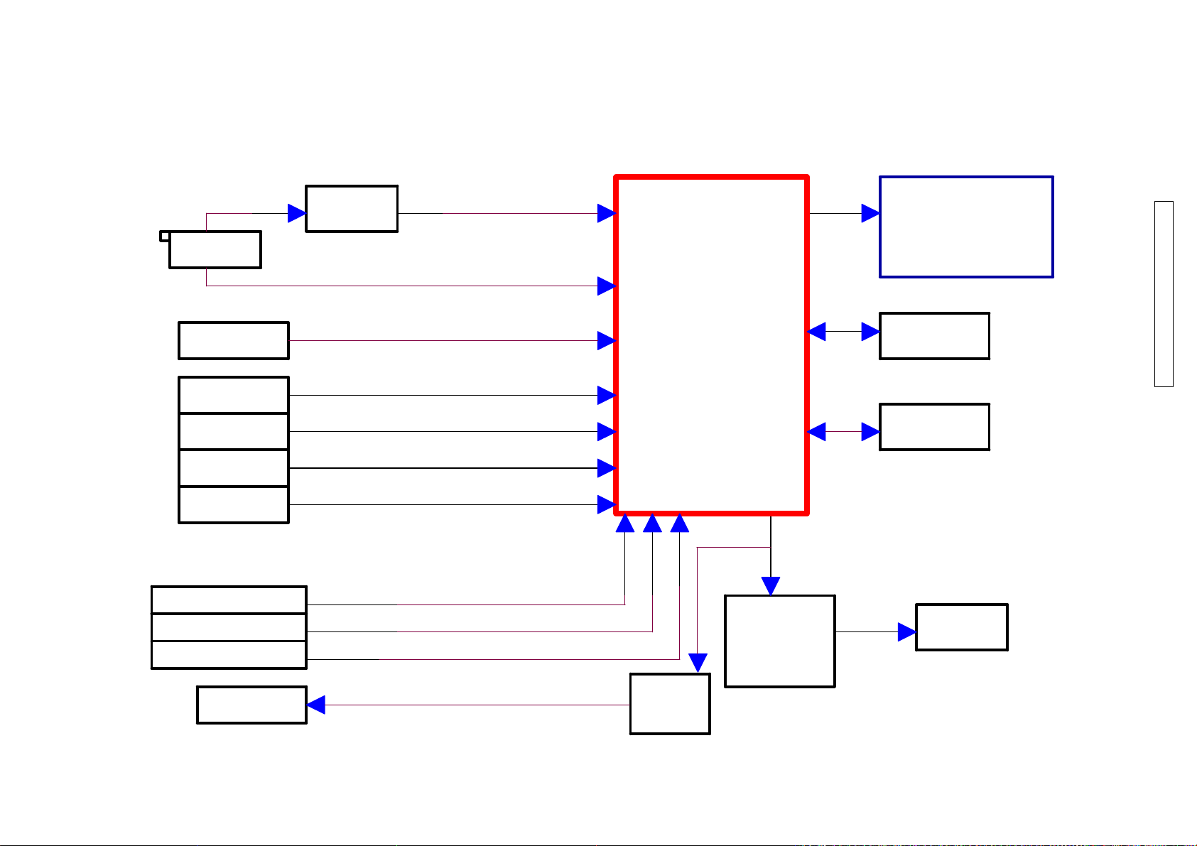
7. Block Diagram
ViewSonic Corporation
VT2430-1M
MSD809(DEMO)
COMBO TUNER
ATSC
HDMI
AV(CVBS)
S_VIDEO DDRx2
YPbPr
PC(D-Sub)
AV/SV Audio(RCAx2)
YPbPr Audio(RCAx2)
PC Audio(mini jack)
MSD2248AL
YAMAYA 148
LCD Module
Flash
Confidential - Do Not Copy
64
Speaker
(6Wx2)
EAR PHONE
OUT
TPA6113A2
Page 68
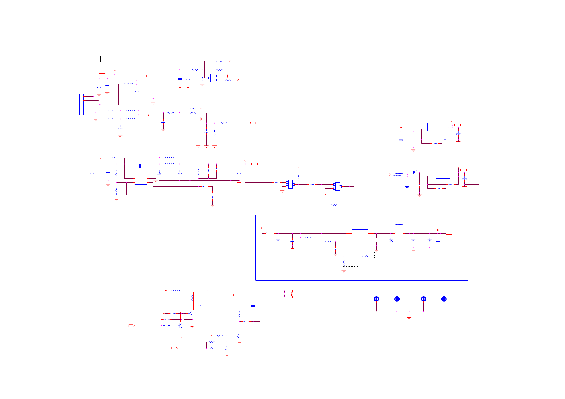
8. Schematic Diagrams
ViewSonic Corporation
65
VT2430-1M
8.1. System Power
91
12V
12V13
C109
+
C108
100nF/0603
1500u/16V LESR
P101
1
2
ADJPWMA
3
4
5
BKLON
6
7
8
9
L123 NC/600uH DIP
L101
DUAL BEAD 100R
1500u/16V LESR
C101
L102 40uH DIP
C110
1500u/16V LESR
L103 80R 0805 6A
L104 80R 0805 6A
+
+
0 ~ 3V3
VCC5V-ST
VCC5V-ST 6,8,10,13,15
C111
NC
5VAMP 12,13
BKLON
5VAMP
C112
NC
ADJPWMA
R139 1K
C103
NC
3
Q101
C
NC/3904
R102 0R
+
C102
NC
R107 NC
R108 0R
E
2
23
SOT
B
1
R104
NC
VCC5V-ST
C115
100nF
3
NC/3904
+
C114
NC
Q102
C
R103 NC
R106 100R
E
2
23
SOT
B
1
R109
4.7K
R105
NC
high turn on
R101 0R
VCC5V-ST
VBLCTRL-GPIO12
BRI_ADJ-PWM2 6
VBLCTRL-GPIO12 6
3.3V Stand-by Power
I103 1084-3.3
VCC5V-ST
10u/16V
+
C119
C118
100nF
1
ADJ
VCC3.3V_ADJ
R111
0R
VCC3.3V-ST
23
VOUTVIN
4
TAB
R110
NC
VCC3.3V-ST 6
+
C116
220u/16V LESR
C117
100nF
12V
C160
+
470u/35V/LESR
L120 600R/1.5A 0805
R180
C161
NC
100nF
R181
NC
measure current
C162 100nF
6
5
I109 MP2359DJ/TSOT23-6
1
BST
SW
2
GND
IN
34
FBEN
L121 NC
L122 22uF/15uF
D136
SR36
ONLY C617 C142 C141ARE 50V OTHER IS 16V
CHIP CAP
modify about panel VCC rise time and power off pulse noise 081014
VCC5V-ST
VCC5V-ST
R141
NC
R133
PANEL-ON/OFF-GPIO116
PANEL-ON/OFF-GPIO11
POWER-ON/OFF-GPIO446.13
4.7K
C165
+
47u/16V
L114 80R 0805 6A
R131
4.7K
1
C169
NC/10uF/0805
32
Q106
1
MMBT3904
POWER-ON/OFF-GPIO44
100K 1% 0603
C163
100nF
R184 4K75 1% 0603
R129
10K
R130
4.7K/100R
32
Q105
MMBT3904
R182
100K 1% 0603
VCC5V-ST
C171
100nF
R142
NC
R136
10K
R183
C166
NC
R185
4K75 1% 0603
R135
10K
1
VCC5V-ST
32
Q108
MMBT3904
5VIF
+
C167
C164
220u/16V LESR
100nF
POWER-ON/OFF-GPIO44
measure current
R132
10K
R134
4.7K/100R
32
Q107
1
MMBT3904
5VIF 4
R186 10K
1.2V Core Power
VCC5V-ST
L110
600R/1.5A 0805
I107
STM4953
1
S2
D2
2
G2
D2
3
S1
D1
4
G1
D1
C170
100nF
Q120
1
B
SOT
23
2
E
MMBT3904
VCC5V_IN
C131
+
47u/16V
8
7
PANEL-VCC
6
+5V_General
5
measure current
VCC5V-ST
R187
10K
R188 4.7K
3
C
R123
3K 0603/2.2K
C133
C136
100nF
100nF
PANEL-VCC 14
+5V_General 3,4,8,10,15
1
2
R189 4.7K
VCC5V_OCSET
R124
100K 0603
1.62K 1% 0603
Q121
B
SOT
C
23
E
NC/MMBT3904
VCC5V_EN
C139
100nF
R128
3
I105
AP1533/AP1534
4 5
VCC OUTPUT
3
OCSET
2
EN
1
FB
VCC1.2V_FB
RB
600R/1.5A 0805
L108
VCC5V-ST
L109 NC
+5V_General
L124 NC
measure current
VCC1.2V_OUT
6
OUTPUT
VSS
VSS
R126
1K 1% 0603
7
8
RA
D102
SR36
Vout=VFB*(1+RA/RB)
VFB=0.8V
RB=0.7K~5Kohm
1
1
2.5V Power
D133 GS1B
+
C129
10u/16V
L111
22uH/2.9A
+
1
1
1
C130
VCC2.5V_ADJ
100nF
Vout=Vref*(1+R2/R1)+Iadj*R2
Vref=1.25V
VCC1.2V-ST
+
C132
220u/16V LESR
C134
1u/50V
1
1
I104 1084-ADJ
VOUTVIN
ADJ
TAB
R120
110R 1% 0603
R2
C135
100nF
1
1
VCC2.5V-ST
23
4
R117
100R 1% 0603
R1
VCC1.2V-ST 6
VCC2.5V-ST 6,7
+
C127
220u/16V LESR
C128
100nF
Confidential - Do Not Copy
Page 69
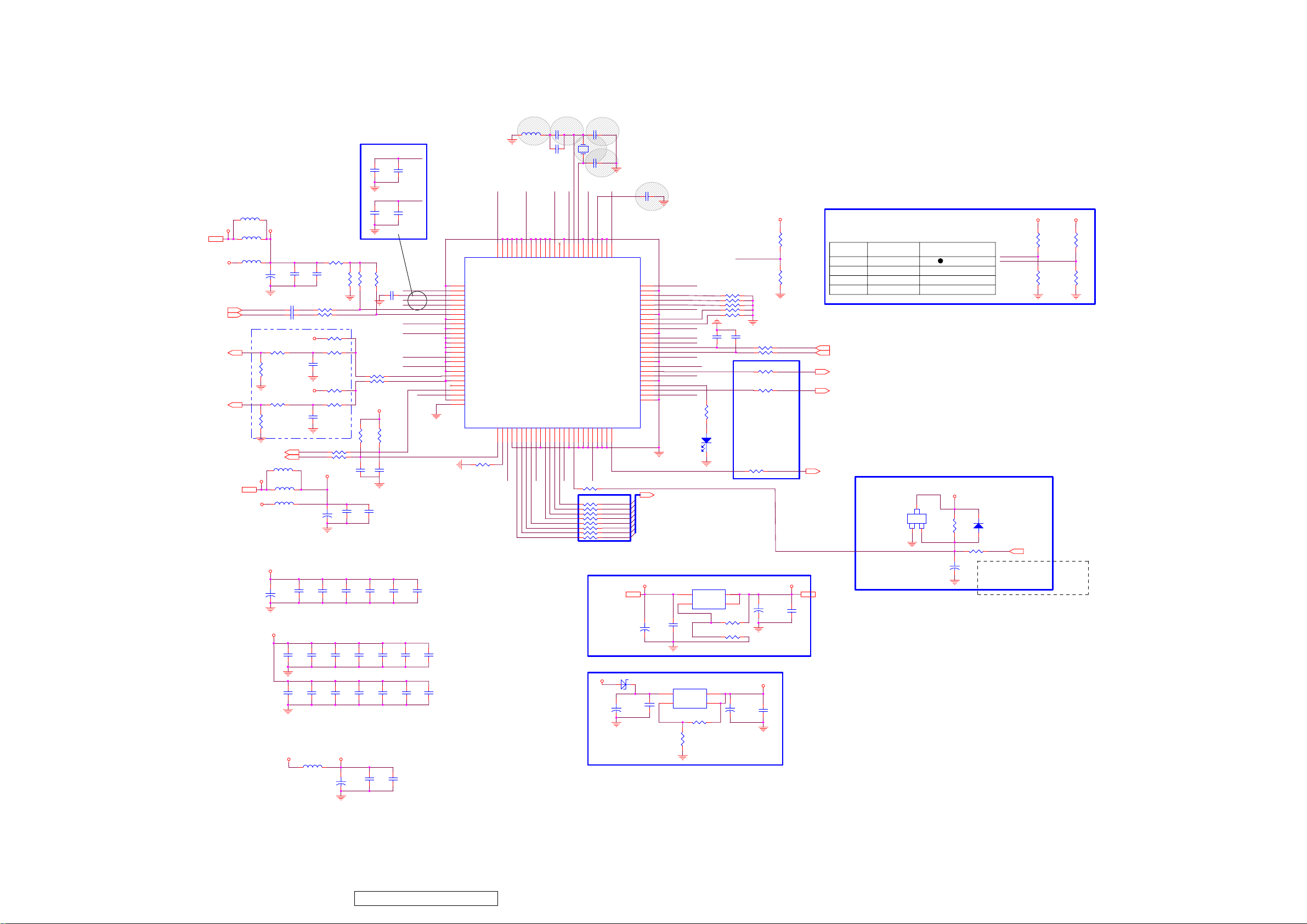
ViewSonic Corporation
66
VT2430-1M
8.2. DTV-MSD809
Tuner-5V4
+5V_General
IFAGC4
RFAGC14
Tuner-5V
IF-4
IF+4
Tuner-5V4
L214 NC
L203 10uH
L201
NC/600R/1.5A 0805
IFIF+
Close to demod
Tuner-5V
DTV-VDD33
DTV-Pull_Up
+
C233
10u/16V
10nF/0603
C242
C243
10nF/0603
DTV-Pull_Up_1
R225
0R
R228
NC
DTV-Pull_Up_1
R235
NC
R238
NC
T_SCL4
T_SDA4
L213 NC
L212 NC/10uH
L210 600R/1.5A 0805
DTV-VDD33
+
C218
10u/16V
DTV-VDD12
C228
100nF
C235
100nF
C338
NC/470pF
C219
100nF
R217
1K
C234
100nF
499R 1% 0603
R221 220R
R222 220R
R223
220R 0603
R226
1K
C244
100nF
R233
NC
R236
NC
C248
NC
R241 100R
R242 100R
DTV-Pull_Up_1
+
C322
10u/16V
C220
100nF
C229
100nF
C236
100nF
R218
C230
100nF
C237
100nF
R219
1K
R231 0R
R232 NC/0R
R239
4.7K
C334
22pF
C339
1nF
C221
100nF
C231
100nF
C238
100nF
C216
100nF
C226
100nF
R220
1K 0603
DTV-Pull_Up_1
R240
4.7K
TUNER_SCL
TUNER_SDA
C335
22pF
C323
100nF
C222
100nF
C232
100nF
C239
100nF
REF_BOT
10uF/0805
C217
REF_TOP
10uF/0805
C227
DTV-AVDD33_ADC
C241
100nF
REF_BOT
REF_TOP
DTV-IFN
DTV-AVDD33_ADC
DTV-VDD12
DTV-VDD12
DTV-VDD12
DTV-IF_AGC
DTV-RF_AGC
C223
100nF
C340
100nF
C240
100nF
DTV-IFP
DTV-VDD33
C224
100nF
C341
100nF
C342
100nF
76
77
78
79
80
81
82
83
84
85
86
87
88
89
90
91
92
93
94
95
96
97
98
99
100
101
I202
VSSBBH_ABB
VDD33TH_ABB
CML
RN
RP
AIN
AIP
VSSBBTH_ABB
VDD33TH_ABB
VSSIPH
VDD12IH
D_IN3
D_IN2
D_IN1
D_IN0
VDD12IH
VSSIPH
VDD12IH
VSSIPH
IF_GAIN
TU_GAIN
GPIO_OUT1
TUNER_CLK
VDD33OPH
VSSOH
GND
R361
L202
NC/1uH 0603
DTV-VDD33
75567453735272617158705569516859676066576554646263
D_IN4
D_IN5
D_IN6
D_IN7
VSSIPH
VDD33OPH
TUNER_SDA
GPIO_IN1
VDD12IH
VSSIPH
PKDATA7
PKDATA6
12345678910111213141516171819202122232425
NC/0R
DTV_TS-D6
DTV_TS-D7
DTV-VDD12
DTV_TS-D5
DTV-VDD12
VDD12IH
MSD809
PKDATA5
DTV_TS-D4
VSSIPH
PKDATA4
DTV-VDD12
D_IN8
VDD12IH
D_IN9
D_IN10
VSSIPH
PKDATA3
DTV_TS-D3
C213
NC/560pF 0603
C324NC/56pF 0603
DTV-VDD12
D_IN11
VDD12IH
PKDATA2
PKDATA1
DTV_TS-D2
DTV_TS-D1
DTV_TS-D0
CLK_EXT_ADC
PKDATA0
DTV-VDD33
DTV-VDD33
VSSIPH
VDD33OPH
VDD33OPH
VSSOH
LEO-XOUT
OSC_XOUT
RESET_N
DTV-RESETN
X201
49.38111MHz
LEO-XIN
DTV-VDD12
VSSOH
OSC_XIN
VDD12T_ABB
TEST_BIRA
TEST_SIG0
TEST_SIG1
R274 0R
R651 100R
R652 100R
R653 100R
R654 100R
R655 100R
R656 100R
R657 100R
R658 100R
Close to Demodulator
3.3V DTV Demodulator
1.2V DTV Demodulator
C214
27pF/0603
C215
27pF/0603
FILTER
VBB_ABB
VSSBB_ABB
VDD12IH
VSSIPH
TEST_SIG2
DTV-VDD12
DTV_RESET
+5V_General2,4,8,10,15
DTV-VDD33
MSB1501/ S5H1409 option
* C227 on for S5H1409.
* S5H1409 pin 51, 56, 91 must connect to 1.2V
* R322, R325, R324on: S5H1409.
* R328=220, R358=1K, C166= 100nF for S5H1409; R328=1K, R358=10K, C166= 20nF for MSB1501
C225
DTV-VDD12
VSST_ABB
VDD12T_ABB
TEST_SEL0
TEST_SEL1
TEST_SEL2
TEST_SEL3
TEST_SEL4
VDD33OPH
EXT_PLL_SEL
VDD33OPH
TEST_SIG3
PKCLK
TS_D0
TS_D1
TS_D2
TS_D3
TS_D4
TS_D5
TS_D6
TS_D7
10u/16V
1500pF/0603
PLL_SEL
DTV-VDD12
50
VDD12IH
49
VSSIPH
48
47
46
DTV-VDD12
45
VDD12IH
44
VSSIPH
43
42
DTV-VDD33
41
40
VSSOH
I2CADDR1
I2CADDR0
SCL
SDA
VDD12IH
VSSIPH
PKVAL
VDD12IH
VSSIPH
PKERR
PKSYNC
VSSOH
+5V_General DTV-VDD33
D207
C256
+
C255
100nF
39
38
37
36
35
34
33
32
31
30
29
28
27
26
+
10u/16V
SR36
C252
I2CADDR1
I2CADDR0
DTV_I2C-SCL
DTV_I2C-SDA
DTV-VDD12
PLL_SEL
DTV_TS-VLD
DTV-VDD12
TSERR
DTV_TS-SYNC
DTV-VDD33
DTV_TS-CLK
TS_D[7:0] 6
1
I204 1084-3.3
1
C253
100nF
VCC3.3V_ADJ
I205 1084-ADJ
VOUTVIN
ADJ
R252
120R
R341 0R
R342 0R
R343 0R
R344 0R
R345 0R
C337
C336
22pF
22pF
R237
NC
12
D202
NC
23
VOUTVIN
ADJ
TAB
4
TAB
R248
NC
R249
0R
23
4
+
C257
220u/16V LESR
R224 100R
R227 100R
R230 100R
R234 100R
R243 100R
+
C250
220u/16V LESR
DTV-VDD12
DTV-VDD33
TS_CLK
C258
100nF
Demodulator EEPROM I2C Address
R229
1K
I2CADDR0 I2CADDR1 S5H1409 Device ID
R346
NC/1K
I2C-SCL
I2C-SDA
TS_VALID
TS_SYNC
C251
100nF
I2C-SCL 6
I2C-SDA 6
TS_VALID 6
TS_SYNC 6
Close to Demodulator
TS_CLK 6
DTV-VDD33 13
VCC VCC 0xF2
VCC GND 0x72
GND VCC 0xB2
GND GND 0x32
Demodulator Reset
DTV-VDD33
V
I203
-
23
132
SOT
R244
RG
10K
+
NC/LM809 2.65V
DTV-VDD33 DTV-VDD33
I2CADDR1
I2CADDR0
D203
1N4148
1 2
DTVRESET
R273100R
C249
10u/16V
If using 2ndReset,
Change R236 => 1K, C227 => 1uF.
DTVRESET 6
R245
1K
R250
NC/1K
R246
1K
R251
NC/1K
DTV-VDD33 DTV-AVDD33_ADC
L204
600R/1.5A 0805
Using power plane
+
C245
10u/16V
Confidential - Do Not Copy
C246
100nF
C247
100nF
R253
0R
Page 70
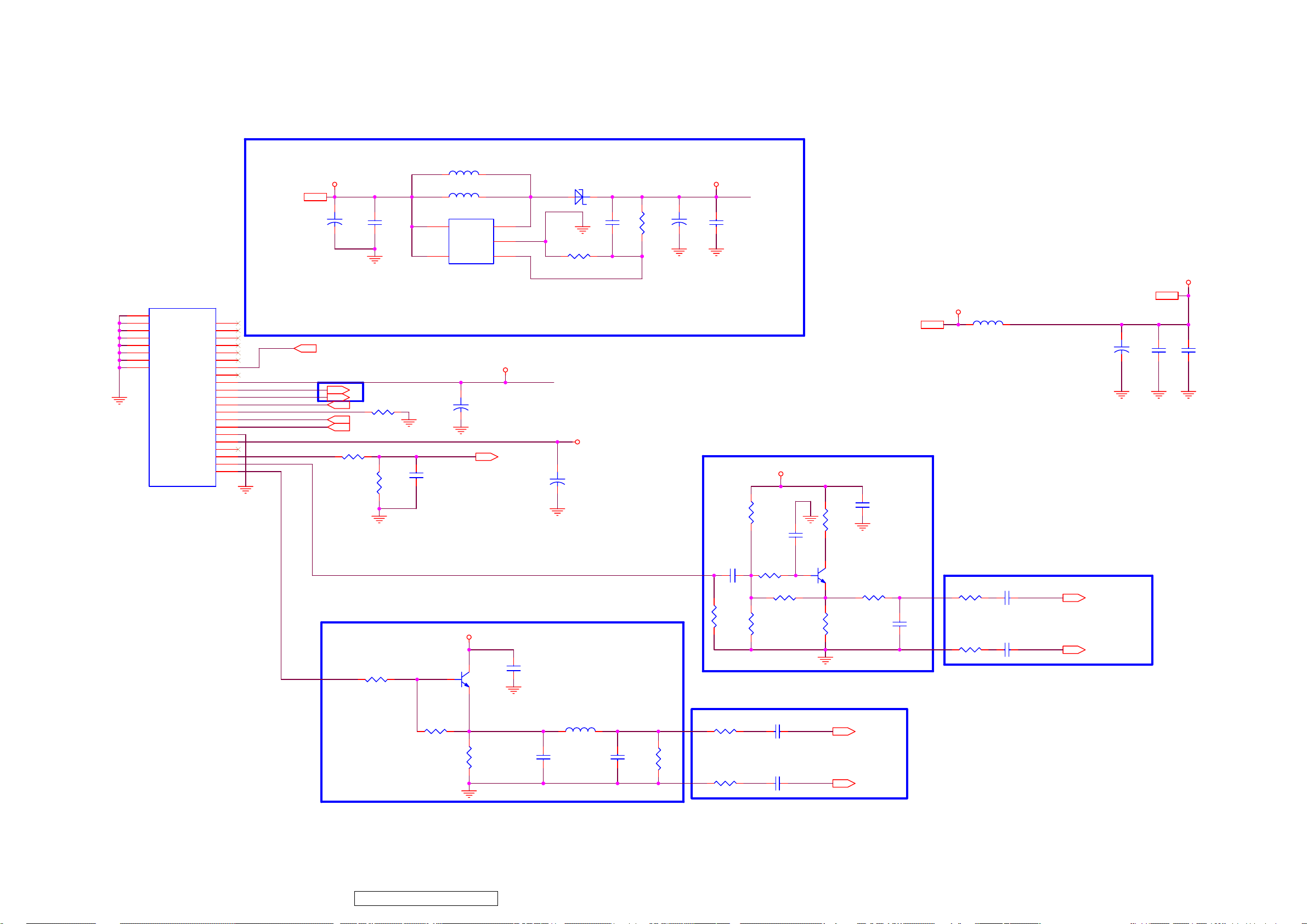
ViewSonic Corporation
67
VT2430-1M
8.3. CAM Tuner
I501
DTVS205EH201A
22
GND
23
GND
24
GND
25
GND
26
GND
27
GND
28
GND
29
GND
NC
NC
NC
NC
NC
NC
RF_AGC
NC
NC/VT
IF(+)
IF(-)
IF_AGC
IF_TP
SCL
SDA
GND
TU 5V
NC
AFT
SIF OUT
CVBS OUT
1
2
3
4
5
6
7
8
9
10
11
12
13
14
15
16
17
18
19
20
21
+5V_General2,3,8,10,15
+
RFAGC1
C137
470u/16V
RFAGC1 3
C140
100nF
I106
FP6736S5PTR SOT23-5/SMD
IF trace 15 mil ,Cover GND 12mil,GAP 6mil
IF+
IFIFAGC
IF_TP
SCLK
SDAT
CAM_Tuner-5V
Tuner-AFT
SIF_OUT
ATV-CVBS
IF+ 3
IF- 3
IFAGC 3
R502 NC
T_SCL 3
T_SDA 3
R501
100K
R503
100K
TUNER-SAR2
C501
100nF
Close to Tuner
R511
0R
ATV_CVBS
L112 10uH
L113 NC
5
V_IN
GND
+
C159
1u/50V
Tuner-5V
32
Q501
1
NC/MMBT3904
measure current
1
SW
2
34
FBSHDN
30VTU
TUNER-SAR2 6
C141
D103 SR36
100nF/0603
Ra
R127 11K5 1% 0603
Vout=VFB*(1+Ra/Rb)
VFB=1.25V
RB=0.7K~5Kohm
30VTU
Tuner-5V
+
C168
470u/16V
C510
NC
Rb
1u/50V/(4.7u)
R125
274K1% 0603
30VTU+5V_General
30VTU
+
C138
C142
100nF/0603
Close to Tuner
C506
10nF/0603
R591 0R
R586
NC/2K2
Close to Mstar IC
Tuner-5V
R504
47K
R587
R508
47K
SIF_Q-B
NC/0
1
C561
NC
R505
10R 0603
SIF_Q-C
32
Q502
MMBT3904
SIF_Q-E
R509
820R 0603
C505
100nF
R506
10R 0603
Tuner-5V
3
Tuner-5V
5VIF
5VIF2
L502 600R/1.5A 0805
C502
100uF/16V
C504
C503
+
100nF
1nF
SIF trace > 15 mil
Close to Mstar IC
SIF
C508
22pF
R507
47R
R510
47R
C507
100nF
C509
100nF
SIF_IN+
SIF_IN-
SIF_IN+ 6
SIF_IN- 6
R588
0R
R513
1K 0603
Confidential - Do Not Copy
L501
0R 0805
C512
NC/680pF
CVBS+
C513
NC/330pF
NC/75R
R514
R512
62R
R515
47R
C511
100nF
C514
100nF
TV_IN+
TV_IN-
TV_IN+ 6
TV_IN- 6
Page 71
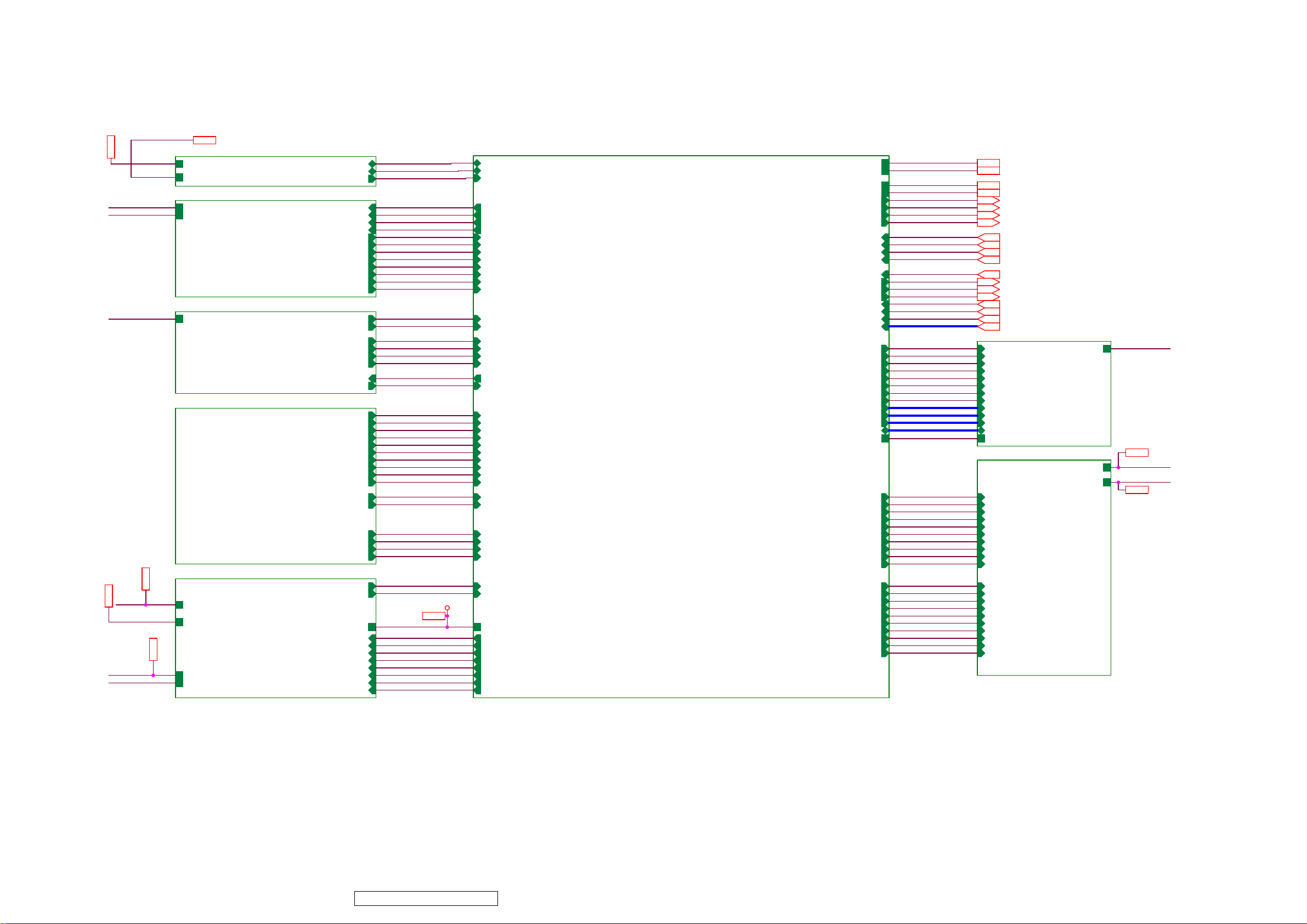
ViewSonic Corporation
68
VT2430-1M
8.4. MSD2248AL Block
VCC5V-ST 6,8,10,13,15
VCC5V-ST
+5V_General
VCC5V-ST
VCC3.3V-ST
VCC5V-ST
12V 2
VCC3.3V-ST 6.13
12V
VCC3.3V-ST
5VAMP 2
5VAMP
VCC5V-ST
+5V_General
15_USB
10_HDMI Interface
08_VGA
09_Video_Interface
2,14
VCC5V-ST
+5V_General
VCC5V-ST
VCC3.3V-ST
USB
HDMI
VGA
USB_OCD_N-GPIO123
HDMI-CEC
HPD_CTRL
DDC_SCL
DDC_SDA
HDMI-CLKP
HDMI-CLKN
HDMI-RX0P
HDMI-RX0N
HDMI-RX1P
HDMI-RX1N
HDMI-RX2P
HDMI-RX2N
VGA_HSYNC1VCC5V-ST
VGA_VSYNC1
RGB1_SOG
RGB1_RIN+
RGB1_GIN+
RGB1_BIN+
RGB0-SOG
RGB0_PB+
RGB0_PB-
RGB0_PR+
RGB0_PR-
Video Interface
CVBS1_IN
11-Audio_Block
PC_Audio-AUL2
PC_Audio-AUR2
12V
VCC3.3V-ST
Audio Block
5VAMP
VCC5V-ST MUTE_S/GPIO124
POWER-SAVING-GPIO98
POWER-ON/OFF-GPIO44
DTV-VDD33
AU_DACO_1L
AU_DACO_1R
AU_DACO_0L
AU_DACO_0R
SHUT_DOWN_AU
USB_DM
USB_DP
UART-TX
UART-RX
RGB0_Y+
RGB0_Y-
Y_CC
YIN_0+
CIN_0+
VCOM1
AUL0
AUR0
AUL1
AUR1
USB_DM
USB_DP
USB_OCD_N-GPIO123
HDMI-CEC
HPD_CTRL
DDC_SCL
DDC_SDA
HDMI-CLKP
HDMI-CLKN
HDMI-RX0P
HDMI-RX0N
HDMI-RX1P
HDMI-RX1N
HDMI-RX2P
HDMI-RX2N
VGA_HSYNC1
VGA_VSYNC1 TS_D[7:0]
RGB1-SOG
RGB1_RIN+
RGB1_GIN+
RGB1_BIN+
UART-TX
UART-RX
RGB0-SOG
RGB0_Y+
RGB0_YRGB0_PB+
RGB0_PBRGB0_PR+
RGB0_PRY_CC
YIN_0+
CIN_0+
CVBS1_IN
VCOM1
AUL0
AUR0
AUL1
AUR1
PC_Audio-AUL2
PC_Audio-AUR2
DTV-VDD333
DTV-VDD33
AU_DACO_1L
AU_DACO_1R
AU_DACO_0L
AU_DACO_0R
POWER-SAVING-GPIO98
SHUT_DOWN_AU
MUTE_S/GPIO124
POWER-ON/OFF-GPIO44
DTV-VDD33
06_MSD2248AL_256_IC
USB_DM
USB_DP
USB_OCD_N-GPIO123
HDMI-CEC
HPD_CTRL
HDMI-SCL
HDMI-SDA
HDMI-CLKP
HDMI-CLKN
HDMI-RX0P
HDMI-RX0N
HDMI-RX1P
HDMI-RX1N
HDMI-RX2P
HDMI-RX2N
VGA_HSYNC1
VGA_VSYNC1
RGB1-SOG
RGB1_RIN+
RGB1_GIN+
RGB1_BIN+
UART-TX
UART-RX
RGB0-SOG
RGB0_Y+
RGB0_YRGB0_PB+
RGB0_PBRGB0_PR+
RGB0_PRY_CC
YIN_0+
CIN_0+
CVBS1_IN
VCOM1
AUL0
AUR0
AUL1
AUR1
AUL2
AUR2
DTV-VDD33
AU_DACO_1L
AU_DACO_1R
AU_DACO_0L
AU_DACO_0R
POWER-SAVING-GPIO98
SHUT_DOWN_AU
MUTE_S/GPIO124
POWER-ON/OFF-GPIO44
MSD2248AL_256_IC
VCC5V-ST
VCC3.3V-ST
VCC2.5V-ST
POWER-ON/OFF-GPIO44
PANEL-ON/OFF-GPIO11
VCC1.2V-ST
BRI_ADJ-PWM2
VBLCTRL-GPIO12
TV_IN+
TV_IN-
SIF_IN+
SIF_IN-
TUNER-SAR2
I2C-SCL
I2C-SDA
DTVRESET
TS_CLK
TS_SYNC
TS_VALID
TS_D[7:0]
MCLK+
MCLK-
WEZ
DQS[3:0]
DQM[3:0]
MADR[12:0]
MDATA[31:0]
MDDR_VREF
RXE0-
RXE0+
RXE1-
RXE1+
RXE2RXE2+
RXEC-
RXEC+
RXE3RXE3+
RXO0RXO0+
RXO1RXO1+
RXO2RXO2+
RXOC-
RXOC+
RXO3RXO3+
VCC5V-ST
VCC3.3V-ST
VCC2.5V-ST
VCC1.2V-ST
POWER-ON/OFF-GPIO44
PANEL-ON/OFF-GPIO11
BRI_ADJ-PWM2
VBLCTRL-GPIO12
TV_IN+
TV_INSIF_IN+
SIF_IN-
TUNER-SAR2
I2C-SCL
I2C-SDA
DTVRESE
TS_CLK
TS_SYNC
TS_VALID
MCLK+
MCLKCKE
CKE
RAS
RAS
CAS
CAS
WEZ
BA0
BA0
BA1
BA1
DQS[3:0]
DQM[3:0]
MADR[12:0]
MDATA[31:0]
MDDR_VREF
T
RXE0RXE0+
RXE1RXE1+
RXE2RXE2+
RXECRXEC+
RXE3RXE3+
RXO0RXO0+
RXO1RXO1+
RXO2RXO2+
RXOCRXOC+
RXO3RXO3+
VCC5V-ST 2.13
VCC3.3V-ST 2
VCC2.5V-ST 2
VCC1.2V-ST 2
POWER-ON/OFF-GPIO44 2.13
PANEL-ON/OFF-GPIO11 2
BRI_ADJ-PWM2 2
VBLCTRL-GPIO12 2
TV_IN+ 4
TV_IN- 4
SIF_IN+ 4
SIF_IN- 4
TUNER-SAR2 4
I2C-SCL 3
I2C-SDA 3
DTVRESET 3
TS_CLK 3
TS_SYNC 3
TS_VALID 3
TS_D[7:0] 3
07_Memory
MCLK+
MCLKCKE
RAS
CAS
WEZ
BA0
BA1
DQS[3:0]
DQM[3:0]
MADR[12:0]
MDATA[31:0]
MDDR_VREF
14_LVDSx2 Panel
RXE0RXE0+
RXE1RXE1+
RXE2RXE2+
RXECRXEC+
RXE3RXE3+
RXO0RXO0+
RXO1RXO1+
RXO2RXO2+
RXOCRXOC+
RXO3RXO3+
Memory
LVDSx2
VCC2.5V-ST
PANEL-VCC
+5V_General
VCC2.5V-ST
PANEL-VCC 2
PANEL-VCC
+5V_General
+5V_General 2,3,4
Confidential - Do Not Copy
Page 72
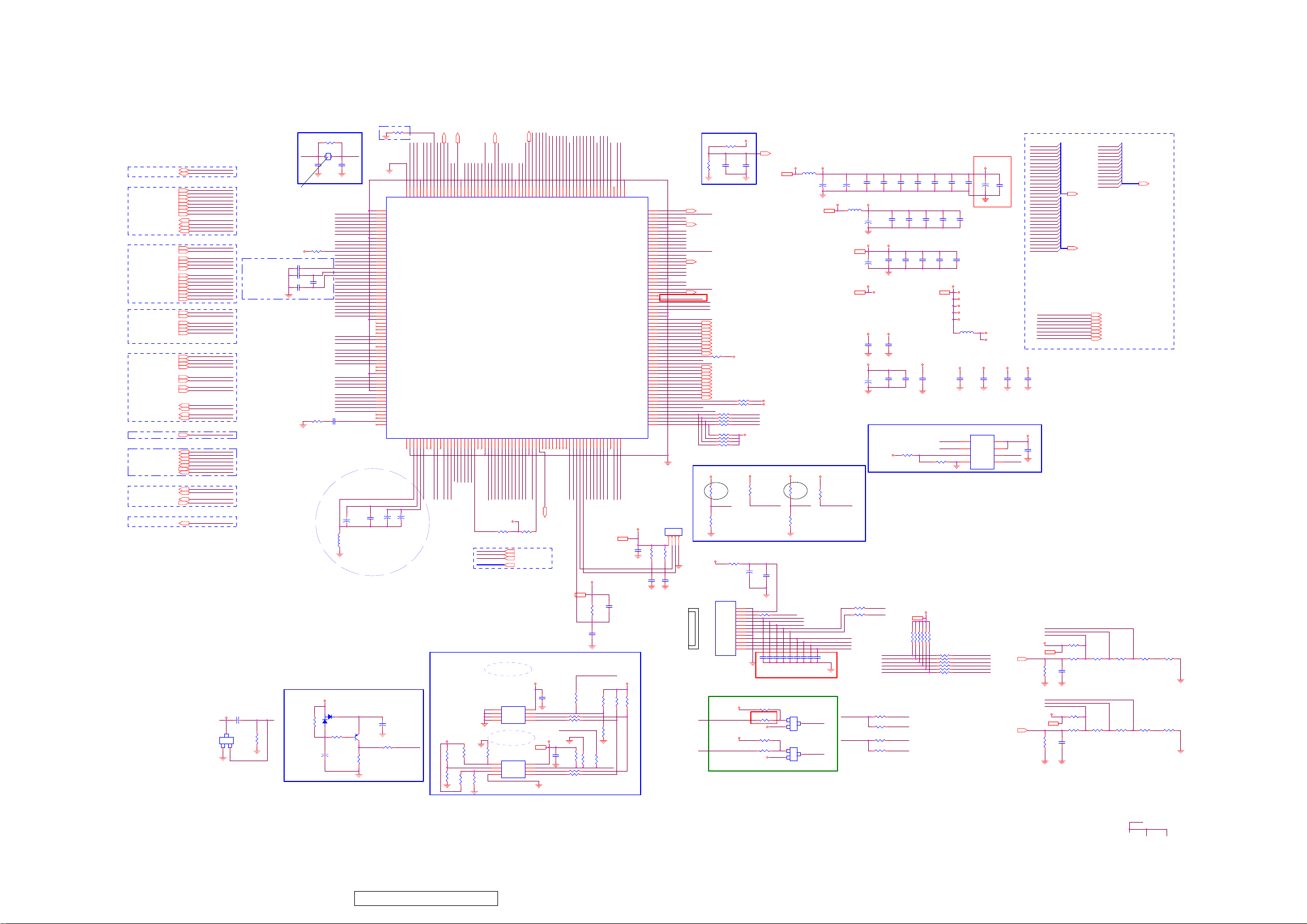
ViewSonic Corporation
69
VT2430-1M
8.5. MSD2248AL_256_IC
USB Block
HDMI Block
RGB Block
CVBS Block
Audio Block
SAR
GPIO
MUTE_S/GPIO12413
13
POWER-SAVING-GPIO98
SHUT_DOWN_AU13
PANEL-ON/OFF-GPIO112
USB_OCD_N-GPIO12315
POWER-ON/OFF-GPIO442,13
I2C / UART
PWM
13
VBLCTRL-GPIO122
BRI_ADJ-PWM22
USB_DP15
USB_DM15
HDMI-CLKP10
HDMI-CLKN10
HDMI-RX0P10
HDMI-RX0N10
HDMI-RX1P10
HDMI-RX1N10
HDMI-RX2P10
HDMI-RX2N10
HDMI-CEC10
HPD_CTRL10
HDMI-SDA10
HDMI-SCL10
VGA_HSYNC18
VGA_VSYNC18
RGB1-SOG8
RGB1_RIN+8
RGB1_GIN+8
RGB1_BIN+8
RGB0-SOG9
RGB0_Y+9
RGB0_Y-9
RGB0_PB+9
RGB0_PB-9
RGB0_PR+9
RGB0_PR-9
Y_CC9
YIN_0+9
CIN_0+9
CVBS1_IN9
VCOM19
TV_IN+4
TV_IN-4
SIF_IN+4
SIF_IN-4
AU_DACO_0L13
AU_DACO_0R
AU_DACO_1L13
AU_DACO_1R13
TUNER-SAR24
I2C-SCL3
I2C-SDA3
UART-TX8
UART-RX8
AUL09
AUR09
AUL212
AUR212
AUL19
AUR19
USB_DP
USB_DM
HDMI-CLKP
HDMI-CLKN
HDMI-RX0P
HDMI-RX0N
HDMI-RX1P
HDMI-RX1N
HDMI-RX2P
HDMI-RX2N
HDMI-CEC
HPD_CTRL
HDMI-SDA
HDMI-SCL
VGA_HSYNC1
VGA_VSYNC1
RGB1-SOG
RGB1_RIN+
RGB1_GIN+
RGB1_BIN+
RGB0-SOG
RGB0_Y+
RGB0_YRGB0_PB+
RGB0_PBRGB0_PR+
RGB0_PRY_CC
YIN_0+
CIN_0+
CVBS1_IN
VCOM1
TV_IN+
TV_IN-
SIF_IN+
SIF_INAUL0
AUR0
AUL2
AUR2
AUL1
AUR1
AU_DACO_0L
AU_DACO_0R
AU_DACO_1L
AU_DACO_1R
TUNER-SAR2
MUTE_S/GPIO124
POWER-SAVING-GPIO98
SHUT_DOWN_AU
PANEL-ON/OFF-GPIO11
VBLCTRL-GPIO12
USB_OCD_N-GPIO123
POWER-ON/OFF-GPIO44
I2C-SCL
I2C-SDA
UART-TX
UART-RX
BRI_ADJ-PWM2
VCC3.3V-ST
C312 NC/10u/16V
V
+
23
SOT
RG
132
NC/LM810 2.65V
NC/24K
I210
Close to IC
as close
as possible
with width trace
SYS_RST
R302
System Crystal
XTALI
CL=20pF ; C0max=5pF
R262 390R 1% 0603
AVDD_ADC
C283
100nF
C284
100nF
C286
100nF
R355 0R
System Reset
R292
10K
R258
1M
X202
12MHz
C260
20pF
C285
NC
0R 0805
VCC3.3V-ST
3
1
D204
BAV99
L208
C315
R303
1K
10u/16V
C301
100nF
XTALO
C261
20pF
HDMI-CLKN
HDMI-CLKP
HDMI-RX0N
HDMI-RX0P
AVDD_ADC
HDMI-RX1N
HDMI-RX1P
HDMI-RX2N
HDMI-RX2P
HPD_CTRL
HDMI-REXT
HDMI-SDA
HDMI-SCL
VGA_HSYNC1
VGA_VSYNC1
VCLP
REFP
REFM
RGB1_BIN+
RGB1-SOG
RGB1_GIN+
RGB1_RIN+
RGB0_PBRGB0_PB+
RGB0_YRGB0_Y+
RGB0-SOG
RGB0_PRRGB0_PR+
AVDD_ADC
CIN_0+
YIN_0+
Y_CC
CVBS1_IN
VCOM1
TV_IN+
TV_INAVDD_ADC
AVDD_SIF
SIF_IN+
SIF_INVDDC
AUL0
AUR0
AUL1
AUR1
AUL2
AUR2
2
AUCOM
C304
+
C303
100nF
10u/16V
Close to IC
with width trace
Q203
1
MMBT3906
3 2
SYS_RST System-RST
R311
10K
1
2
3
4
5
6
7
8
9
10
11
12
13
14
15
16
17
18
19
20
21
22
23
24
25
26
27
28
29
30
31
32
33
34
35
36
37
38
39
40
41
42
43
44
45
46
47
48
49
50
51
52
53
55
56
57
58
59
60
61
62
63
64
+
R307
100R 0603
R257
909R 1% 0603
GND
RXCN
RXCP
RX0N
RX0P
AVDD_ADC
RX1N
RX1P
GND
RX2N
RX2P
GPIO125
REXT
DDCDA_DA
DDCDA_CK
HSYNC1
VSYNC1
VCLP
REFP
REFM
BIN1P
SOGIN1
GIN1P
RIN1P
BIN0M
BIN0P
GIN0M
GIN0P
SOGIN0
RIN0M
RIN0P
AVDD_ADC
GND
HSYNC0
VSYNC0
C1(CVBS7P)
Y1(CVBS5P)
C0(CVBS6P)
Y0(CVBS4P)
CVBS3P
CVBS2P
CVBS1P
VCOM1
CVBS0P
VCOM0
AVDD_ADC
NC
CVBSOUT
GND
AVDD_SIF
SIF_IN1P
SIF_IN1M
VDDC
GND
LINE_IN_0L
LINE_IN_0R
LINE_IN_1L
LINE_IN_1R
LINE_IN_2L
LINE_IN_2R
LINE_IN_3L
LINE_IN_3R
AUCOM
NC
+
C305
1u/50V
C313
47u/16V
AUVRM
AUVRP
AUVAG
+
10u/16V
AVDD_MPLL
256
257
GND
NC
6570666869
C306
XTALI
255
AVDD_MPLL
GND
67
AUVRM
XTALO
OTG_REXT
USB_DP
USB_DM
AVDD_OTG
254
249
251
252
250
253
XIN
GND
XOUT
USB_DP
USB_DM
AVDD_OTG
LINE_OUT_2L
LINE_OUT_2R
AVDD_AU
AUVRP
AUVAG
AUVRM
73
71
72
AUVRP
AUVAG
AU_DACO_1L
AVDD_AU
7
DQM07DQS0
AVDDL_DVI
AVDD_DDR
VDDC
DQS0
MDATA5
MDATA4
MDATA3
MDATA2
MDATA1
MDATA0
242
243
244
24589246
248
247
AVDD_DVI
USB_REXT
LINE_OUT_1R(DACO_S)NCLINE_OUT_0L(DACO_L)
LINE_OUT_1L
74757654808182838485868788
AU_DACO_1R
237
238
239
240
241
GND
VDDC
VDD_DDR
DDR_DQ[4]
DDR_DQ[3]
DDR_DQ[2]
DDR_DQ[1]
DDR_DQ[0]
DDR_DQS[0]
DDR_DQM[0]
GPIO20
VDDP
GPIO21
GPIO22
GPIO23
GPIO24
GPIO25
LINE_OUT_0R(DACO_R)
78
79
77
GPIOUP
GPIOINC
GPIODEC
GPIODOWN
GPIOMENU
GPIOENTER
SHUT_DOWN_AU
AU_DACO_0L
AU_DACO_0R
VDDP
Transport Stream
EEPROM
R331
R310
NC
4.7K
R333
R334
NC
NC
DQM1 7
AVDD_DDR
MDATA8
MDATA9
MDATA7
MDATA6
232
233
235
236
234
VDD_DDR
DDR_DQ[9]
DDR_DQ[8]
DDR_DQ[7]
DDR_DQ[6]
DDR_DQ[5]
VDDC
TSDATA[0]
GPIO26
GPIO27
GPIO28
GND
9091929394959697101
TS_D0
VDDC
VCC3.3V-ST
TS_CLK
TS_SYNC
TS_VALI
D
TS_D[7:0]
R332
NC
R335
0R
VDDC
AVDD_DDR
DQM1
MDATA15
MDATA14
MDATA13
MDATA12
MDATA11
MDATA10
222
230
223
224
226
227
225
228
229
231
GND
VDDC
DDR_DQ[15]
DDR_DQ[14]
DDR_DQ[13]
DDR_DQ[12]
DDR_DQ[11]
DDR_DQ[10]
DDR_DQM[1]
I206
MSD2248AL
TSDATA[1]
TSDATA[2]
TSDATA[3]
TSDATA[4]
TSDATA[5]
TSDATA[6]
TSDATA[7]
TSVALID
TSSYNC
9899100
TS_VALID
TS_D5
TS_D7
TS_D4
TS_SYNC
TS_D3
TS_CLK
TS_D6
TS_D1
TS_D2
R272 4.7K
R318 4.7K
TS_CLK 3
TS_SYNC 3
TS_VALID 3
TS_D[7:0] 3
I2C address
at A0.
I209NC/24C512K
1
A0
VCC
2
A1
WP
3
A2
SCL
4 5
GND SDA
I2C address
at A4
VCC3.3V-ST2
I211
24C04
1
A0
VCC
2
A1
WP
3
A2
SCL
4 5
GND SDA
DQS1 7
CAS
WEZ
RAS
BA0
BA1
DQS1
MADR12
MADR11
MADR10
217
218
219
220
216
213
214
215
221
VDD_DDR
DDR_BA[0]
DDR_BA[1]
DDR_WE_N
DDR_AD[11]
DDR_AD[12]
DDR_DQS[1]
DDR_RAS_N
DDR_CAS_N
GND
VDDC
TSCLK
GPIO44/I2S_IN_WS
GPIO45/I2S_IN_BCK
I2S_IN_SD
SPDIF_IN
SPDIF_OUT
I2S_OUT_WS
102
103
104
105
106
107
108
109
DTVRESET
VDDC
POWER-ON/OFF-GPIO44
DTVRESET 3
VCC3.3V-ST2,10
VCC3.3V-ST
C311
100nF
8
7
24C32_I2C-SCL I2C-SCL
6
24C32_I2C-SDA
VCC3.3V-STVCC3.3V-ST
8
7
24C04_I2C-SCL
6
24C04_I2C-SDA
AVDD_DDR
MADR8
MADR7
MADR5
MADR6
MADR9
207
208
209
210
211
212
VDD_DDR
DDR_AD[7]
DDR_AD[8]
DDR_AD[9]
DDR_AD[5]
DDR_AD[6]
DDR_AD[10]
I2S_OUT_MCK
I2S_OUT_SCK
I2S_OUT_SD0
I2S_OUT_MUTE
VDDP
IRIN
INT
110
111
112
113
114
115
OSD-POWER-KEY
IR-SYNC
VDDP
EEPROM_WPN-GPIO13
R290 100R
R293 100R
EEPROM_WPN-GPIO13
R336
C316
100nF
4.7K
R312 100R
R313 100R
MADR3
MADR4
205
206
DDR_AD[4]
UART_TX(DDCA_DAT)
117
116
UART-RX
UART-TX
VCC3.3V-ST
R338
100R
MADR2
204
DDR_AD[3]
UART_RX(DDCA_CLK)
118
SAR0
I2C-SDA
R337
NC
C348
100nF
4M
8
7
SPI_SCK
6
SPI_SDI
SAR1
SAR0
DDR-SDRAM Block
AVDD_SIFAVDD_AU
C299
C298
100nF
100nF
VCC3.3V-ST
C302
100nF
VCC3.3V-ST
VCC3.3V-ST2,10
SAR1
R284
2.4K
VCC3.3V-ST2,10
SAR0
R304
2.4K
MDATA31
MDATA30
MDATA29
MDATA28
MDATA27
MDATA26
MDATA25
MDATA24
MDATA23
MDATA22
MDATA21
MDATA20
MDATA19
MDATA18
MDATA17
MDATA16
MDATA15
MDATA14
MDATA13
MDATA12
MDATA11
MDATA10
MDATA9
MDATA8
MDATA7
MDATA6
MDATA5
MDATA4
MDATA3
MDATA2
MDATA1
MDATA0
OSDUP
OSDDOWN
OSDENTER
OSDINC
OSDDEC
OSDMENU
VCC3.3V-ST
CKE
MCLK+
MCLKCAS
RAS
WEZ
BA0
BA1
MADR12
MADR11
MADR10
MADR9
MADR8
MADR7
MADR6
MADR5
MADR4
MADR3
MADR2
MADR1
MADR0
MDATA[16..31]
7
MDATA[0..15]
7
CKE
MCLK+
MCLKCAS
RAS
WEZ
BA0
BA1
R278 1K
0V
1V 3V2V
R280
R279
1K
C310
100nF
R289 1K
0V 3V2V1V
R296
1K
C314
100nF
R297
R281
220R 0603
R298
220R 0603
470R 0603
470R 0603
MADR[0..12]
7
7
7
7
7
7
7
7
7
R282
R283
1K
5K1
R299
R300
1K
5K1
AVDD_DDR
R263
1K 1%
MDDR_VREF
C289
100nF
R264
EEPROM_WPN-GPIO13
VDDC
MDDR_VREF
AVDD_MEMPLL
MCLK-
MCLK+
CKE
MADR1
MADR0
193
194
195
196
197
198
199
200
201
202
203
GND
VDDC
MVREF
DDR_DQS[2]
DDR_CKE
DDR_CKO
DDR_AD[0]
DDR_AD[1]
DDR_AD[2]
SAR0/FDSP_IMS/MCU_TMS
SAR1/FDSP_ICLK/MCU_TCK
SAR2/FDSP_IDI/MCU_TDI
119
120
121
VDD_DDR
DDR_CKO_N
DDR_DQ[16]
AVDD_MEMPLL
DDR_DQ[17]
DDR_DQM[2]
GPIO14/UART_TX1
DDR_DQ[18]
GPIO13/UART_RX1/CEC
DDR_DQ[19]
DDR_DQ[20]
DDR_DQ[21]
DDR_DQ[22]
DDR_DQ[23]
VDD_DDR
DDR_DQ[24]
DDR_DQ[25]
DDR_DQM[3]
DDR_DQ[26]
DDR_DQ[27]
DDR_DQ[28]
DDR_DQ[29]
DDR_DQ[30]
DDR_DQ[31]
VDD_DDR
DDR_DQS[3]
GPIO97
GPIO98
GPIO99
GPIO100
AVDD_LPLL
LB0N/RXO0-
LB0P/RXO0+
LB1N/RXO1-
LB1P/RXO1+
LB2N/RXO2-
LB2P/RXO2+
LBCKN/RXOC-
LBCKP/RXOC+
LB3N/RXO3-
LB3P/RXO3+
GPIO11
GPIO12
LA0N/RXE0-
LA0P/RXE0+
LA1N/RXE1-
LA1P/RXE1+
LA2N/RXE2-
LA2P/RXE2+
LACK/RXECLACK/RXEC+
LA3N/RXE3-
LA3P/RXE3+
GPIO123
GPIO124
GPIO125/CEC
SPI_CZ0
SPI_DO
SAR3/FDSP_IDO/MCU_TDO
PWM0
122
SPI_CK
PWM1
PWM2
PWM3
HWRESET
DDCR_DA
DDCR_CK
123
124
125
128
126
127
SPI_DI
VDDC
VDDP
VDDP
GND
GND
GND
GND
192
191
190
189
188
187
186
185
184
183
182
181
180
179
178
177
176
175
174
173
172
171
170
169
168
167
166
165
164
163
162
161
160
159
158
157
156
155
154
153
152
151
150
149
148
147
146
145
144
143
142
141
140
139
138
137
136
135
134
133
132
131
130
129
DQS2
AVDD_DDR
MDATA16
MDATA17
DQM2
MDATA18
MDATA19
MDATA20
MDATA21
MDATA22
MDATA23
AVDD_DDR
MDATA24
MDATA25
DQM3
MDATA26
MDATA27
MDATA28
MDATA29
MDATA30
MDATA31
AVDD_DDR
DQS3
POWER-SAVING-GPIO98
LED_R-GPIO99
LED_B-GPIO100
VDDC
AVDD_LPLL
RXO0RXO0+
RXO1RXO1+
RXO2RXO2+
RXOCRXOC+
RXO3-
RXO3+
PANEL-ON/OFF-GPIO11
VBLCTRL-GPIO12
VDDP
RXE0-
RXE0+
RXE1-
RXE1+
RXE2-
RXE2+
RXEC-
RXEC+
RXE3-
RXE3+
USB_OCD_N-GPIO123
MUTE_S/GPIO124
HDMI-CEC
VDDP
SPI-CSN0
SPI-SDO
SPI-SDI
SPI-SCK
1K 1%
DQS2
7
DQM2
7
DQM3
7
DQS3
7
in order to reduce power comsumption add GPIO to control AMP sleep mode 080901
RXO0- 14
RXO0+ 14
RXO1- 14
RXO1+ 14
RXO2- 14
RXO2+ 14
RXOC- 14
RXOC+ 14
RXO3- 14
RXO3+ 14
VCC3.3V-ST
R261 4.7K
RXE0- 14
RXE0+ 14
RXE1- 14
RXE1+ 14
RXE2- 14
RXE2+ 14
RXEC- 14
RXEC+ 14
RXE3- 14
RXE3+ 14
R260 4.7K
R360 4.7K
R721 100R
R722 100R
R723 100R
R724 100R
R725 NC/4K7
R726 NC/4K7
R727 NC/4K7
R728 NC/4K7
Mode Selection
VCC3.3V-ST
I2C-SCL
I2C-SDA
PWM1
BRI_ADJ-PWM2
PWM0
System-RST
SAR1
TUNER-SAR2
FLASH0_WPN-SAR3
Debug port
P203
VCC5V-ST
VCC5V-ST2,13
C300
100nF
UART-TX
UART-RX
C200
100nF
R317
10K
C254
100nF
VCC3.3V-ST
R287
R286
R285
4.7K
4.7K
4.7K
R301
NC
R339
100R
SIP4
2.0mm/Male_wafer
123
4
R151
R152
NC
NC
C151
C152
NC
NC
R268
NC/10K
PWM0
R270
10K
VCC5V-ST
R275 100R 0603
C308
10u/16V
P204
13
IRGND
12
IR5V
1
13
11
IRIN
10
RIGHT
9
LEFT
8
POWER
7
LEDR
6
LEDG
5
GND
4
MENU
3
UP
2
DOWN
1
SEL
JST-PH13P-2.0-90
modify Res value from 5K6 to 6K8 080910
VCC5V-ST
LED_B-GPIO100
VCC5V-ST
LED_R-GPIO99
MDDR_VREF
7
VCC1.2V-ST
VDDC
L205
600R/1.5A 0805
+
10u/16V
VCC3.3V-ST2
VCC3.3V-ST
VCC3.3V-ST
R356
10K
R271
NC/1K
PWM1
VBLCTRL-GPIO12
R358
NC/10K
IR-SYNC
OSDINCJEAN
OSDDEC
OSD-POWER-KEY
C3321nF
C3291nF
C3251nF
C3311nF
C333
1nF
C3281nF
C3301nF
relayout bypass cap link GND position from via to board side GND 081014
LED Driver
1
B
LEDB
SOT
3
C
23
2
E
Q201
MMBT3906
1
B
LEDR
SOT
3
C
23
2
E
Q202
MMBT3906
INTERFACE
SPI_CSN0
SP_SDO
SPI_SDI
SPI_SCK
VCC3.3V-ST
VCC3.3V-ST
C290
1nF
PANEL
R269
1K
BRI_ADJ-PWM2
C309
100nF
C3261nF
R288 2K2
R294 6K8
VCC5V-ST
R305 2K2
R308 5K6
VCC5V-ST
VCC1.2V-ST2
VCC3.3V-ST
VCC3.3V-ST
R340 100R
C3271nF
C264
+
C262
C263
100nF
10u/16V
VCC3.3V-ST VDDP
L206
600R/1.5A 0805
+
C271
10u/16V
VCC2.5V-ST
VCC2.5V-ST2,7
+
C277
10u/16V
VCC3.3V-ST
VCC3.3V-ST2
AVDD_OTG AVDD_MPLL
C287
100nF
AVDD_ADC AVDD_DVI
+
C291
10u/16V
Boot Loader SPI Flash
VCC3.3V-ST
R276 470R 0603
R277 3K9
OSDMENU
OSDUP
OSDDOWNJEAN
OSDENTER
R291 0 0603
OSDINCJEAN
R295 NC/0 0603
R306 0 0603
OSDDOWNJEAN OSDDOWN
R309 NC/0 0603
R295 , R309 ------ JEAN STD
R291 , R306 ------ CUSTOMER
C266
C265
100nF
100nF
C273
C272
100nF
100nF
AVDD_DDR
C278
C279
100nF
100nF
AVDD_MPLL
VCC3.3V-ST2
C288
100nF
Using power plane
C293
C292
100nF
100nF
*100MHz, No any VIA hole !
R266
NC/4.7K
LEDR
LEDB
VCC3.3V-ST2
R71110K
OSDUP
OSDDOWN
OSDENTER
OSDINC
OSDDEC
OSDMENU
OSDINC
OSDDOWN
OSDINC
C267
100nF
FLASH0_WPN-SAR3
VCC3.3V-ST
R71310K
R71410K
R71210K
C268
100nF
C274
100nF
C280
C281
100nF
100nF
VCC3.3V-ST
C294
100nF
Close to Scaler
SPI_CSN0
SP_SDO
R267
10K
R71510K
R71610K
R701 NC
R702 NC
R703 NC
R704 NC
R705 NC
R706 NC
modify circuit 080710
AVDDL_DVI
C270
C269
100nF
100nF
C275
C276
100nF
100nF
C282
100nF
AVDD_LPLL
AVDD_MEMPLL
AVDD_AU
AVDD_SIF
AVDD_OTG
L207
600R/1.5A 0805
AVDD_LPLL
AVDD_MEMPLL
C296
100nF
I207
MX25L2305DM2I-12G
1
CE#
2
SO
HOLD#
3
WP#
4 5
VSS SI
GPIOUP
GPIODOWN
GPIOENTER
GPIOINC
GPIODEC
GPIOMENU
+
C349
10u/16V
AVDD_ADC
AVDD_DVI
C297
100nF
VDD
SCK
MDDR_VREF
Confidential - Do Not Copy
Page 73
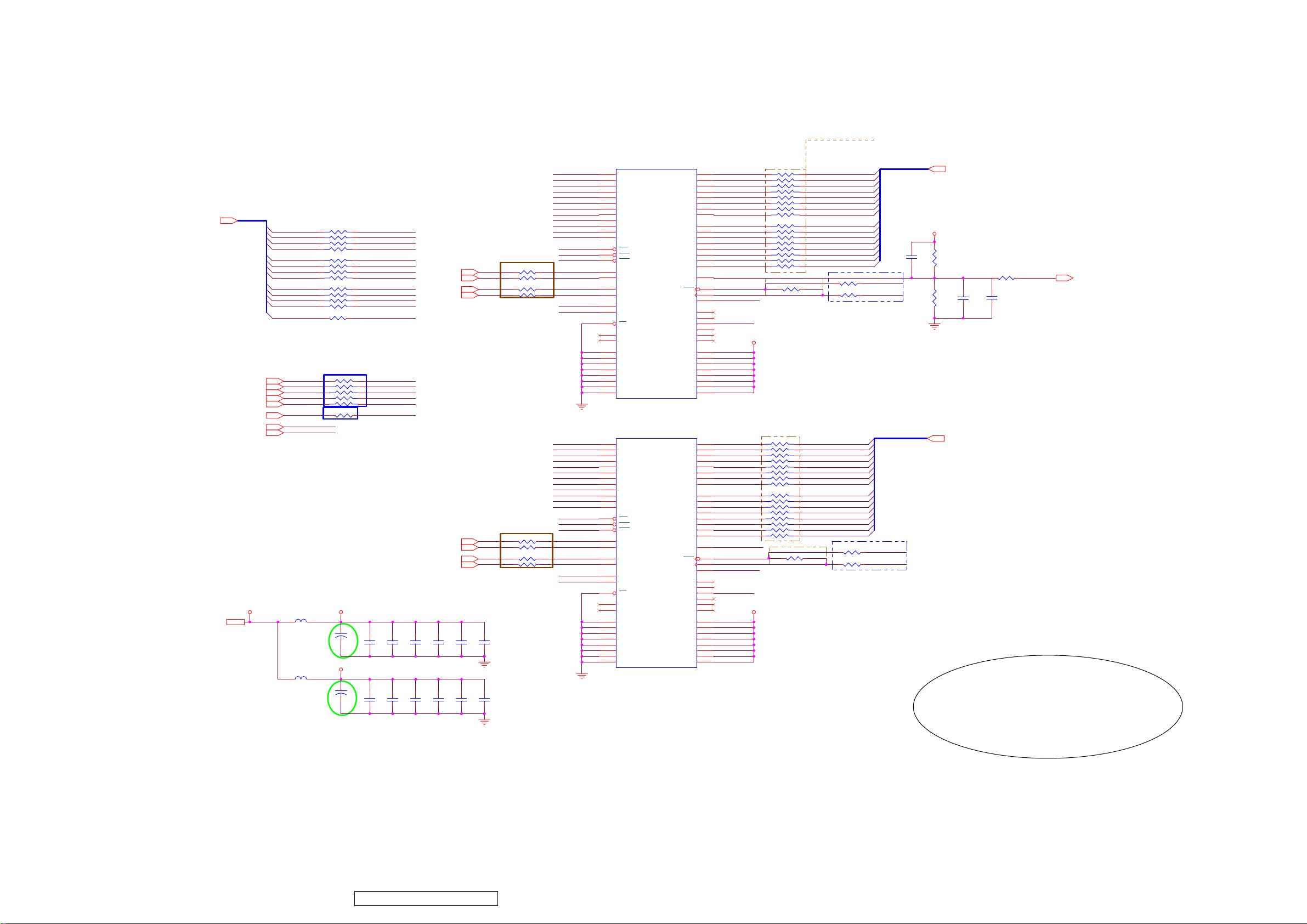
ViewSonic Corporation
70
VT2430-1M
8.6. DDR1
Middle of DRAM and MStar
I201
MADR_AD0
MADR_AD1
MADR_AD2
MADR_AD3
MADR_AD5
MADR_AD6
MADR_AD7
6
MADR[0..12]
6
6
6
6
6
6
6
6
BA1
BA0
WEZ
RAS
CAS
CKE
MCLK+
MCLK-
RP21 RP56X4
MADR0
MADR1
MADR2
MADR3
RP23 RP56X4
MADR4
MADR5
MADR6
MADR7
RP25 RP56X4
MADR8
MADR9
MADR10
MADR11
MADR12
R347 56R
Close to MStar IC
BA1
RP32 RP56X4
BA0
WEZ
RAS
CAS
CKE
MCLK+
MCLK-
1234
8765
1234
8765
1234
8765
R202 56R
1234
8765
R212 22R
Close to MStar IC
MADR_AD0
MADR_AD1
MADR_AD2
MADR_AD3
MADR_AD4
MADR_AD5
MADR_AD6 LDQS0
6
MADR_AD7
MADR_AD8
MADR_AD9
MADR_AD10
MADR_AD11
MADR_AD12
M_BA1
M_BA0
M_WE
M_RAS
M_CAS
M_CKE
6
6
6
6
DQS1
6
DQS0
6
DQM1
6
DQM0
DQS3
DQS2
DQM3
DQM2
R205 27R
DQS1
R206 27R
DQS0
R208 33R
DQM1
R210 33R
DQM0
Close to DDR-SDRAM
DQS3
R348 27R
R349 27R
DQS2
DQM3
R350 33R
R351 33R
DQM2
Close to DDR-SDRAM
VCC2.5V-ST
VCC2.5V-ST2,6
Z=120ohm/0603 3A
L0603
Z=120ohm/0603 3A
L0603
+2.6MVDD1 +2.6MVDD2
L215
100uF/16V
+2.6MVDD2
L216
100uF/16V
EC57 / EC58 Change to 100uF
Reduce Ripple 200mV to
100mV
C201
C203
100nF
C202
C209
100nF
C204
100nF
C210
100nF
C205
100nF
C343
100nF
C206
100nF
C344
100nF
C207
100nF
C345
100nF
C208
100nF
C346
100nF
MADR_AD8
MADR_AD9
MADR_AD10
MADR_AD11
M_WE
M_CAS
M_RAS
UDQS0
LDQM0
UDQM0
M_BA0
M_BA1
MADR_AD0
MADR_AD1
MADR_AD2
MADR_AD3
MADR_AD4
MADR_AD6
MADR_AD7
MADR_AD8
MADR_AD9
MADR_AD10
MADR_AD11
M_WE
M_CAS
M_RAS
LDQS1
UDQS1
LDQM1
UDQM1
M_BA0
M_BA1
DDR_128Mb_TSOP66
29
A0
30
A1
31
A2
32
A3
35
A4
36
A5
37
A6
38
A7
39
A8
40
A9
28
A10/AP
41
A11
21
WE
22
CAS
23
RAS
16
LDQS
51
UDQS
20
LDM
47
UDM
26
BA0
27
BA1
24
CS
14
NC
17
NC
34
VSS
48
VSS
66
VSS
6
VSSQ
12
VSSQ
52
VSSQ
58
VSSQ
64
VSSQ
DQ0
DQ1
DQ2
DQ3
DQ4
DQ5
DQ6
DQ7
DQ8
DQ9
DQ10
DQ11
DQ12
DQ13
DQ14
DQ15
VREF
CLK
CLK
CKE
MVDD
MVDD
MVDD
VDDQ
VDDQ
VDDQ
VDDQ
VDDQ
2
4
5
7
8
10
11
13
54
56
57
59
60
62
63
65
49
46
45
44
19
NC
25
NC
42
NC
43
NC
50
NC
53
NC
1
18
33
3
9
15
55
61
2M X 16bit X 4BK
I212
DDR_128Mb_TSOP66
29
A0
30
A1
31
A2
32
A3
35
A4
36
A5
37
A6
38
A7
39
A8
40
A9
28
A10/AP
41
A11
21
WE
22
CAS
23
RAS
16
LDQS
51
UDQS
20
LDM
47
UDM
26
BA0
27
BA1
24
CS
14
NC
17
NC
34
VSS
48
VSS
66
VSS
6
VSSQ
12
VSSQ
52
VSSQ
58
VSSQ
64
VSSQ
DQ0
DQ1
DQ2
DQ3
DQ4
DQ5
DQ6
DQ7
DQ8
DQ9
DQ10
DQ11
DQ12
DQ13
DQ14
DQ15
VREF
CLK
CLK
CKE
MVDD
MVDD
MVDD
VDDQ
VDDQ
VDDQ
VDDQ
VDDQ
2
4
5
7
8
10
11
13
54
56
57
59
60
62
63
65
49
46
45
44
19
NC
25
NC
42
NC
43
NC
50
NC
53
NC
1
18
33
3
9
15
55
61
2M X 16bit X 4BK
RP22 RP22X4
DATA15
DATA14
DATA13
DATA12
RP24 RP22X4
DATA11MADR_AD4
DATA10
DATA9
DATA8
RP26 RP22X4
DATA7
DATA6
DATA5
DATA4
RP27 RP22X4
DATA3
DATA2
DATA1
DATA0
MVREF
CLKN0
M_CKE
MADR_AD12
+2.6MVDD1
Middle of DRAM and MStar
RP28 RP22X4
DATA31
DATA30
DATA29
DATA28
RP29 RP22X4
DATA27
DATA26MADR_AD5
DATA25
DATA24
RP30 RP22X4
DATA23
DATA22
DATA21
DATA20
RP31
DATA19
DATA18
DATA17
DATA16
MVREF
CLKN1
M_CKE
MADR_AD12
8765
1234
8765
1234
8765
1234
8765
1234
Close to DRAM
R209 300R 1%
8765
1234
8765
1234
8765
1234
RP22X4
8765
1234
Close to DRAM
R353 300R 1%
MDATA15
MDATA14
MDATA13
MDATA12
MDATA11
MDATA10
MDATA9
MDATA8
MDATA7
MDATA6
MDATA5
MDATA4
MDATA3
MDATA2
MDATA1
MDATA0
R207 22R
R211 22R
Close to Mstar IC
MDATA31
MDATA30
MDATA29
MDATA28
MDATA27
MDATA26
MDATA25
MDATA
MDATA23
MDATA22
MDATA21
MDATA20
MDATA19
MDATA18
MDATA17
MDATA16
R352 22R
R354 22R
Close to Mstar IC
24
MDATA[0..15]
MCLKMCLK+CLK0
MDATA[16..31]
MCLKMCLK+CLK1
VCC2.5V-ST
C347
NC/100nF
MDATA[0..15]
R215
1K 1%
R216
1K 1%
MDATA[16..31]
6
R364 NC/0R
C211
100nF
6
C212
1nF
Qimonda
HYB25DC256163CE-4(16X16)
MDDR_VREF
6
Confidential - Do Not Copy
Page 74
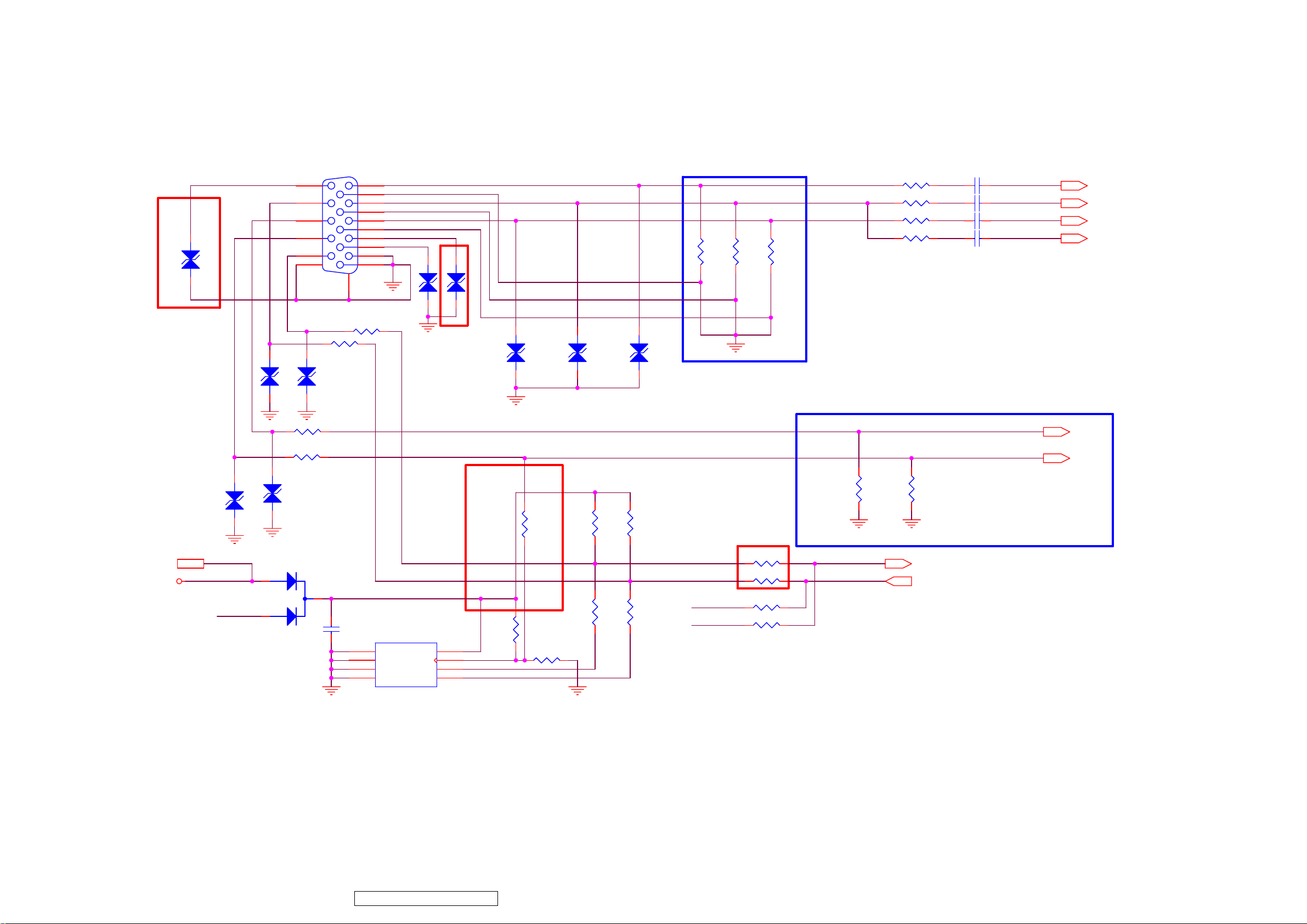
ViewSonic Corporation
71
VT2430-1M
8.7. VGA
D526
4.7P
add D525,D526 make a ESD protect 081014
VGA_VSYNC
VGA-TX
VGA_HSYNC
P502
DSUB-15
11
12
13
14
15
R554 100R
1
6
2
7
3
8
4
9
5
1016
17
R553 100R
VGA-RX
VGA5V
D506
4.7P
D525
4.7P
R-
G-
B-
D509
D510
D511
Close to VGA
R543
75R
R544
75R
R545
75R
VGA_RIN+
VGA_GIN+
VGA_BIN+
R539 47R
R540 47R
R541 47R
R542 470R
C516 47nF
C517 47nF
C518 47nF
C519 1nF
RGB1_RIN+
RGB1_GIN+
RGB1_BIN+
RGB1_SOG
RGB1_RIN+ 6
RGB1_GIN+ 6
RGB1_BIN+ 6
RGB1_SOG 6
6,8,13,15
VCC5V-ST
VCC5V-ST
D512
4.7P
VGA5V
D514
BAT54C
D507
4.7P
R546
510R
R547
510R
D513
4.7P
D508
4.7P
C520
100nF
I503
24C21
1
NC
2
NC
3
NC
4 5
GND SDA
4.7P
4.7P
4.7P
modify pull high voltage from +5V_General to VGA5V 080515
R552
4.7K
R556
100R
R589 0R
R590 0R
VGA-TX
VGA-RX
IIC make a difference for EDID and ISP 081014
R557 NC/100R
R559 NC/100R
VCC
VCLK
SCL
DDC_SCL_D
DDC_SDA_D
8
VGA-VCLK
7
VGA-SCL
6
VGA-SDA
NC
R558
R550
100R
R560
10K
R551
4.7K
R555
100R
Close to MST. IC
VGA_HSYNC1
VGA_VSYNC1
R549
10K
UART-RX 6
UART-TX 6
UART-RX
UART-TX
R548
2.4K
VGA_HSYNC1 6
VGA_VSYNC1 6
Confidential - Do Not Copy
Page 75
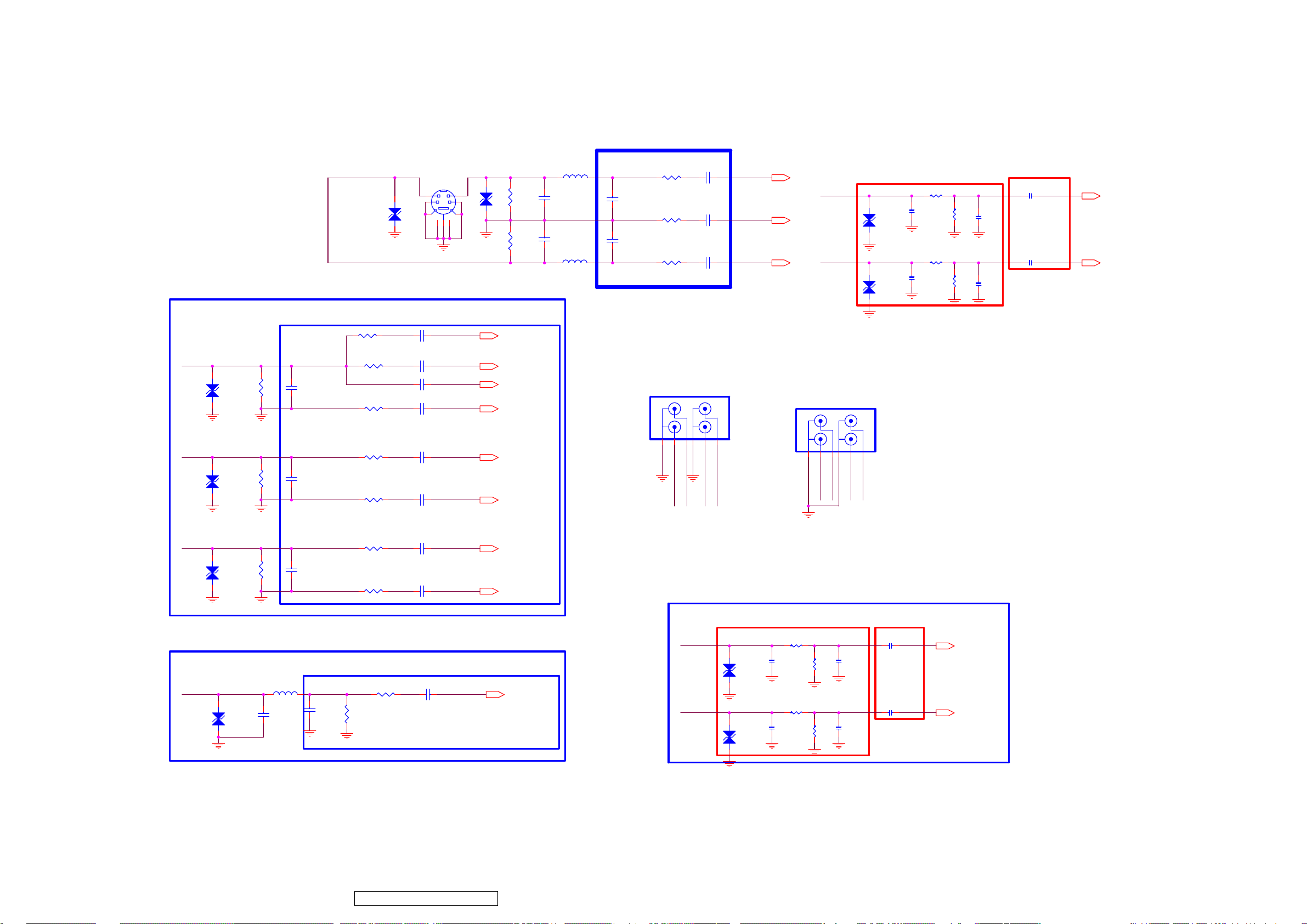
ViewSonic Corporation
72
VT2430-1M
8.8. Video_Interface
YPbPr
Y-IN
Pb-IN
D517
4.7P
D518
4.7P
Y
Pb
R568
75R
R571
75R
Close to MST. IC
C530
NC/10pF
C533
NC/10pF
R566
470R
R567
47R
R569
47R
R570
47R
R572
47R
S-Video Input
P503
MINI DIN4
MINIDIN8
D515
4.7P
6
1
3
C528
1nF
C529
47nF
C553 47nF
C531
47nF
C532
47nF
C534
47nF
8
2
754
9
Near S GNDPIN Side.
RGB0-SOG
RGB0_Y+
Y_CC
RGB0_Y-
RGB0_PB+
RGB0_PB-
D516
4.7P
RGB0-SOG 6
RGB0_Y+ 6
Y_CC 6
RGB0_Y- 6
RGB0_PB+ 6
RGB0_PB- 6
R562
75R
R564
75R
C523
100p
C522
100p
L505
3.3uH 0805
L506
3.3uH 0805
R561 47R
S-LUM0 YIN_0+
C524
100p
C526
100p
R563 47R
R565 47R
S-CHR0 CIN_0+
C521 47nF
C525 47nF
C527 47nF
Near MST.IC Input Side.
YPbPr/Av
Videi In
P504
RCJ-4
453
Pr-IN
Pb-IN
261
Y-IN
CD
AB
CVBS_IN
VCOM1
P505
RCJ-4
RCA Audio Input (ADC IN)
YIN_0+ 6
VCOM1 6
CIN_0+ 6
Close to connector
D521
4.7P
RC_AUL0
D523
4.7P
C543
330pF
C549
330pF
R578
10K
R582
10K
YPbPr/DVI , Av/S
Audio In
CD
AB
261
453
RC_AUR0
RC_AUL0
RC_AUL1
RC_AUR1
R580
12K
R584
12K
Av/S Audio In
Note:Close to MST. IC
C541
1uF/0603
AUR0RC_AUR0
C546
560pF
C547
1uF/0603
AUL0
C552
Keep A_GND trace with Signal.
560pF
Keep Spacing for L/R cahnnel.
Keep trace width(12mil+).
AUR0 6
AUL0 6
Pr-IN
Pr
D519
4.7P
CVBS Input
CVBS_IN
D520
4.7P
R574
75R
L503
3.3uH 0805
C539
680pF
C536
NC/10pF
C540
330pF
R573
47R
R575
47R
C535
47nF
C537
47nF
RGB0_PR+
RGB0_PR-
Close to MST. IC
C538
47nF
CVBS1_IN
R577
75R
R576
47R
RGB0_PR+ 6
RGB0_PR- 6
CVBS1_IN 6
Audio Input
RCA Audio Input (ADC IN)
Close to connector
R579
C544
330pF
C550
330pF
10K
R583
10K
RC_AUR1
D522
4.7P
RC_AUL1
D524
4.7P
R581
12K
R585
12K
YPbPr/DVI
Note:Close to MST. IC
C542
1uF/0603
AUR1
C545
560pF
C548
1uF/0603
AUL1
C551
560pF
AUR1 6
AUL1 6
Confidential - Do Not Copy
Page 76
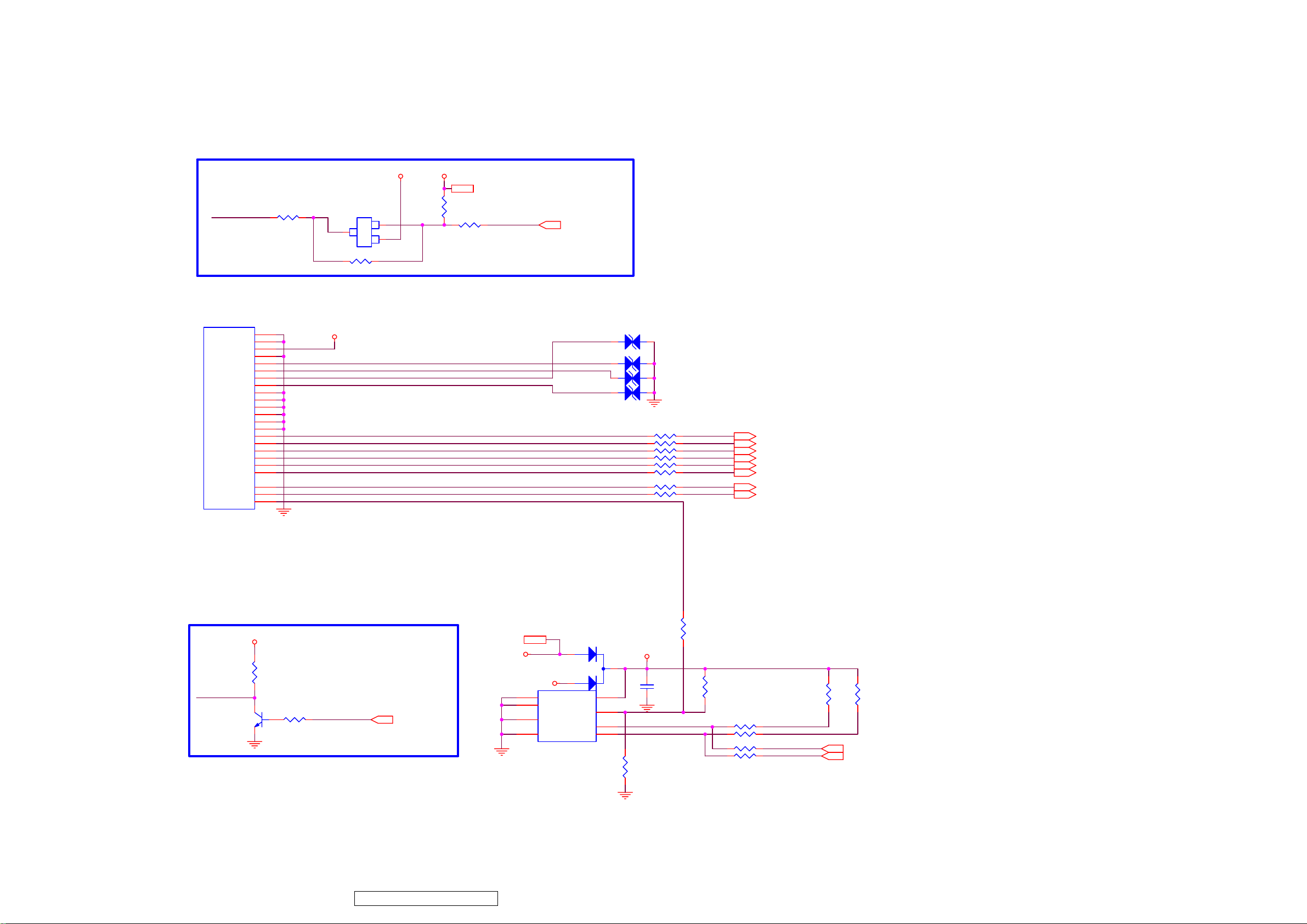
ViewSonic Corporation
73
VT2430-1M
8.9. HDMI Interface
For CEC Leakage Protect
R517
HDMI_CEC
NC/0R
NC/0R
HDMI Connector
P501
HDMI CON
SHIELD
SHIELD
CEC/DDC GND
+5V
DDC SCL
DDC SDA
CEC
HPD
SHIELD
Dat2 shield
Dat1 shield
Dat0 shield
clk shield
SHIELD
DAT0+
DAT0-
DAT1+
DAT1-
DAT2+
DAT2-
clk+
clk-
VCLK
20
21
18
17
15
16
13
19
22
2
5
8
11
23
7
9
4
6
1
3
10
12
14
HDMI-5V
HDMI-5V
HDMI-SCL
HDMI-SDA
HDMI_CEC
HDMI-HPDIN
HDMI_RX0P
HDMI_RX0N
HDMI_RX1N
HDMI_RX2P
HDMI_RX2N
HDMI_CLKP
HDMI_CLKN
3
Q503
NC/2N7002
S
23
D
SOT
G
R519
VCC3.3V-STVCC5V-ST
VCC3.3V-ST 2,6
R516
NC/27K
R518
NC/100R
HDMI-CEC
HDMI-CEC 6
D501
D502 1p
D503 1p
D504 1p
2
1
Update CEC Circuit
NC/4.7P
R520 6R8
R521 6R8
R522 6R8
R523 6R8
R524 6R8
R525 6R8
R526 6R8
R527 6R8
HDMI-RX0P
HDMI-RX0N
HDMI-RX1PHDMI_RX1P
HDMI-RX1N
HDMI-RX2P
HDMI-RX2N
HDMI-CLKP
HDMI-CLKN
HDMI-RX0P 6
HDMI-RX0N 6
HDMI-RX1P 6
HDMI-RX1N 6
HDMI-RX2P 6
HDMI-RX2N 6
HDMI-CLKP 6
HDMI-CLKN 6
Hot-Plug Control
HDMI-5V
R529
1K 0603
HDMI-HPDIN
R533
Q504
MMBT3904
4.7K
1
2 3
HPD_CTRL
HPD_CTRL 6
6,8,10,13,15
VCC5V-ST
VCC5V-ST
DDC EEPROM
D505
BAT54C
HDMI-5V
1
2
3
4 5
I502
NC1
NC2
NC3
GND SDA
VCC
VCLK
SCL
24C22 SMD
8
7
6
HDMI_VCC
C515
100nF
HDMI_SCL
HDMI_SDA
R538
10K
R528
100R
R530
NC
R534 100R
R535 100R
R536100R
R537100R
HDMI-SCL
HDMI-SDA
DDC_SCL
DDC_SDA
R531
10K
DDC_SCL 6
DDC_SDA 6
R532
10K
Confidential - Do Not Copy
Page 77
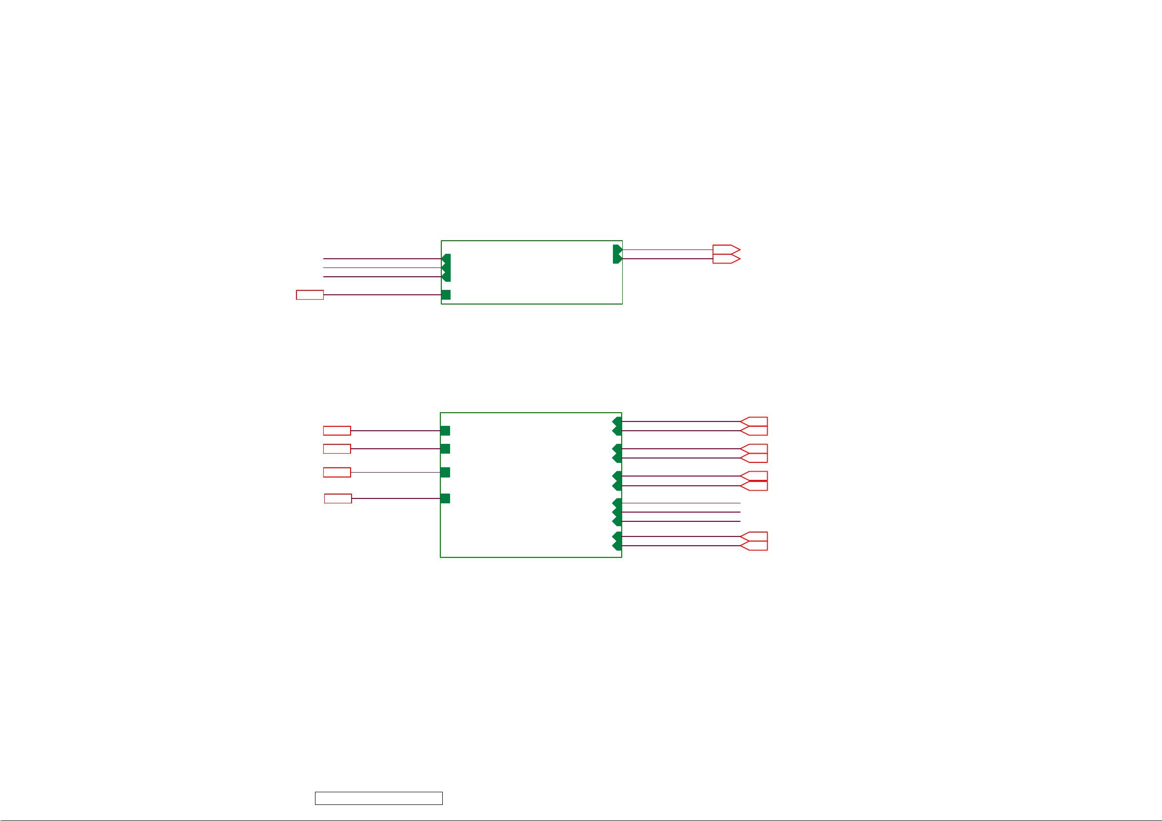
ViewSonic Corporation
74
VT2430-1M
8.10. Audio Block
Audio Interface
PHONE_R
PHONE_L
PHONE_DET
5VAMP2
5VAMP
PHONE_R
PHONE_L
PHONE_DET
5VAMP
12-Audio Interface
PC_Audio-AUL2
PC_Audio-AUR2
PC_Audio-AUL2
PC_Audio-AUR2
PC_Audio-AUL2 6
PC_Audio-AUR2 6
Audio Amp. Interface
5VAMP2
VCC5V-ST2,6,13,15
12V2
VCC3.3V-ST6,13
5VAMP
VCC5V-ST
12V
VCC3.3V-ST
5VAMP
POWER-ON/OFF-GPIO44
12V
POWER-SAVING-GPIO98
VCC3.3V-ST
13-Audio Amp. Interface
AU_DACO_0L
AU_DACO_0R
SHUT_DOWN_AUVCC5V-ST
MUTE_S/GPIO124
PHONE_R
PHONE_L
PHONE_DET
AU_DACO_1L
AU_DACO_1R
AU_DACO_0L
AU_DACO_0R
SHUT_DOWN_AU
POWER-ON/OFF-GPIO44
MUTE_S/GPIO124
POWER-SAVING-GPIO98
PHONE_R
PHONE_L
PHONE_DET
AU_DACO_1L
AU_DACO_1R
AU_DACO_0L 6
AU_DACO_0R 6
SHUT_DOWN_AU 6
POWER-ON/OFF-GPIO44 2.6
MUTE_S/GPIO124 6
POWER-SAVING-GPIO98
AU_DACO_1L 6
AU_DACO_1R 6
6
Confidential - Do Not Copy
Page 78
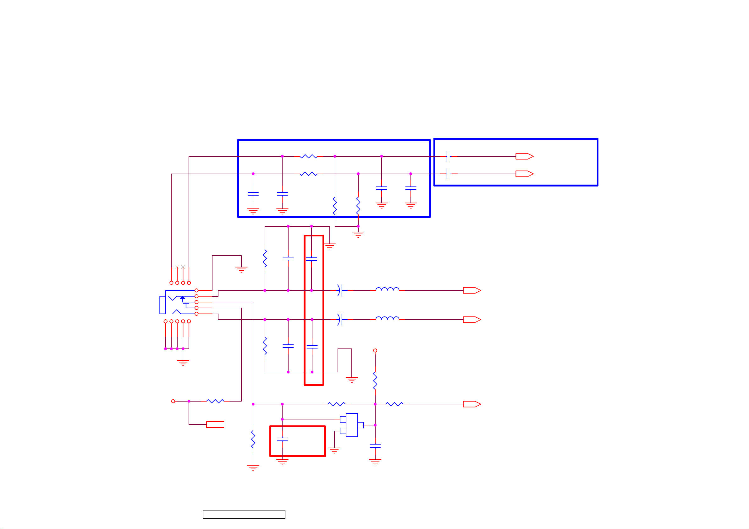
ViewSonic Corporation
75
VT2430-1M
8.11. Audio Interface
Headphone output
PC Audio input
P602
234
101112
14
5
13
Location near phone jack
R650
10K
R729
10K
C645
560pF
0 0603
L611
L601 0 0603
R732
1K
R733
1K
C648
330pF
C649
330pF
C652
330pF
R730
12K
C666
NC
add C666,C665 080910
C650
+
47u/16V
C651
+
47u/16V
C665
NC
R731
12K
5VAMP
C647
330pF
1
9
8
7
6
Close to MST. IC
C643
1uF/0603
C644
1uF/0603
C646
560pF
PHONE_R
PHONE_L
PC_Audio-AUR2
PC_Audio-AUL2
PHONE_R 13
PHONE_L 13
PC_Audio-AUR2 6
PC_Audio-AUL2 6
PHONE JACK NORMAL CLOSE
5VAMP
R735 10K
Confidential - Do Not Copy
R734
10K
R601 0R
1
B
5VAMP 2,13
R659
NC/10K
modify C653 footprint from C0805 to C0603 and add cap 1uF 080910
C653
1uF/0603
SOT
23
2
E
Q606
NC/MMBT3904
C
R736 100R
3
C654
100nF
0: SPEAKER MODE
1: HEADPHONE MODE
PHONE_DET 13
Page 79
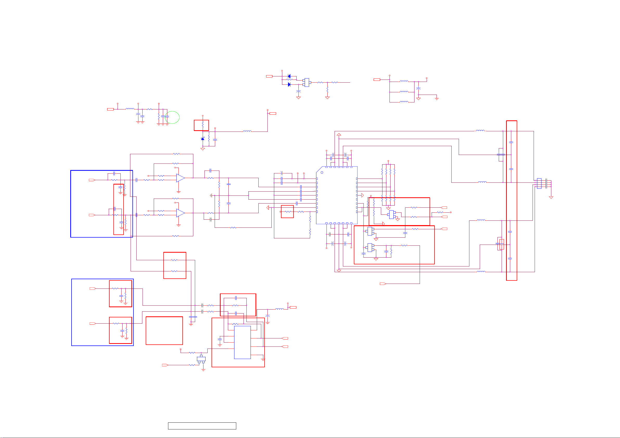
ViewSonic Corporation
76
VT2430-1M
8.12. Audio Amp. Interface
Audio Pre-Amplifier
5VAMPP2,4,5,6
Close to MST. IC
AU_DACO_0L6
6
AU_DACO_0R
Close to MST. IC
AU_DACO_1L6
6
AU_DACO_1R
AU_DACO_0L
AU_DACO_0R
add AU_DACO_1L.R circuit 080910
AU_DACO_1L
AU_DACO_1R
5VAMP
C671 NC/100P
R616 100R
C621
33nF
C672 NC/100P
R634 100R
C628
33nF
C621.C628 from 15nF modify to 33nF 080910
R740 NC/100R
C668
NC/33nF
R738 NC/100R
C667
NC/33nF
VAF AVREF
L605
600R/1.5A L0805
C604
100uF/16V
100nF
C617
AVREF
R617 NC/4.7K
NC/1uF/0603
R621
22K
AVREF
C627
NC/1uF/0603
R635 NC/4.7K
R640
22K
modify earphone balance issue 081014
R741
NC/22K
R739
NC/22K
6
R607
10K
C605
MUTE_S/GPIO124
C606100nF
10K
R609
R615
R618
R633
R636
del R646.R647.Q605. 080910
C607
10uF/0805
R610 NC/82K
VAF
NC/7K5
NC/6.8K
R626 NC/82K
VAF
NC/7K5
NC/6.8K
R697
0R
R742
0R
R743
0R
MUTE_S/GPIO124
PVDD
pull high res(R606) from 5K1 modify to 2K 080901
R696
0R
I603A
84
3
+
1
2
-
NC/LM358/SO8
I603B
84
5
+
7
6
-
NC/LM358/SO8
AUOUTL1A
AUOUTR1A
C640
330pF
5VAMP
R648 10K
MMBT3904
R649
I602 foodprint from "SPDSO08" modify to "SO08" ; C642 cap value from 470n modify to 1uF 080901
D603
Zener/3.3V
AUOUTL0A
AUOUTR0A
Q601
10K
2K2/0603
1uF/0603
C641
330pF
C637
C638
1uF/0603
B
132
R606
R608
100K 0603
1 2
C670 NC/100P
R620
R629 100R
C669 NC/100P
R642 6.8K
R644 6.8K
C
23
SOT
E
AVDD_3.3
AVDD_3.3
C608
1uF/0603
100R
R619
10K
R638
10K
R698 NC/0R
add C663.C664 080910
R643 39K
C642
1uF/0603
L612
NC/600R/1.5A L0805
C622
1nF
C626
1nF
C663 NC/100P
C664 NC/100P
R645 39K
2
IN1
3
BYPASS
6
IN2
5
SHUTDOWN
I602 TPA6113A2
8
VDD
1
VO1
7
VO2
4
GND
12V
C655
AVDD
600R/1.5A 0805
C639
PHONE_R
PHONE_L
D602 NC/1N4148
R602 NC/1K
1 2
D601 NC/1N4148
VCC3.3V-ST 6,13
100uF/16V
100nF
C616
C618 1uF/0603
L610
R632
18K
5VAMP
12V2
VCC3.3V-ST
pull high res(R632) from 0R modify to 18K 080901
100uF/16V
12
C603
NC/330uF/16V
AVDD
C619 1uF/0603
C620 1uF/0603
C623 100nF/0603
C624 1uF/0603
C625 1uF/0603
R661 150K
5VAMP 2,12
PHONE_R 12
PHONE_L 12
AC ON/OFF Mute
Q602
1
B
2
E
NC/MMBT3906
PVDD
R660
R637
SOT
82K
0R
23
3
C
D-5 QFN32
1
2
3
4
5
6
7
8
9
R603 NC/10K
I601
PVDDREG
AVDD
INLP
INLM
VREF
INRM
INRP
AVSS
PLIMIT
C658
R604
R605
NC/10K
PVDD
NC/10u/16V
C656
+
C613 1uF/0805
32
OUTPL2
PVDDPL
OUTPR2
PVDDPR
10
1213141516
11
C631
1uF/0805
NC/10u/16V
+
PVDD
NC/1K
MUTE_N
C657
C601 1uF/0805
293031
PVSSL
OUTPL1
OUTML2
(Product ver)
OUTPR1
PVSSR
OUTMR2
C659
PVDD
NC/10u/16V
+
OUTML1
NCDRC1
NCDRC0
CKOUT
MUTEN
PROTN
SLEEPN
OUTMR1
C632
1uF/0805
NC/10u/16V
+
PVDD
262728
GAIN1
GAIN0
PVDDML
CKIN
PVDDMR
C661
1uF/0603
12V
L604 DUAL BEAD 100R
AVDD_3.3
R613 NC
R612 NC
R624 300K
R623 300K
B
SOT
3
C
23
E
MMBT3904
PHONE_DET
L603
R614 NC
R625 300K
1
2
C660
1uF/0603
R737
22K
L602 NC
NC/22uH/2.9A
R663
R641 47K
12V2
25
24
23
22
AVDD_3.3
21
20
19
18
17
Q603
SOT
3
C
MMBT3904
Q604
SOT
3
C
MMBT3904
PHONE_DET12
R611 10K
R622 NC
R627 47K
R630 10K
Q607
NC/10K
link PROTN and SLEEPN,move R628 and modify R627 from 10K to 47K, R663 from NC to 10K,add Q607 MMT3904 080901
R662
MUTE_N
1
B
23
2
E
add C660.C661.C662(1uF).R737(22K),R641 modify value from 10K to 47K 080910
1
B
C662
23
2
E
1uF/0603
PVDD
C602
+
1000u/16V LSER
SD HI ==>> AMP WORKS
SD LOW==>> SHUT DOWN
HIGH-->STAND BY ENABLE
LOW-->STAND BY
DISABLE
R631
POWER-ON/OFF-GPIO44
R628 10K
POWER-SAVING-GPIO98
SHUT_DOWN_AU
R639
10K
PH_DET
NC
10K
LB
LA
POWER-ON/OFF-GPIO44 6
VCC3.3V-ST
POWER-SAVING-GPIO98
SHUT_DOWN_AU 6
RB
L606 22uH DIP
C609
100nF/0603
C612
C611
0.47u/63V/DIP
C614
100nF/0603
C633
C634
NC/1uF/0805
C629
100nF/0603
C635
100nF/0603
NC/1uF/0805
L607 22uH DIP
6
L608 22uH DIP
RA
0.47u/63V/DIP
L609 22uH DIP
C629,C635,C614,C609 modify package from C0805 to C0603 080910
P601
4
L+
3
L-
2
R-
1
R+
CON4 P=2.5mm
Seaker
6W/8ohm
C610
10nF/0603
C61510nF/0603
C630
10nF/0603
C63610nF/0603
Confidential - Do Not Copy
Page 80
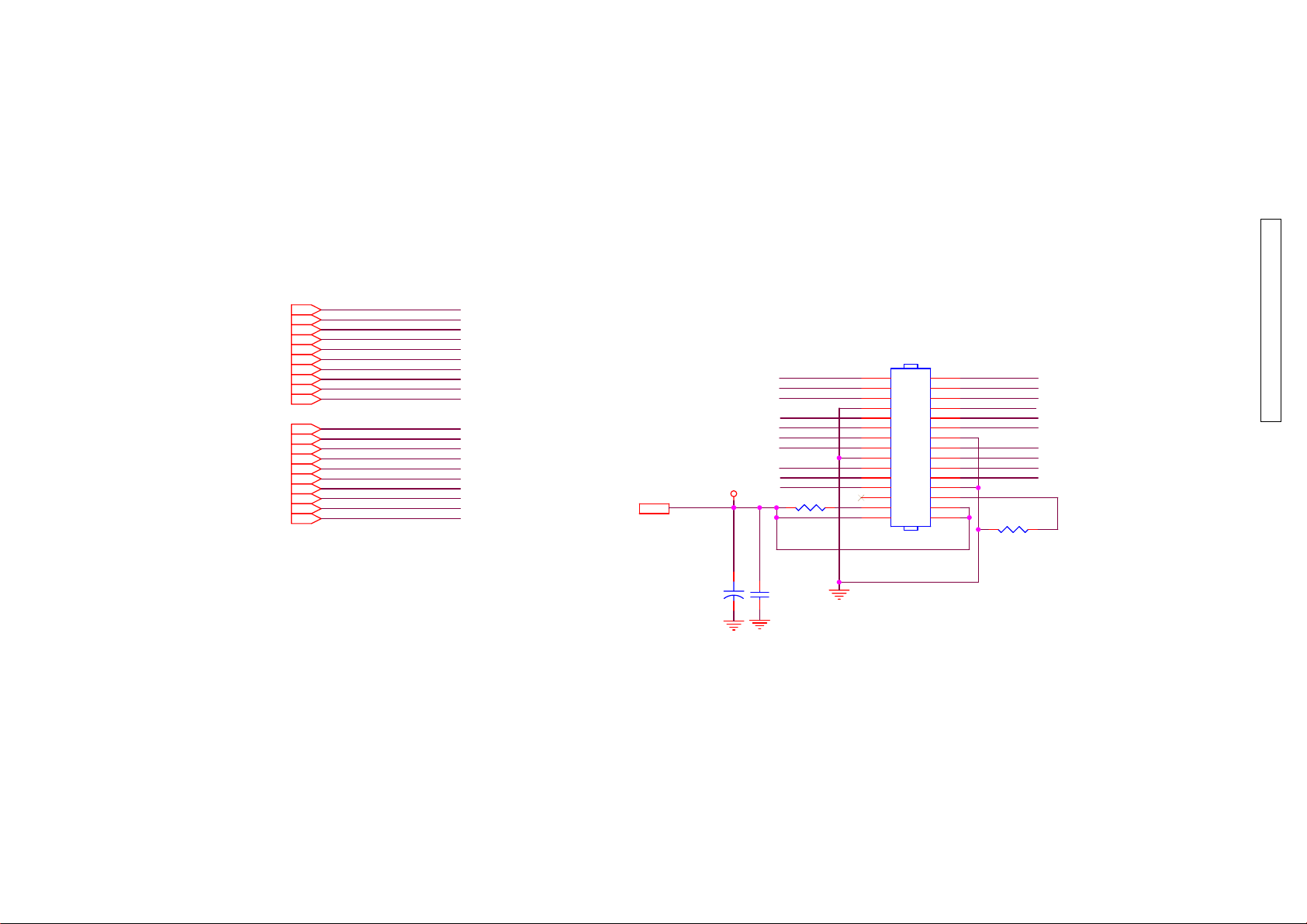
ViewSonic Corporation
VT2430-1M
8.13. LVDSx2 Panel
CMO LVDS PANEL
RXE3+6
RXE3-6
RXEC+6
RXEC-6
RXE2+6
RXE2-6
RXE1+6
RXE1-6
RXE0+6
RXE0-6
RXO3+6
RXO3-6
RXOC+6
RXOC-6
RXO2+6
RXO2-6
RXO1+6
RXO1-6
RXO0+6
RXO0-6
RXE3+
RXE3RXEC+
RXECRXE2+
RXE2RXE1+
RXE1RXE0+
RXE0-
RXO3+
RXO3RXOC+
RXOCRXO2+
RXO2RXO1+
RXO1RXO0+
RXO0-
CMO M260J3-L01:
R695 NC
R699 0R
2
PANEL-VCC
PANEL-VCC
C259
220u/16V LESR
P106
RXO0RXO1-
RXOC+
RXO3+
RXE0+
RXE2+
RXE3+
R699 NC/0
C321
+
100nF
1
3
5
7
9
11
13
15
17
19
21
23
25
27
29
PIN 15x2 2.0mm
2
4
6
8
10
12
14
16
18
20
22
24
26
28
30
RXO0+
RXO1+
RXO2+RXO2RXOCRXO3RXE0-
RXE1+RXE1RXE2RXECRXE3-RXEC+
R695 NC/0
Confidential - Do Not Copy
77
LVDS Panel ( Header Type )
CMO M220J1L01:
R695 0R
R699 0R
AUO M215HW01:
R695 NC
R699 NC
Page 81
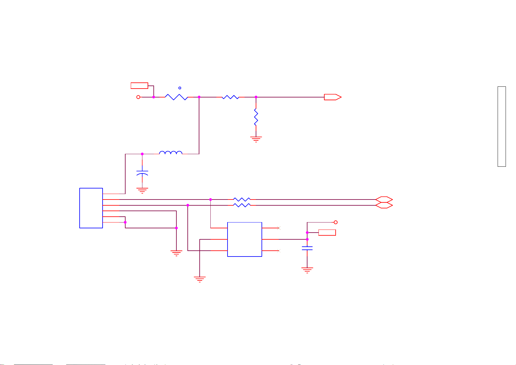
ViewSonic Corporation
VT2430-1M
8.14. USB
P205
NC/USB-A
VBUS
D-
D+
GND
SHELL
SHELL
+5V_General2,3,4,8,10
+5V_General
2.2A
1
2
3
4
5
6
1 2
L209
NC/80R 0805 6A
C317
+
NC/47u/16V
F501
t
NC/5V 0.75A
R314
NC/51K
R362 NC/5.1R
R363
I504
5
GND
6
I/04
USB_OCD_N-GPIO123
R315
NC/100K
NC/5.1R
I/02I/03
VDD
I/01
USB_OCD_N-GPIO123 6
Confidential - Do Not Copy
USB_DM
USB_DP
34
2
1
C318
NC/1nF
VCC5V-ST
VCC5V-ST 6,13,15
USB_DM 6
USB_DP 6
78
NC/AZ1045-04S
Page 82
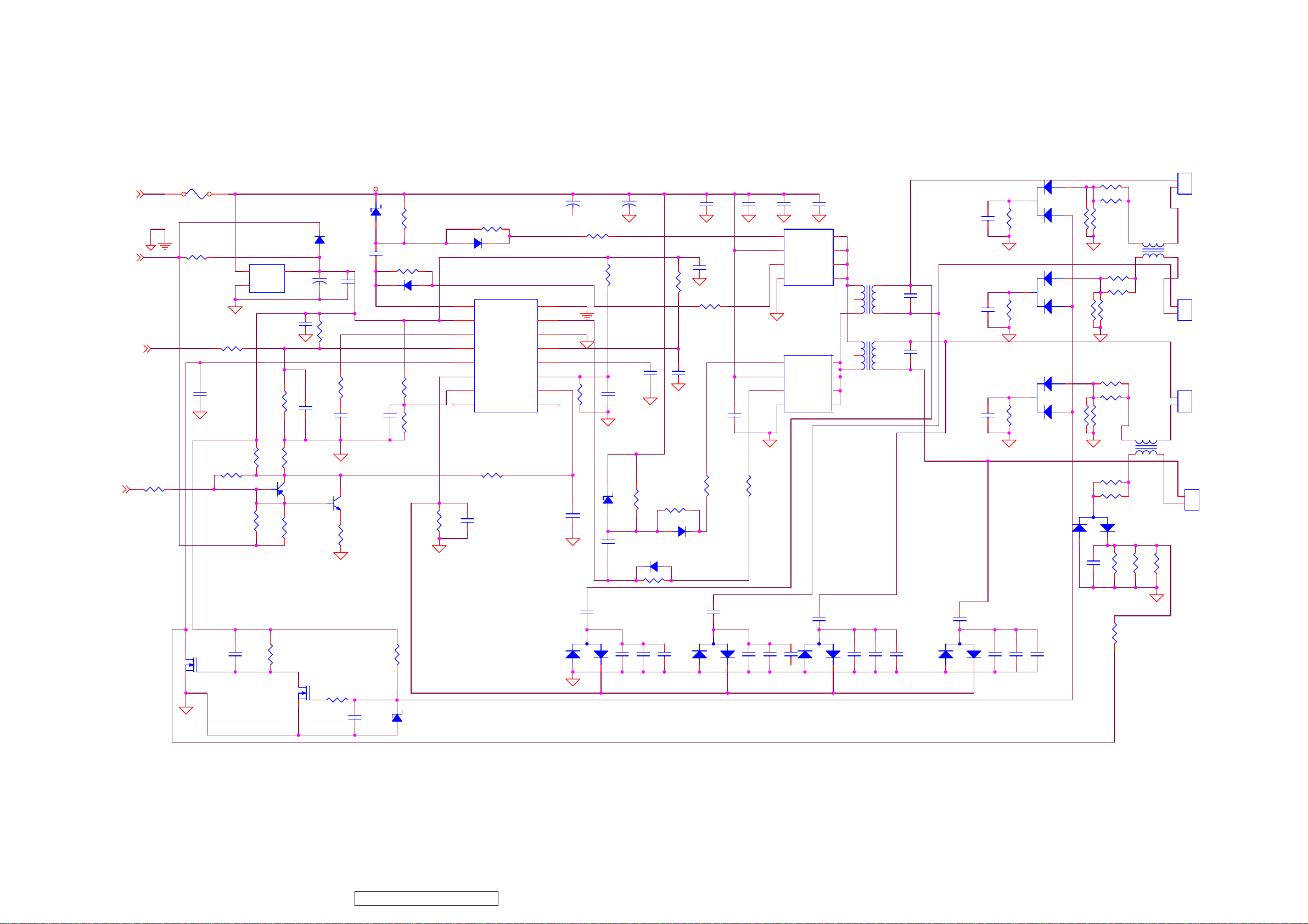
ViewSonic Corporation
79
VT2430-1M
8.15. INVERT
19V
5V
Brightness
ON/OFF
R901 4K7
F901 JP
R906
10
R905 220K
PWM/JP
C929
NC
R923
I902 NC
3 1
IN OUT
2
GND
( option)
TV
R941 10K
0
R902
NC
NC/Option
R907
150K
PWM/NC
1
C903
3
2
D902
NC
C935
47u/16V
R904
47K
Q901
3906
R903
10K
C904
C927
10n
PWM/NC
R942
0
Z902
ZD401 5.6V
C920
C936
NC
R957
PWM/NC
1M
2.2u
+19V REF
47N
R908
10K
C943
1u
2N3904/SOT23
Q901 TV
TV
OPTION
OF
POSITION
Q901
R943
5.1K
R944 100
D906 1N4148
R909
30k
R911
51K
R910
1M
R916 100
D905
1N4148
1
DRV1
2
VDDA
3
TIMER
4 13
DIM CT
5
7 10
8 9
R949 10k
SSTCMP
ISEN
OVPT ENA
NC NC
I901 OZ9938
C905
1000P
PGND
DRV2
GNDA
LCTVSEN
C913
470u/35V
16
15
14
12
116
C908
10n
C912
470u/35V
R920 0
R914
1M
33n/X7R
C944
6.8n/X7R
(33n option)
R915 240K(PWM)
Z903
5.6V
C922
47N
R948
23.2K/1%
C910
R945
5.1K
R946 100
D909 1N4148
C921
0.1u
R921 0
820P/NPO
C911
D908 1N4148
C946
0.1u
C945
1u/0603
C947
0.1u
R919
0
C948
0.1u
R918
0
C932
0.1u
4
G2
3
S
Q905
FW342
2
G1 D
S
1
4
G2
3
S
Q911
2
G1
FW342
1
S
D910BAV70/SOT
R952
C923
104
5
D
6
D
7
C902
5P/3KV/SL
C937
5P/3KV/SL
C933
104
104
C934
8
D
T902
101.2.3
74.5.6
T901
101.2.3
5
D
6
D
7
D
8
D
74.5.6
20K
D911
BAV70/SOT
R967
20K
BAV70/SOT
D912
R973
20K
R972
3K
R927
3K
R963
3K
R939 3K
R960 3K
3K
R971
R953
R962
3K
R969 3K
R970
20K
R974 3K
1 2
3K
R961
3K
R968
3K
1 2
*
CHOKE
R975
3K
D903
BAV99/SOT
L901
CHOKE
L902
P904
1
2
*
34
*
P903
1
2
P902
1
2
34
*
P901
1
2
2N7002/SOT23
Q907
C941
105
Q906
2N7002/SOT23
R976
220K
R977 270
C942
153
R959
330K
Z905
NC
BAV99/SOT
C958
5P/6KV
D915
C957
NC
R947
100
C956
103
R972 NC
R932
10K
R978 374
C959
NC
C955
5P/6KV
D914
BAV99/SOT
C954
NC
C953
NC
C925
103
C950
5P/6KV
BAV99/SOT
D913
C952
NC
C951
103
C960
NC
C940
5P/6KV
D907
BAV99/SOT
C939
NC
C938
103
C961
NC
C919
223
R928 NC
Confidential - Do Not Copy
Page 83
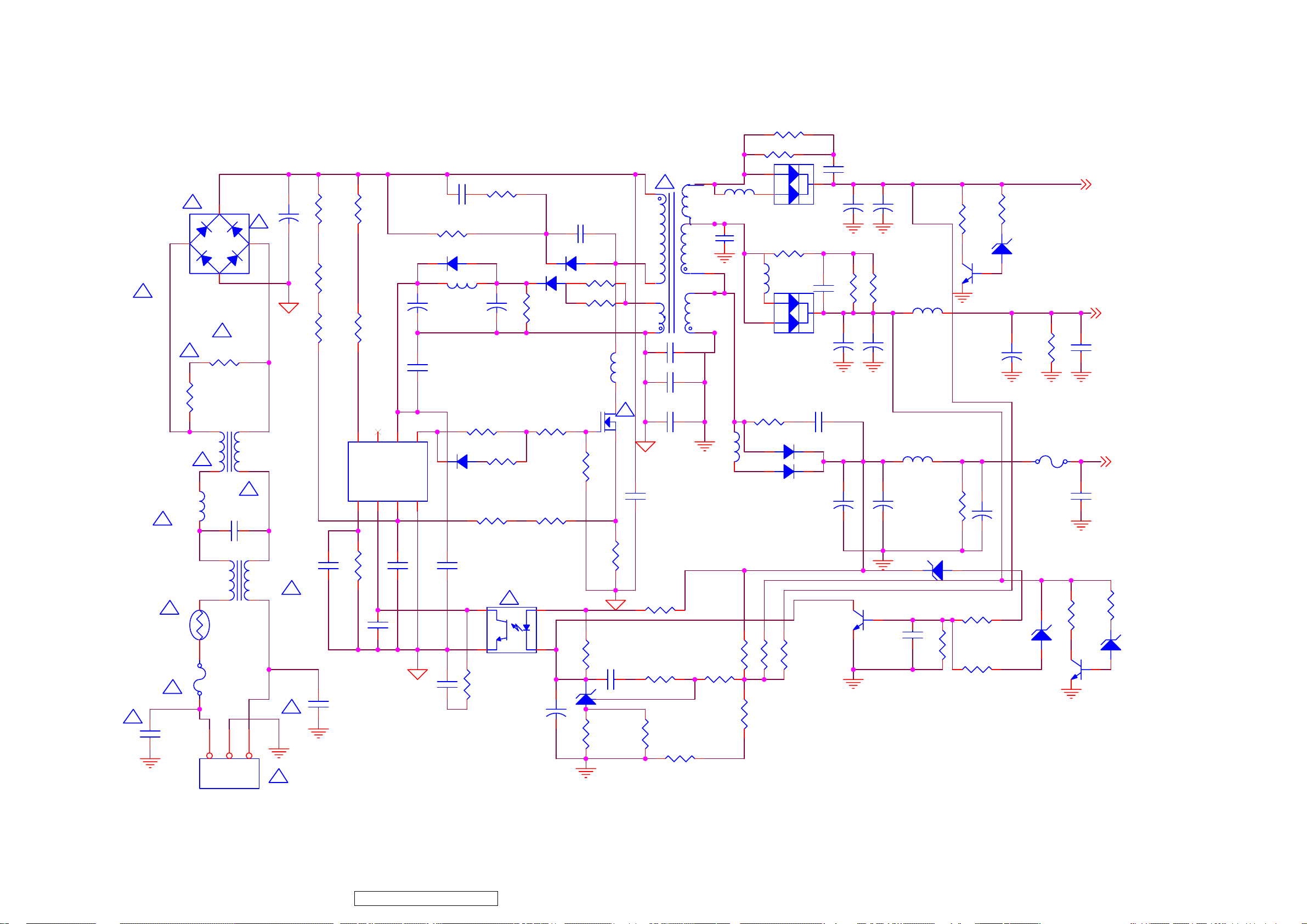
ViewSonic Corporation
80
VT2430-1M
8.16. POWER
C821
NC
R856
NC
R813
option
+
+
C834
NC
+
C860
+
470uF/35V
R815
option
C829
+
1000uF/16V
+
C824
L803
5.2UH
L804 5.2UH
1000UF/16V
Z805
HZ6B2
R850 NC
NC
R840
Q804
2SC945P
C823
+
C825
470uF/16V
R853
NC
Z803
NC
+
470uF/16V
F801
JP
R864NC
5V
19V INV
12V
C836
10n
C835
10n
T801
D801
4KBP06M
!
-+
!
!
!
R812
910K/0805
R803
910K/0805
!
!
J802
!
C801
JUMPER
0.47uF
!
L805
ET-24
+
R839 1M
C805 150uF/400V
R844 1M
R805 1M
I801 LD7576
R806
Jumper
R833
100K 2WS
D824 NC
L806
0.5/3Ts 6x10
+
C810
10UF/50V
R804
Jumper
C814
NC
6
3
Vcc
CS
5
Drv
GND
4
8
7
HV
NC
FB
Adj
2
1
R814 10
C806
1000PF/1KV
C809
NC
R807 10
D825
NC
C807
R846
NC
R817
0R
C828 NC
D806
UF4007
D807
UF4004
+
R810
NC
FERRITE CORE 4.5mm
R857(19)
R832
100R 1/4WS
R855 33
R801 33
Q801
APO9N70
0R
L801
R809
10K
5
6
2
1
C831 2200pF
!
C813
!
C830
680P
C837
NC
NC
L807
14
9
C832NC
13
12
10.11
R859 option
D823
BEAD
GMR10H200C
R820
option
L809
D821 GMR10H125C
R821
NC
L808BEAD
D822 SB1060
D822 SB1060
C859
470uF/35V
C820
option
BEAD
C822
1000uF/16V
C833
1000u/16V
L802
ET20option
!
R802
JP
F801
T2.5AH/250V
!
!
C803
100pF
L
S801
FG
N
!
C802
!
100pF
!
R808 NC
C811 0.047uF
C808 470P
C812 103
C815 NC
103
4
3
R816
NC
10UF/50V
!
I802
TLP621
C827
R811
0.47R 2WS
R823
390
1
R842
2
+
R858
2R2
1K
C826
0.1U
I803
TL431D
R866
2R2
R843
3K
R851
1.1K/1%
R824
3.9K 1%
R827
1K
R825
1.3K 1%
R828
82K 1%
2SC945P
R862
100K
Q803
C815
R865 1K
103
R863
1K 1%
Z802
HZ18A-3
R831
1K
<>
Q802
2SC945P
R837
220R 2WS
R854
470
Z801
HZ12A-3
AC IN 100~240V
Confidential - Do Not Copy
Page 84
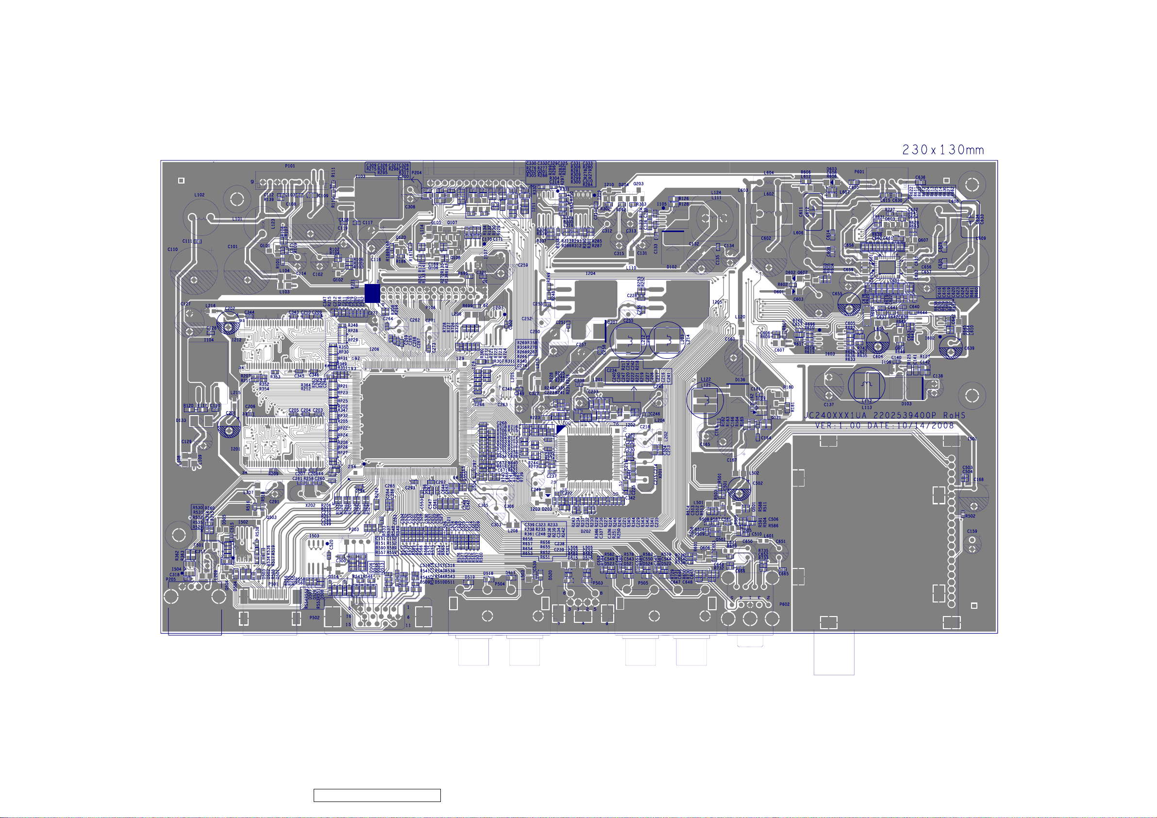
9. PCB Layout Diagrams
ViewSonic Corporation
81
VT2430-1M
9.1. MAIN PCB TOP VIEW
Confidential - Do Not Copy
Page 85
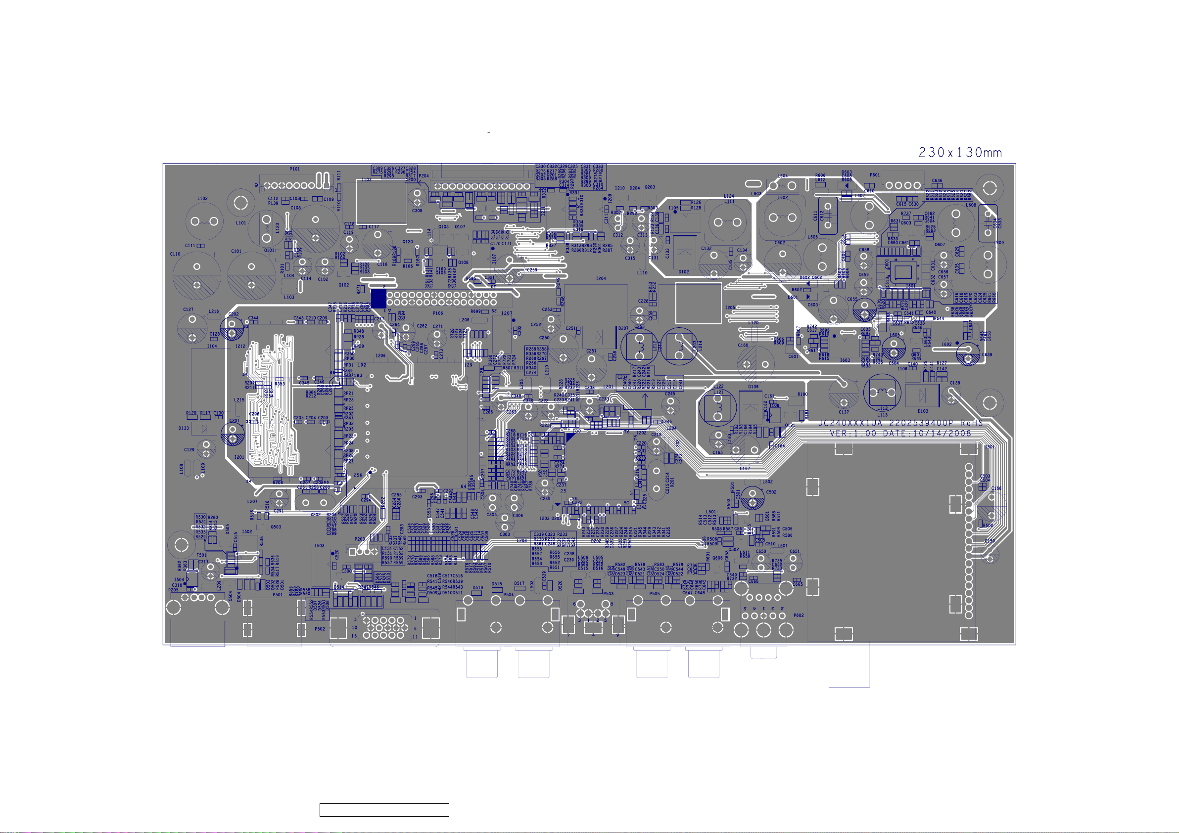
ViewSonic Corporation
82
VT2430-1M
9.2. MAIN PCB BOTTOM VIEW
Confidential - Do Not Copy
Page 86
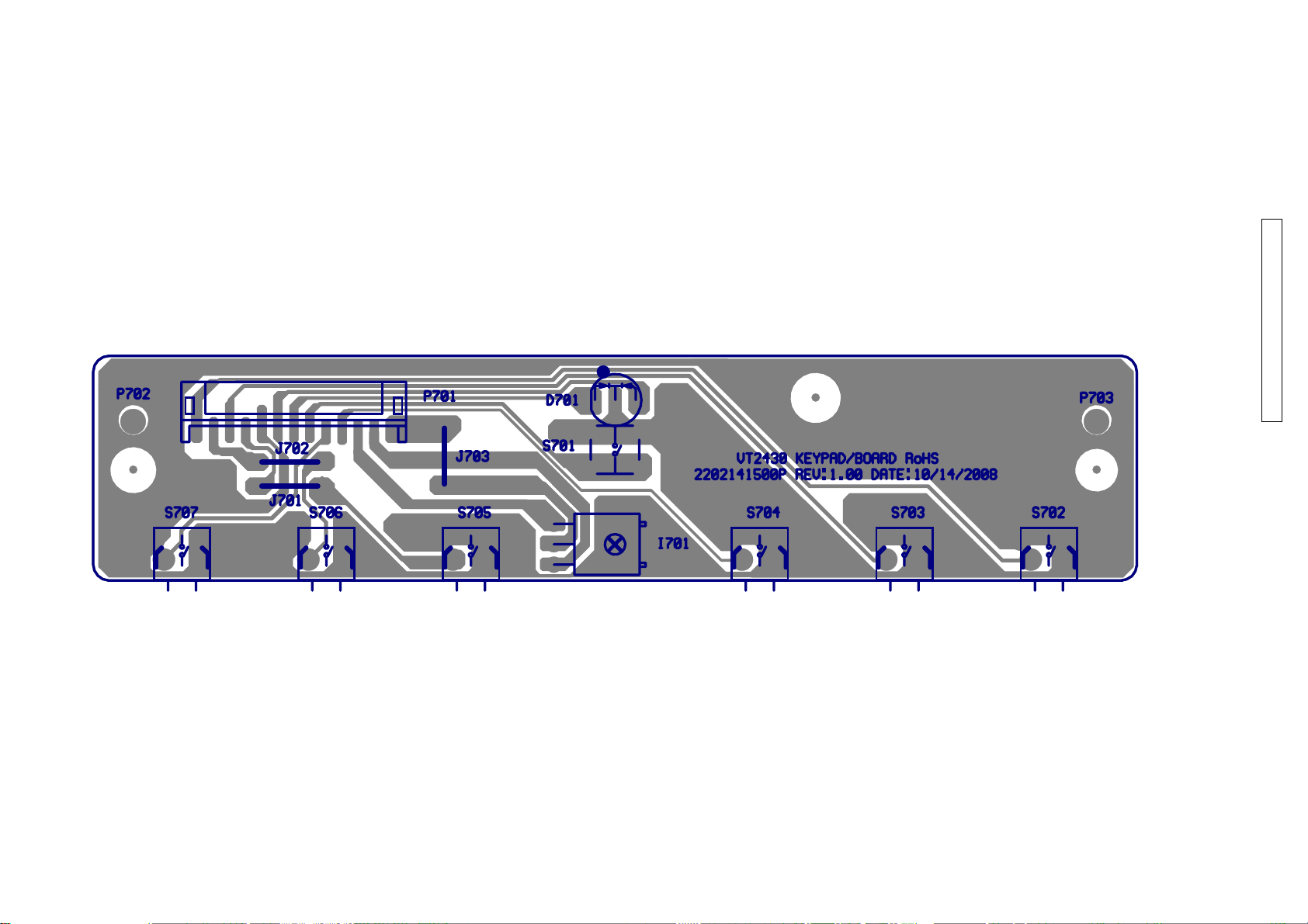
ViewSonic Corporation
VT2430-1M
9.3. CON PCB TOP VIEW
Confidential - Do Not Copy
83
Page 87
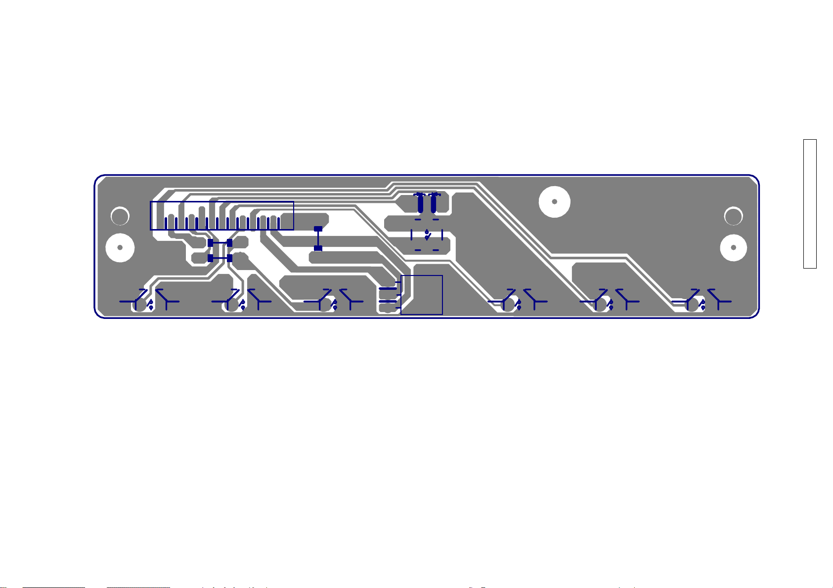
ViewSonic Corporation
VT2430-1M
9.4. CON PCB BOTTOM VIEW
Confidential - Do Not Copy
84
Page 88
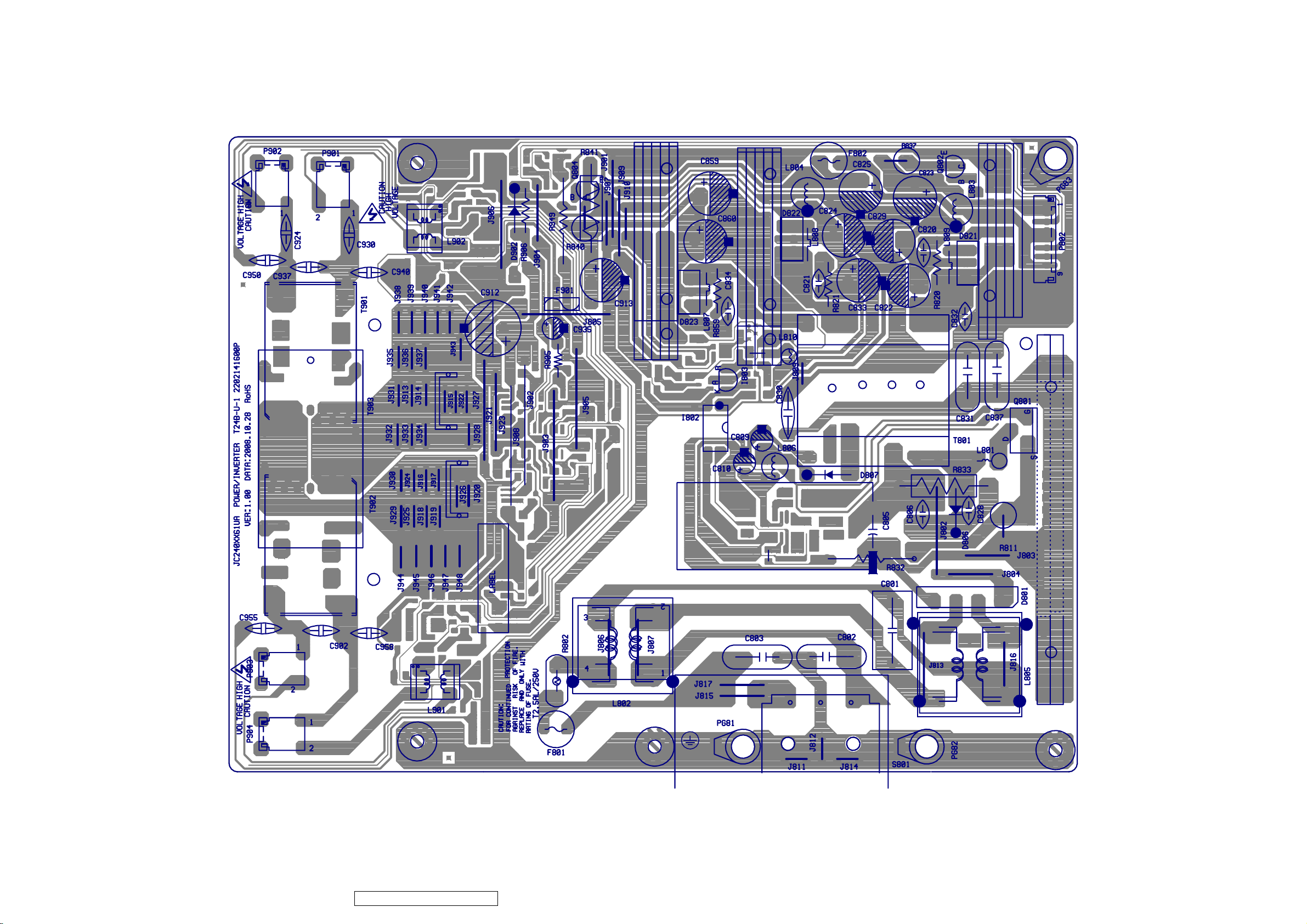
ViewSonic Corporation
85
VT2430-1M
9.5. POWER PCB TOP VIEW
Confidential - Do Not Copy
Page 89
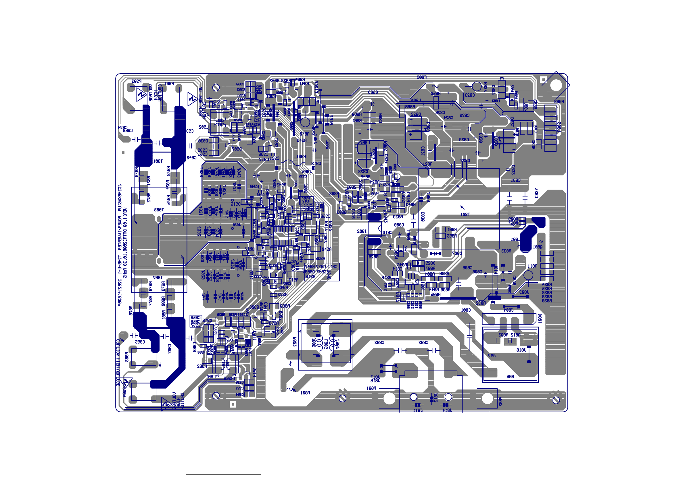
ViewSonic Corporation
86
VT2430-1M
9.6. POWER PCB BOTTOM VIEW
Confidential - Do Not Copy
Page 90
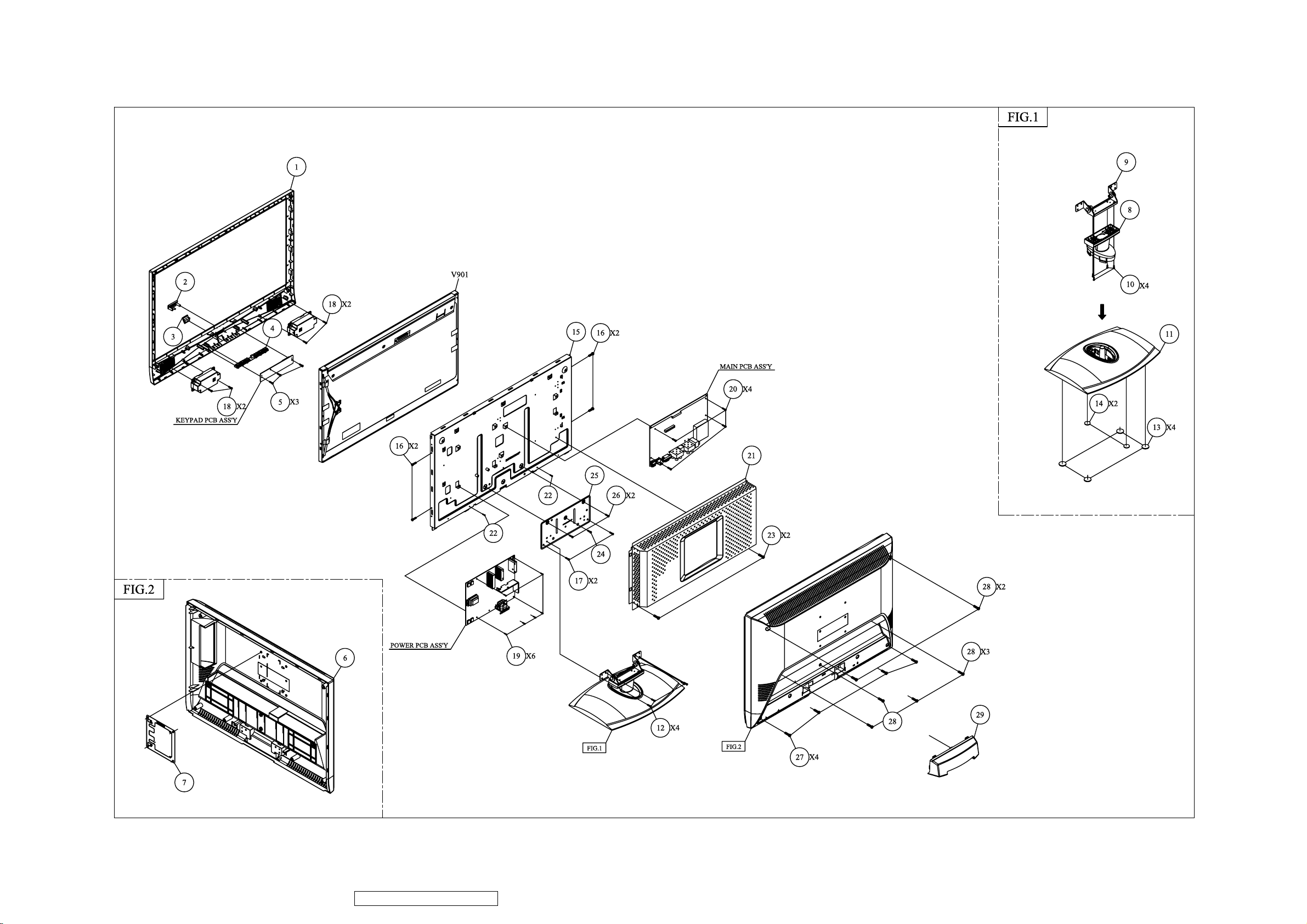
10. Exploded View And Exploded Parts List
ViewSonic Corporation
87
VT2430-1M
Confidential - Do Not Copy
Page 91
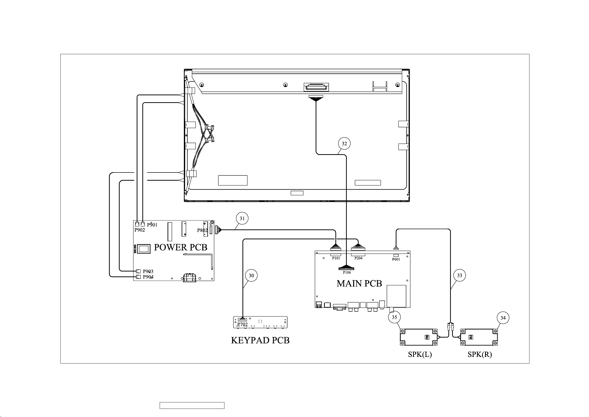
ViewSonic Corporation
88
VT2430-1M
Confidential - Do Not Copy
Page 92
Item
ViewSonic P/N
Ref. P/N
Q'ty1NA
2024285401P
FRONT BEZEL
VT2430 ABS 94HB G.L BLACK C
1
2NA2053760201P
LED INDIC.-PWR
N2430P UT0520T COLOR T57015
1
3NA2033154000P
IR COVER
N2430P PC GE-121R-21051
1
4NA2044275301P
FUNCTION KEY
N2430P ABS 94HB BLACK C
1
5
M-SCW-0824-0285
2084730082P
SCREW BND T+
M3X8(BND T+)
3
6NA2022281301P
CABI BACK
VT2430 ABS 94HB BLACK C USA
1
7
HW-00003031
2071872900P
BRACKET FIX
JT198QP SECC 0.8T WALL MOUNT
1
8NA2028560601P
NECK
N2430P ABS 94HB BLACK C
1
9NA2106664700P
HINGE
N2430P SECC T=2.0°~20° 50KG-CM
1
10
HW-00008139
2086240102P
SCREW P SW+
M4*10 PSW+ ZN
4
11NA2028268101P
STAND
VT2430 ABS 94HB G.L BLACK C
1
12NA2082640102P
SCREW
M4X10 P=0.7
4
13NA2039820601P
FOOT PAD
f20*2.5T SQUARE GRAIN BLK
4
14NA2039820200P
FOOT PAD
f10*2T SQUARE GRAIN BLK
2
15NA2071990600P
METAL FITTG
N2430P PANEL SECC T=0.8 USA
1
16NA2083630069P
SCREW FMS+
M3*6,M,S-TITE,F,ZN
4
17
M-SCW-0824-0285
2084730082P
SCREW BND T+
M3X8(BND T+)
2
18
M-SCW-0824-0123
2084740102P
SCREW BND T+
M4X10(BND T+)
4
19
M-SCW-0824-0811
2080003700P
SCREW SPE
ISZZTER001A M3*6L MSWR17/FZMYI
6
20
M-SCW-0824-0811
2080003700P
SCREW SPE
ISZZTER001A M3*6L MSWR17/FZMYI
4
21NA2071684000P
SHIELD PLATE
N2430P SPTE T=0.3MM USA
1
22
M-SCW-0824-0811
2080003700P
SCREW SPE
ISZZTER001A M3*6L MSWR17/FZMYI
2
23
M-SCW-0824-0285
2084730082P
SCREW BND T+
M3X8(BND T+)
2
24
M-SCW-0824-6719
2082630062P
SCREW
M3X6 P=0.5
1
25NA2071895900P
BRACKET FIX
N2430P FOR HING T=1.2MM
1
26
M-SCW-0824-6719
2082630062P
SCREW
M3X6 P=0.5
2
27NA2084740104P
SCREW BND T+
M4X10(BND T+) (BLK)
4
28NA2082630064P
SCREW
M3*6 P=0.5 BLACK
6
29NA2027273901P
DUST COVER
N2430P ABS 94HB BLACK C
1
30
CB-00008888
2427413021P
WIRE HARNESS
13/13P H/H 1007#26 L=400mm
1
31
CB-00008889
2427409020P
WIRE HARNESS
9/9P H/H 1007#24 L=150mm
1
32
CB-00008890
2427430071P
WIRE HARNESS
30/30P H/H 1792#32 L=130mm
1
33
CB-00008891
2427404070P
WIRE HARNESS
4/2+2P H/A 1007#24 L=490mm
1
34NA2391306003P-01
SPEAKER ASS'Y(RA)
6W/8ohm (L) L90*W34*H28mm DONGLI (X09040PM05-52-B)
1
34NA2391306003P-02
SPEAKER ASS'Y(RB)
6W/8ohm (L) L90*W34*H28mm YUNGTECH
1
35NA2391306004P-01
SPEAKER ASS'Y(RA)
6W/8ohm (R) L90*W34*H28mm DONGLI (X09040PM05-51-B)
1
35NA2391306004P-02
SPEAKER ASS'Y(RB)
6W/8ohm (R) L90*W34*H28mm YUNGTECH
1
Description
Exploded Parts List ( VT2430-1M )
ViewSonic Corporation
89
VT2430-1M
ViewSonic Model Number: VS12335-1M
Rev: 1a
Confidential - Do Not Copy
Page 93
Item
Description
Part Name
Description
ECR/ECN
ViewSonic P/N
Ref. P/N
Location
Universal number#
B-00009345
6201-7024166111
201
B-00009346
6202-7024166111
202
B-00009347
6204-7024166111
204
Guide, CD Rom; Label]
Control;Power Cord]
ViewSonic Corporation
90
VT2430-1M
11. Recommended Spare Parts List
ViewSonic Model Number: VS12335-1M
Serial No. Prefix: R4S
Rev: 1a
1 AC POWER CORD USA WALL 1.83M BLACK A-00005362 2427130046P P951
Accessories: [Adapter, Remote
2 REMOTE CONTROL ViewSonic NX1932W & NX2232W ATSC A-00008204 2419200161P H901
3 PCB ASS'Y BLOCK (MAIN)
PC Board Assembly: [All
4 PCB ASS'Y BLOCK (CON)
PCBA]
5 PCB ASS'Y BLOCK (POWER)
6 BEZEL ASS'Y N2430P ABS 94HB BLACK C C-00009216 2603308974
Cabinets: [Front Panel, All
7 CABI BACK ASSY N2430P ABS 94HB BLACK C C-00009217 2603408173
Covers, Base Assembly]
8 STAND ASSY VT2430 ABS 94HB G.L BLACK C C-00009218 2603207447
9 WIRE HARNESS 13/13P H/H 1007#26 L=400mm CB-00008888 2427413021P P703
Cables: [All Cables]
10 WIRE HARNESS 9/9P H/H 1007#24 L=150mm CB-00008889 2427409020P P812
11 WIRE HARNESS 30/30P H/H 1792#32 L=130mm CB-00008890 2427430071P P981
12 WIRE HARNESS 4/2+2P H/A 1007#24 L=490mm CB-00008891 2427404070P P988
Documentation: [Quick Start
13
Electronic Components: [CRT-
EEPROM, Fly Back
Transformer, Microprocessor]
[LCD TV-Panel]
14
15 CARTON BOX VIEWSONIC VT2430-1M VS12335-1M P-00009322 2011124001P 6P01
Packing Material: [Box, Foam,
16 POLYFOAM N2430P (R) EPS P-00009323 2012114500P 6P20
Bags]
17 POLYFOAM N2430P(L) EPS P-00009324 2012114600P 6P21
OWNER GUIDE ASSY N2430P-1M WIZARD VS12335-1M CMO DC-00009276 2604208133
LCD PANEL M236H1-L01 (A) CMO (2/5/5 , ND 8%) E-00009190 2212018900P V901
Above listed items are examples, supplier can expand the rows to add more necessary items.
Remark 1:
Remark 2:
All revised RSPLs with newly added items or any change made should be highlighted and correlated with the ECN/ECR approved by ViewSonic Corporation. This is to
eliminate repeated cross checks of each item between this version and prior versions.
RECOMMENDED SPARE PARTS LIST (VT2430-1M)
Confidential - Do Not Copy
Page 94
Item
ViewSonic P/N
Ref. P/N
Location
Universal number#
Q'ty
1
B-00009346
6202-7024166111
PCB ASS'Y BLOCK (CON)
12B-00009347
6204-7024166111
PCB ASS'Y BLOCK (POWER)
13NA
2434420400P
AL SHIELDING TAPE
W40*L40 AL
14CB-00008888
2427413021P
WIRE HARNESS
13/13P H/H 1007#26 L=400mm
15CB-00008889
2427409020P
WIRE HARNESS
9/9P H/H 1007#24 L=150mm
16CB-00008890
2427430071P
WIRE HARNESS
30/30P H/H 1792#32 L=130mm
17CB-00008891
2427404070P
WIRE HARNESS
4/2+2P H/A 1007#24 L=490mm
18E-00009190
2212018900P
LCD PANEL
M236H1-L01 (A) CMO (2/5/5 , ND 8%)
19NA
2391306003P-01
SPEAKER ASS'Y
6W/8ohm (L) L90*W34*H28mm DONGLI (X09040PM05-54-B)
110NA
2391306003P-02
SPEAKER ASS'Y
6W/8ohm (L) L90*W34*H28mm YUNGTECH
111NA
2391306004P-01
SPEAKER ASS'Y
6W/8ohm (R) L90*W34*H28mm DONGLI (X09040PM05-53-B)
112NA
2391306004P-02
SPEAKER ASS'Y
6W/8ohm (R) L90*W34*H28mm YUNGTECH
113M-SCW-0824-0285
2084730082P
SCREW BND T+
M3X8(BND T+)
414M-SCW-0824-0285
2084730082P
SCREW BND T+
M3X8(BND T+)
315NA
2504100800P
PLASTIC TAPE
PL-CELLONO.60
160016NA
2504500200P
FASTENING TAPE
MASKING TAPE,18M/M (WIDTH)
56717NA
2504200700P
ADHESI TAPE
3M 1350(b) 25*80
42018NA
2504100900P
PLASTIC TAPE
PL-CELLONO.75
24519C-00009216
2603308974
BEZEL ASS'Y
N2430P ABS 94HB BLACK C
120NA
2071990600P
METAL FITTG
N2430P PANEL SECC T=0.8 USA
121NA
2083630069P
SCREW FMS+
M3*6,M,S-TITE,F,ZN
422M-SCW-0824-0285
2084730082P
SCREW BND T+
M3X8(BND T+)
223M-SCW-0824-0123
2084740102P
SCREW BND T+
M4X10(BND T+)
424M-SCW-0824-0811
2080003700P
SCREW SPE
ISZZTER001A M3*6L MSWR17/FZMYI
625M-SCW-0824-0811
2080003700P
SCREW SPE
ISZZTER001A M3*6L MSWR17/FZMYI
426NA
2071684000P
SHIELD PLATE
N2430P SPTE T=0.3MM USA
127M-SCW-0824-0811
2080003700P
SCREW SPE
ISZZTER001A M3*6L MSWR17/FZMYI
228M-SCW-0824-0285
2084730082P
SCREW BND T+
M3X8(BND T+)
229M-SCW-0824-6945
2080004000P
SCREW SPE
STAND-OFF HEX #4-40UNC H5*5*7L
230M-SCW-0824-6719
2082630062P
SCREW
M3X6 P=0.5
131NA
2071895900P
BRACKET FIX
N2430P FOR HING T=1.2MM
132M-SCW-0824-6719
2082630062P
SCREW
M3X6 P=0.5
233NA
2072467100P
INSULATOR
L110*W55*T0.5 mm
134A-00008204
2419200161P
REMOTE CONTROL
ViewSonic NX1932W & NX2232W ATSC
135A-00005362
2427130046P
AC POWER CORD
USA WALL 1.83M BLACK
136C-00009218
2603207447
STAND ASSY
VT2430 ABS 94HB G.L BLACK C
137C-00009217
2603408173
CABI BACK ASSY
N2430P ABS 94HB BLACK C
138NA
2603807190
NECK ASSY
N2430P ABS 94HB BLACK C
139DC-00009276
2604208133
OWNER GUIDE ASSY
N2430P-1M WIZARD VS12335-1M CMO
140HW-00008139
2086240102P
SCREW P SW+
M4*10 PSW+ ZN
441NA
2084740104P
SCREW BND T+
M4X10(BND T+) (BLK)
442NA
2082630064P
SCREW
M3*6 P=0.5 BLACK
643NA
2027273901P
DUST COVER
N2430P ABS 94HB BLACK C
144P-00009322
2011124001P
CARTON BOX
VIEWSONIC VT2430-1M VS12335-1M
145NA
2055632329P
LABEL
VT2430-1M VS12335-1M (M) CMO USA
146NA
2055636109P
LABEL
VT2430-1M VS12335-1M SMALL LABEL
147M-LB-0813-0856
2055613379P
LABEL
VIEWSONIC CONTAINER LABEL
0.0248M-LB-0813-0530
2055617101P
LABEL
10*20 HI-POT TESTED OK
149M-LB-0813-0959
2055613392P
LABEL
VSC HIGH VOLTAGE WARNING LABEL
150P-00009323
2012114500P
POLYFOAM
N2430P (R) EPS
151P-00009324
2012114600P
POLYFOAM
N2430P(L) EPS
152NA
2055135492P
LABEL
VT2430 -1M VS12335-1M CMO USA
153P-00008950
2013054065P
POLYETHY BAG
800x800mm EPE/T=0.5mm+HDPE/T=0.02mm 26"
154P-00008935
2011100130P
CARTON BOX
1125*1125*8 (MM)
0.02
ViewSonic Model Number: VS12335-1M
ViewSonic Corporation
91
VT2430-1M
Rev: 1a
BOM LIST ( VT2430-1M )
Description
Confidential - Do Not Copy
Page 95
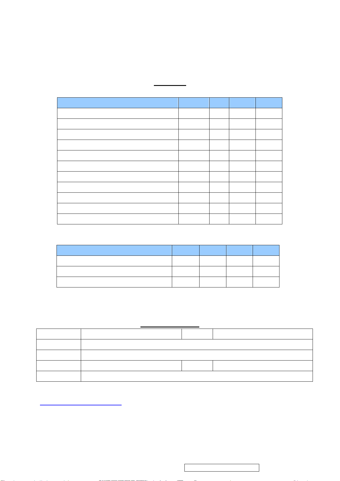
* Reader’s Response*
ViewSonic Corporation
92
VT2430-1M
Dear Readers:
Thank you in advance for your feedback on our Service Manual, which allows continuous improvement
of our products. We would appreciate your completion of the Assessment Matrix below, for return to
ViewSonic Corporation.
Assessment
A. What do you think about the content of this Service Manual?
Unit Excellent Good Fair Bad
1. Precautions and Safety Notices
2. Specification
3. Front Panel Function Control Description
4. Circuit Description
5. Adjusting Procedure
6. Trouble Shooting Flow Chart
7. Block Diagram
8. Schematic Diagrams
9. PCB Layout Diagrams
10. Exploded View And Exploded Parts List
11. Recommended Spare Parts List
B. Are you satisfied with this Service Manual?
Item Excellent Good Fair Bad
1. Service Manual Content
2. Service Manual Layout
3. The form and listing
C. Do you have any other opinions or suggestions regarding this service manual?
Reader’s basic dada:
Name: Title:
Company:
Add:
Tel: Fax:
E-mail:
After completing this form, please return it to ViewSonic Quality Assurance in the USA at facsimile
1-909-839-7943. You may also e-mail any suggestions to the Director, Quality Systems & Processes
([email protected]
)
Confidential - Do Not Copy
 Loading...