

Page 1

PJ-vTouch-50s
Projector Interactive Kits
User Guide
Model No. VS16953
IMPORTANT: Please read this User Guide to obtain important information on installing
and using your product in a safe manner, as well as registering your product for future
service. Warranty information contained in this User Guide will describe your limited
coverage from ViewSonic Corporation, which is also found on our web site at http://
www.viewsonic.com in English, or in specic languages using the Regional selection
box in the upper right corner of our website. “Antes de operar su equipo lea cu
idadosamente las instrucciones en este manual”
Page 2

Thank you for choosing ViewSonic
As a world leading provider of visual solutions, ViewSonic is dedicated to
exceeding the world’s expectations for technological evolution, innovation,
and simplicity. At ViewSonic, we believe that our products have the
potential to make a positive impact in the world, and we are confident that
the ViewSonic product you have chosen will serve you well.
Once again, thank you for choosing ViewSonic !
Page 3

i
Compliance Information
Please read before proceeding
• Use only the batteries and power adapter provided by the manufacturer. The use
of unauthorized accessories may void your warranty.
• Do not store your device in temperatures higher than 50°C (122°F).
• The operating temperature for this device is from 0°C (32°F) to 35°C (95°F).
FCC Notice
The following statement applies to all products that have received FCC approval.
Applicable products bear the FCC logo, and/or an FCC ID in the format FCC ID:
GSS-VS15180 on the product label.This device complies with part 15 of the FCC
Rules. Operation is subject to the following two conditions: (1) This device may
not cause harmful interference, and (2) This device must accept any interference
received, including interference that may cause undesired operation. This
mobiledevice has been tested and found to comply with the limits for a Class B
digital device, pursuant to Part 15 of the FCC Rules. These limits are designed
to provide reasonable protection against harmful interference in a residential
installation. This equipment generates, uses and can radiate radio frequencyenergy
and, if not installed and used in accordance with the instructions, may cause
harmful interferenceto radio communications. However, there is no guarantee that
interference will not occur in a particular installation. If this equipment does cause
harmful interference to radio or television reception, which can be determined
by turning the equipment off and on, the user is encouraged to try to correct the
interference by one or more of the following measures
• Reorient or relocate the receiving antenna.
• Increase the separation between the equipment and receiver.
• Connect the equipment into an outlet on a circuit different from that to which the
receiver is connected.
• Consult the dealer or an experienced radio/TV technician for help.
Changes or modifications not expressly approved by the party responsible for
compliance could void theuser’s authority to operate the equipment.The antenna(s)
used for this transmitter must not be colocated or operating in conjunction with any
otherantenna or transmitter.
The device was tested and complies to measurement standards and procedures
specified in FCC OET Bulletin 65, Supplement C
Page 4

ii
FCC SAR Information
This equipment complies with FCC radiation exposure limits set forth for an
uncontrolled environment. End users must follow the specific operating instructions
for satisfying RF exposure compliance.
This transmitter must not be co-located or operating in conjunction with any other
antenna or transmitter. This equipment should be installed and operated with a
minimum distance of 20 centimeters between the radiator and your body.
The users manual or instruction manual for an intentional or unintentional radiator
shall caution the user that changes or modifications not expressly approved by
the party responsible for compliance could void the user's authority to operate the
equipment.
CE Conformity for European Countries
The device complies with the EMC Directive 2014/30/EU and Low Voltage
Directive 2014/35/EU, R&TTE Directive 1999/5/EC.
Following information is only for EU-member states:
The mark shown to the right is in compliance with the Waste Electrical and
Electronic Equipment Directive 2012/19/EU (WEEE).
The mark indicates the requirement NOT to dispose the equipment as
unsorted municipal waste, but use the return and collection systems
according to local law.
If the batteries, accumulators and button cells included with this equipment,
display the chemical symbol Hg, Cd, or Pb, then it means that the battery has
a heavy metal content of more than 0.0005% Mercury, or more than 0.002%
Cadmium, or more than 0.004% Lead.
European Union Regulatory Conformance
The equipment complies with the RF Exposure Requirement 1999/519/EC, Council
Recommendation of 12 July 1999 on the limitation of exposure of the general
public to electromagnetic fields (0-300 GHz). This equipment meets the following
conformance standards: EN301489-1, EN301489-17, EN55032/24, EN60950-1,
EN300328, EN301893.
We, hereby, declare that this Wi-Fi radio is in compliance with the essential
requirements and other relevant provisions of Directive 1999/5/EC.
Page 5

iii
Declaration of RoHS2 Compliance
This product has been designed and manufactured in compliance with Directive
2011/65/EU of the European Parliament and the Council on restriction of the use
of certain hazardous substances in electrical and electronic equipment (RoHS2
Directive) and is deemed to comply with the maximum concentration values issued
by the European Technical Adaptation Committee (TAC) as shown below:
Substance
Proposed Maximum
Concentration
Actual Concentration
Lead (Pb) 0.1% < 0.1%
Mercury (Hg) 0.1% < 0.1%
Cadmium (Cd) 0.01% < 0.01%
Hexavalent Chromium (Cr6+) 0.1% < 0.1%
Polybrominated biphenyls (PBB) 0.1% < 0.1%
Polybrominated diphenyl ethers (PBDE) 0.1% < 0.1%
Certain components of products as stated above are exempted under the Annex III
of the RoHS2 Directives as noted below:
Examples of exempted components are:
1. Mercury in cold cathode fluorescent lamps and external electrode fluorescent
lamps (CCFL and EEFL) for special purposes not exceeding (per lamp):
(1) Short length (≦500 mm): maximum 3.5 mg per lamp.
(2) Medium length (>500 mm and ≦1,500 mm): maximum 5 mg per lamp.
(3) Long length (>1,500 mm): maximum 13 mg per lamp.
2. Lead in glass of cathode ray tubes.
3. Lead in glass of fluorescent tubes not exceeding 0.2% by weight.
4. Lead as an alloying element in aluminium containing up to 0.4% lead by weight.
5. Copper alloy containing up to 4% lead by weight.
6. Lead in high melting temperature type solders (i.e. lead-based alloys containing
85% by weight or more lead).
7. Electrical and electronic components containing lead in a glass or ceramic other
than dielectric ceramic in capacitors, e.g. piezoelectronic devices, or in a glass or
ceramic matrix compound.
Page 6

iv
Copyright Information
Copyright © ViewSonic® Corporation, 2017. All rights reserved.
ViewSonic
®
, the three birds logo, OnView®, ViewMatch™, and ViewMeter® are
registered trademarks of ViewSonic® Corporation.
Disclaimer: ViewSonic
®
Corporation shall not be liable for technical or editorial errors
or omissions contained herein; nor for incidental or consequential damages resulting
from furnishing this material, or the performance or use of this product.
In the interest of continuing product improvement, ViewSonic
®
Corporation reserves
the right to change product specifications without notice. Information in this
document may change without notice.
No part of this document may be copied, reproduced, or transmitted by any means,
for any purpose without prior written permission from ViewSonic
®
Corporation.
Product Registration
To meet your future needs, and to receive any additional product information as it
becomes available, please register your product on the Internet at: www.viewsonic.
com.
For Your Records
Product Name:
Model Number:
Document Number:
Serial Number:
Purchase Date:
PJ-vTouch-50s
Projector Interactive Kit
VS16953
PJ-vTouch-50s_UG_ENG Rev. 1A 07-14-17
Product disposal at end of product life
ViewSonic respects the environment and is committed to working and living green.
Thank you for being part of Smarter, Greener Computing. Please visit ViewSonic
website to learn more.
USA & Canada: http://www.viewsonic.com/company/green/recycle-program/
Europe: http://www.viewsoniceurope.com/eu/support/call-desk/
Taiwan: http://recycle.epa.gov.tw/recycle/index2.aspx
Page 7

v
Contents
Compliance Information
Please read before proceeding ..............................................................................i
FCC Notice .............................................................................................................i
FCC SAR Information ............................................................................................ ii
CE Conformity for European Countries ................................................................. ii
Following information is only for EU-member states: ............................................ii
European Union Regulatory Conformance............................................................ii
Declaration of RoHS2 Compliance ....................................................................... iii
Copyright Information
Product Registration ............................................................................................. iv
For Your Records .................................................................................................iv
Before Setting Up
Packaged Items
IR Pen Battery Installation .....................................................................................2
Notes for Using IR Pen ..........................................................................................2
Setup Procedure
Laser Module Installation.......................................................................................3
Connect Computer to Projector .............................................................................4
Connect Laser Module to Projector .......................................................................5
Adjust Laser Module ..............................................................................................6
PJ-vTouch-50S Software Installation ....................................................................8
Startup Calibration Software
Calibration Menu Display.....................................................................................10
Automatic Calibration ..........................................................................................14
Manual Calibration...............................................................................................14
Troubleshooting Guide
Customer Support
Page 8
1
Before Setting Up
• Install the projector, white board, and laser module in a location away from bright
light sources such as windows with exposure to direct sunlight.
• Choose a location to install the projector, white board, and laser module away
from other electrical equipment to avoid interference.
• Make sure your box contains all the items listed in the packaged items list. If any
items are missing, please contact your dealer.
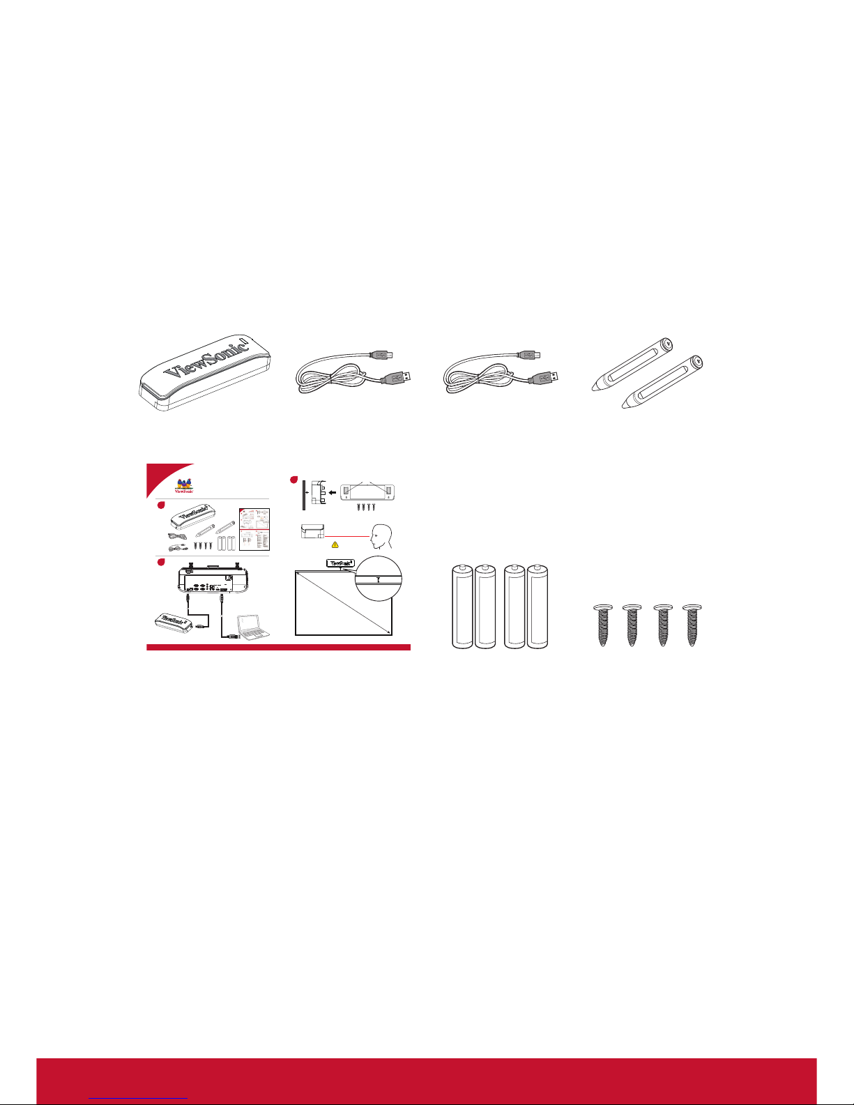
Packaged Items
Laser Module unit
x 1
Mini USB (6m) x 1 Mini USB (2m) x 1 IR Pen x 2
vTouch
PJ-vTouch-50s
Quick Start Guide
1
2
3
Magnet
Laser
x
Important
3 cm
Quick start guide Battery Screws
Page 9
2
IR Pen Battery Installation
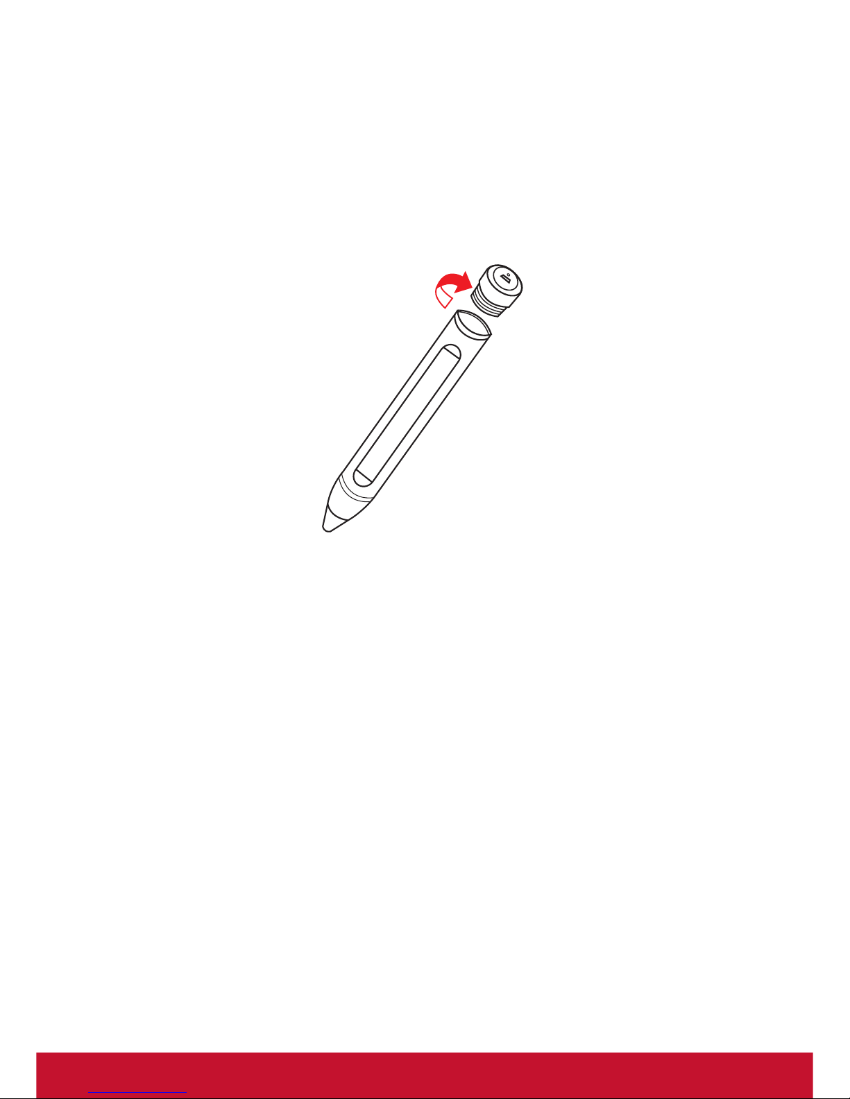
IR Pen uses two AAA batteries.
1. Twist off the top cover of the pen.
2. Insert two AAA batteries into the pen.
3. Twist the top cover of the pen back on.
Replace the battery when the pen begins to function incorrectly.
Notes for Using IR Pen
• Improper usage of the IR Pen may lead to malfunction; please avoid dropping or
disassembling the IR Pen.
• If the IR Pen comes in contact with water or any other type of liquid, switch the IR
Pen off immediately and wipe it dry.
• Avoid exposing the IR Pen to high temperatures or humidity.
Page 10
3
Setup Procedure
Laser Module Installation
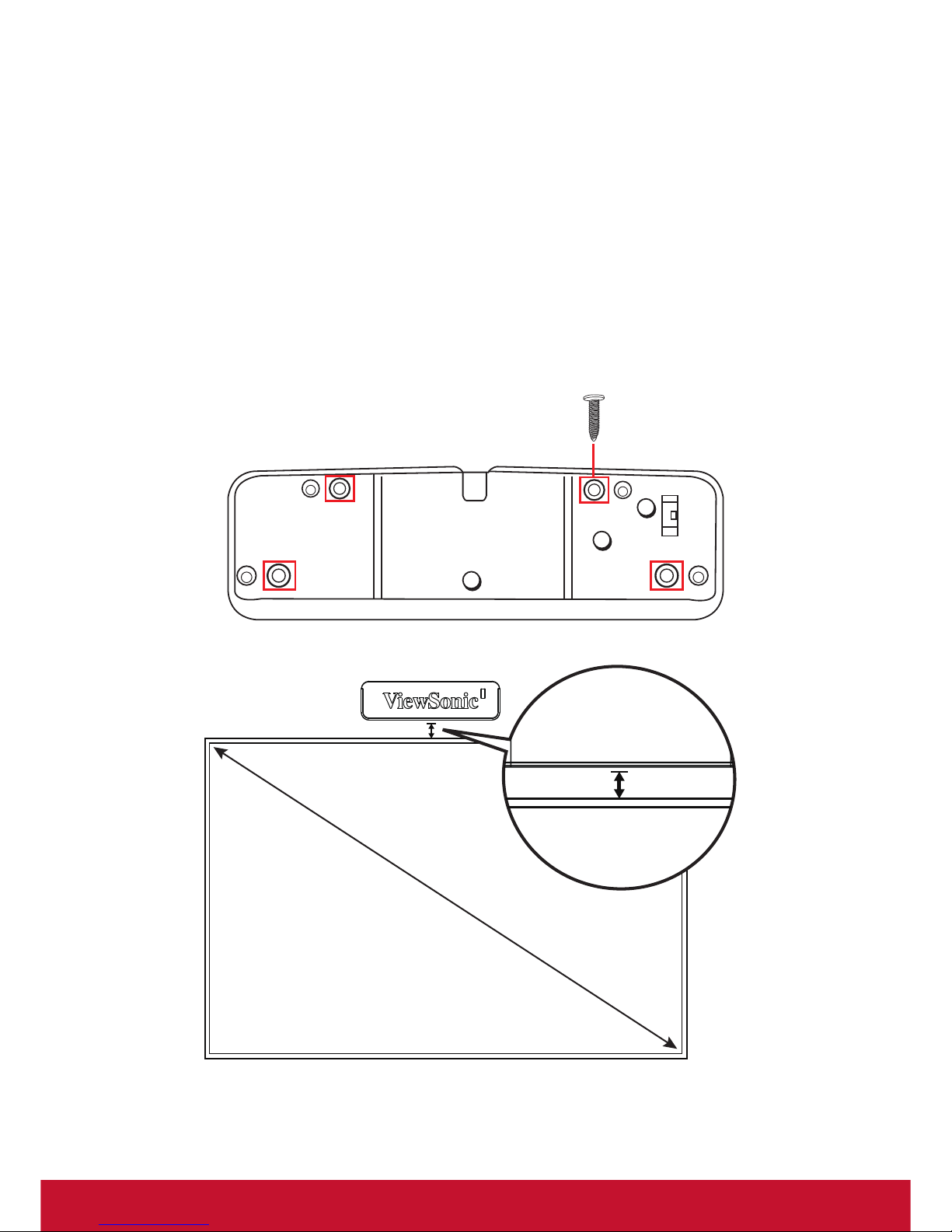
Install the Laser module approximately 3~5 centimeters above the projection surface
and align it with the center of the image. This product is equipped with magnets that
allow it to be attached to a whiteboard directly. If the module needs to be installed in
a location where magnets cannot be used to attach it, it can be xed into place using
screws.
Notice: For best results, do not install the module more than 5 centimeters higher
than the projection surface.
3 cm
Page 11
4
Connect Computer to Projector
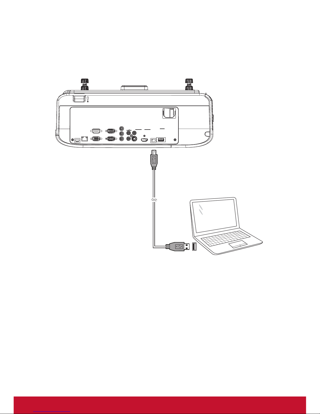
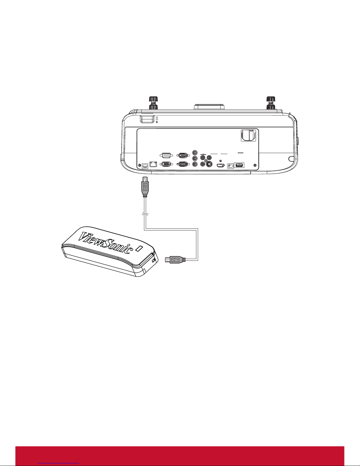
Connect a computer to the projector via a VGA or HDMI cable for image display. Use
the 6m standard USB cable to connect the computer (USB) and projector (mini USB)
for positioning and focus adjustment.
Page 12
5
Connect Laser Module to Projector
Connect the Laser Module (mini USB) to the projector (mini USB) using the included
2m USB cable. The indicator light will turn red once the Laser Module is working
correctly; if the indicator light has not turned red, this means that the Laser Module is
still not connected.
Page 13
6
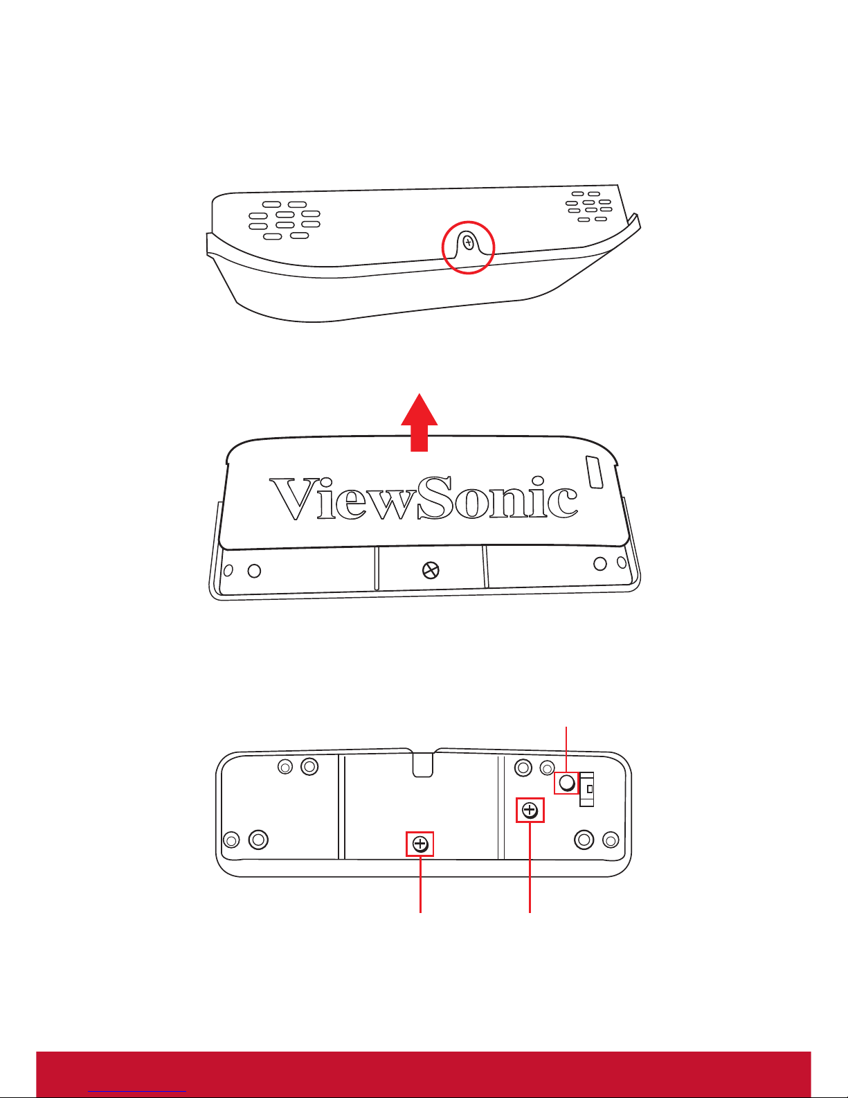
Adjust Laser Module
1. Loosen the screw on the laser module
2. Slide the top cover off of the laser module.
3. Press the Laser button to switch the module on. A horizontal beam of laser light
will appear to be used for calibration.
Gears A Gears B
Power
Page 14
7
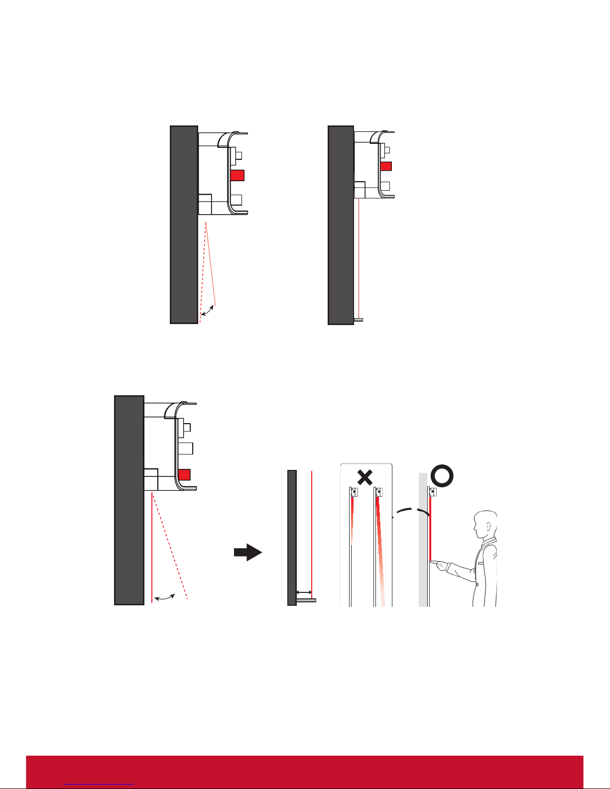
4. Check the distance between the whiteboard and the laser light. Use Gear B to
adjust the distance between the laser beam and the whiteboard to ensure that
the two are parallel.
Gears B
Gears B
5. Use Gear A to adjust the laser beam until the laser beam and the whiteboard are
approximately 5mm apart.
Gears A
5m
6. Turn the laser button off once calibration has been completed.
Page 15
8
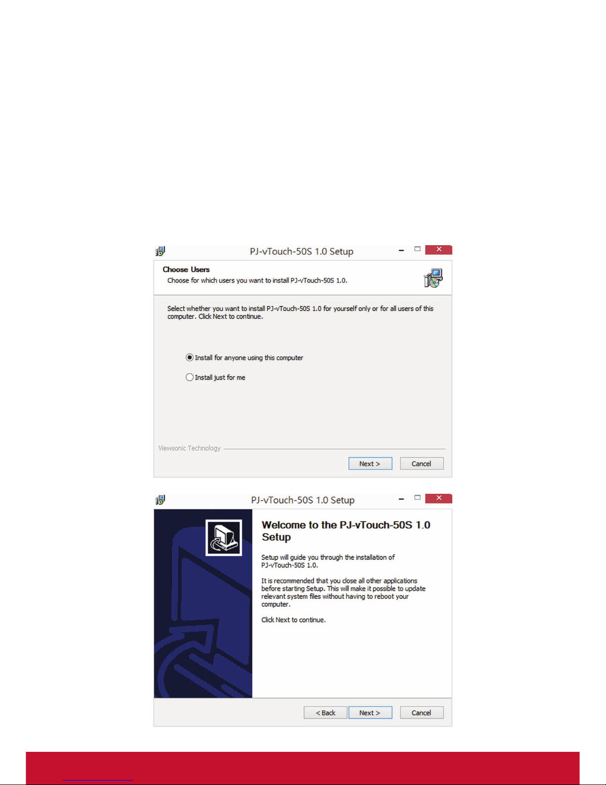
PJ-vTouch-50S Software Installation
OS required: Windows 7, Windows 8.1 or Windows 10.
1. Download the calibration software driver that corresponds to your projector via
the following website links.
• PS750W: http://vsweb.us/ps750w
• PS750X: http://vsweb.us/ps750x
• PS750HD: http://vsweb.us/ps750hd
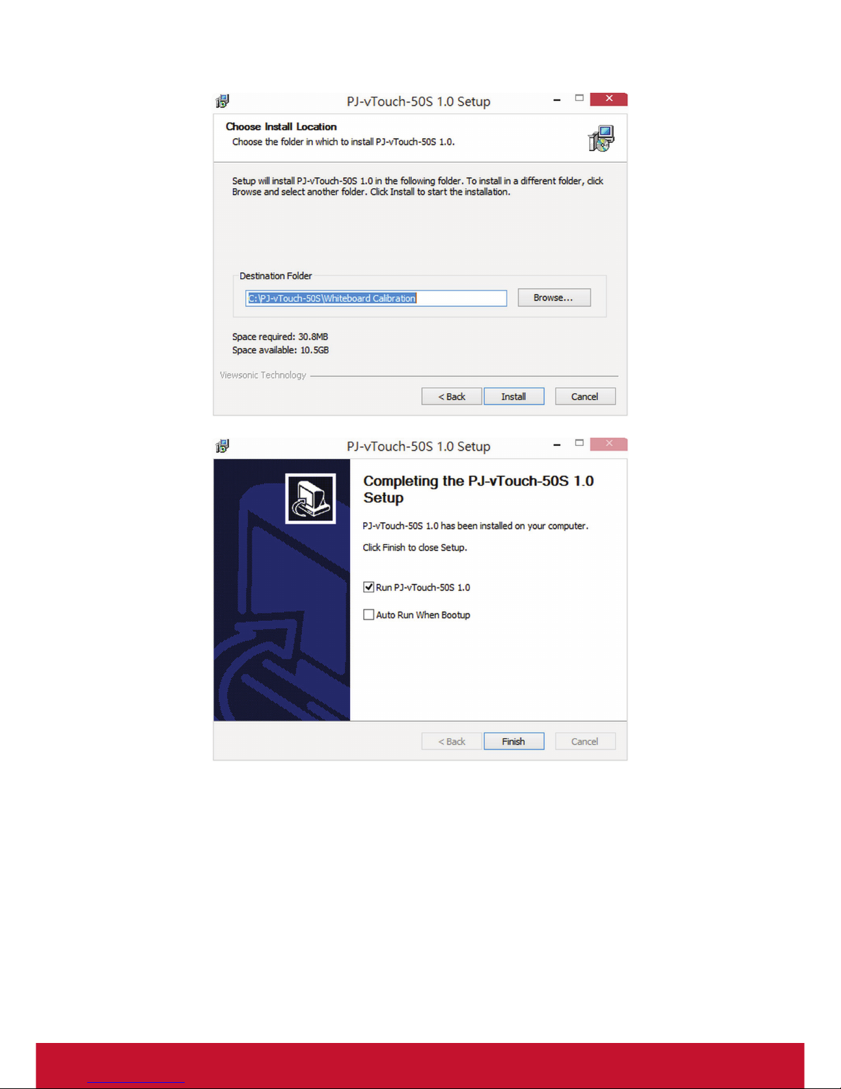
2. Double click “PJ-vTouch-50S.exe” and follow the instructions below to complete
the installation.
Page 16
9
Page 17
10
Startup Calibration Software
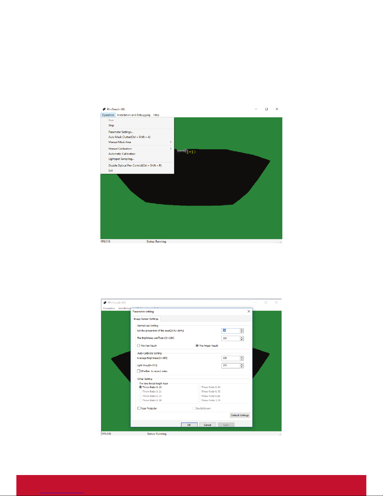
Double click the IWB icon to run PJ-vTouch-50S software
Calibration Menu Display
Operation Menu List
1. Run: Turn on the camera
2. Stop: Turn the camera off
3. Parameter Settings: Image sensor setting
Page 18

11
3.1 Normal Use Setting
• Set the proportion of the spot (20%~80%): Refers to the sensitivity of touch
reaction. The larger the value is, the lower the sensitivity becomes.
• The brightness coefficient (0~250): Refers to the sensitivity of camera CCD
sensor. The larger the value is, the higher the sensitive becomes.
• Pen touch: Only IR pens will be recognized by the touch screen.
• Finger touch: IR pens and fingers will both be recognized by the touch
screen.
Note: The default values for proportion of the spot and brightness coefficient are
different under pen touch mode and finger touch mode. Users can adjust these
values according to their preferences.
3.2 Auto Calibrate Setting
• Average brightness (0~255): Adjusts the brightness of camera images. Refers
to the sensor’s measurement of overall brightness from the “black and white
checkerboard” used during the automatic calibration process. The larger the
value is, the brighter the image will be.
• Light gray (0~255): Adjusts the contrast of camera images. Refers to the
overall contrast of the “black and white checkerboard” used by the calibration
software during the automatic calibration process. The larger the value is, the
greater the contrast between the black area and the white area in the “black
and white checkerboard” will be.
• Recording video: Record the auto calibration progress and save the file. In
the event that auto-calibration fails, users can provide this recorded video to
customer service.
3.3 Other Setting
• Focal length: For PS750 series, the default throw ratio is 0.15:1.
• Rear projector: If your projector is a rear projector, please choose this setting.
(Not for PS750 series)
4. Auto Mask Clutter (Ctrl + Shift + A): The program will mask all interfering light
automatically. When the single touch (mouse) is functioning abnormally, Auto
Mask Clutter will mask all interfering light.
5. Manual Mask Area: Click Manual Mask Area when the curser is functioning
abnormally. When the single touch (mouse) is functioning abnormally, Manual
Mask Area will mask interference spots.
6. Manual Calibration: Execute calibration manually when Automatic Calibration
fails or the cursor location and IR pen/finger position are not aligned.
7. Automatic Calibration: Execute calibration automatically.
Page 19

12
8. Lightspot Sampling: Lightspot sampling collection is to be performed after
calibration has been completed. Use finger or IR pen to touch the red square
until it turns green; repeat this until the process has been completed. Once the
cursor is working smoothly, execute Lightspot Sampling.
9. Disable Optical Pen Control (Ctrl + Shift + p): Enable and disable the touch
function.
10. 10. Exit: Exit the OSD
Page 20
13
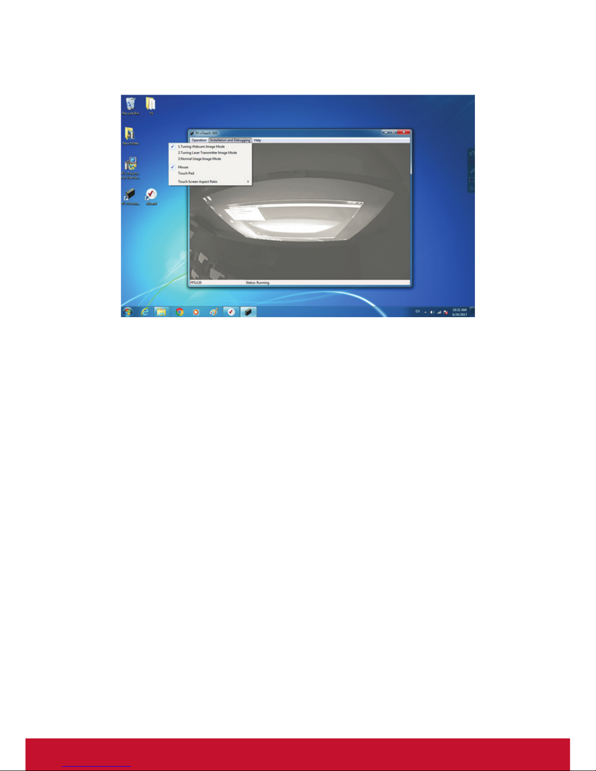
Installation and Debugging
1. Tuning Webcam Image Mode: Select this mode before calibration to see the
screen more clearly and make sure that the camera covers the entire screen
image.
2. Tuning Laser Transmitter Image Mode: Detect the sensitivity of lightspots.
Emitter emits an invisible laser film 5mm above the whiteboard. The size of
lightspot should be over 3*3mm.
3. Normal Usage Image Mode: After calibration, all operations can be done by
finger instead of the mouse.
4. Mouse: Only supports single touch.
5. Touch Pad: Supports up to 10-point simultaneous touch.
6. Touch Screen Aspect Ratio: Auto / 4:3/ 16:10/ 16:9. This setting needs to be the
same as the signal output resolution.
Page 21

14
Automatic Calibration
Click “Automatic Calibration” from operation menu. The image will be calibrated
automatically; the “Auto Calibrate Succeed” message will appear once Automatic
Calibration has been completed; if Automatic Calibration has failed, the
“Auto Calibrate Failed” message will appear. In this event, please refer to the
Troubleshooting Guide.
Manual Calibration
1. Touch the four corners of the projection screen with your finger or the IR Pen.
Make sure the light spots are positioned correctly on the four corners of screen
and that the size of each spot is over 3x3 pixels.
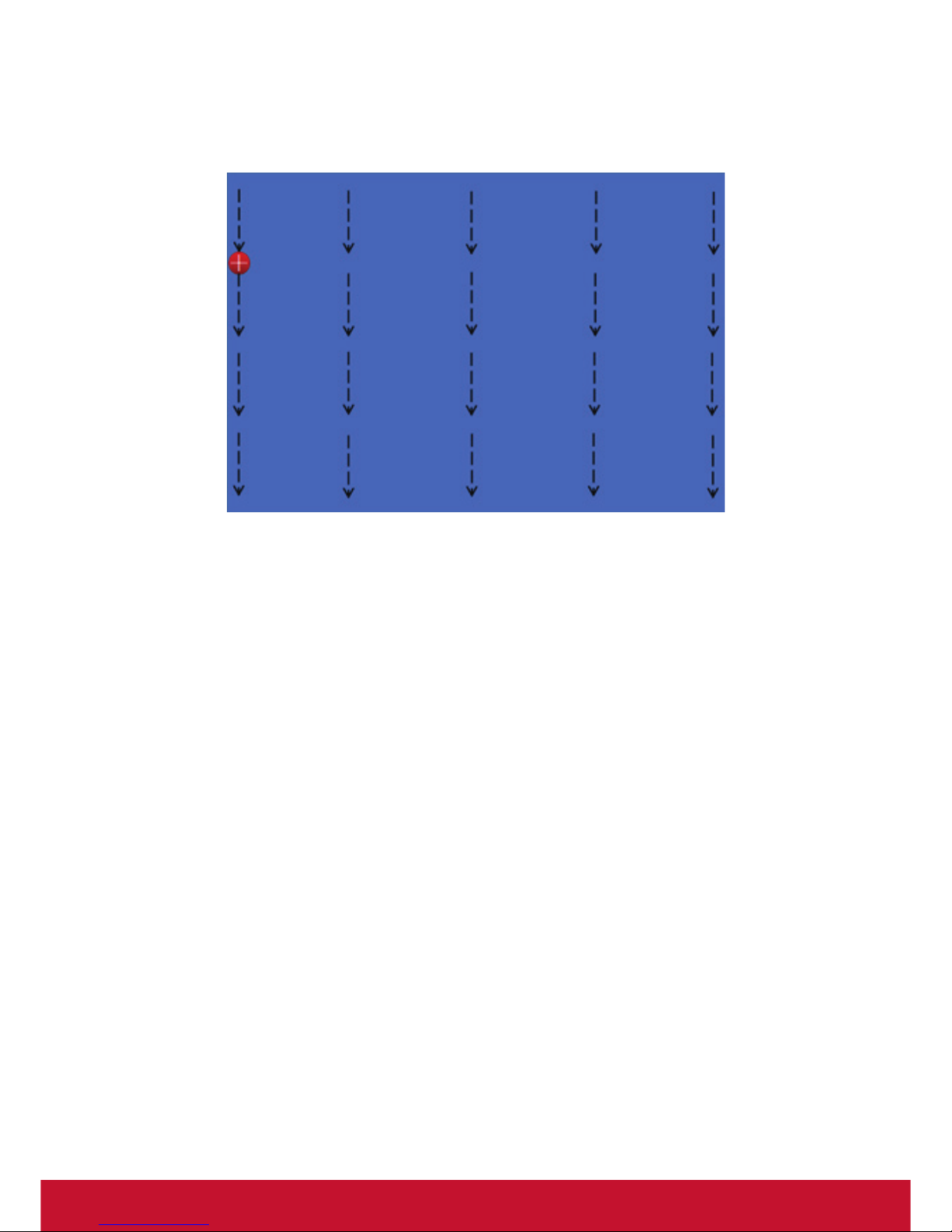
2. Select “Manual Calibration” (25 dots/36 dots) from operation menu. The
projected image on the screen will switch to the Manual Calibration screen and
the
icon will be displayed at the top left of the screen.
Page 22
15
3. Press 25 or 36 calibration dots on the screen using your finger or the IR Pen and
press the cross in the middle of each dot.
4. Once calibration has been completed successfully, the calibration software will
minimize onto the task tray; if the Manual Calibration has failed, please refer to
Troubleshooting Guide.
Page 23

16
Troubleshooting Guide
1. Finger touch operation is not working properly
(1) While using the calibration software, if the “Not a valid USB Key for finger
touch whiteboard” error message appears, please follow these steps: Open
“Device Management” and click the “Image Device” option. Check for a
hardware device named “TouchScreen Device ”.
(2) If you can recognize this device, please contact your dealer.
(3) If you cannot recognize this device, please check the connections for the
projector camera and the computer.
(4) If there is no problem with the connection, please reconnect to another USB
port.
2. After auto-calibration, the cursor’s position does not align with finger
position
Adjust the position of the laser module, Gear A and Gear B, and then do the
auto-calibration again.
3. Automatic Calibration process failure
(1) Select “Tuning Webcam Image Mode” from the “Installation and Debugging”
menu. Check if the webcam image is being displayable on the dazzling
screen, white screen, black screen, and flickering screen.
(2) If the webcam image is not being displayed properly, please contact your
dealer.
(3) If the webcam image status is showing up as normal, please make sure
there are no objects between the projection screen and the projector camera
during the Automatic Calibration process.
(4) Check that the IR-CUT switcher function is working properly.
(5) Adjust the image brightness accordingly and retry the Automatic Calibration.
(6) Ensure that there isn’t any strong ambient light interfering with the projector
camera or screen.
4. Inaccurate Calibration
(1) Check that the Laser Module installation and adjustments have been done
correctly.
(2) Redo Automatic Calibration.
(3) Redo Manual Calibration.
5. Manual Calibration failure
(1) If light spots are not shown in the four corners of projected screen after “Auto
Mask Clutter”, manually select “Mask Bitmap Edit” --> “Erase Mask Area”
and erase the area where there are no light spots being displayed until they
appear.
(2) Check that there are no other light spots on the projection screen while in the
“Auto Mask Clutter” process.
(3) The size of the light spot must be bigger than 3x3 pixels. If not, please redo
the manual calibration process with the IR Pen.
Page 24

17
Customer Support
For technical support or product service, see the table below or contact your reseller.
Note : You will need the product serial number.
Country/Region Website
T= Telephone
C = CHAT ONLINE
Email
Australia
New Zealand
www.viewsonic.com.au
AUS= 1800 880 818
NZ= 0800 008 822
Europe www.viewsoniceurope.com http://www.viewsoniceurope.com/eu/support/call-desk/
Latin America
(Argentina)
www.viewsonic.com/la/
C= http://www.viewsonic.com/
la/soporte/servicio-tecnico
Latin America
(Chile)
www.viewsonic.com/la/
C= http://www.viewsonic.com/
la/soporte/servicio-tecnico
Latin America
(Columbia)
www.viewsonic.com/la/
C= http://www.viewsonic.com/
la/soporte/servicio-tecnico
Latin America
(Mexico)
www.viewsonic.com/la/
C= http://www.viewsonic.com/
la/soporte/servicio-tecnico
Nexus Hightech Solutions, Cincinnati #40 Desp. 1 Col. De los Deportes Mexico D.F.
Tel: 55) 6547-6454 55)6547-6484
Other places please refer to http://www.viewsonic.com/la/soporte/servicio-tecnico#mexico
Latin America
(Peru)
www.viewsonic.com/la/
C= http://www.viewsonic.com/
la/soporte/servicio-tecnico
Puerto Rico &
Virgin Islands
www.viewsonic.com
T= 1-800-688-6688 (English)
C = http://www.viewsonic.com/
la/soporte/servicio-tecnico
Singapore/
Malaysia/
Thailand
Page 25

 Loading...