

ViewSonic VX712, VS10057 Service Manual

- 1 –
ViewSonic Corporation
Confidential - Do Not Copy VX712
Manufacture Date: Dec-20-05
Service Manual
ViewSonic VX712
Model No VS10057
17” Color TFT LCD Display
- 2 –
ViewSonic Corporation
Confidential - Do Not Copy VX712
Copyright
Copyright © 2005 by ViewSonic
®
Corporation. All rights reserved. No part of this publication
may be reproduced, transmitted, transcribed, stored in a retrieval system, or translated into
any language or manual or otherwise, without the prior written permission of ViewSonic
Corporation.
Disclaimer
ViewSonic
®
makes no representation or warranties, either expressed or implied, with respect
to the contents hereof and specifically disclaims any warranty of merchantability of fitness for
any particular purpose. Further, ViewSonic reserves the right to revise this publication and to
make changes from time to time in the contents hereof without obligation of ViewSonic to
notify any person of such revision or changes.
Trademarks
Optiquest is a registered trademark of ViewSonic Corporation.
ViewSonic
®
is a registered trademark of ViewSonic Corporation.
All other trademarks used within this document are the property of their respective owners.
Revision History
Revision Date Description of changes Approval
A01 Dec-20-05 Initial Release(T782KKWHBDVWABP) YG.WANG
A02 Apr-24-07
Add Different Part List
(T782KAWHBDVUABP/
T782KKWHBDVUABP)
YG.WANG
- 3 –
ViewSonic Corporation
Confidential - Do Not Copy VX712
TABLE OF CONTENTS
1. Precautions And Safety Notices 4
2. Specification 7
3. Front Panel Control And Indicators 10
4. Circuit Description 16
5. Adjustment Procedure 26
6. Troubleshooting Flow Chart 50
7. Recommended Spare Parts List 51
8. Different Part List 69
9. Exploded Diagram And Spare Parts List 71
10.Disassemble Process 72
11. Block Diagram 75
12. Schematic Diagram 76
13. PCB Layout Diagram 82

- 4 –
ViewSonic Corporation
Confidential - Do Not Copy VX712
1. Precautions And Safety Notices
1.1 SAFETY PRECAUTIONS
This monitor is manufactured and tested on a ground principle that a user’s safety comes
first. However, improper use or installation may cause damage to the monitor as well as the
user. Carefully go over the following WARNINGS before installing and keep this guide handy.
WARNINGS
.This monitor should be operated only at the correct power sources indicated on the label on
the rear end of the monitor. If you’re unsure of the power supply in your residence, consult
you local dealer or power company.
.Use only the special power adapter that comes with this monitor for power input.
.Do not try to repair the monitor your self as it contains no user-serviceable parts. This monitor
should only be repaired by a qualified technician.
.Do not remove the monitor cabinet. There is high-voltage parts inside that may cause electric
shock to human bodies, even when the power cord is unplugged.
.Stop using the monitor if the cabinet is damaged. Have it checked by a service technician.
.Put your monitor only in a clean, dry environment. If it gets wet, unplug the power cable
immediately and consult your service technician.
.Always unplug the monitor before cleaning it .Clean the cabinet with a clean, dry cloth. Apply
non-ammonia based cleaner onto the cloth, not directly onto the glass screen.
.Keep the monitor away from magnetic objects, motors, TV sets, and transformer.
.Do not place heavy objects on the monitor or power cord.
1.2 PRODUCT SAFETY NOTICE
Many electrical and mechanical parts in this chassis have special safety visual inspections
and the protection afforded by them cannot necessarily be obtained by using replacement
components rated for higher voltages, wattage, etc. Before replacing any of these
components read the parts list in this manual carefully. The use of substitute replacement
parts which do not have the same safety characteristics as specified in the parts list may
create shock, fire ,or other hazards.
1.3 SERVICE NOTES
1. When replacing parts or circuit boards, clamp the lead wires around terminals before
soldering.
2. When replacing a high wattage resistor(more than 1W of metal oxide film resistor) in circuit
board, keep the resistor about 5mm away from circuit board.
3. Keep wires away from high voltage, high temperature components and sharp edges.
4. Keep wires in their original position so as to reduce interference.
5. Usage of this product please refer to also user’s manual.
- 5 –
ViewSonic Corporation
Confidential - Do Not Copy VX712
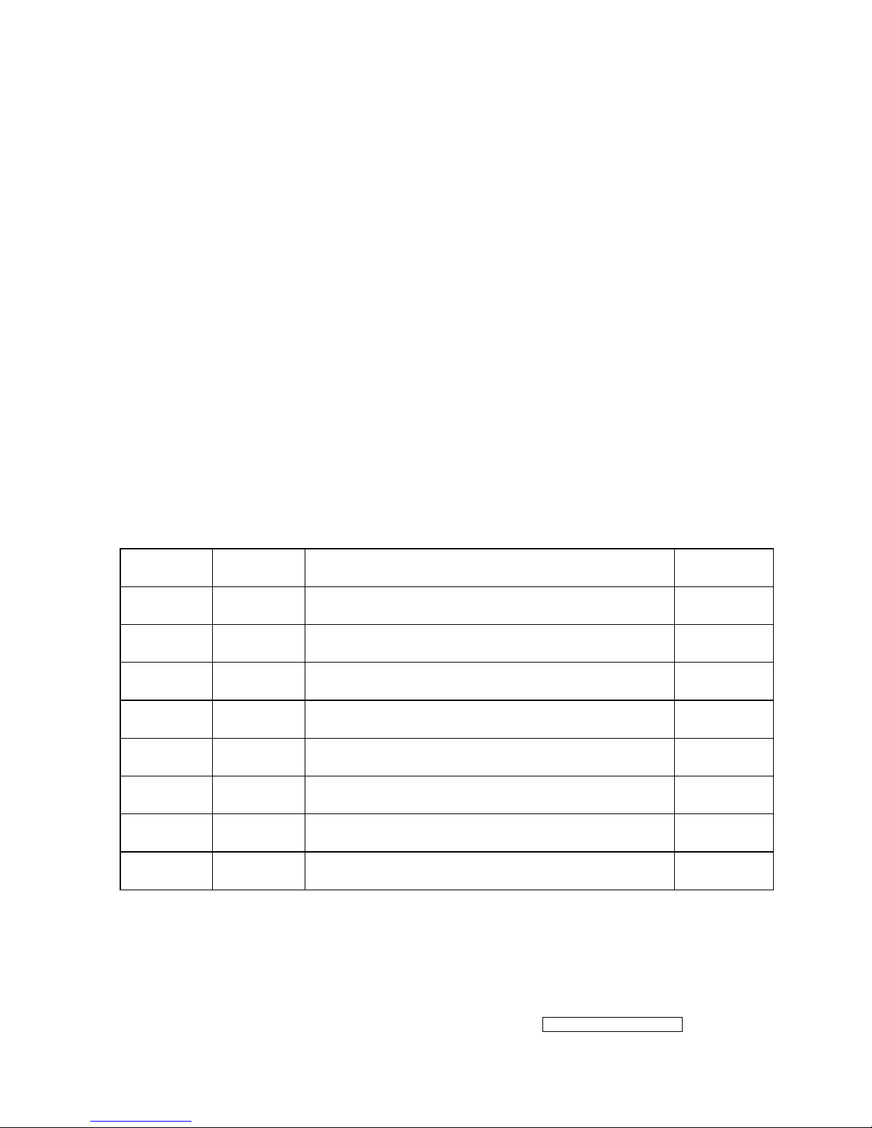
1.4 HANDING AND PLACING METHODS
Correct Methods: Incorrect Methods:
Only touch the metal frame of the LCD
panel or the front cover of the monitor. Do
not touch the surface of the polarizer.
Surface of the LCD panel is pressed by fingers
and that may cause “Mura.”
Take out the monitor with cushions
Taking out the monitor by grasping the LCD
panel. That may cause “Mura.”
- 6 –
ViewSonic Corporation
Confidential - Do Not Copy VX712
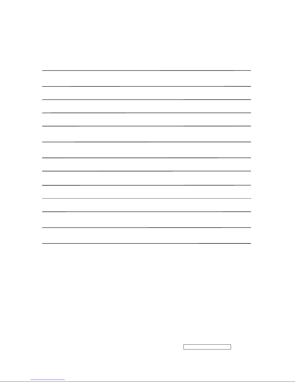
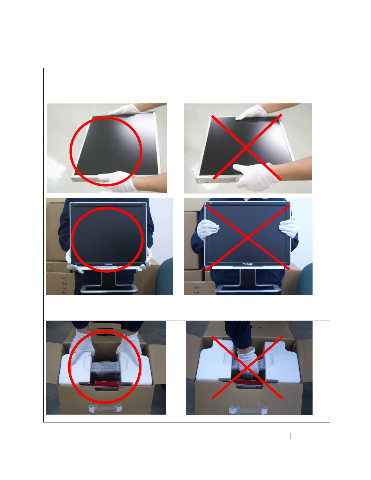
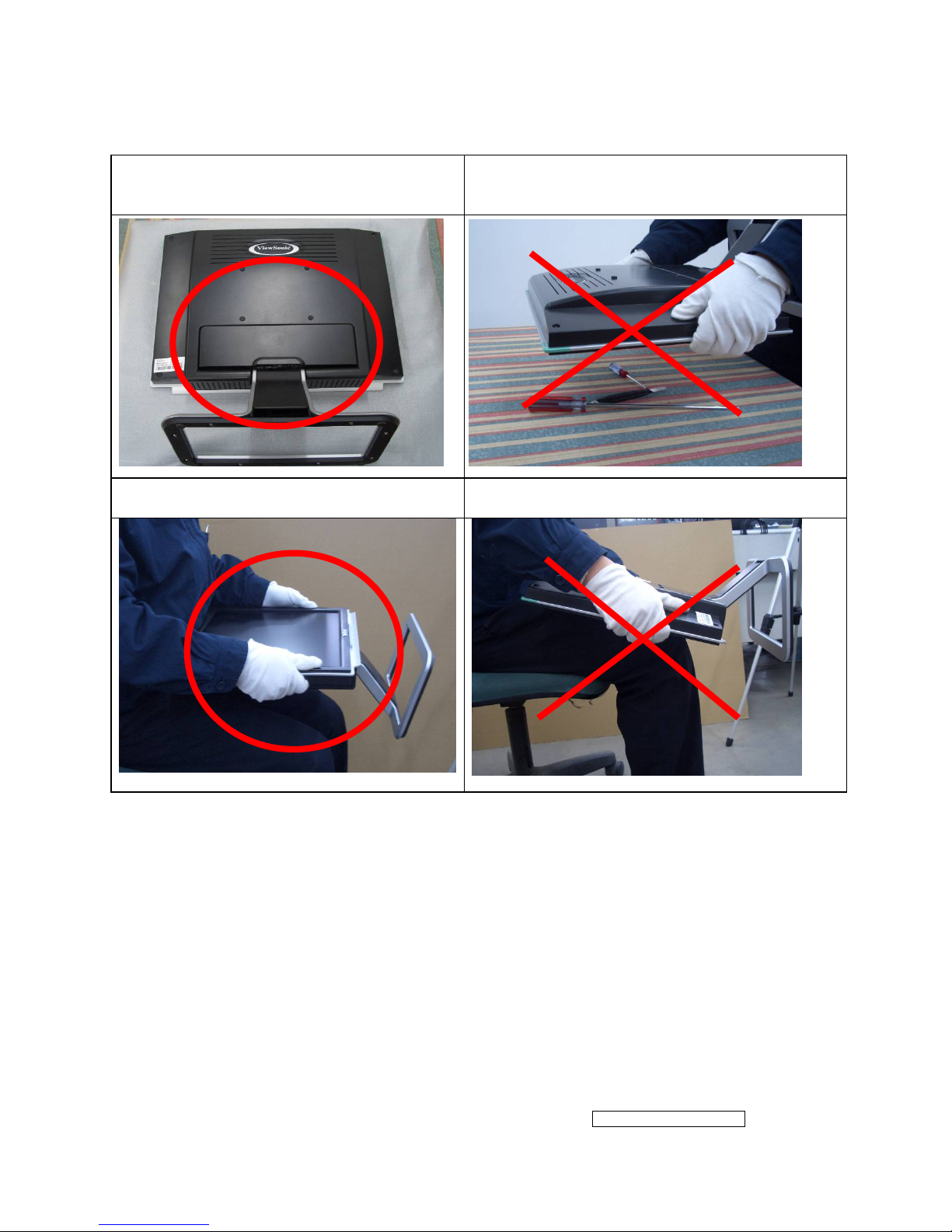
Place the monitor on a clean and soft foam
pad.
Placing the monitor on foreign objects. That
could scratch the surface of the panel or cause
“Mura.”
Place the monitor on the lap, the panel
surface must be upwards.
The panel is placed facedown on the lap. That
may cause “Mura.”
- 7 –
ViewSonic Corporation
Confidential - Do Not Copy VX712
2. Specification
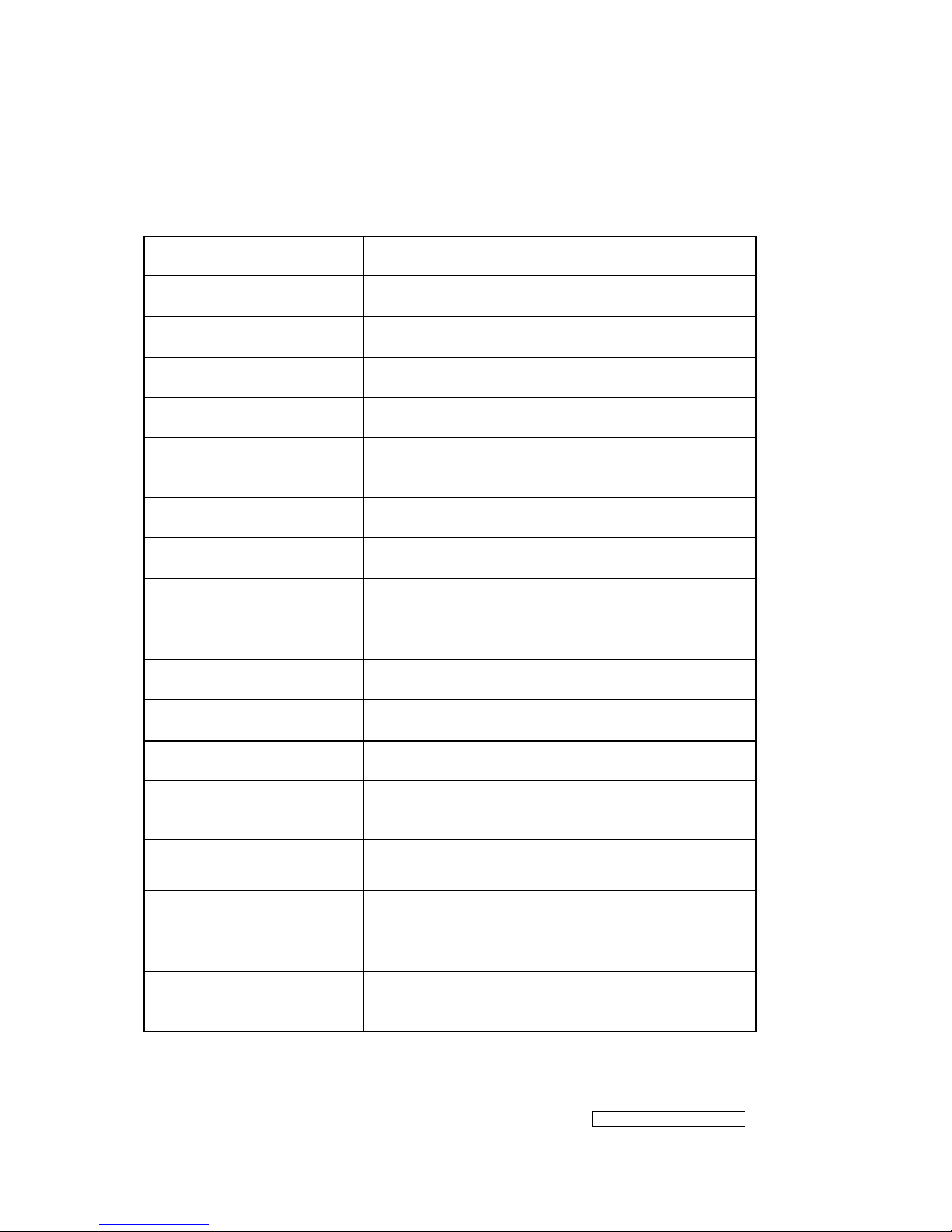
2.1 PRODUCT SPECIFICATIONS
LCD Panel 17.0” TFT
Recommend Resolution 1280 x1024@60Hz
Input Signal Analog / Digital
Pixel Dimension 0.264(H) x 0.264(V)mm
LCD Display Color 16.2M Colors (RGB 6-bit+FRC data)
Viewing Angle
Horizontal: 150
°
Vertical: 135 °
Contrast Ratio 700:1 (Typ.)
Brightness 300 cd/㎡(Typ.)
Response Time 8ms(Typ.)
Active Display Area 337.9 (H) x 270.3 (V)
Maximum Pixel Clock 135 MHz
Horizontal Frequency 30 – 82 kHz
Vertical Refresh Rate 50 – 75 Hz.
Temperature
Operating: 0°C to +40°C
Storage: -20°C to +60°C
Audio Input 1 x 2 Watts
Power Management
Energy Star compliant VESA
DPMS compatible
<1 W
Power
Input Voltage : 90V~264V
Consumption: 40 Watts(Max.) 35 Watts(Typ.)
- 8 –
ViewSonic Corporation
Confidential - Do Not Copy VX712
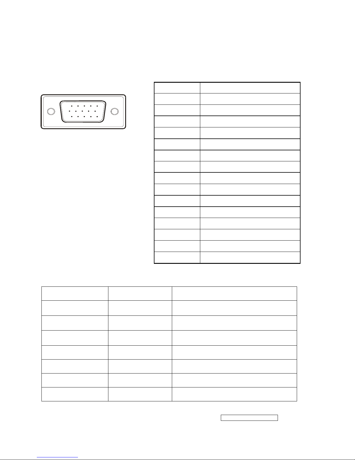
2.2 INTERFACE DESCRIPTION
D-SUB 15 PIN CONNECTOR
15
6
10
11 15
SIGNAL LEVEL
CONNECTOR SIGNAL DESCRIPTION
R Red
0.7
vp-p(VIDEO)
G Green
0.7
vp-p(VIDEO)
B Blue
0.7
vp-p(VIDEO)
H H/Sync TTL positive or negative
V V/Sync TTL positive or negative
SDA DDC1/2B TTL
SCL DDC1/2B TTL
Pin Number Pin Function
1 Red video input
2 Green video input
3 Blue video input
4 No Connection
5 Ground
6 Red video ground
7 Green video ground
8 Blue video ground
9 +5V
10 H/V sync ground
11 No connection
12 (SDA)
13 Horizontal sync (Composite sync)
14 Vertical sync
15 (SCL)
- 9 –
ViewSonic Corporation
Confidential - Do Not Copy VX712
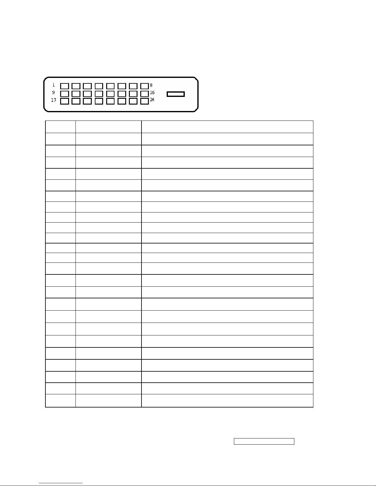
DVI-D 24 PIN CONNECTOR
Pin No. Signal Name Description
1 RX2- TMDS negative differential input, channel 2
2 RX2+ TMDS positive differential input, channel 2
3 GND Logic Ground
4 Reserved 4 Reserved. No connection
5 Reserved 5 Reserved. No connection
6 DDC-CLK DDC2B Clock
7 DDC-DAT DDC2B Data
8 Reserved 8 Reserved. No connection
9 RX1- TMDS negative differential input, channel 1
10 RX1+ TMDS positive differential input, channel 1
11 GND Logic Ground
12 Reserved 12 Reserved. No connection
13 Reserved 13 Reserved. No connection
14 VCCX Power
15 GND Logic Ground
16 SENS SENSE Pin, Pull High
17 RX0- TMDS negative differential input, channel 0
18 RX0+ TMDS positive differential input, channel 0
19 GND Logic Ground
20 Reserved 20 Reserved. No connection
21 Reserved 21 Reserved. No connection
22 GND Logic Ground
23 RXC+ TMDS positive differential input, reference clock
24 RXC- TMDS negative differential input, reference clock
- 10 –
ViewSonic Corporation
Confidential - Do Not Copy VX712
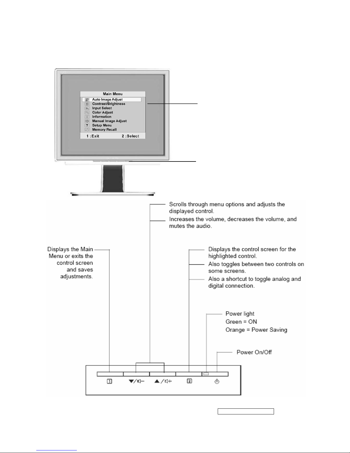
3. Front Panel Function Control Description
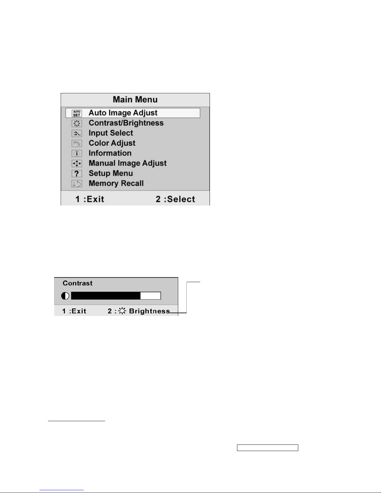
Main Menu
with OSD controls
Front Control Panel
shown below in detail
- 11 –
ViewSonic Corporation
Confidential - Do Not Copy VX712
Do the following to adjust the display setting:
1. To display the Main Menu, press button: [1]
NOTE: All OSD menus and adjustment screens disappear automatically after about 30
seconds. This is adjustable through the OSD timeout setting in the setup menu.
2. To select a control to adjust, press ▲ or ▼ to scroll up or down the Main Menu.
3. After the desired control is selected, press button [2]. A control screen like the one shown
below appears.
4. To adjust the setting, press the up ▲ or down ▼ buttons.
5. To save the adjustments and exit the menu, press button [1] twice.
The following tips may help you optimize your display:
.Adjust your computer’s graphic card so that is outputs a 1280×1024@60Hz video signal to the
LCD display.(Look for instructions on “changing the refresh rate” in the graphics card’s user
guide.)
.If necessary, make small adjustments using H. Position and V. Position until the screen image is
completely visible.
(The black border around the edge of the screen should barely touch is
illuminated “active area” of the LCD display.)
The line at the bottom of the screen shows
the current functions of buttons 1 and 2:
Exit or select the Bri
g
htness control.

- 12 –
ViewSonic Corporation
Confidential - Do Not Copy VX712
Main Menu Control
Adjust the menu items shown below by using up ▲ or down ▼ buttons.
Control explanation:
Auto Image Adjust automatically sizes, centers, and fine tunes the video signal
to eliminate waviness and distortion. Press the [2] button to obtain a shaper
image.
Note:
1. Auto Image Adjust works with most common video cards. If this function does
not work on your LCD display, then lower the video refresh rate to 60 Hz and
set the resolution to its pre-set value.
2. The Auto Image Adjust and most Manual Image Adjust functions are not
available for DVI input.
Contrast adjust the different between the image background
(black level) and the foreground (white level).
Brightness adjusts background black level of the screen image.
Input Select allows the user to toggle between an analog and a digital signal.
Color Adjust provides several color adjustment modes, including preset color
temperatures and a User Color mode which allows independent adjustment of
red (R), green (G), and blue (B). The factory setting for this product is 6500K
(6500 Kelvin).
sRGB — sRGB is quickly becoming the industry standard for color management,
with support being included in many of the latest applications. Enabling this
setting allows the LCD display to more accurately display colors the way they
were originally intended. Enabling the sRGB setting will cause the Contrast and
Brightness adjustments to be disabled.
9300K — Adds blue to the screen image for cooler white (used in most office
setting with fluorescent lighting).
- 13 –
ViewSonic Corporation
Confidential - Do Not Copy VX712
6500K — Adds red to the screen image for warmer white and richer red.
5400K — Adds green to the screen image for a darker color.
User Color — Individual adjustments for red (R), green (G), and blue (B).
1. To select color (R, G or B) press button [2].
2. To adjust selected color , press ▲ or ▼.
Important: If you select RECALL from the Main Menu when the product is set to
a Preset Timing Mode, colors return to the 6500K factory preset.
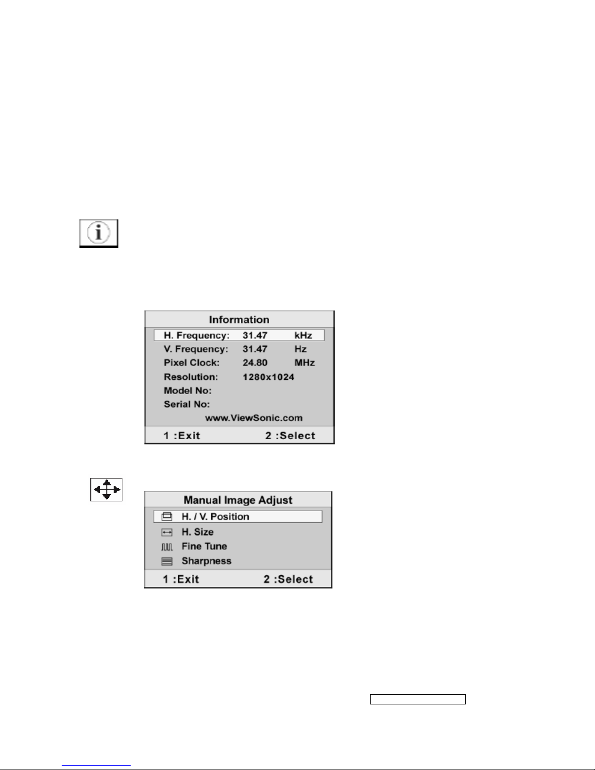
Information displays the timing mode (video signal input) coming from the
graphics card in the computer, the LCD model number, the serial number, and
the ViewSonic
®
website URL. See your graphics card’s user guide for instructions
on changing the resolution and refresh rate (vertical frequency).
NOTE: VESA 1280×1024@60Hz (recommended) means that the resolution is
1280×1024 and the refresh rate is 60Hz.
Manual Image Adjust displays the Manual Image Adjust menu.
The Manual Image Adjust controls are explained below:
H./V. Position(Horizontal/Vertical Postion) moves the screen image left or right
and up or down.
H. Size(Horizontal Size) adjusts the width of the screen image.

- 14 –
ViewSonic Corporation
Confidential - Do Not Copy VX712
Fine Tune sharpens focus by aligning the text and/or graphics with pixel
boundaries.
Sharpness adjusts the clarity and focus of the screen image.
Setup Menu display the menu shown below.
The Setup Menu controls are explained below:
Language Select allows the user to choose the language used is the menus and
control screens.
Resolution Notice displays the Resolution Notice menu shown below.
Resolution Notice advises the optimal resolution to use.
OSD Position allows the user to move the OSD menus and control screens.
OSD Timeout sets the length of time the OSD screen is displayed. For example,
with a “15 second” setting, if a control is not pushed within 15 seconds, the display
screen disappears.
OSD Background allows you to turn the OSD background On or Off.
- 15 –
ViewSonic Corporation
Confidential - Do Not Copy VX712
Memory Recall returns adjustments back to factory settings if the display is
operating in a factory Preset Timing Mode listed in the Specifications of this
manual.
Exception: This control does not affect changes mode with the User Color control,
Language Select or Power Lock setting.
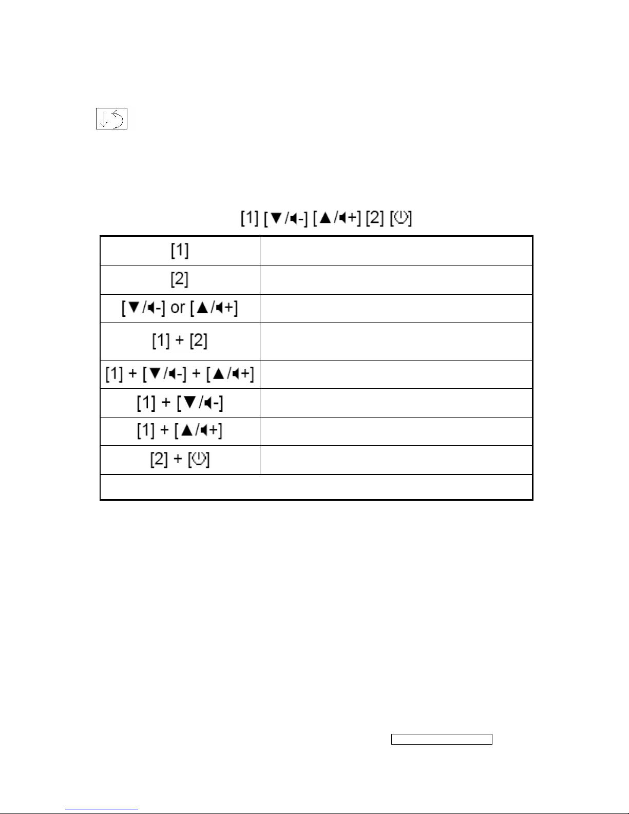
Short Cut Key
Function key: 5 keys
Main Menu
Input toggle (Analog / Digital)
Audio Adjust
Toggle 720x400 and 640x400 mode when input
720x400 or 640x400 mode
White Balance. (Not shown on user’s guide)
Power Lock
OSD Lock
Factory Mode
Remark : All the short cuts function are only available while OSD off.
- 16 –
ViewSonic Corporation
Confidential - Do Not Copy VX712
4. Circuit Description
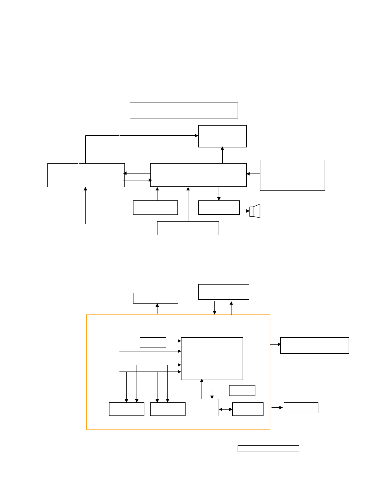
4.1 LCD MONITOR DESCRIPTION
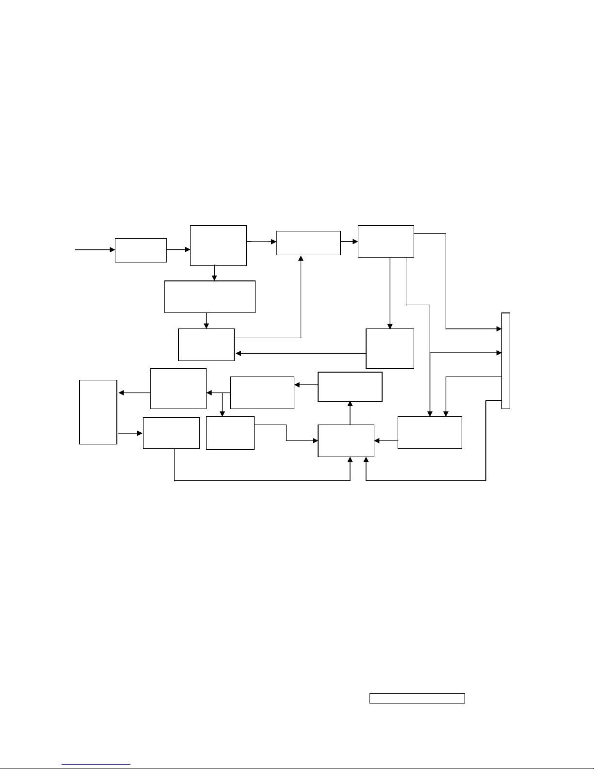
The LCD MONITOR will contain a Main Board, an Power Board, an Audio Board, Key
Board which house the flat panel control logic, brightness control logic and DDC.
4.2 MAIN BOARD BLOCK FUNCTION DESCRIPTION
The main board contains panel control logic, brightness control logic, DDC and DC
convert DC circuit and so on.
Power Board
(Include: adapter, inverter)
Flat Panel and
CCFL backlight
Main Board
Key Board
RS232 Connector
For white balance
adjustment in factory
mode
HOST Computer
CCFL Drive.
AC-IN
100V-240V
Video signal, DDC
Monitor Block Diagram
R
G
B
H
V
SDA
SCL
OSC
Backlight and Panel
PWPC board
EPROM EPROM
Keyboard
RTD2523
Audio Board
A
udio board
MCU
EPROM
OSC
- 17 –
ViewSonic Corporation
Confidential - Do Not Copy VX712
4.3 PWPC BOARD BLOCK FUNCTION DESCRIPTION
PWPC board combines to adapter and inverter, Adapter which commonly consists of
bridge rectifier and filter, start circuit, PWM control circuit, protection circuits and convert to
12V, 5V DC voltage by input 90V-240V AC voltage that provide power supply for each
chips in the main board and inverter. Inverter is DC TO AC circuit. It changes the 12v DC
of power supply to about 600-800v AC that drives the backlight. It mostly consists of
starting circuit, PWM controller, DC changing circuit, LC surging circuit, output circuit and
protection circuit etc.
AC input
EMI filter
Bridge
Rectifier
and Filter
Start Circuit
R903, R904,R905
PWM
Control IC
Over
Vol tage
Protect
Rectifier
CMOS
ON/OFF
Control
PWM
Control IC
Feedback
Circuit
OSC and
Output
Circuit
DC Convert
Circuit
MOSFET
Q203
Over
Voltage
CN902
Transformer
Lamp
5V
12V
ON/OFF
DIM
- 18 –
ViewSonic Corporation
Confidential - Do Not Copy VX712
4.4 INTRODUCTION OF IC
RTD2523-LF(IC101): integrate ADC, OSD, SCALER, LVDS, convert analog RGB into
digital and room and shrink scaling output to LCD panel.
PIN Function:
Pin Symbol Description
1 XO Reference clock output
2 XI Reference clock input
3 DPLL_GND Ground for digital PLL
4 DPLL_VDD Power for digital PLL(3.3v)
5 APLL_VDD Power for multi-phase PLL(3.3v)
6 PLL_TEST1 Test Pin 1/IRQ#
7 PLL_TEST2 Test Pin 2/Power-on-latch for crystal
out Frequency
8 APLL_GND Ground for multi-phase PLL
9 PWM1/TMDS_TST PWM1/TMDS_TEST Pin/Power-on
latch for serial/parallel port
11、13、
19、26
TMDS_VDD 3.3V
12 EXT_RES Impedance Match Reference
14 RX2P Differential Data Input
15 RX2N Differential Data Input
17 RX1P Differential Data Input
18 RX1N Differential Data Input
20 RX0P Differential Data Input
21 RX0N Differential Data Input
23 RXCP Differential Data Input
24 RXCN Differential Data Input
51 PWM2/TCON[2]/S[3] PWM2/TCON[2]/SDIO[3]
55 PWM2/TCON[13]/COUT PWM2/TCON[13]/Crystal out
113 PWM2/TCON[12]/COUT PWM2/TCON[12]/Crystal out
47 PWM1/DDCSDA/TCON[1]/BBLU[0] PWM1/DDC serial control I/F data
input/output/TCON[4]
125 PWM1/DDCSDA2/TCON[7] PWM1/DDC serial control I/F data
input/output/TCON[7]
112 PWM0 / REFCLK PWM0(In/out)test pin for DCKL/Video
8 even-odd signal
54 SDIO[0] Serial control I/F data in/Parallel port
data[0]
53 SDIO[1]/TCON[4]/BBLU[0] Parallel port data[1]/TCON[4]/TTL
BBLU[0]
52 SDIO[2]/TCON[3]/BBLU[1] Parallel port data[2]/TCON[3]/TTL
BBLU[1]
51 SDIO[3]/PWM2/TCON[2] Parallel port data[1]/TCON[4]/PWM2
50 SCLK Serial control I/F clock
- 19 –
ViewSonic Corporation
Confidential - Do Not Copy VX712
AIC1084-33PM (U101): DC power convert, used to 5v convert 3.3v.
RT9164(U102): DC power convert, used to 5v convert 2.5v.
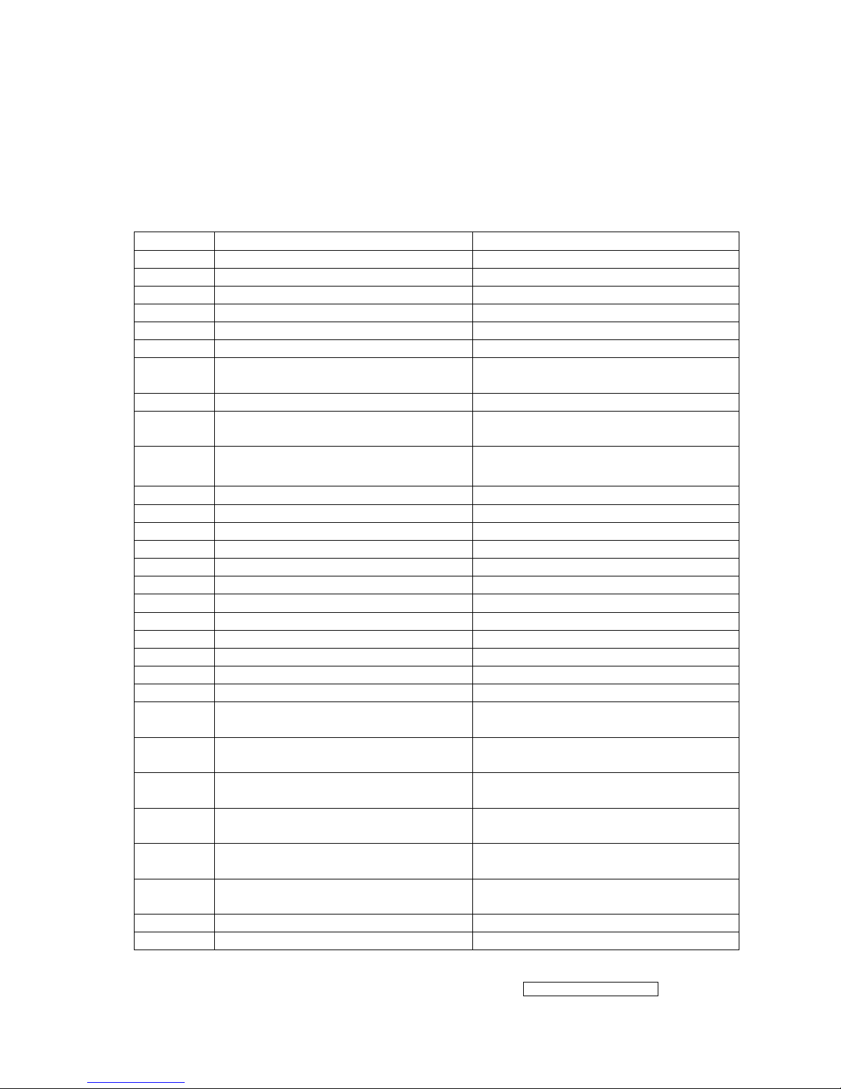
MTV512GMV64(U104):The MTV512M micro-controller is an 8051 CPU core embedded
device especially tailored for flat panel display applications. It includes an 8051
CPU core, 768-byte SRAM, 4 channels of 6-bit ADC, 3 external
counters/timers, 6 channels of PWM DAC, VESA DDC interface, and a
64K-byte internal program Flash-ROM memory.
111 SCSB Serial control I/F chip select
56 RESET RESET putput for Micron
46 DDCSCL / TCON[0] / BBLU[1] DDC serial control I/F clock/TCON[0]/
TTL BBLU[1]
47 DDCSDA / TCON[1] / pWM1 /
BBLU[0]
DDC serial control I/F data input/out/
CON[1] / Pwm1/TTL BBLU[0]
126 DDCSCL2 / TCON[5] DDC serial control I/F clock /
TCON[5]
125 DDCSDA2 / TCON[7] / pWM1 DDC serial control I/F data
input/out/TCON[7] / pWM1
28 ADC_REFIO ADC band-gap voltage de-coupling
29 ADC_VDD Analog power(3.3v)
30 BLUE+ Analog input from BLUE channel
31 BLUE- Analog input ground from BLUE
channel
33 SOG / ADC_ TEST SOG in / ADC test pin
34 GREEN+ Analog input from GREEN channel
35 GREEN- Analog input ground from GREEN
channel
36 ADCB_VDD Analog power(3.3V)
37 RED+ Analog input from RED channel
38 RED- Analog input ground from RED
channel
41 ADC_VDD Analog power(3.3V)
42 AHS Analog HS input
43 AVS Analog VS input
49、121 3.3V Power VCCIO: 2
58、71、
83、95、
110
3.3V Power PVCC: 5
45、69、
98、127
2.5V Power VCCK: 4
- 20 –
ViewSonic Corporation
Confidential - Do Not Copy VX712
- 21 –
ViewSonic Corporation
Confidential - Do Not Copy VX712
PIN Function
Pin No.
Name
PLCC QFP
Description
NC 1 39 No connection
DA0/P5.0 2 40 PWM DAC output/General purpose I/O (open drain)
DA1/P5.1 3 41 PWM DAC output/General purpose I/O (open drain)
DA2/P5.2 4 42 PWM DAC output/General purpose I/O (open drain)
DA3/P5.3 5 43 PWM DAC output/General purpose I/O (open drain)
DA4/ P5.4 6 44 PWM DAC output/General purpose I/O (open drain)
DA5/P5.5 7 1 PWM DAC output/General purpose I/O (open drain)
P5.6/HSCL2 8 2 General purpose I/O/Slave IIC1 SCL2 (open drain)
P5.7/HSDA2 9 3
General purpose Output/Slave IIC1 SDA2 (open
drain)
RST 10 4 High Active RESET
HSCL1/P3.0/RXD 11 5
Slave IIC clock/General purpose I/O/Rxd (open
drain)
HSDA1/P3.1/TXD 13 7 Slave IIC data/General purpose I/O/Txd (open drain)
CN 12 6 No connection
P3.2/INT0 14 8
General purpose I/O/External interrupt 0 (Standard
8051)
P3.3/INT1 15 9
General purpose I/O/External interrupt 1 (Standard
8051)
P3.4/T0 16 10
General purpose I/O/T0 Ext. Counter/Timer 0
(Standard 8051)
P3.5/T1 17 11
General purpose I/O/T1 Ext. Counter/Timer 1
(Standard 8051)
P7.6/CLKO2 18 12 General purpose I/O /Clock out 2 (CMOS)
P7.7 19 13 General purpose I/O (CMOS)
X2 20 14 Crystal Out
X1 21 15 Crystal In
VSS 22 16 Ground
NC 23 17 No connection
P6.0/AD0 24 18
General purpose I/O (CMOS) /6-bit ADC channel 0
input
P6.1/AD1 25 19
General purpose I/O (CMOS) /6-bit ADC channel 1
input
P6.2/AD2 26 20
General purpose I/O (CMOS) /6-bit ADC channel 2
input
P6.3/AD3 27 21
General purpose I/O (CMOS) /6-bit ADC channel 3
input
P6.4 28 22 General purpose I/O (CMOS)
P6.5 29 23 General purpose I/O (CMOS)
P6.6/CLKO1 30 24 General purpose I/O/CLKO1 (CMOS)
P6.7 31 25 General purpose I/O (CMOS)
VSYNC 32 26 VSYNC input
- 22 –
ViewSonic Corporation
Confidential - Do Not Copy VX712
NC 33 27 No connection
NC 34 28 No connection
NC 35 29 No connection
P1.7 36 30 General purpose I/O (Standard 8051/CMOS)
P1.6 37 31 General purpose I/O (Standard 8051/CMOS)
P1.5 38 32 General purpose I/O (Standard 8051/CMOS)
P1.4 39 33 General purpose I/O (Standard 8051/CMOS)
P1.3 40 34 General purpose I/O (Standard 8051/CMOS)
P1.2 41 35 General purpose I/O (Standard 8051/CMOS)
P1.1 42 36 General purpose I/O (Standard 8051/CMOS)
P1.0/ET2 43 37
General purpose I/O/External Counter/Timer2
(Standard 8051/CMOS)
VCC 44 38 3.3V power
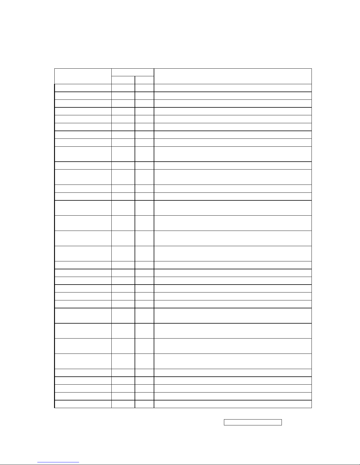
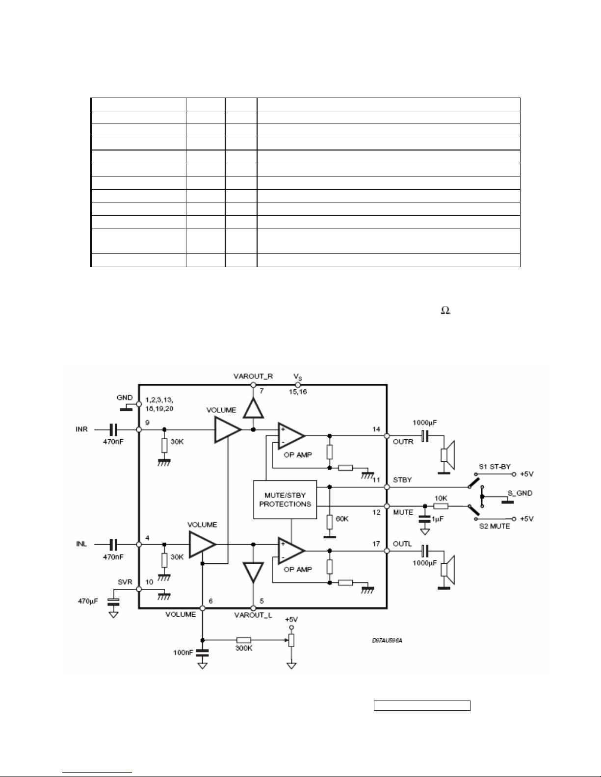
TDA7496L(U201): The TDA7496L is a stereo 2W+2W class AB power amplifier
assembled in the @ Powerdip, driving speakers as low as 8
. The function of
each pin and the inside circuit diagram are as follows:
Block Diagram
- 23 –
ViewSonic Corporation
Confidential - Do Not Copy VX712
PIN Function
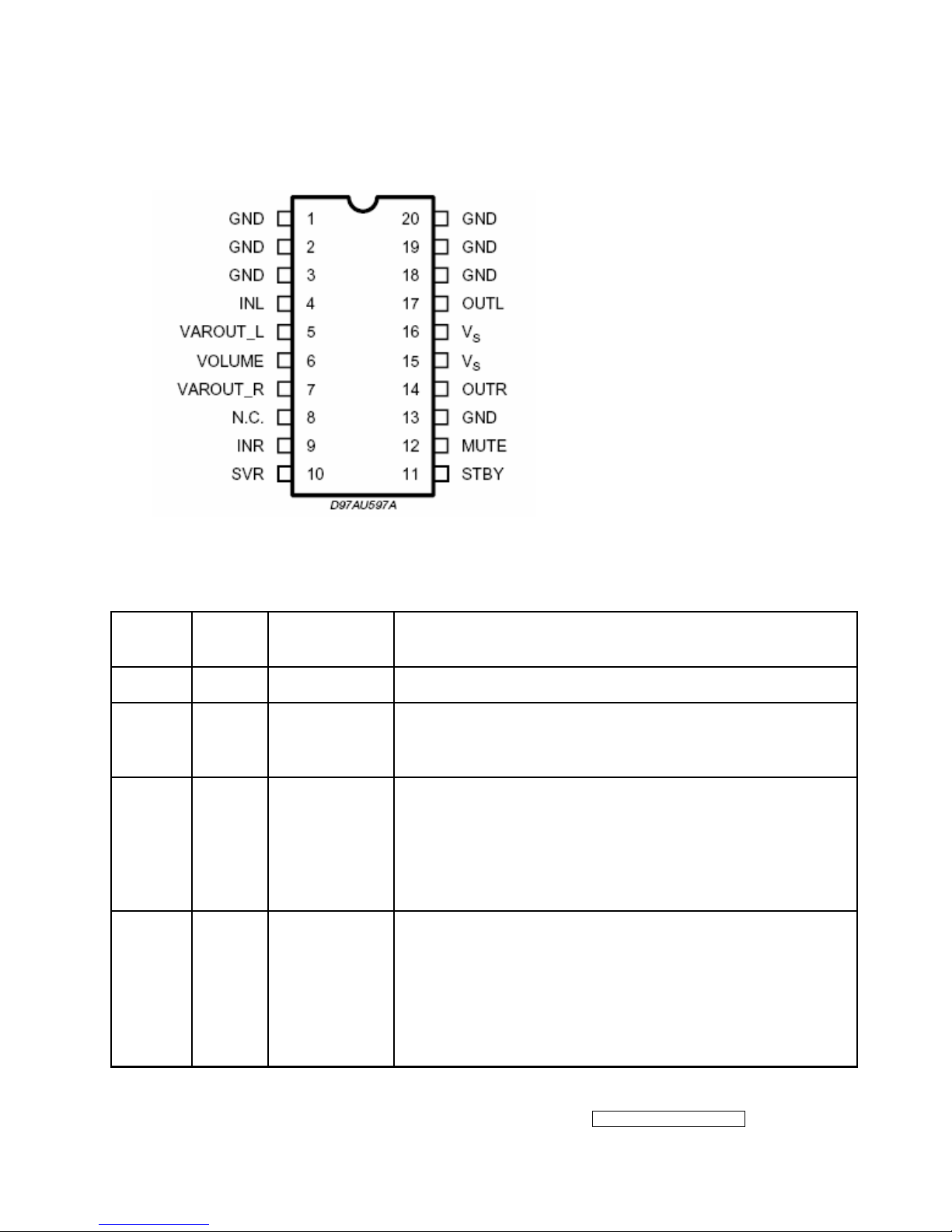
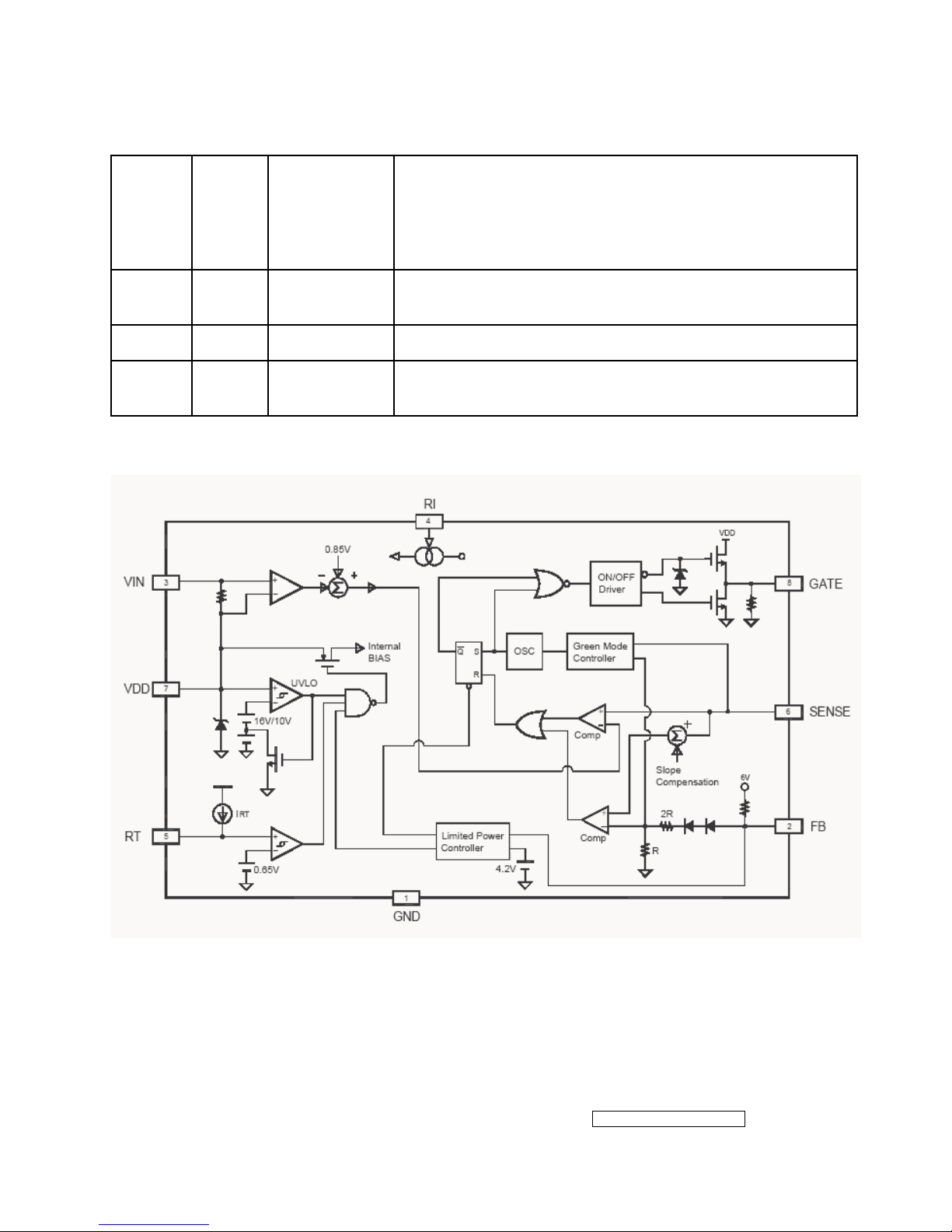
SG6841 (IC901): This highly integrated PWM controllers, Low start up current 30 uA. The
circuit unit has functions such as over-current protection, over-temperature protection,
over-voltage protection, output short-circuit protection and etc. The function of each pin
and the inside circuit diagram are as follows:
Pin/ No.
Pin
Name
Function Pin Description
1 GND Ground Ground.
2 FB Feedback
The signal from external compensation circuit is feed into
this pin. The PWM duty cycle is determined by this FB pin
and current sense signal from Pin 6.
3 VIN Start-Up
This pin is pulled high to the rectified line input through a
resistor for start-up. Since the start-up current requirement
for SG6841 is very small, a large start-up resistance can
be used to minimize power loss. Under normal operation,
this pin is also used to detect line voltage to compensate
for constant output power limit for universal AC input.
4 Ri
Reference
Setting
A resistor from RI pin to ground will generate a constant
current source for SG6841. This current is used to charge
an internal capacitor and hence the switching frequency
are determined. Increasing the resistance will decrease the
current source and reduce the switching frequency,. A 26k
Ω resistor R1 creates a 50uA constant current L1 and
generates 65kHz switching frequency.
- 24 –
ViewSonic Corporation
Confidential - Do Not Copy VX712
5 RT
Temperature
Protection
For over-temperature protection. An external NTC
thermistor is connected from this pin to ground. The
impedance of the NTC will decrease under high
temperature. Once the voltage on RT pin drops below a
fixed limit, the PWM output will be disabled.
6 SENSE Current Sense
Current sense. The sensed voltage is used for current
mode control and pulse-by-pulse current limiting.
7 VDD Power supply Power Supply.
8 GATE Driver Output
The totem-pole output driver for the power MOSFET. A soft
driving waveform is implemented to improve EMI.
Block Diagram
- 25 –
ViewSonic Corporation
Confidential - Do Not Copy VX712
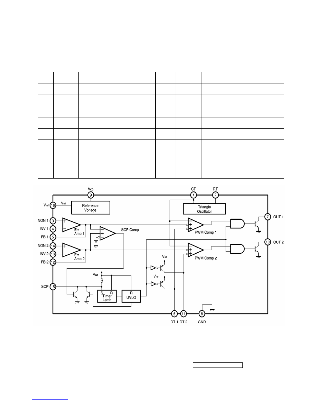
TL1451(U201): PWM control, voltage range for working: 3.6~35V, Has such functions as
short-voltage protection, Over-voltage protection, over-current protection and etc.
The function of each pin and the circuit diagram inside are as follows:
Pin Symbol Description Pin Symbol Description
1 CT
External timing capacitor
9 VCC
Power supply
2 RT
External timing resistor
10 2OUT
Output 2
3 1IN+
Positive input for error amplifier 1
11 2DTC
Output 2 dead time/soft start setting
4 1IN-
Positive input for error amplifier 2
12 2FBK
Error amplifier 2 output
5 1FBK
Error amplifier 1 output
13 2IN+
Positive input for error amplifier
6 1DTC
Output 1 dead time/soft start
setting
14 2IN-
Positive input for error amplifier
7 1OUT
Output 1
15 SCP
Timing latch setting
8 GND
Ground
16 REF
Reference voltage output (2.5v)

- 26 –
ViewSonic Corporation
Confidential - Do Not Copy VX712
5. Adjustment Procedure
5.1 ADJUSTMENT CONDITIONS AND PRECAUTIONS
1. Approximately 30 minutes should be allowed for warm up before proceeding.
2. Adjustments should be undertaken only on those necessary elements since most of them
have been carefully preset at the factory.
3. ESD protection is needed before adjustment.
5.2 MAIN ADJUSTMENTS
NO. FUNCTIONS DESIGNATION
1. White Balance Function Key
2. Geometry Function Key
5.3 ALIGNMENT PROCEDURES
Approximately 30 minutes should be allowed for warm up before proceeding
White-Balance adjustment.
1. Adjust of White Balance
1.)How to do the Chroma-7120 MEM .Channel setting
A、Reference to chroma 7120 user guide
B、Use “ SC” key and “ NEXT” key to modify xyY value and use “ID” key to modify the
TEXT description Following is the procedure to do white-balance adjust
2.)Setting the color temp. You want
A、MEM.CHANNEL9 ( 9300 color):
9300 color temp. parameter is Wx = 0.283 ±0.03;Wy = 0.298 ±0.03;
Y = 250 ±20 cd/m
2 ,
B、MEM.CHANNEL10 ( 6500 color):
6500 color temp. parameter is Wx = 0.313±0.03;Wy = 0.329 ±0.03;
Y = 260 ±20 cd/m
2,
C、MEM.CHANNEL 11 ( 5400 color):
5400 color temp. parameter is Wx = 0.335±0.03;Wy = 0.350 ±0.03;
Y = 250 ±20 cd/m
2,
D、MEM.CHANNEL10 ( SRGB color):
6500 color temp. parameter is Wx = 0.313±0.03;Wy = 0.329 ±0.03;
Y = 220 ±20 cd/m
2,
- 27 –
ViewSonic Corporation
Confidential - Do Not Copy VX712
3.)Into factory mode of VX712
A、First Power off, then press Switch 2 button along with press Power button will activate the
factory mode, then MCU will do AUTO LEVEL automatically. Meanwhile press MENU the
OSD screen will located at LEFT TOP OF PANEL.
4.)Bias adjustment :
Set the Contrast
to 70
Adjust the Brightness
to 100.
5.)Gain adjustment :
Move cursor to “-F-” and press MENU key
A、Adjust 9300 color-temperature
(1)、Switch the Chroma-7120 to RGB-Mode (with press “MODE” button )
(2)、Switch the MEM. channel to Channel 9 ( with up or down arrow on chroma 7120 )
(3)、The LCD-indicator on chroma 7120 will show x = 0.283 ±0.03, y =0.298 ±0.03, Y =
250 ±20 cd/m
2
(4)、Adjust the RED of color1 on factory window until chroma 7120 indicator reached the
value R=100
(5)、Adjust the GREEN of color1 on factory window until chroma 7120 indicator reached
the value G=100
(6)、Adjust the BLUE of color1 on factory window until chroma 7120 indicator reached the
value B=100
(7)、Repeat above procedure ( item 4,5,6) until chroma 7120 RGB value meet the
tolerance =100±5
B、Adjust 6500 color-temperature
(1)、Switch the chroma-7120 to RGB-Mode (with press “MODE” button )
(2)、Switch the MEM .channel to Channel 10( with up or down arrow on chroma 7120 )
(3)、The LCD-indicator on chroma 7120 will show x = 0.313 ±0.03, y = 0.329 ±0.03, Y =
260 ±20 cd/m
2
(4)、Adjust the RED of color3 on factory window until chroma 7120 indicator reached the
value R=100
(5)、Adjust the GREEN of color3 on factory window until chroma 7120 indicator reached
the value G=100
(6)、Adjust the BLUE of color3 on factory window until chroma 7120 indicator reached the
value B=100
(7)、Repeat above procedure ( item 4,5,6) until chroma 7120 RGB value meet the
tolerance =100±5
 Loading...