

Page 1

Service Manual
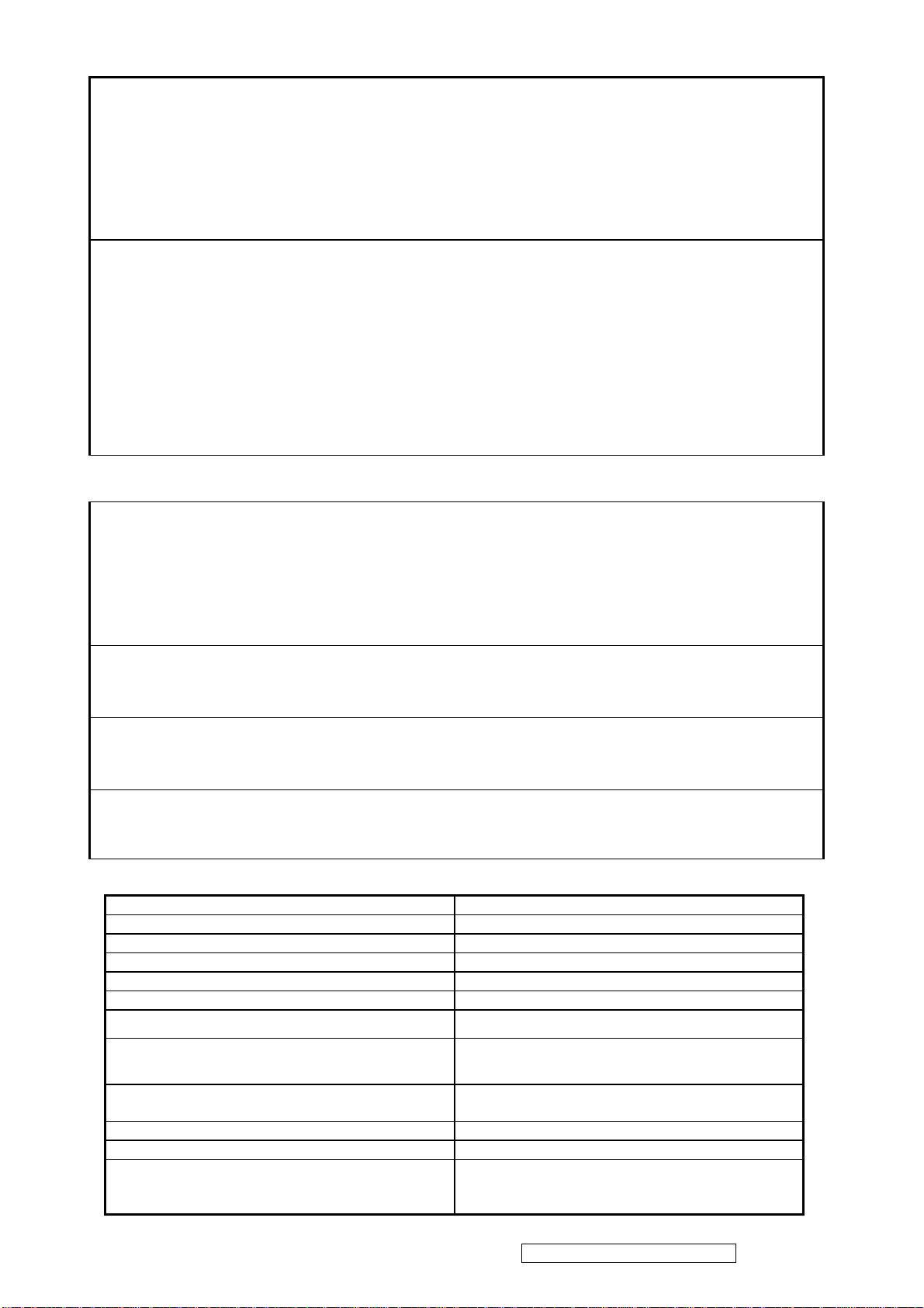
ViewSonic VA912-2
Model No. VS10696-2E
19” Color TFT LCD Display
(VA912-2 Rev. 1a Feb. 2006)
ViewSonic 381 Brea Canyon Road, Walnut, California 91789 USA - (800) 888-8583
Page 2
Copyright
Copyright © 2005 by ViewSonic Corporation.All rights reserved.No part of this publication may be reproduced,
transmitted, transcribed, stored in a retrieval system, or translated into any language or computer language, in
any form or by any means, electronic, mechanical, magnetic, optical, chemical, manual or otherwise, without
the prior written permission of ViewSonic Corporation.
Disclaimer
ViewSonic makes no representations or warranties, either expressed or implied, with respect to the contents
hereof and specifically disclaims any warranty of merchantability or fitness for any particular purpose. Further,
ViewSonic reserves the right to revise this publication and to make changes from time to time in the contents
hereof without obligation of ViewSonic to notify any person of such revision or changes.
Trademarks
Optiquest is aregistered trademark of ViewSonic Corporation.
ViewSonic is a registered trademark of ViewSonic Corporation.
All other trademarks used within this document are the property of their respective owners.
Revision History
Revision SM Editing Date ECR Number
1a 02/07/2006 Initial release Jamie Chang
Description of Changes Editor
ViewSonic Corporation Confidential - Do Not Copy VA912-2
i
Page 3

TABLE OF CONTENTS
1. Precautions and Safety Notices 1
2. Specification 4
3. Front Panel Function Control Description 10
4. Circuit Description 15
5. Adjustment Procedure 20
6. Troubleshooting Flow Chart 43
7. Recommended Spare Parts List 58
8. Exploded Diagram and Exploded Parts List 61
9. Block Diagram 62
10. Schematic Diagrams 63
11. PCB Layout Diagrams 84
ViewSonic Corporation Confidential - Do Not Copy VA912-2
ii
Page 4

1. Precautions and Safety Notices
1. Appropriate Operation
(1) Turn off the product before cleaning.
(2) Use only a dry soft cloth when cleaning the LCD panel surface.
(3) Use a soft cloth soaked with mild detergent to clean the display housing.
(4) Use only a high quality, safety approved AC/DC power cord.
(5) Disconnect the power plug from the AC outlet if the product will not be used for a long period of time.
(6) If smoke, abnormal noise, or strange odor is present, immediately switch the LCD display off.
(7) Do not touch the LCD panel surface with sharp or hard objects.
(8) Do not place heavy objects on the LCD display, video cable, or power cord.
(9) Do not use abrasive cleaners, waxes or solvents for your cleaning.
(10) Do not operate the product under the following conditions:
- Extremely hot, cold or humid environment.
- Areas containing excessive dust and dirt.
- Near any appliance generating a strong magnetic field.
- In direct sunlight.
2. Caution
No modification of any circuit should be attempted. Service work should only be performed after you are thoroughly
familiar with all of the following safety checks and servicing guidelines.
3. Safety Check
Care should be taken while servicing this LCD display. Because of the high voltage used in the inverter circuit, the voltage
is exposed in such areas as the associated transformer circuits.
4. LCD Module Handling Precautions
4.1 Handling Precautions
(1) Since front polarizer is easily damaged, pay attention not to scratch it.
(2) Be sure to turn off power supply when connecting or disconnecting input connector.
(3) Wipe off water drops immediately. Long contact with water may cause discoloration or spots.
(4) When the panel surface is soiled, wipe it with absorbent cotton or other soft cloth.
(5) Since the panel is made of glass, it may break or crack if dropped or bumped on hard surface.
(6) Since CMOS LSI is used in this module, take care of static electricity and ensure human earth when handling.
(7) Do not open or modify the Module Assembly.
(8) Do not press the reflector sheet at the back of the module in any direction.
(9) In the event that a Module must be put back into the packing container slot after it was taken out of the
container, do not press the center of the CCFL Reflector edge. Instead, press at the far ends of the
CFL Reflector edge softly. Otherwise the TFT Module may be damaged.
(10) At the insertion or removal of the Signal Interface Connector, be sure not to rotate or tilt the Interface
Connector of the TFT Module.
ViewSonic Corporation Confidential - Do Not Copy VA912-2
1
Page 5

(11) After installation of the TFT Module into an enclosure (LCD monitor housing, for example), do not twist or
bend the TFT Module even momentarily. When designing the enclosure, it should be taken into consideration
that no bending/twisting forces may be applied to the TFT Module from outside. Otherwise the TFT Module
may be damaged.
(12) The cold cathode fluorescent lamp in the LCD contains a small amount of mercury. Please follow local
ordinances or regulations for disposal.
(13) The LCD module contains a small amount of materials having no flammability grade. The LCD module
should be supplied with power that complies with the requirements of Limited Power Source
(IEC60950 or UL1950), or an exemption should be applied for.
(14) The LCD module is designed so that the CCFL in it is supplied by a Limited Current Circuit (IEC60950
or UL1950). Do not connect the CCFL to a Hazardous Voltage Circuit
ViewSonic Corporation Confidential - Do Not Copy VA912-2
2
Page 6
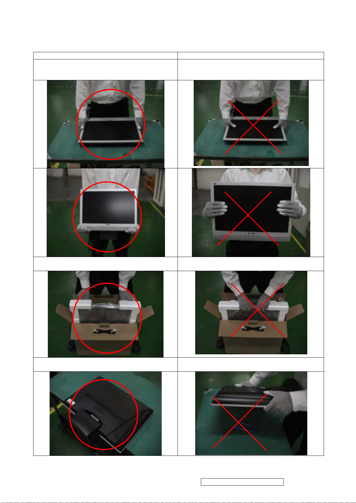
Handing and Placing methods
Correct methods : Incorrect Methods :
Only touch the metal-frame of the panel or the front
cover of the monitor.
Do not touch the surface of the polarizer .
Surface of the panel is pressed by fingers & this may
cause “ MURA “
Take out the monitor with cushion Take out the monitor by grasping the LCD panel.
That may cause “ MURA“.
Place the monitor on a clean & soft foam pad . Place the monitor on foreign objects .
That could scratch the surface of panel
ViewSonic Corporation Confidential - Do Not Copy VA912-2
3
Page 7

2. SPECIFICATION
2.1 INTRODUCTION
FEATURES VA912-2
Size 19”
Luminance (Typ, cd/㎡) 300 cd/㎡
Contrast Ratio (Typ) 800:1
TFTLCD PANEL
Input Signal
Sync Compatibility
Compatibility
Power Voltage AC 100-240V, 50/60Hz Yes
Power Consumption
Audio 1.5 W Yes
Ergonomics
OSD Control
Dimension
Weight
Operating Condition
Storage Condition
Regulation
Colors ( 6 bit + 2 bit FRC) 16.2 M colors
Response Time (Typ) 16 ms
Viewing Angle (H/V) 170 ° / 170 °
Recommend resolution 1280x1024@60Hz
Analog (75ohms, 0.7/1.0 Vp-p) Yes
Digital No
Separate Sync Yes
Composite Sync No
Sync on Green No
PC Yes
Power Mac Yes
TV Box (NextVision 6) Yes
On Mode(Max / Typ) 65W / 60W
Active Off Mode (Max)
Tilt ( 20 ° +-2° - -5 °+-1.5°) Yes
Swivel No
Pivot No
Height Adjust No
[; X] [ 1 ] [▼] [▲] [ 2 ] [
Physical (W x H x D mm) 424 x 442 x 186
Package (W x H x D mm) 480 x 524 x 228
Physical (Net kg/lb) 5.5kg/12.1lb
Package (Gross Kg/lb) 8.1kg/17.9lb
Temperature (℉/℃) 41℉-95℉/+5℃-+35℃
Humidity (%) 20 % - 80 %
Temperature (℉/℃) -4℉-131℉/-20℃-55℃
Humidity (%) 20 % - 85 %
UL, cUL, FCC-B, CB, CE, NOM, TUV/GS, TUV ERGO (covers ISO13406-2 &
MPRII), TCO99, GOST-R + 20 ORIGINAL COPIES HYGIENIC, SASO, PCBC,
VCCI, BSMI, CCC, (PSB), (C-TICK), TUV-S, Green Mark,
]
≦3 W
Ye s
2.2 GENERAL specification
Test Resolution & Frequency 1280x1024 @ 60Hz
Test Image Size Full Size
Contrast and Brightness Controls
ViewSonic Corporation Confidential - Do Not Copy VA912-2
Factory Default:
Contrast = 70%, Brightness = 100%
4
Page 8
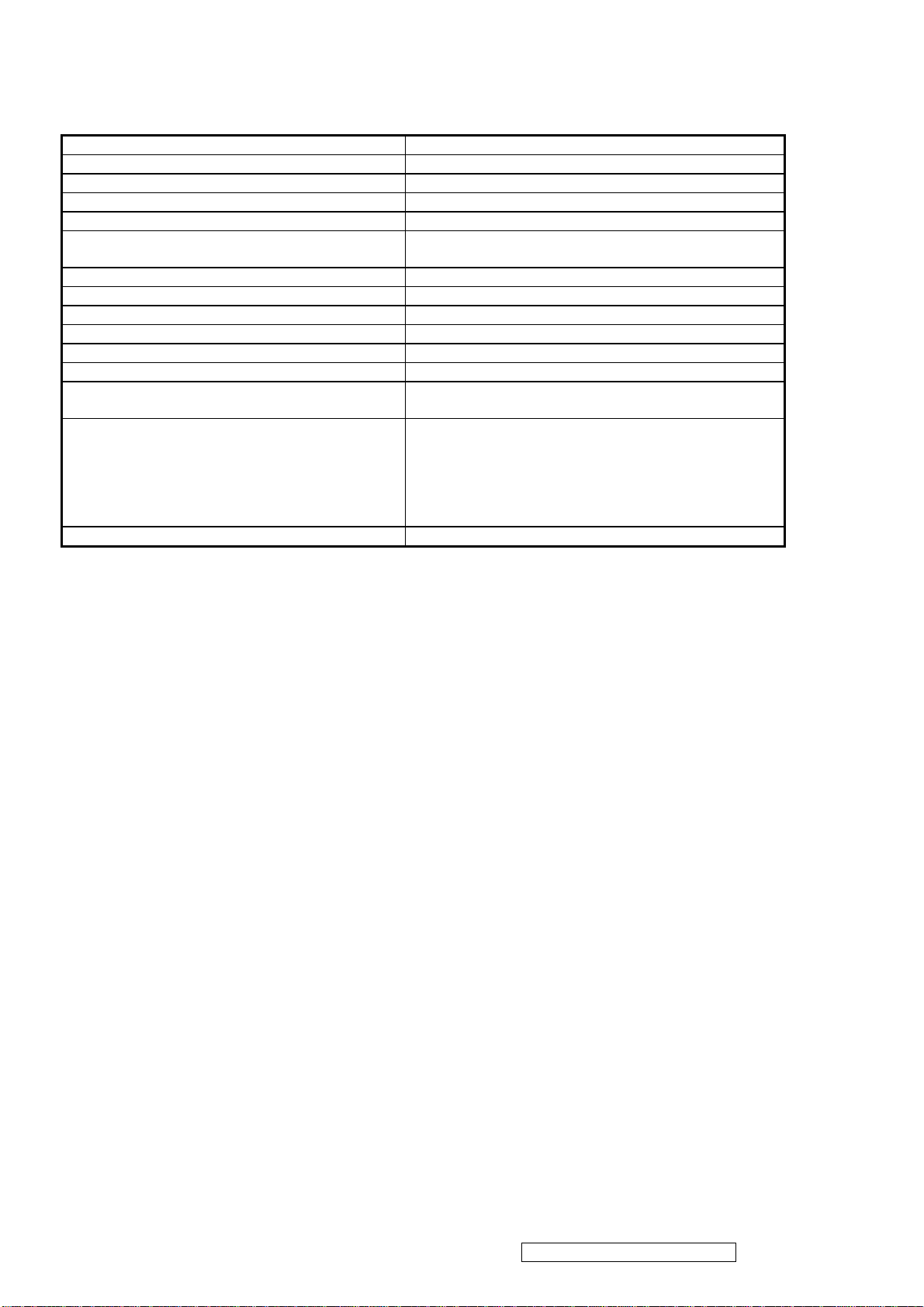
2.3 VIDEO INTERFACE
Analog Input Connector DB-15 (Analog), refer the appendix A
Digital Input Connector N/A
Default Input Connector Defaults to the first detected input
Video Cable Strain Relief Equal to twice the weight of the monitor for five minutes
Video Cable Connector DB-15 Pin out Compliant DDC 2B
Video Signals
1. Video RGB (Analog)
Separate
Video Impedance 75 Ohms (Analog)
Maximum PC Video Signal 950 mV with no damage to monitor
Maximum Mac Video Signal 1250 mV with no damage to monitor
Sync Signals TTL
DDC 2B Compliant with Revision 1.3
Sync Compatibility Separate Sync
Video Compatibility
Shall be compatible with all PC type computers,
Macintosh computers, and after market video cards
640 x 350*, 640 x 480, 720 x 400* (640 x 400*), 800 x
600, 832 x 624, 1024 x 768, 1152 x 870, 1280 x 720,
Resolution Compatibility
1280 x 960, 1280 x 1024
* The image vertical size might not be full screen.
But the image vertical position should be at the center.
Exclusions Not compatible with interlaced video
ViewSonic Corporation Confidential - Do Not Copy VA912-2
5
Page 9

2.5 ELECTRICAL REQUIREMENT
Horizontal / Vertical Frequency
Horizontal Frequency 30 – 82 KHZ
Vertical Refresh Rate 50 – 85* HZ.
Maximum Pixel Clock 135 MHz (EDID data is 140MHz)
Sync Polarity Independent of sync polarity.
Timing Table
Item Timing Analog
1 640 x 350 @ 70Hz, 31.5kHz Yes
2 640 x 400 @ 60Hz, 31.5kHz Yes
3 640 x 400 @ 70Hz, 31.5kHz Yes
4 640 x 480 @ 60Hz, 31.5kHz Yes
5 640 x 480 @ 67Hz, 35.0kHz Yes
6 640 x 480 @ 72Hz, 37.9kHz Yes
7 640 x 480 @ 75Hz, 37.5kHz Yes
8 640 x 480 @ 85Hz, 43.27kHz Yes
9 720 x 400 @ 70Hz, 31.5kHz Yes
10 800 x 600 @ 56Hz, 35.1kHz Yes
11 800 x 600 @ 60Hz, 37.9kHz Yes
12 800 x 600 @ 75Hz, 46.9kHz Yes
13 800 x 600 @ 72Hz, 48.1kHz Yes
14 800 x 600 @ 85Hz, 53.7kHz Yes
15 832 x 624 @ 75Hz, 49.7kHz Yes
16 1024 x 768 @ 60Hz, 48.4kHz Yes
17 1024 x 768 @ 70Hz, 56.5kHz Yes
18 1024 x 768 @ 72Hz, 58.1kHz Yes
19 1024 x 768 @ 75Hz, 60.0kHz Yes
20 1024 x 768 @ 85Hz, 68.67kHz Yes
21 1152 x 870 @ 75Hz, 68.7kHz Yes
22 1280 x 1024 @ 60Hz, 63.4kHz Yes
23 1280 x 1024 @ 75Hz, 79.97kHz Yes
24 1280x 720 @ 60Hz, 45kHz (HDTV) Yes
Note 1:When Vertical frequency at 85Hz or resolution, the vertical image size might not be full screen. But the
vertical image position should be at the center.
Primary Presets
1280x1024 @ 60Hz
User Presets
Number of User Presets (recognized timings) Available: 10 presets total in FIFO configuration
Changing Modes
● Maximum Mode Change Blank Time for image stability : 3 seconds (Max), excluding “Auto Adjust” time
● Under DOS mode (640 x 350, 720 x 400 & 640 x 400), there is no “Auto Adjust” feature.
● The monitor needs to do “Auto Adjust” the first time a new mode is detected but except the DOS mode 640 x 350, 720 x
400 & 640 x 400.(see section “0-Touch™ Function Actions”)
● While running Change Mode, Auto Adjust or Memory Recall, the image shall blank
ViewSonic Corporation Confidential - Do Not Copy VA912-2
7
Page 10
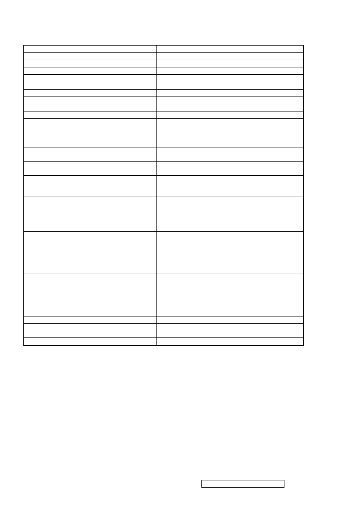
2.4 POWER SUPPLY
Power Supply (Adapter) Part Number: UP065B1190 or ADP-65MB
Input Voltage Range 90 TO 264 VAC
Input Frequency Range 47 TO 63 HERTZ
Short Circuit Protection Output can be shorted without damage
Over Current Protection 5.13 A typical at 18.1 VDC
Leakage Current 0.25mA (Max) at 264VAC / 50Hz
EFFICIENCY 80 % typical at 115VAC Full Load
Fuse Internal and not user replaceable
Power Dissipation 65 Watts
Max Input AC Current 1.8Arms @ 90VAC,
INRUSH CURRENT (COLD START) 100 A @ 240VAC , 50Hz
Shall start and function properly when under full load,
Power Supply Cold Start
with all combinations of input voltage, input frequency,
and operating temperature
Power Supply Transient Immunity
Power Supply Line Surge Immunity
Shall be able to withstand an EN61000-4-4 ±2KV
transient test with no damage
Shall be able to withstand ±2KV (L-L) and ±2.3KV
(L-PE) with no damage
Shall be able to function properly, without reset or visible
Power Supply Missing Cycle Immunity
screen artifacts, when ½ cycle of AC power is randomly
missing at nominal input
The power supply shall not produce audible noise that
would be detectable by the user. Audible shall defined
Power Supply Acoustics
to be in compliance with ISO 7779 (DIN EN27779:1991)
Noise measurements of machines acoustics. Power
Switch noise shall not be considered
Separate 3-prong NEMA 5-15P type plug. Length =
US Type Power Cable
1.8m. Connects to display.
Color = Black
Schuko CEE7-7 type plug.
European Type Power Cable
Length = 1.8m, Connects to display.
Color = Black
Separate 3-prong type plug.
CCC Type Power Cable
Length = 1.8m. Connects to display.
Color = Black
Separate 2-prong NEMA 1-15P type plug. Length =
PSE Type Power Cable
1.8m. Connects to display.
Color = Black
Power Saving Operation(Method) VESA DPMS Signaling
Power Consumption
ON Mode < 65 W (max) / 60W (typ)
ACTIVE OFF < 3W
Recovery Time ON MODE = N/A, ACTIVE OFF < 5 SEC
ViewSonic Corporation Confidential - Do Not Copy VA912-2
6
Page 11

2.6 FRONT PANEL CONTROLS AND INDICATORS
Front Panel Hardware Controls
Power Switch (Front Head) Power Control, soft Power Switch.
Power LED (Front Head) Green – ON
Orange – Active Off
Dark = Soft Power Switch OFF
Front Panel Controls (Head)
[;X] [ 1 ] [▲] [▼] [ 2 ] [
]
] Power
[
[ 1 ] Button 1
[ 2 ] Button 2
[▲] Up arrow button
[▼] Down arrow button
[; X] MUTE
Note: Power Button, Button 1 and Button 2 and Mute
Button must be one-shot logic operation. (i.e. there should
be no cycling)
Reaction Time OSD must fully appear within 0.5s after pushing Button 1
Short Cuts Function from the button(s)
[1] Main Menu
[2] Input toggle (Analog or Digital) or Auto Image Adjust.
[▼] or [▲] To immediately activate Contrast menu. It should be change to Brightness
OSD by push button [2]
[▼] + [▲] Recall both of Contrast and Brightness to default
[1] + [2] Toggle 720x400 and 640x400 mode when input 720x400 or 640x400
mode
[1] + [▼] + [▲] White Balance. (Not shown on user’s guide)
[1] + [▼] Power Lock
[1] + [▲] OSD Lock
Remark : All the short cuts function are only available while OSD off
Main Menu Controls
Auto Image Adjust*
Contrast/Brightness*
Audio Adjust
Vo l u m e *
4
, Mute*4
1
2*4
Color Adjust
sRGB, 9300K, 6500K(default), 5400, 5000, User Color [R, G, B]
Information [H Frequency, V Frequency, Resolution, Pixel Clock, Serial Number,
Model Number, “www.ViewSonic.com
Manual Image Adjust [H. Size*
1
, H./V. Position*1, Fine Tune*1, Sharpness*3]
” ]
Setup Menu
Language [English, French, German, Spanish, Italian, Finnish, Japanese, Traditional Chinese, Simplified
Chinese], Resolution Notice, OSD Position, OSD Timeout, OSD Background
MEMORY RECALL
1
*
These functions are not available in Digital Mode
2
*
These functions are not available under sRGB Mode
3
*
These functions are not available under Native Resolution Mode
4
*
These functions setting can be recalled to default by [▼]+[▲]
[Remark] Please refer to the detail in the Appendix C
ViewSonic Corporation Confidential - Do Not Copy VA912-2
8
Page 12
Function descriptions
OSD Lock short cuts function for the buttons
The OSD lock will be activated by pressing the front panel control buttons "(1), & (▲)" for 10 seconds. If the user
then tries to access the OSD by pressing any of the buttons "1", "▼", "▲", "2" a message will appear on the screen
for 3 seconds showing "OSD Locked". The OSD lock will be deactivated by pressing the front panel control
buttons "(1), & (▲)" again for 10 seconds.
Note1: When the OSD is locked will lock all functions, including “Volume” and “Mute”
Note 2: Status bar indicating OSD Lock or Unlock is in progress and when complete it will indicate “OSD
Locked”
Note 3: OSD Lock should not lock Power Button and Power Lock function
Power Lock short cuts function for the buttons
The power button lock will be activated by pressing the front panel control buttons "(1), & (▼)" for 10 seconds.
Locking the power button means that the user won't be able to turn off the LCD while the power button is locked.
If the user presses the power button while it is locked, a message will appear on the screen for 3 seconds showing
"Power Button Locked". It also means that with the power button locked, the LCD would automatically turn back
"On" when power is restored after a power failure. If the power button is not in the locked mode, then power
should return to it's previous state when power is restored after a power failure. The power button lock will be
deactivated by pressing the front panel control buttons "(1), & (▼)" again for 10 seconds.
Note 1: Status bar indicating Power Button lock or unlock is in progress and when complete it will indicate
“Power Button Locked”
Note 2: Power should only be lockable in the “On State”
Memory Recall Actions
Memory Recall action on the analog and digital mode as below
1. Recall white balance to factory setting
2. Set the factory defaults as shown in Section 4-8
3. Clean all the mode setting buffer
4. Execute Auto Image Adjust
Note: Memory Recall should have no effect for Language, Power Lock, User Color Settings or Input Priority
Resolution Notice Ac tions
1. Resolution Notice OSD should show on screen after changing to non-native mode for 30 sec
2. The OSD should disappear after 10 sec or by pushing button [1] or [2]
Resolution Notice function should be disabled when push button [2] under Resolution Notice OSD
0-Touch™ Function Actions
1. Execute Auto Image Adjust when new mode detected, and save the settings to buffer for further use
2. It should be reset by Memory Recall function
(Should not reset by power off, power unplug and others)
OSD Auto Save
The OSD shall save new settings when it is turned off by the user or when it times out. There shall not be a
separate save
2
.7 AUDIO INTERFACE (SPEAKER SPECIFICATION)
Line input connection 3.5 mm stereo jack
Line input signal 1.0 Vrms
Line input impedance 10 kOhm
Maximum power output (Electric) 1.5 W @ < 8% distortion
Signal to Noise Ratio 72 dB
Frequency response 500 Hz – 20 Khz
Distortion
Vibration
Screen image
Connector PC99 requirement Audio in Lime Green pantone # 577C
Cable type / length 3.5mm stereo cable / 1.8m length
Audio DPMS
< 8 % THD (@1kHz)
There should be no audible vibration with volume at
100%. (Input signal within 1 Vrms)
There should be no affect on the screen image
stability under any conditions
Note: There is no guarantee <1 W power
consumption in Active Off mode, when the Audio
Cable is connected
ViewSonic Corporation Confidential - Do Not Copy VA912-2
9
Page 13
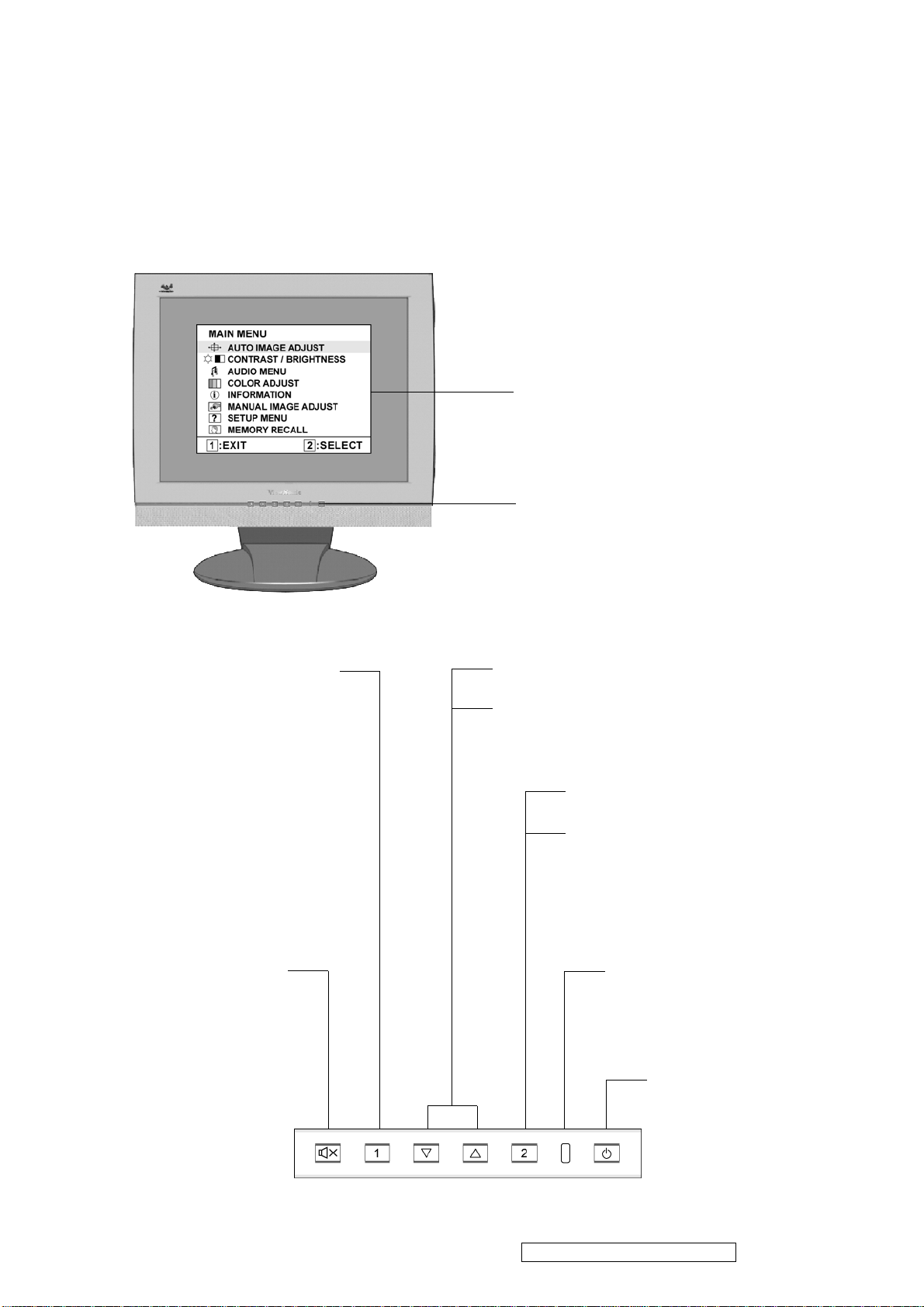
3.Front Panel Function Control Description
Adjusting the Screen Image
Use the buttons on the front control panel to display and adjust the OnView® controls which
display on the screen. The OnView controls are explained at the top of the next page and are
defined in “Main Menu Controls” .
Main Menu
with OnView controls
Front Control Panel
shown below in detail
Displays the Main Menu or
exits the control screen and
saves adjustments.
Audio Mute
button turns
the sound off
Scrolls through menu options and
adjusts the displayed control.
Also a shortcut to display the Contrast
adjustment control screen.
Displays the control screen
for the highlighted control.
Also toggles between two
controls on some screens.
Power light
Green = ON
Orange = Power Saving
Standby Power
On/Off
ViewSonic Corporation Confidential - Do Not Copy VA912-2
10
Page 14

Do the following to adjust the screen image:
1. To display the Main Menu, press button [1].
NOTE: All OnView menus and adjustment screens disappear automatically after about 15
seconds. This is adjustable through the OSD timeout setting in the setup menu.
2. To select a control you want to adjust, press S or T to scroll up or down the Main Menu.
3. After the control is selected, press button [2]. A control screen like the one shown below
appears.
The command line at the bottom of the
control screen tells what to do next from
this screen. You can toggle between control
screens, adjust the selected option, or exit
the screen.
4. To adjust the control, press the up S or down T buttons.
5. To save the adjustments and exit the menu, press button [1] twice.
The following tips may help you optimize your display:
• Adjust your computer's graphic card so that it outputs a video signal 1280 x 1024 @ 60Hz
to the LCD display. (Look for instructions on “changing the refresh rate” in your graphic
card's user guide.)
• If necessary, make small adjustments using H. POSITION and V. POSITION until the
screen image is completely visible. (The black border around the edge of the screen should
barely touch the illuminated “active area” of the LCD display.)
ViewSonic Corporation Confidential - Do Not Copy VA912-2
11
Page 15
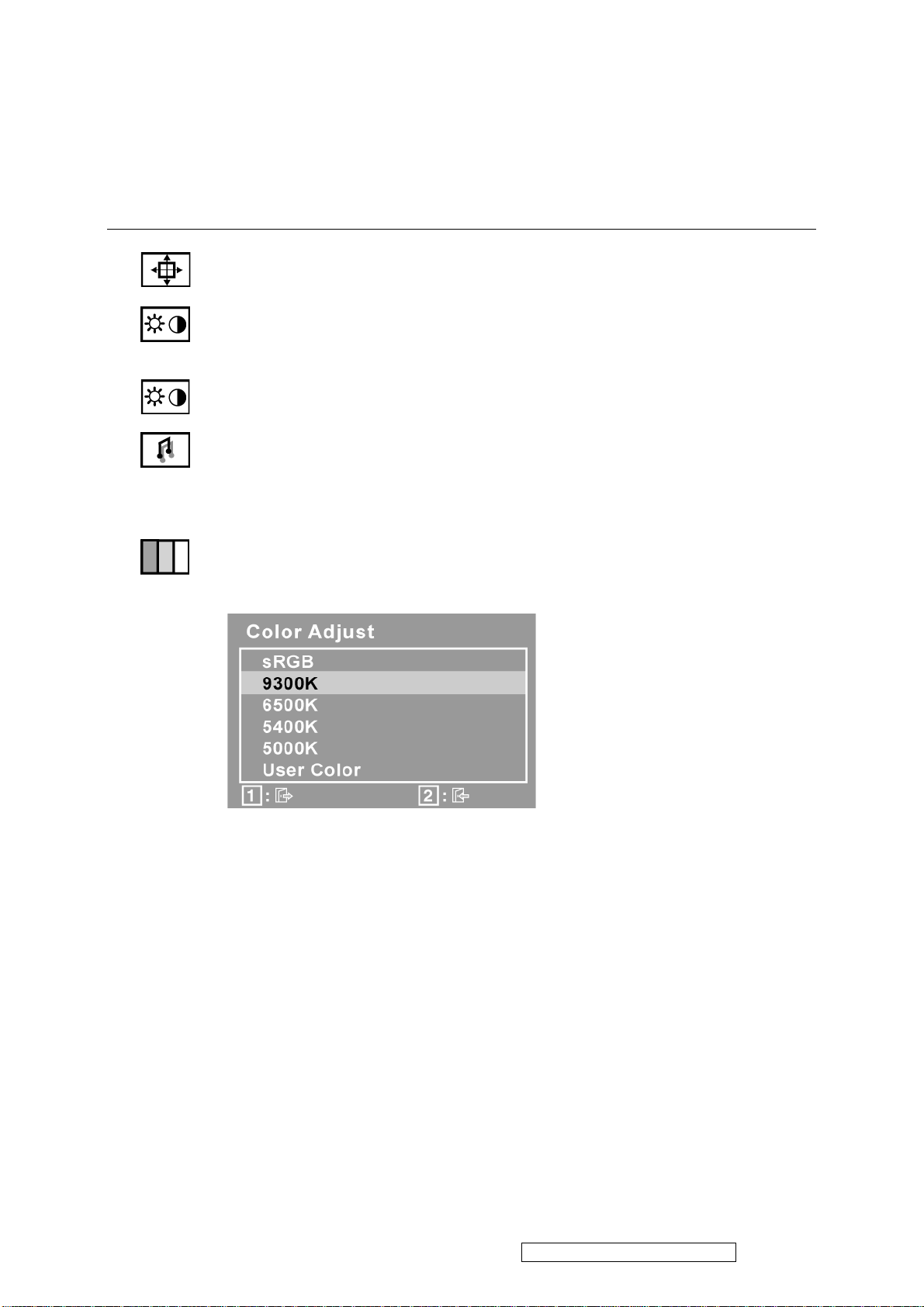
Main Menu Controls
Adjust the menu items shown below by using the up S and down T buttons.
Control Explanation
Auto Image Adjust sizes and centers the screen image automatically.
Contrast adjusts the difference between the image background (black level)
and the foreground (white level).
Brightness adjusts background black level of the screen image.
Audio Adjust
Vol ume increases the volume, decreases the volume, and mutes the audio.
Mute temporarily silences audio output.
Color Adjust provides several color adjustment modes: preset color
temperatures and RGB which allows you to adjust red (R), green (G), and blue
(B) separately. The factory setting for this product is 6500K (6500 Kelvin).
9300K-Adds blue to the screen image for cooler white (used in most office
settings with fluorescent lighting).
6500K-Adds red to the screen image for warmer white and richer red.
5400K-Adds green to the screen image for a darker color.
5000K-Adds blue and green to the screen image for a darker color.
User Color Individual adjustments for red (R), green (G), and blue (B).
1. To select color (R, G or B) press button [2].
2. To adjust selected color, pressSandT.
Important: If you select RECALL from the Main Menu when the product is set
to a Preset Timing Mode, colors return to the 6500K factory preset.
ViewSonic Corporation Confidential - Do Not Copy VA912-2
12
Page 16
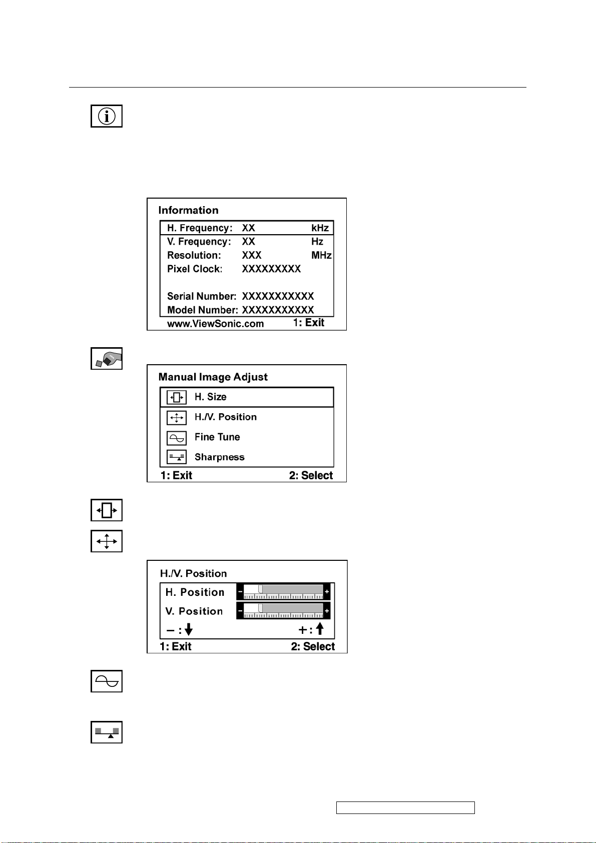
Control Explanation
Information displays the timing mode (video signal input) coming from the
graphics card in your computer, the LCD model number, the serial number, and
the ViewSonic website URL. See your graphic cards user guide for instructions
on changing the resolution and refresh rate (vertical frequency).
NOTE: VESA 1280 x 1024 @ 60Hz (recommended) means that the resolution
is 1280 x 1024 and the refresh rate is 60 Hertz.
Manual Image Adjust Sub-menu
H. Size (Horizontal Size) adjusts the width of the screen image.
H./V. Position (Horizontal/Vertical Position) moves the screen image left or
right and up or down.
Fine Tune sharpens the focus by aligning the text and/or graphic characters.
NOTE: Try Auto Image Adjust first.
Sharpness adjusts the clarity and focus of the screen image.
ViewSonic Corporation Confidential - Do Not Copy VA912-2
13
Page 17
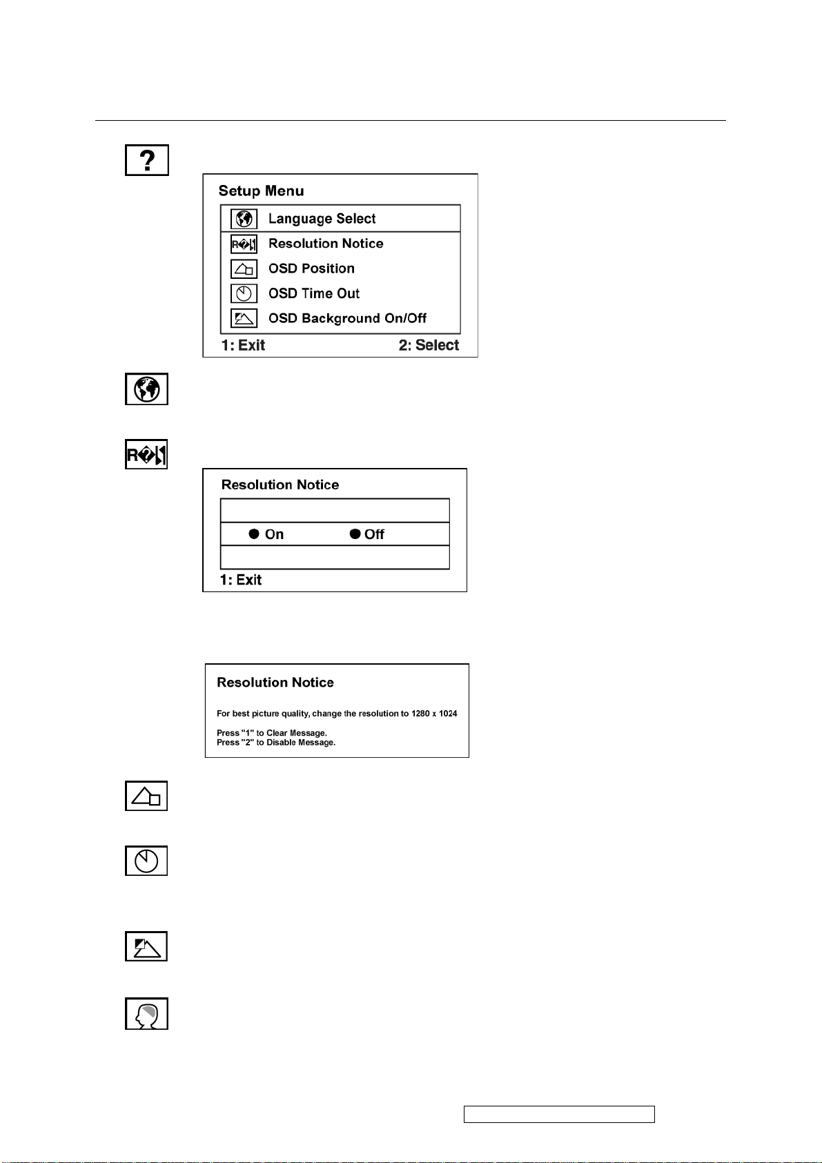
Control Explanation
Setup menu displays the menu shown below:
Language allows you to choose the language used in the menus and control
screens.
Resolution Notice allows you to enable or disable this notice.
If you enable the Resolution Notice shown above and your computer is set at a
resolution other than 1280 x 1024, the following screen appears.
OSD Position allows you to move the on-screen display menus and control
screens.
OSD Timeout sets the length of time the on-screen display screen is displayed.
For example, with a “30 second” setting, if a control is not pushed within 30
seconds, the display screen disappears.
OSD Background On/Off allows you to turn the On-Screen Display
background On or Off.
Memory Recall returns the adjustments back to factory settings if the display is
operating in a factory Preset Timing Mode listed in the Specifications of this
manual.
ViewSonic Corporation Confidential - Do Not Copy VA912-2
14
Page 18

4. Circuit Description
1. Power supply (DC/DC Converter)
The AT1741 is 2-channel PWM switching regulator controllers that contains an
on-chip 2.5V reference, two error amplifier, an adjustable oscillator, two
dead-time comparators, under voltage lockout circuitry and 2 common-emitter
output. It is idea for step-up, step-down, and inverting converter.
ViewSonic Corporation Confidential - Do Not Copy VA912-2
15
Page 19

2. Flash Memory
The F29C51001T/F29C51001B is a 1 Megabit, 5.0 Volt-only Flash Memory organized as 131,072
bytes of 8 bits each. This device is designed to use a 4.7 Volt to 5.3 Volt power supply to perform
in-system programming.
The 1 Megabit memory array is divided into thi rt y -t wo uniform blocks of 4 Kbytes each for data and/or
code storage.
The block architecture allows users to flexibly make chip erase or block erase operation. The block
erase feature allows a particular block to be erased and reprogrammed without affecting the data in
other blocks. After the device performs chip erase or block erase operatio n , it can be re pr og rammed on
a byte-by-byte basis.
ViewSonic Corporation Confidential - Do Not Copy VA912-2
16
Page 20
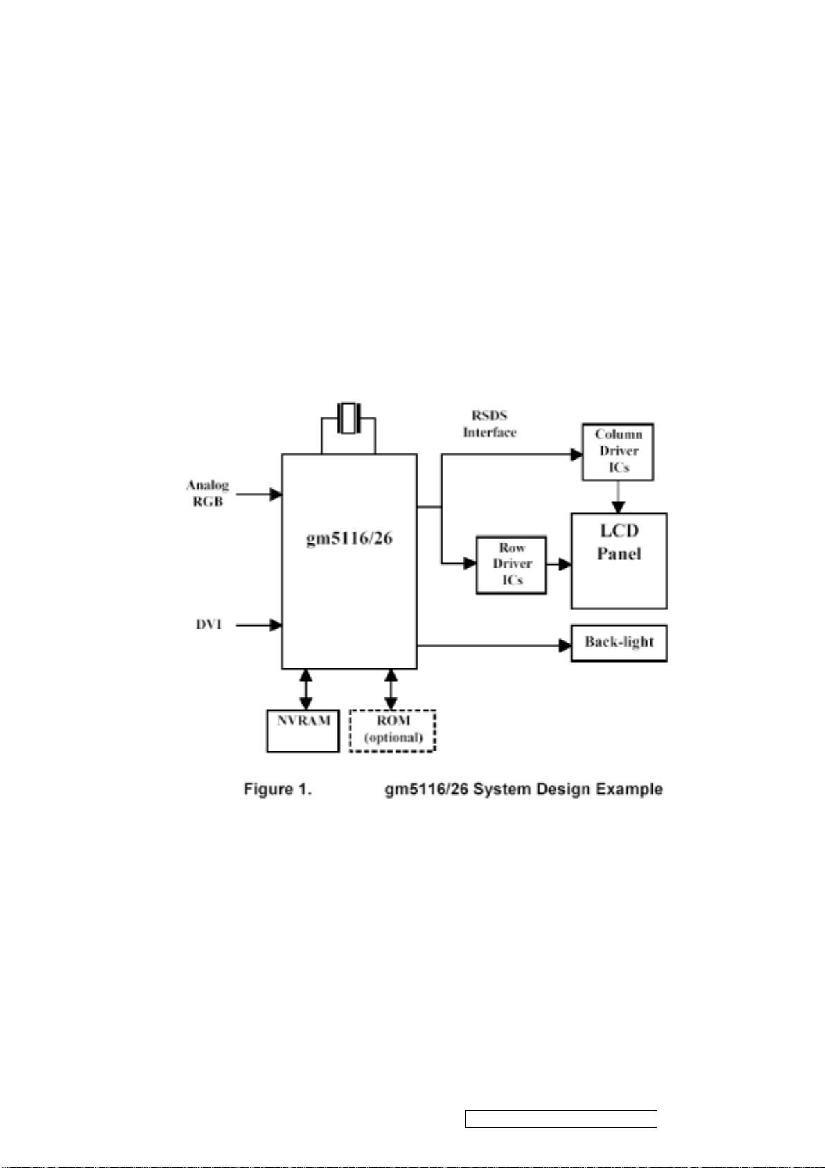
3. GM5120
The gm5116/26 is a graphic processing IC for Liquid Crystal Display (LCD) monitors at XGA/SXGA
resolution. It provides all key IC functions required for the highest quality LCD monitors. On-chip
functions include a high-speed triple-ADC and PLL, Ultra-Reliable DVI
TM
receiver, a high quality
zoom and shrink scaling engine, an on-screen display (OSD) controller, digital color controls and an
on-chip microcontroller (OCM). With this level of integration, the gm5116/26 devices simplify and
reduce the cost of LCD monitors while maintaining a high-degree of flexibility and quality.
ViewSonic Corporation Confidential - Do Not Copy VA912-2
17
Page 21

4. LVDS (THC63LVDM83A)
The THC63LVDM83A transmitter converts 28 bits of CMOS/TTL data into LVDS (Low Voltage
Differential Signaling) data stream. A phase-locked transmit clock is transmitted in parallel with the
data streams over a fifth LVDS link. The HC63LVDM83A can be programmed for rising edge or
falling edge clocks through a dedicated pin. The THC63LVDF84A receiver converts the LVDS data
streams back into 28 bits of CMOS/TTL data with falling edge clock. At a transmit clock frequency of
85MHz, 24 bits of RGB data and 4 bits of LCD timing and control data (HSYNC, VSYNC, CNTL1,
CNTL2) are transmitted at a rate of 595 Mbps per LVDS data channel.
ViewSonic Corporation Confidential - Do Not Copy VA912-2
18
Page 22

5. Micro Controller
The MTV312M micro-controller is an 8051 CPU core embedded device especially tailored for
CRT/LCD Monitor applications. It includes an 8051 CPU core, 1024-byte SRAM, 14 built-in PWM
DACs , VESA DCC interface, 4 -channel A/D converter , and a 64K-byte internal program
FLASH-ROM.
6. TSU57AK
The TSU57AK is a high performance, and fully integrated graphics process IC solution for LCD
m onitors with resolution up to SXGA. It is configured with an integrated triple-ADC/PLL, a high
quality scaling engine, an on-screen display controller, a built-in output clock generator, a panel timing
controller (TCON), an integrated DVI receiver, and RSDS display interface. To further reduce system
costs, the TSU57AK also integrates intelligent power management control capability for green-mode
requirements and spread-spectrum support for EMI management.
ViewSonic Corporation Confidential - Do Not Copy VA912-2
19
Page 23

5. Adjusting Procedure
A. Function Test and Alignment Procedure
1. All Modes Reset
You should do “All Model Reset” (Refer to Chap 3. Hot Keys for Function Controls) first.
This action will allow you to erase all end-user’s settings and restore the factory defaults.
2. Auto Image Adjust
The Auto Adjust is aimed to offer a best screen quality by built-in ASIC. For optimum
screen quality, the user has to adjust each function manually.
A.Turn the computer and LCD monitor on.
B. Press the ‘Auto’ button on monitor keypad to Auto Adjust.
C. The LCD monitor will start the Auto Adjust process automatically and run for 10
consecutive seconds, during which time you will notice the image change.
3. Firmware
Test Patten: Burn in Model (Refer to Chap3. Hot Keys for Function Control)
-Make sure the F/W is the latest version.
4. DCC
Test Patten: EDID program
-Make sure it can pass test program.
5. Window Shut Down
Test Signal: 1280*1024@60Hz
Test Pattern:
Checkered Pattern Every One Pixel (50%Green & 50%Blue)
Inspection Item: Flicker, Mura
6. Window BG
Test Signal: 1280*1024@60Hz
Test Pattern:
Window standard pattern
Inspection Item: Line Defect, Function Defect & Mura
ViewSonic Corporation Confidential - Do Not Copy VA912-2
20
Page 24
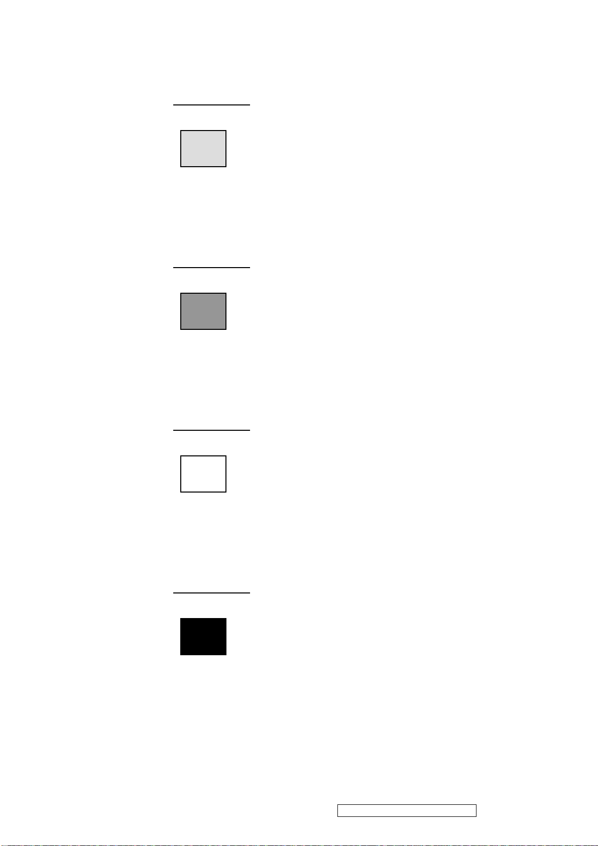
7. 25 Gray
8. 50 Gray
Test Signal: 1280*1024@60Hz
Test Pattern:
Full Screen 25% White (Gray)
Inspection Item: Particle, Line Defect & Mura
Test Signal: 1280*1024@60Hz
Test Pattern:
Full Screen 50% White (Gray)
Inspection Item: Bright Dot, Particle, Line Defect & Mura
9. White Box
Test Signal: 1280*1024@60Hz
Test Pattern:
Window standard pattern
Inspection Item: Particle, Line Defect, Power, Image Remain & Mura
10. Black Box
Test Signal: 1280*1024@60Hz
Test Pattern:
Window standard pattern
Inspection Item: Bright Dot, Line Defect & Power
ViewSonic Corporation Confidential - Do Not Copy VA912-2
21
Page 25
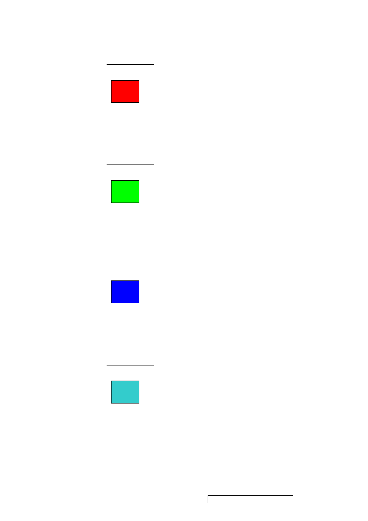
11. RED
Test Signal: 1280*1024@60Hz
Test Pattern:
Full Screen Red
Inspection Item: Bright Dot, Partial & Line Defect
12. Green
Test Signal: 1280*1024@60Hz
Test Pattern:
Full Screen Green
Inspection Item: Bright Dot, Partial & Line Defect
13. Blue
Test Signal: 1280*1024@60Hz
Test Pattern:
Full Screen Green
Inspection Item: Bright Dot, Partial & Line Defect
14. Gray_Scale_0-100_V64
Test Signal: 1280*1024@60Hz
Test Pattern:
Vertical 64 (256) Gray Scale (Right → Left,From 0 to 100% White)
Inspection Item: Line Defect & Function Defect
ViewSonic Corporation Confidential - Do Not Copy VA912-2
22
Page 26
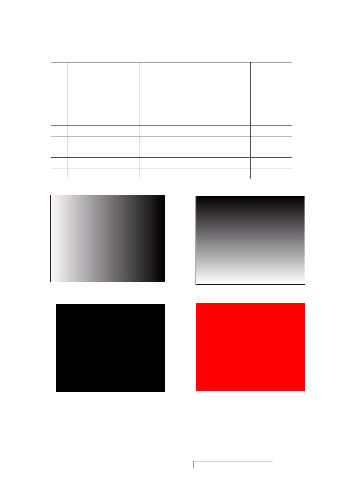
15. Function Test Display pattern
Item Pattern Description Remark
1
2
3
4
5
6
7
8
Gray_Scale_0-100_V
Gray_Scale_0-100_H
Black Full Screen Black Figure 3
Red Full Screen 50% Red Figure 4
Green Full Screen 50% Green Figure 5
Blue Full Screen 50% Blue Figure6
White Full Screen White Figure7
Black_Tile Black Tile Under White Background Figure 8
Vertical 64 (256) Gray Scale (右→左,From 0
Figure 1
to 100% White)
Horizontal 64 (256) Gray Scale (上→下,From
Figure 2
0 to 100% White)
Figure 1 Figure 2
Figure 4 Figure 3
ViewSonic Corporation Confidential - Do Not Copy VA912-2
23
Page 27

Figure 5
Figure 6 Figure 5
Figure 8 Figure 7
ViewSonic Corporation Confidential - Do Not Copy VA912-2
24
Page 28
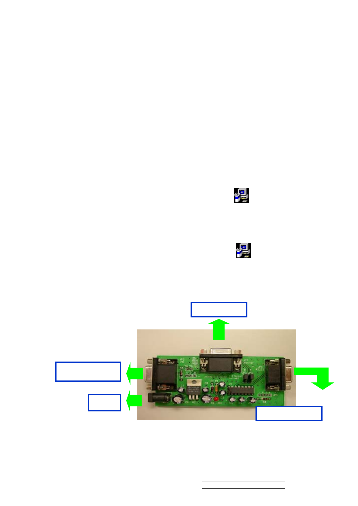
5.B. BIOS update procedure
I. For ViewSonic
BIOS Update User Guide
BIOS Update Flow for Genesis
1.1 Program:
1. 1. 1. Software
a. Please download the file “ Genesis” from CMO E-Sir system. There are ISP & BIOS two
files, kindly see as below.
a) ISPACK.EXE: Main program
b) Ancillary .ISPACK.EXE :Description program
1.1. 2.Hardware
•RS232 cable(9 Pin)
•D_Sub cable(15Pin)
GProbe4.2.0.3.exe
GProbe4.2.0.3_gm5126.exe
•12V Power supply
•RS232 to D_Sub transfer BD
PC optional
12V
ViewSonic Corporation Confidential - Do Not Copy VA912-2
25
Page 29
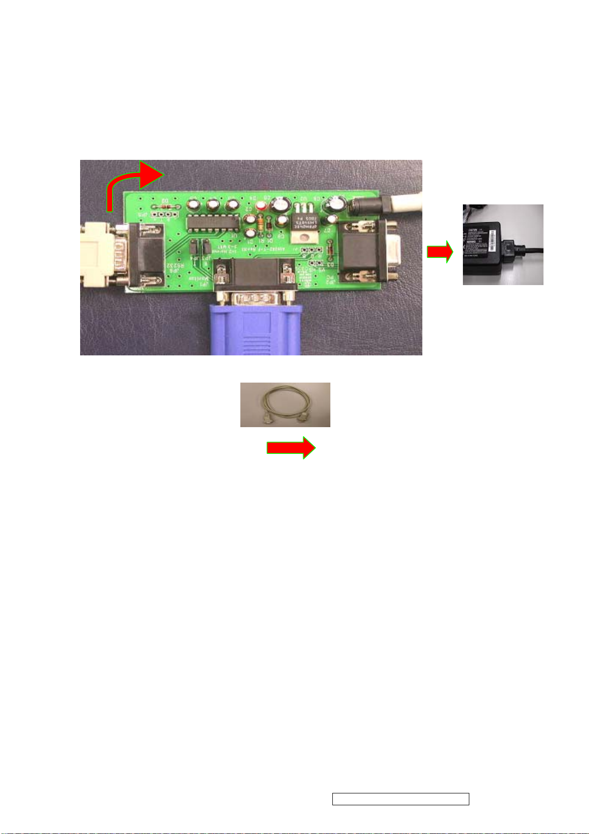
1.1.3 Join R232, monitor cable, and adapter. Detail, see the example picture as below.
Connect PC
Connect to adapter +12v
VGA
Cable
Connect monitor
ViewSonic Corporation Confidential - Do Not Copy VA912-2
26
Page 30
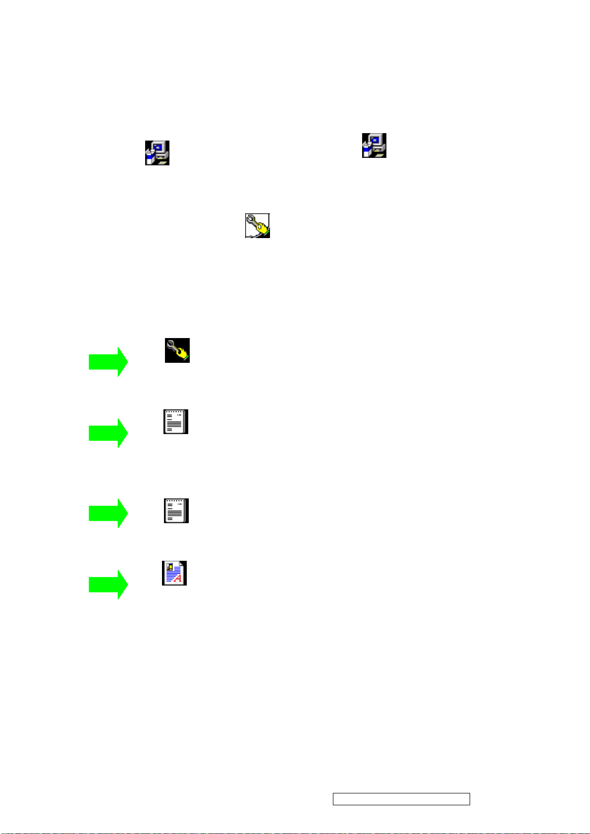
1.2 Installation:
A. Please install the programs respectively as below.
GProbe4.2.0.3.exe
Before Setup produce GProbe 4 file . Please set at ISP & BIOS software file.
B. I S & BIOS software file to be about to produce the next. (If the file existence already, needn’t to
ISP.GProbe
repeat.) This system is applied to Win 95/98/NT/2000.
1.3 ISP Executi on
Gprobe.exe
:ISP exe. Main program
GProbe4.2.0.3_gm5126.exe
: Drive write file.
Pre.txt
Readme.txt
5126bc14.dev
Please copy all the files above to the same directory
: Drive read file.
: Ancillary file.
ViewSonic Corporation Confidential - Do Not Copy VA912-2
27
Page 31
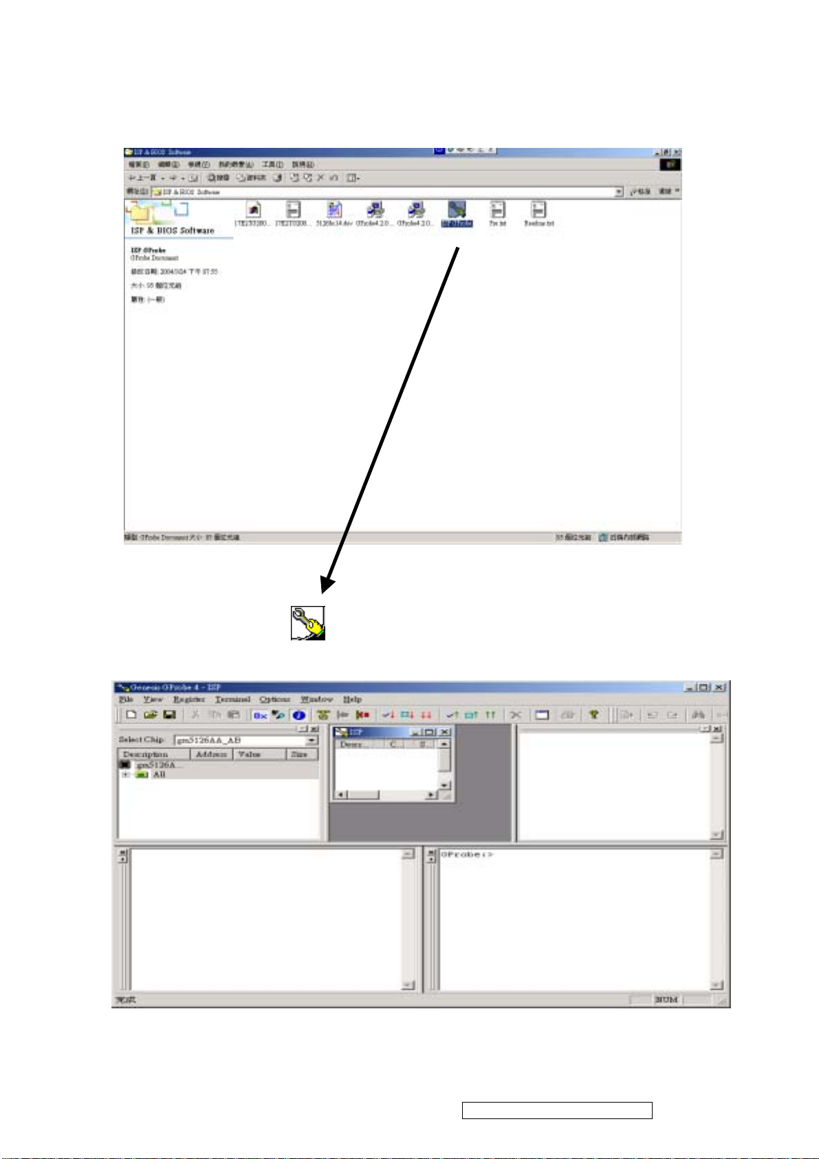
1. Open ISP.Gprobe while parameters set up have been completed.
ISP.GProbe
2. You will see the picture as below.
ViewSonic Corporation Confidential - Do Not Copy VA912-2
28
Page 32
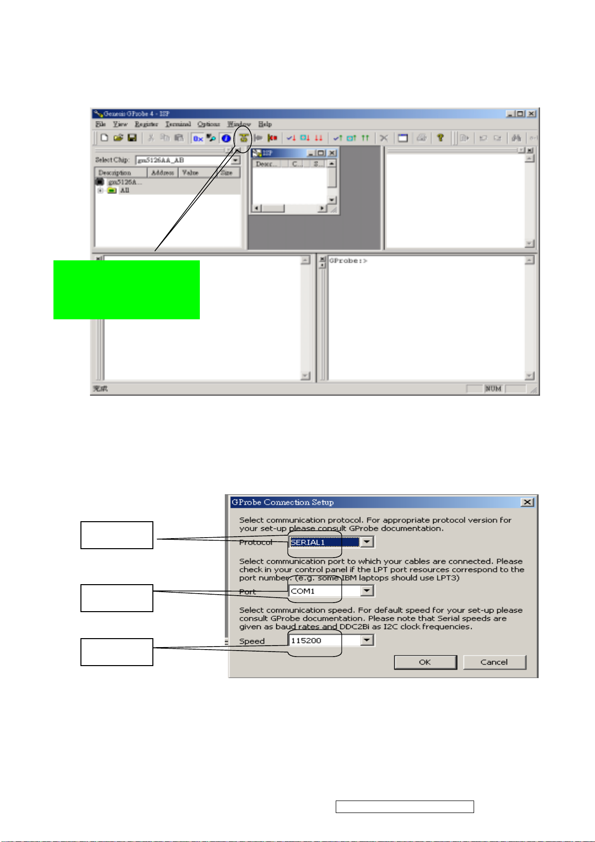
3. Execute the main program (Grope).
p
program executio
Choose the item for
arameter link while
n
4. Please follow up the parameter set up shown as below :
SERIAL1
COM1
115200
ViewSonic Corporation Confidential - Do Not Copy VA912-2
29
Page 33
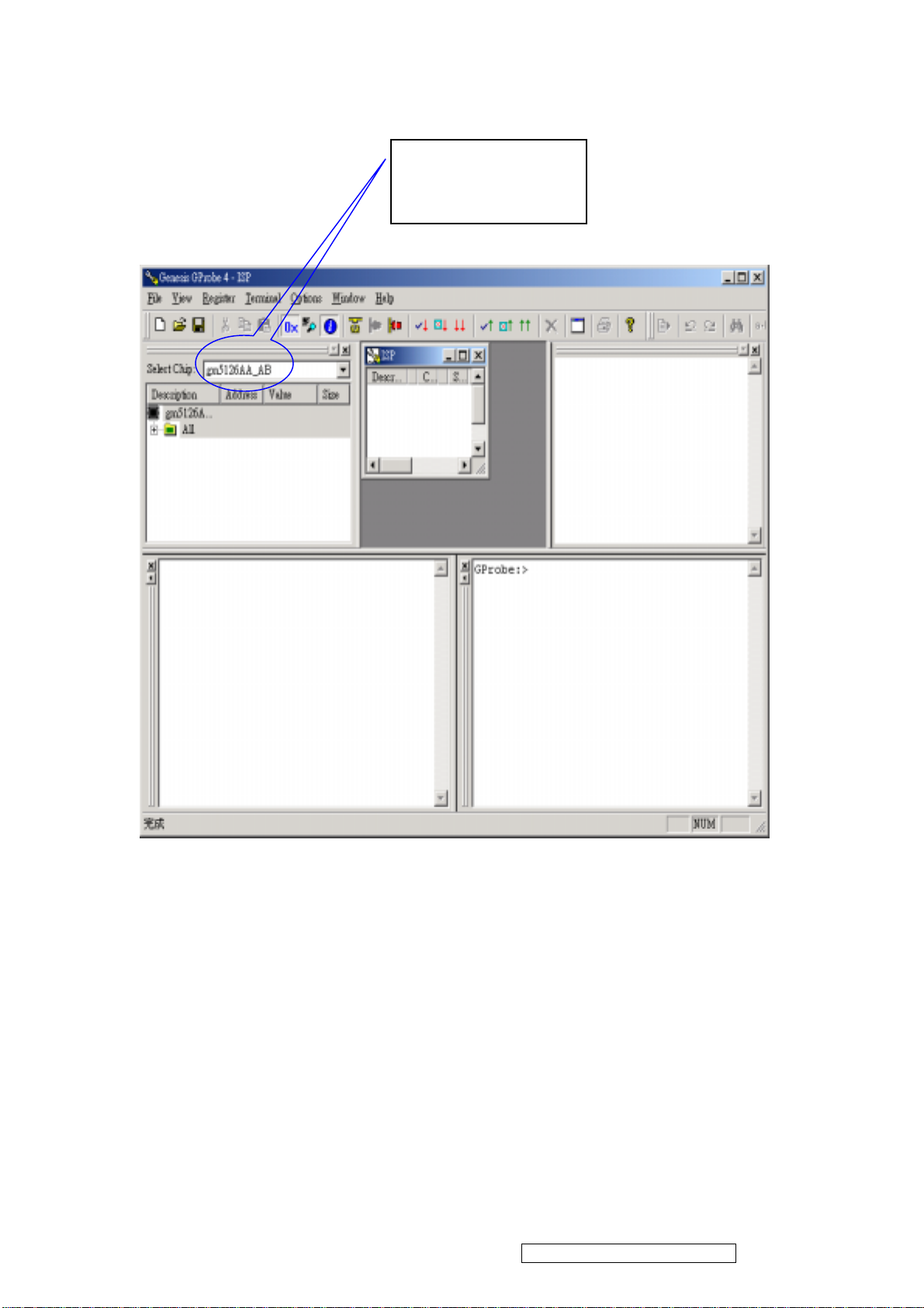
5. Select “gm5126AA_AB”
Select
“ gm5126AA_AB”
ViewSonic Corporation Confidential - Do Not Copy VA912-2
30
Page 34

6. Execute Pre.txt:Input BATCH PRE.TXT
The system can
execute ISP while the
words show up
Input “ BATCH
PRE.TXT”
If appear line 3 is OK,
Appear line 2 is Error.
Please check wiring.
ViewSonic Corporation Confidential - Do Not Copy VA912-2
31
Page 35
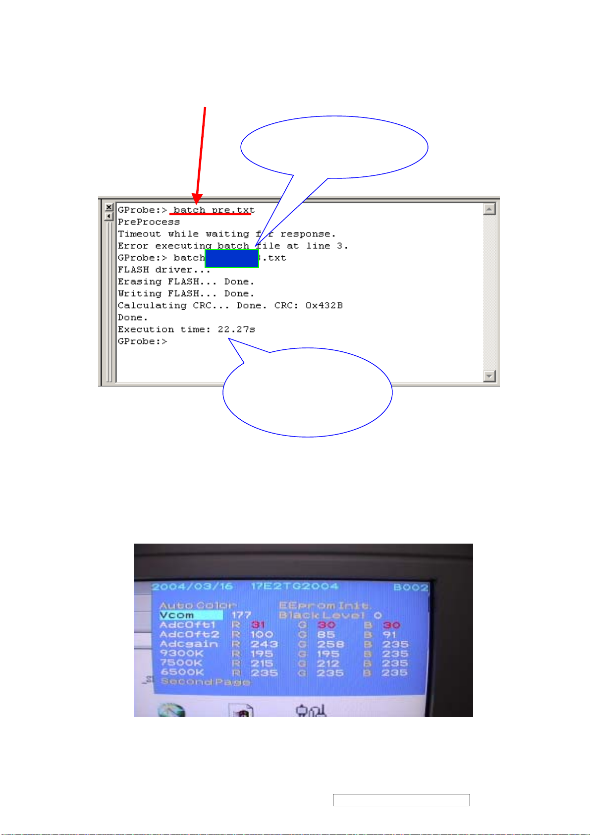
7. Please check the entity connection and execute Gprobe 4 again once Debug Mode did not show up
ISP Program execution:Input BATCH ( update of BIOS Rev) .TXT
Key “BIOS Rev.”
which you want here.
This is the “BIOS
update total
spending time”.
※ If failed, Please don’t turn off power. Repeat do it again, from step 6 to step 7.
8. When everything is done. Please turn off the power and restart it again.
Check Factory Mode and make sure it already be updated.
ViewSonic Corporation Confidential - Do Not Copy VA912-2
32
Page 36
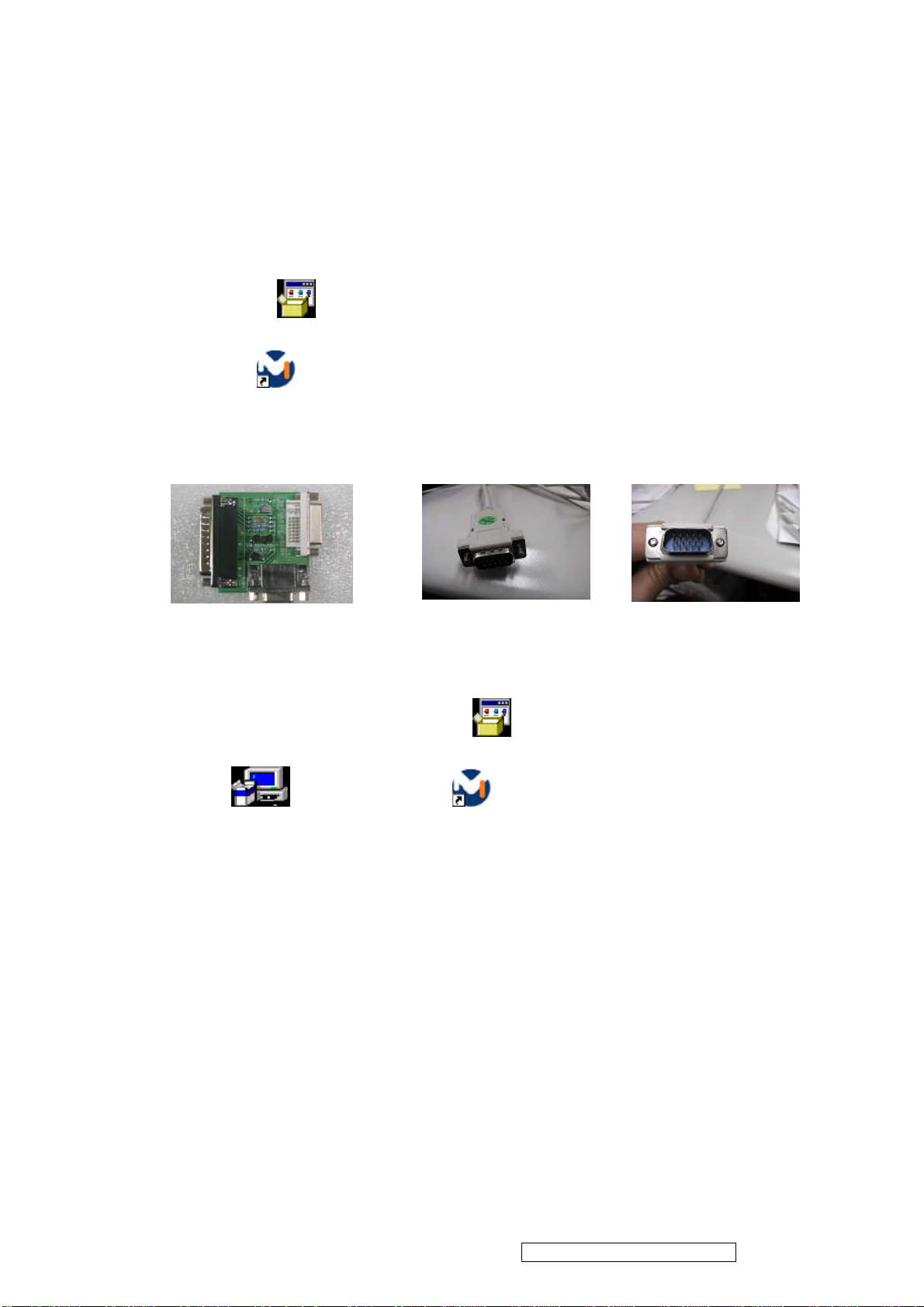
BIOS Update Flow for M-Star
1.1 Programs:
a.The file “Myson” from e-sir download for your needs. To discover ISP Software & BIOS two file.
b.Port95NT.exe: Print port IO tool.
C.M-Star ISP ISP main program (version might be different).
Port95nt.exe
Isp.lnk
1.2 Tools :
Interface Card Monitor (15 Pin VGA) Cable
1.3. Installation:
1-3-1 Software installation :
A. Please open ISP software file install Port95NT first then M -Star ISP.(Automatically
reboot PC) .
B. Setup the next, Produce the ,Please deposit to the “M-Star” ISP
software file from e-sir download.
The programs are compatible to Win 95/98/NT/2000.
Setup.exe
Port95nt.exe
Isp.lnk
ViewSonic Corporation Confidential - Do Not Copy VA912-2
33
Page 37

Kit equipped : PC & Notebook
Kit Insert PC Interface VGA Cable Insert KIT VGA Cable
Notebook Interface Kit Insert Notebook Interface VGA Cable Insert KIT
Double Click
1-3-2 Settings:
Isp.lnk
Fig.1: ISP Tool Main Menu
ViewSonic Corporation Confidential - Do Not Copy VA912-2
34
Page 38
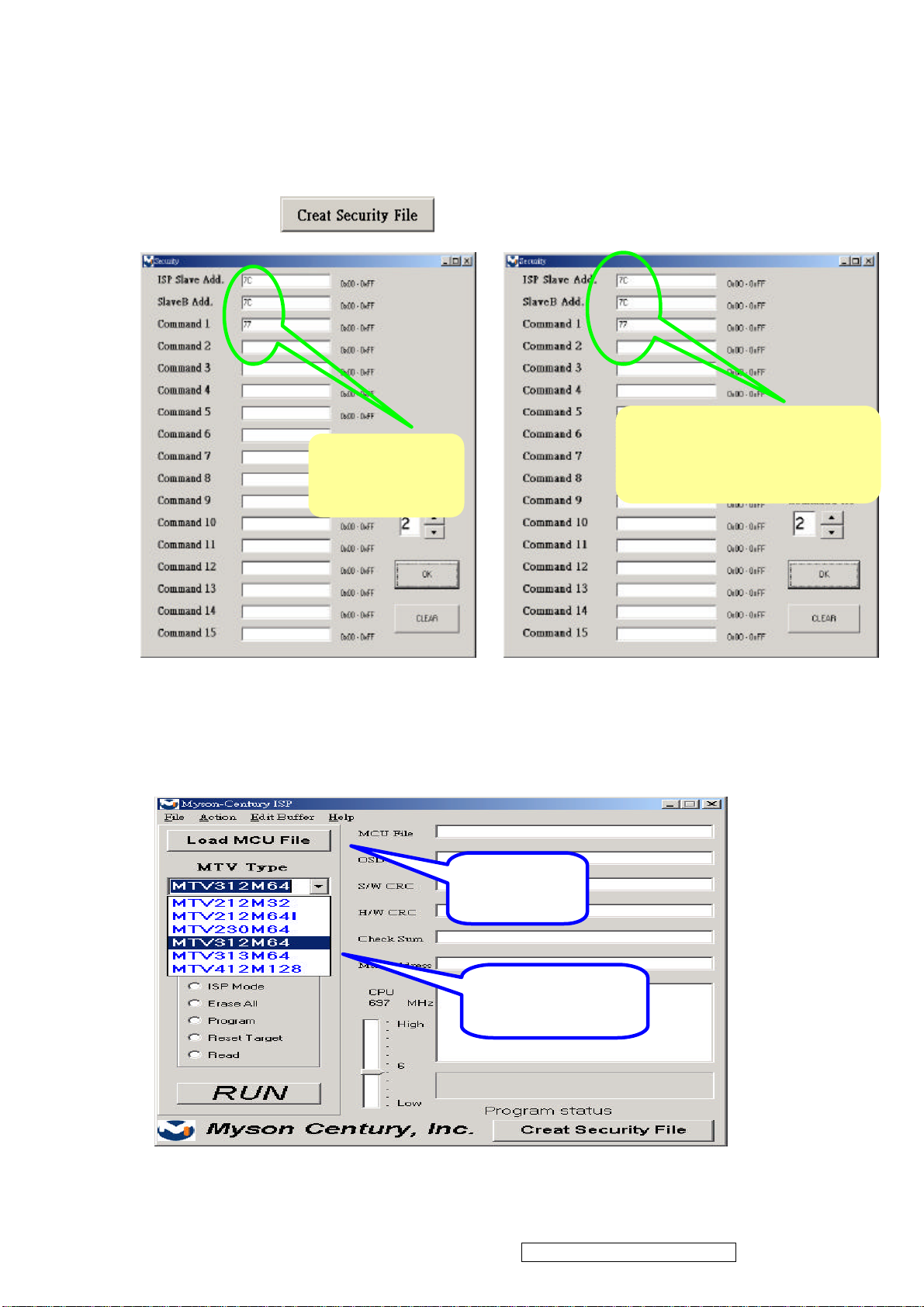
A190E1,E2,E3,A1
a. When ISP Tool executing at the first time, it is required to enter Security
Data Please press , then input related information as Fig.2.
7C 7C 77
For A150X2
7C 4C 77
For A170E1,E2
Fig.2: Security Data
b. Select correct Micro Controller as Fig.3.
Step 2
Load MCU File
Step 1
Select MTV312M64
ViewSonic Corporation Confidential - Do Not Copy VA912-2
35
Page 39
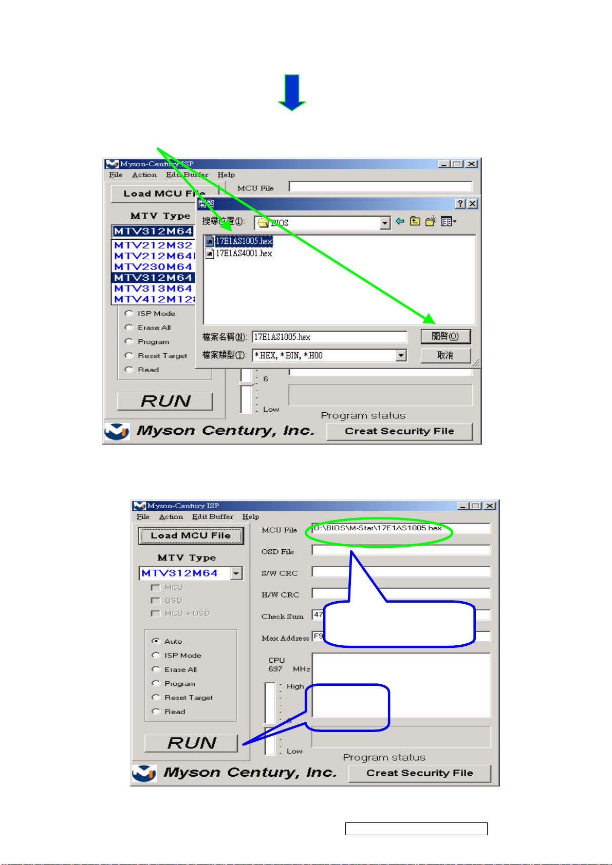
C. Installation software , Select want download
The path of software location
correct file.
Fig.3: Select Micro Controller
Step 3 Example :
Step 4
Press RUN
ViewSonic Corporation Confidential - Do Not Copy VA912-2
36
Page 40
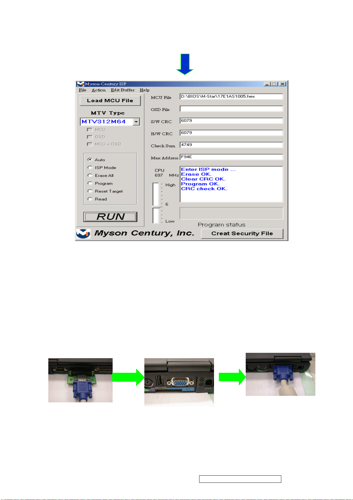
1.4. Verification BIOS Update whether success
To open factory mode window & Check BIOS Version whether change .
1. 5. Verification
Change VGA cable to normal display Mode
Kit & VGA Cable separate from
Notebook or PC Interface
VGA Cable Insert
Notebook or PC Interface
ViewSonic Corporation Confidential - Do Not Copy VA912-2
37
Page 41
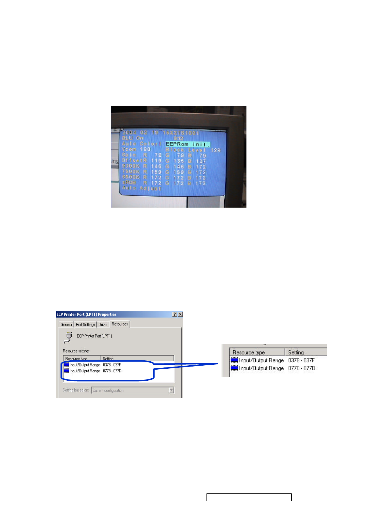
1.6. Check Factory Mode whether change.
The mode of operations, Please to refer to e-SIR “BIOS Judgement Type”.
Pattern display as below:
※ If there is any concern to take place,Please check following action.
Setting printer port “0378-037F”
ViewSonic Corporation Confidential - Do Not Copy VA912-2
38
Page 42
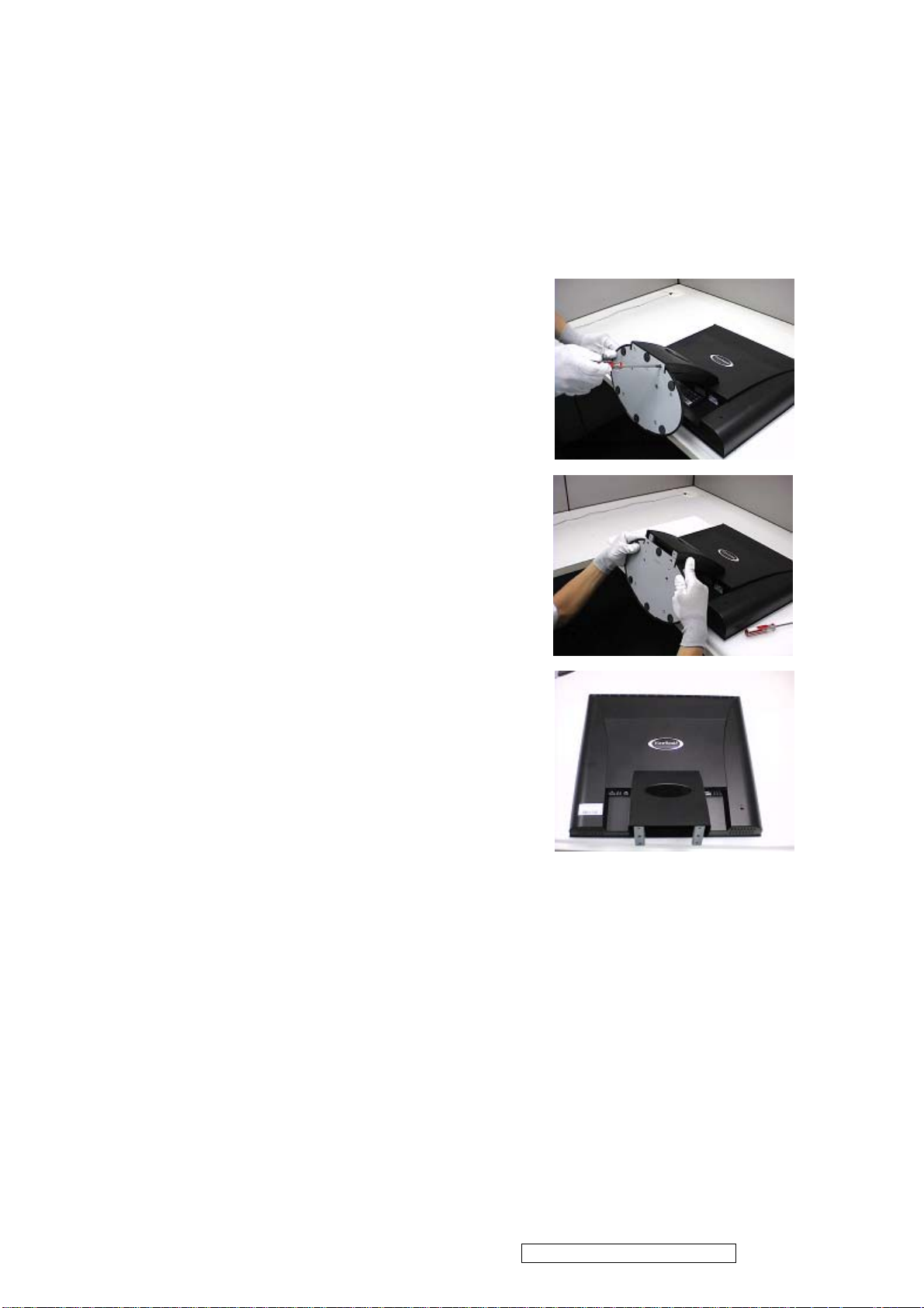
Monitor Assembly and Disassembly
1 Separate Stand Assy
1.1 Remove Stand Cover
Step 1 :
Loose and remove 4 screws.
Step 2 :
Remove the Stand Cover.
Step 3 :
Completed.
ViewSonic Corporation Confidential - Do Not Copy VA912-2
39
Page 43
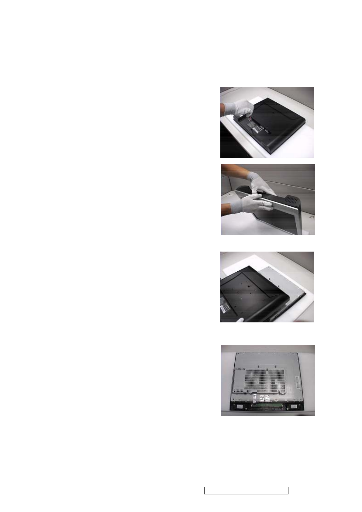
2 Separate Rear Cover (Rear Case Assy)
Separate Bezel hooks to take Bezel and Rear Cover apart.
Step 1 :
Loose and remove 5 screws.
Step 2 :
Separate Bezel hooks to take
Bezel and Rear Cover apart.
Step 3 :
Remove Rear Cover.
Step 4 :
Completed.
ViewSonic Corporation Confidential - Do Not Copy VA912-2
40
Page 44

3 Remove Power Board
3.1 Remove Metal Cover
Step 1 :
Loose and remove 3 screws.
Step 2 :
Loose and remove 2 screws of Analog Socket.
Step 3 :
Remove FFC from OSD Board.
Step 4 :
Remove the Metal Cover.
ViewSonic Corporation Confidential - Do Not Copy VA912-2
41
Page 45
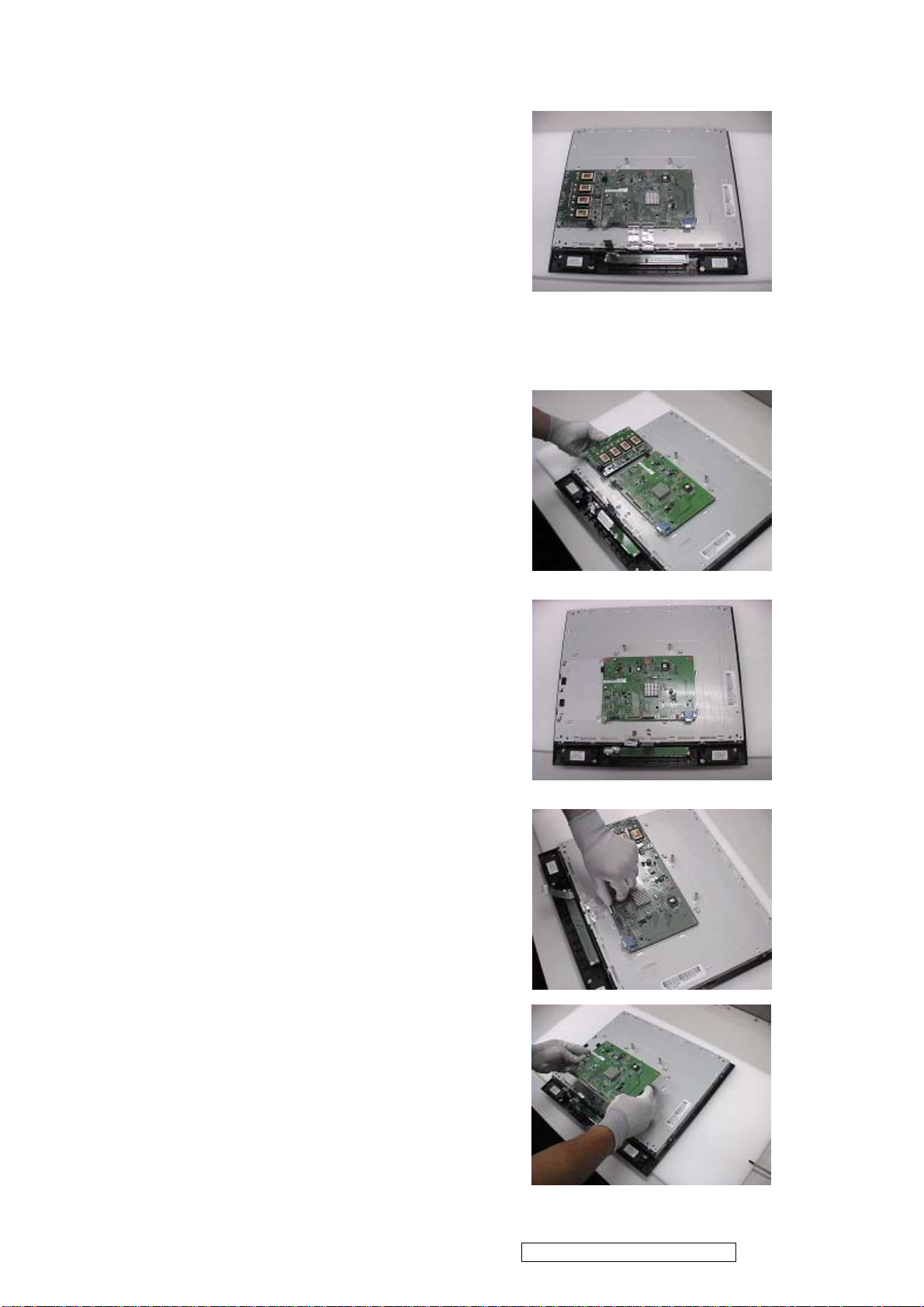
Step 5 :
Completed.
3.2 Remove Power Board and AD Board
Step 1 :
Loose and remove 3 screws.
Then remove Power Board.
Step 2 :
Completed.
Step 3 :
Remove FFC from X Board.
Step 4 :
Loose and remove 4 screws.
Then remove AD/B.
ViewSonic Corporation Confidential - Do Not Copy VA912-2
42
Page 46
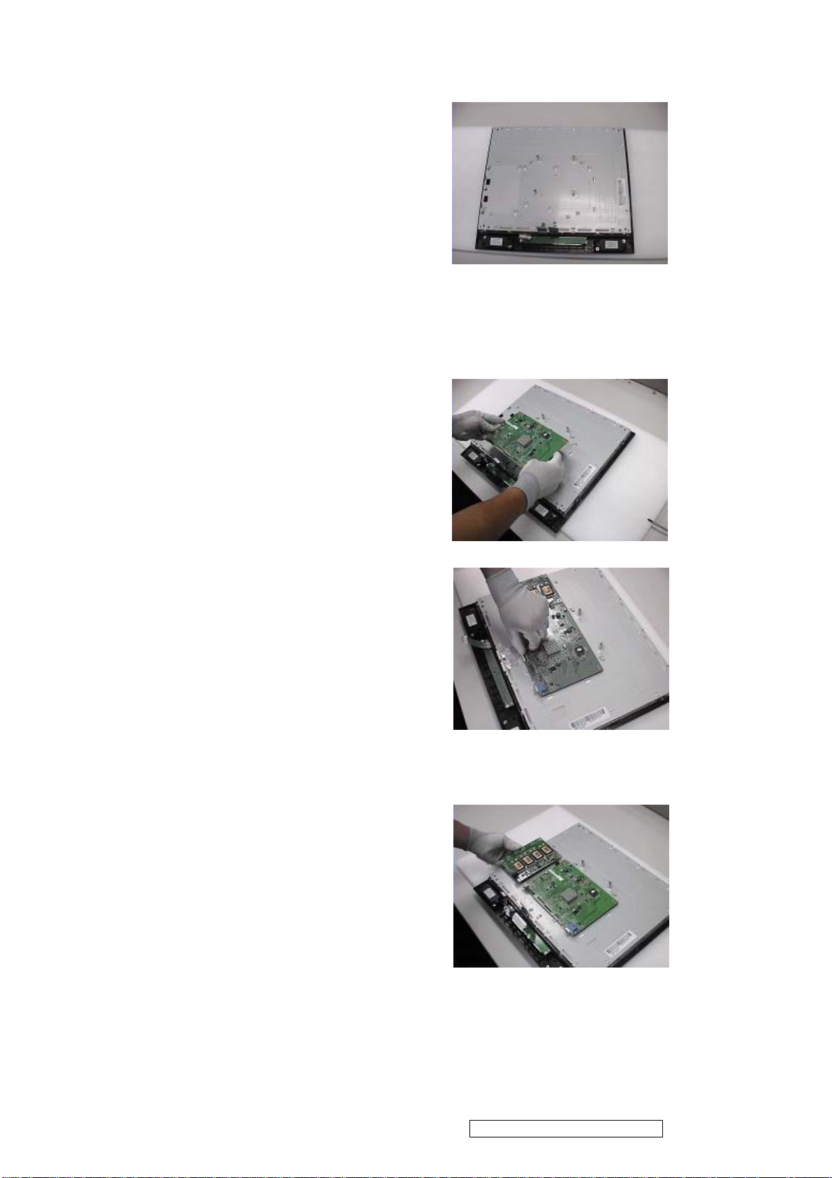
Step 5 :
Completed.
4 Change New Power Board and AD Board
Step 1 :
Insert New AD Board.
And fasten 4 fixed screws.
Step 2 :
Insert FFC.
Step 3 :
Insert New Power Board.
And fasten 3 fixed screws.
ViewSonic Corporation Confidential - Do Not Copy VA912-2
43
Page 47
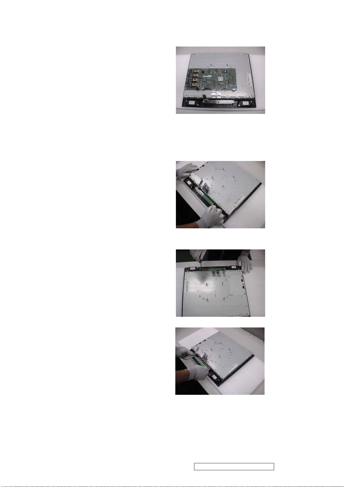
Step 4 :
Completed
5. Remove OSD Board
Step 1 :
Separate both Audio Cable.
Step 2 :
Loose and remove 2 screws.
Step 3 :
Take OSD Board apart.
ViewSonic Corporation Confidential - Do Not Copy VA912-2
44
Page 48
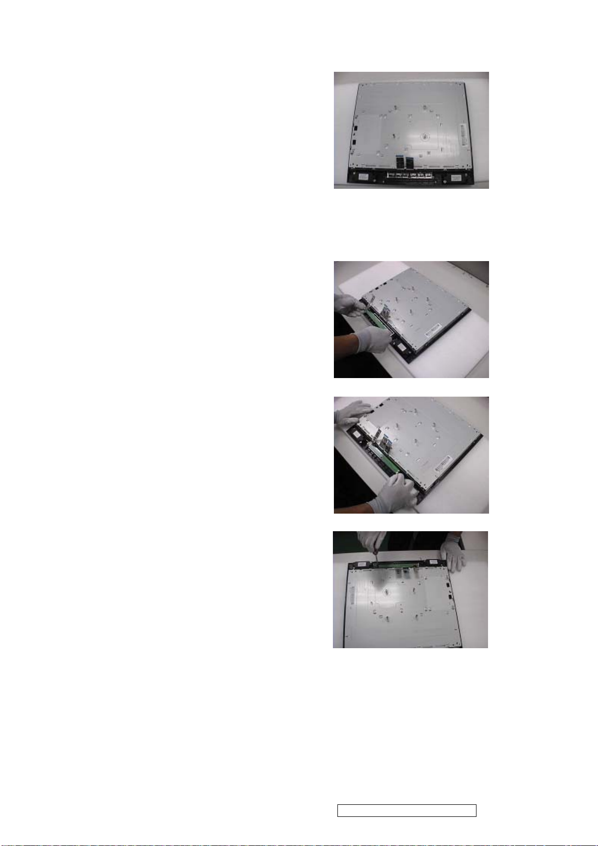
Step 4 :
Completed.
6.Change New OSD Board
Step 1 :
Place New OSD Board.
Step 2 :
Insert Audio cable to connectors of
New OSD Board.
Step 3:
Fasten 2 fixed screws
ViewSonic Corporation Confidential - Do Not Copy VA912-2
45
Page 49
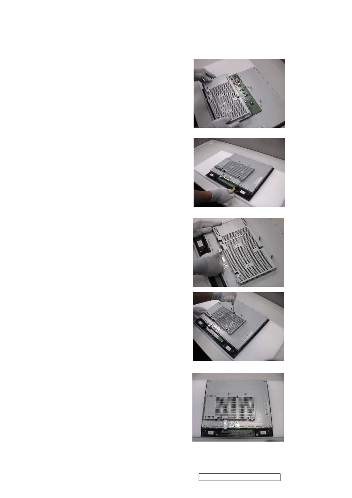
7. Add Cover to AD PCB Heatsink
Step 1 :
Join the cover hooks of X-PCB.
Step 2 :
Fasten 2 fixed screws of Analog
Socket.
Step 3 :
Insert FFC.
Step 4 :
Fasten 3 fixed screws
Step 5 :
Completed.
ViewSonic Corporation Confidential - Do Not Copy VA912-2
46
Page 50
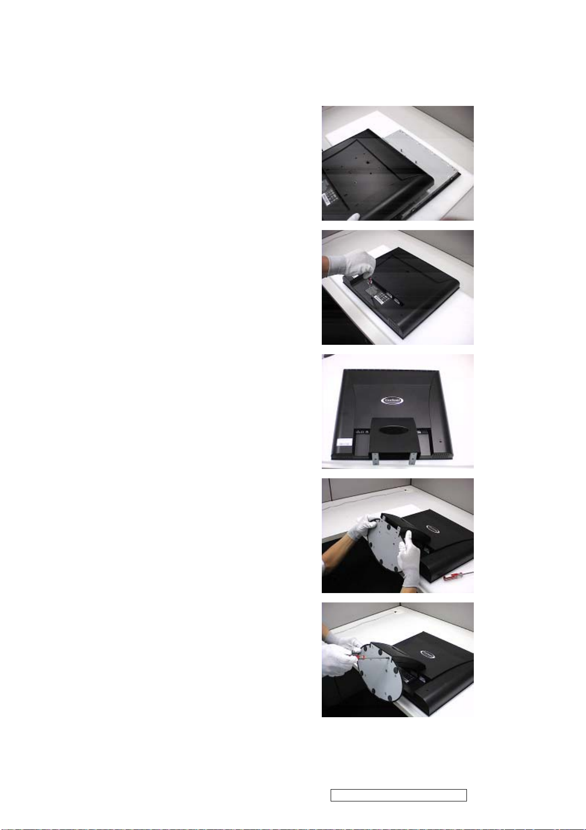
8. Rear Assy & Stand Assembly
Step 1 :
Place Rear Cover.
Step 2 :
Fasten 5 fixed screws.
Step 3 :
Completed.
Step 4 :
Place Stand Assy.
Step 5 :
Fasten 4 screws to fixed Stand Assy.
ViewSonic Corporation Confidential - Do Not Copy VA912-2
47
Page 51
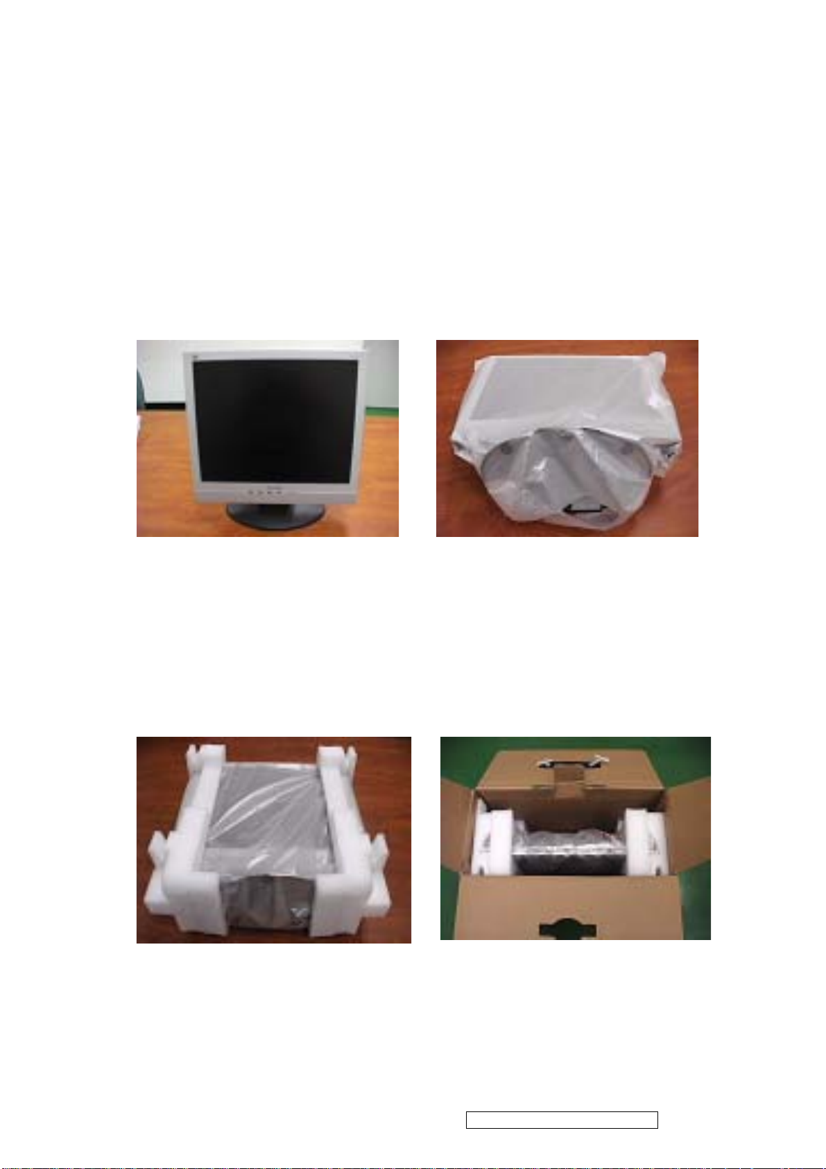
Packing Procedure
1.1 Paste protection film to protect the monitor. (Figure 1)
1.2 Put the monitor in the PE bag and seal the bag with tape. (Figure 2)
Figure 1 Figure 2
1.3 Put the cushions on the monitor. (Figure 3)
1.4 Place the monitor into the carton and then put all the accessories into the
carton. As last, close the carton and seal it with tape. (Figure 4)
Figure 3
Figure 4
ViewSonic Corporation Confidential - Do Not Copy VA912-2
48
Page 52
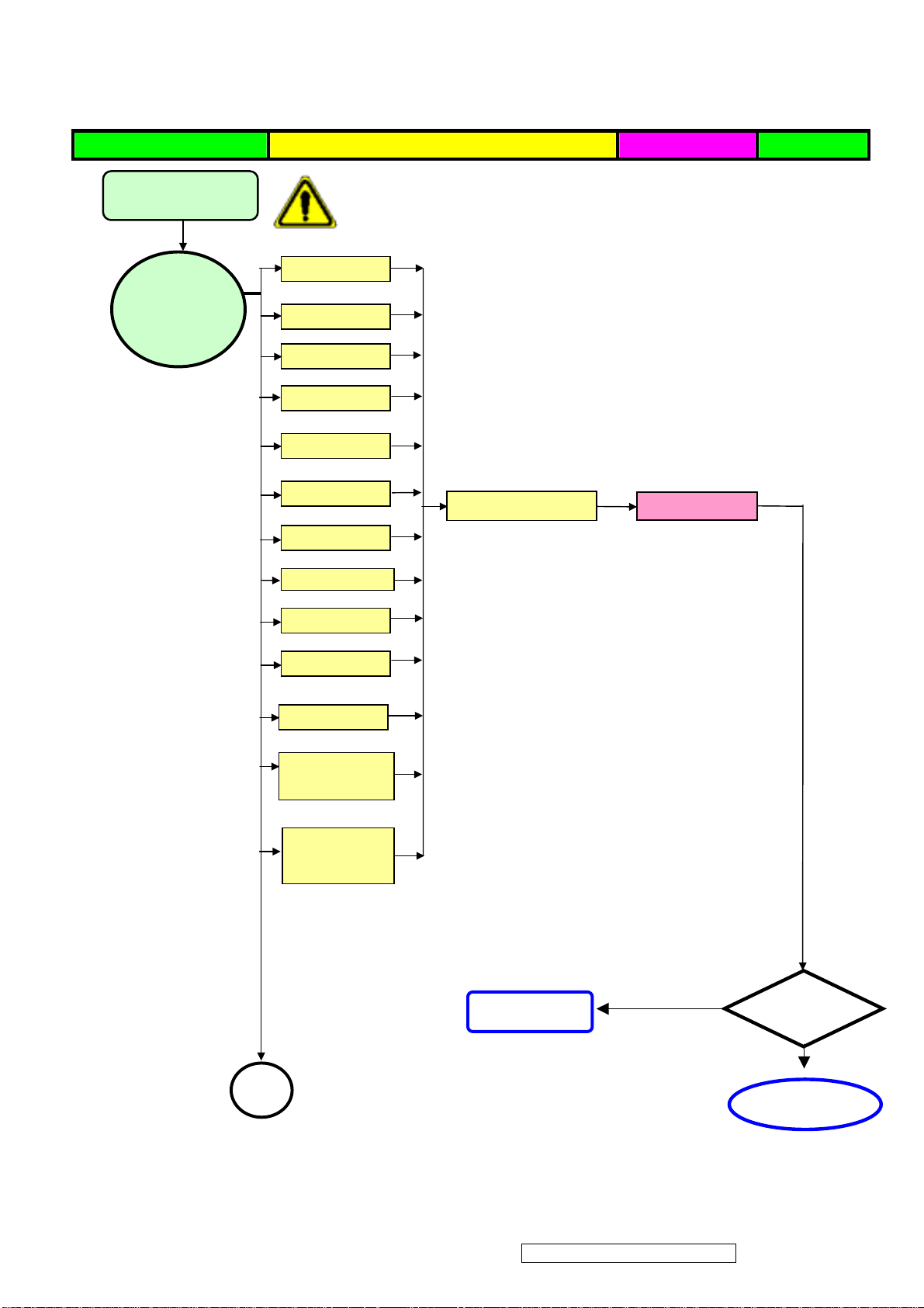
Defect Mode Failure Analysis Repair Testing
p
Light On Test
※ “ Panel Change” Should be Performed to Level 3 Repair
Abnormal
Display
Flash Dots
Bright Dot
Dark Dot
Backlight
Light Leakage
Mura
Image Sticking
Brightness spot
Check Panel
Panel Change
Particle
Dot Defect
Image Remain
Group Bright
Dots
Others Cosmetics
Defect
Next Ste
NG
TEST
A
Completed
ViewSonic Corporation Confidential - Do Not Copy VA912-2
43
Page 53

Defect Mode Failure Analysis Repair Testing
A
A
p
A
※ “ Panel Change” Should be Performed to Level 3 Repair
A
Display Noise
Power on
Check PCB
AD/B Change
Display
bnormal
Power/B Change
Inverter/B Change
Flicker
CNT/B Change
Beat Display
Flicker
Beat Display
Shut Down
Check Panel
Panel Change
Display Wave
Check PCB
AD/B Change
Power/B Change
CNT/B Change
Check Panel
Panel Change
No Backlight
Check Adapter
Adapter Change
Next Ste
NG
TEST
B
Completed
ViewSonic Corporation Confidential - Do Not Copy VA912-2
50
Page 54
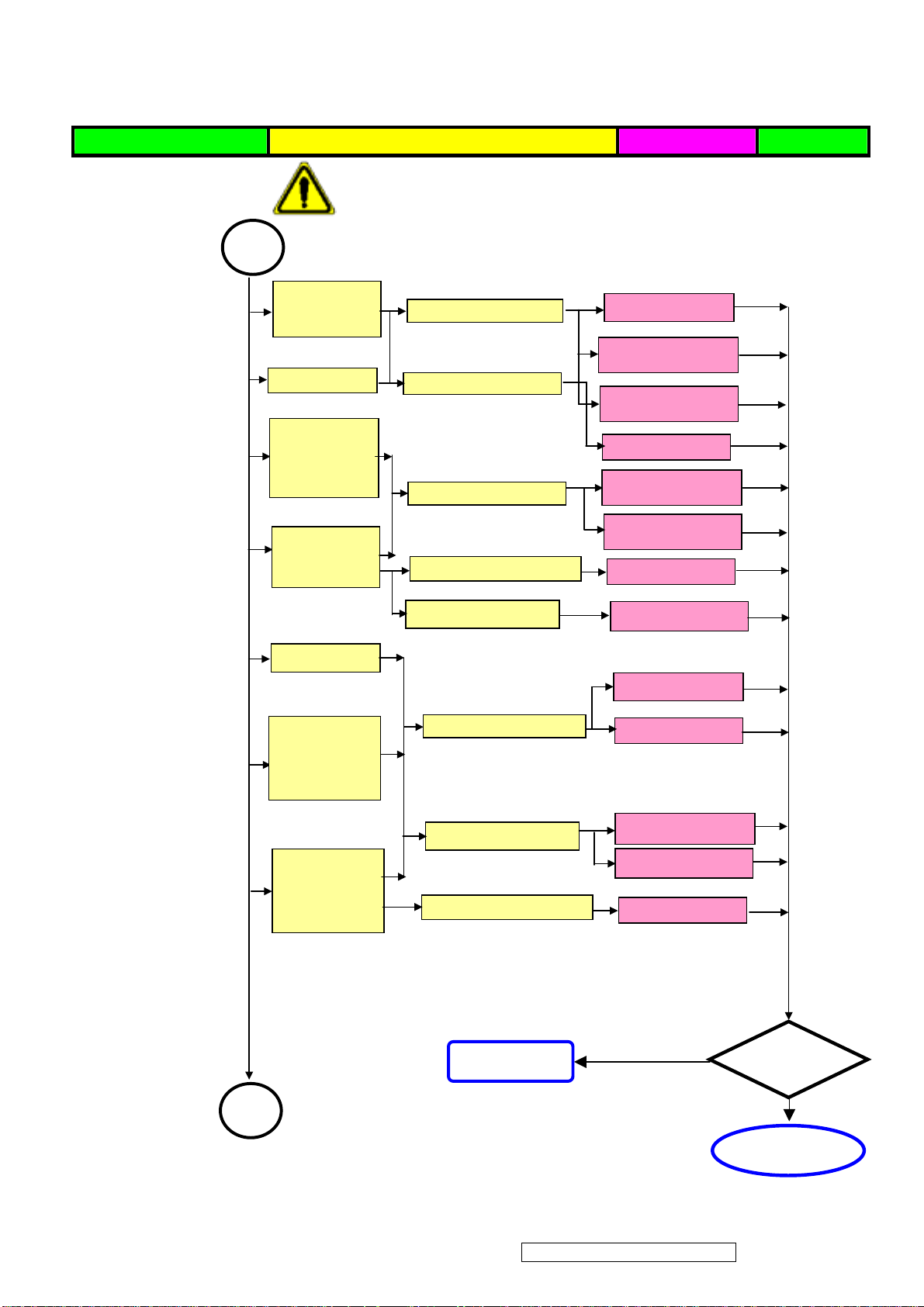
A
A
p
A
A
A
A
Failure Analysis Repair Testing
※ “ Panel Change” Should be Performed to Level 3 Repair
B
Display White
Out
Check PCB
AD/B Change
Power/B Change
Booting Delay
Brightness
Even
Abnormal
Check PCB
Check PCB
Inverter/B Change
OSD/B Change
Power/B Change
Beat Display
No Backlight
Check Panel
Inverter/B Change
Panel Change
Check Adapter
Adapter Change
No signal
AD/B Change
R.G.B
Display
bnormal
Check PCB
CNT/B Change
Gray Scale
Display
bnormal
Check Wire
Check Panel
VGA cable
DVI cable
Panel Change
Next Ste
NG
TEST
C
Completed
ViewSonic Corporation Confidential - Do Not Copy VA912-2
51
Page 55
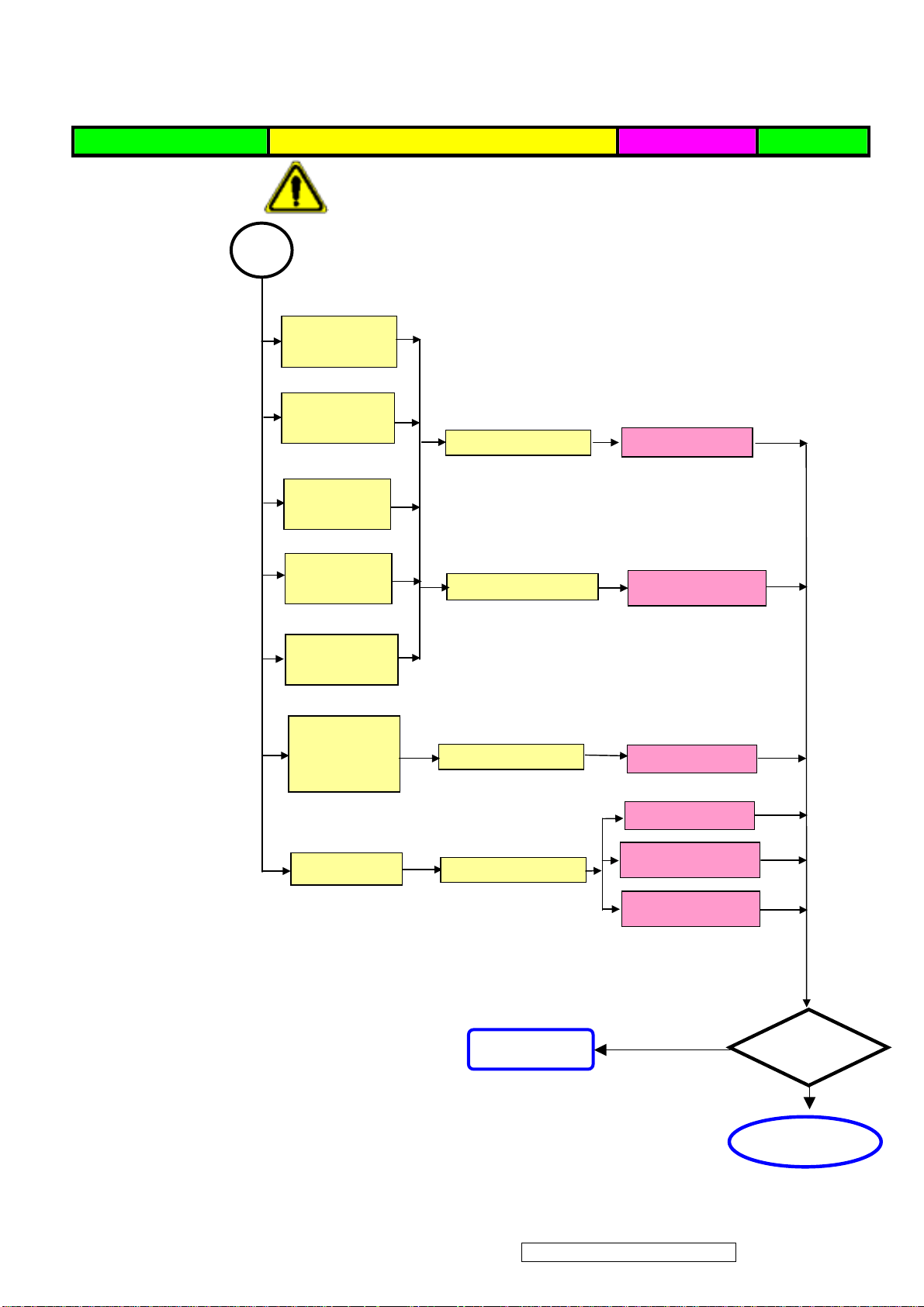
Defect Mode Failure Analysis Repair Testing
A
p
A
A
C
※ “ Panel Change” Should be Performed to Level 3 Repair
Horizontal
Line Defect
Vertical
Weak Line
Horizontal
Weak Line
Check PCB
AD/B Change
Vertical
Band Defect
Check Panel
Panel Change
Horizontal
Band Defect
Power Saving
Display
Abnormal
Check PCB
AD/B Change
AD/B Change
Peculiar Smell
Check PCB
Power/B Change
Inverter/B Change
Next Ste
NG
TEST
Complete
ViewSonic Corporation Confidential - Do Not Copy VA912-2
52
Page 56
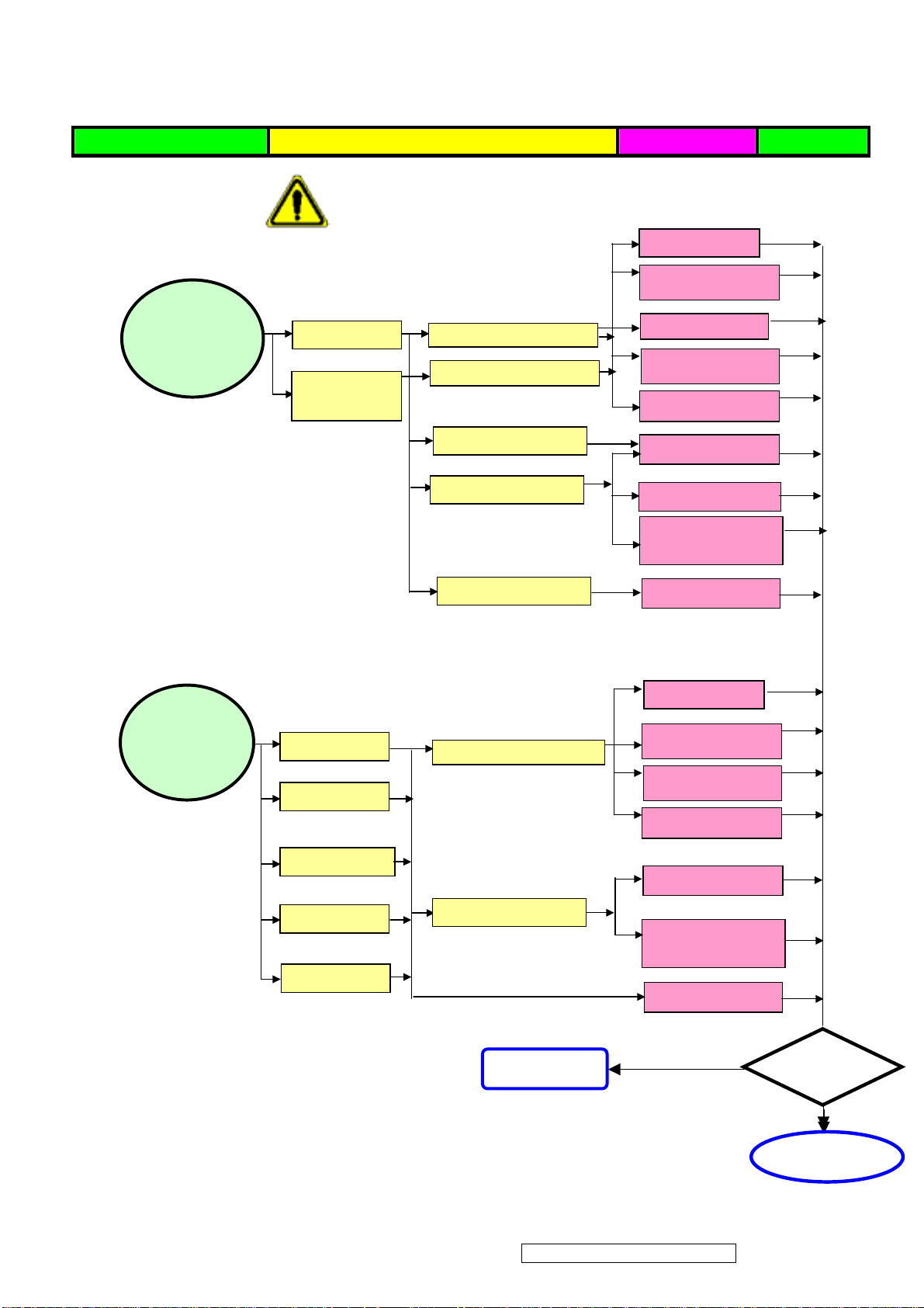
Defect Mode Failure Analysis Repair Testing
r
r
g
g
p
※ “ Panel Change” Should be Performed to Level 3 Repair
AD/B Change
Power/B Change
Power ON/OFF
Abnormal
No Powe
Turn Off
Check PCBA
Check PCBA
Abnormal
CNT/B Change
Inverter/B
OSD/B Change
Check Wire
Check Wire
Check Adapter
OSD Cable
AC Power Change
DC Power CNT
Cable Chan
Adapter Change
e
LED Display
Abnormal
LED Off
LED Dark
Check PCBA
AD/B Change
Power/B Change
Inverter/B
OSD/B Change
LED Abnormal
LED Loss
LED Flicke
Check Wire
OSD Cable
DC Power CNT
Cable Chan
Adapter Change
e
NG
Next Ste
ViewSonic Corporation Confidential - Do Not Copy VA912-2
53
TEST
Completed
Page 57
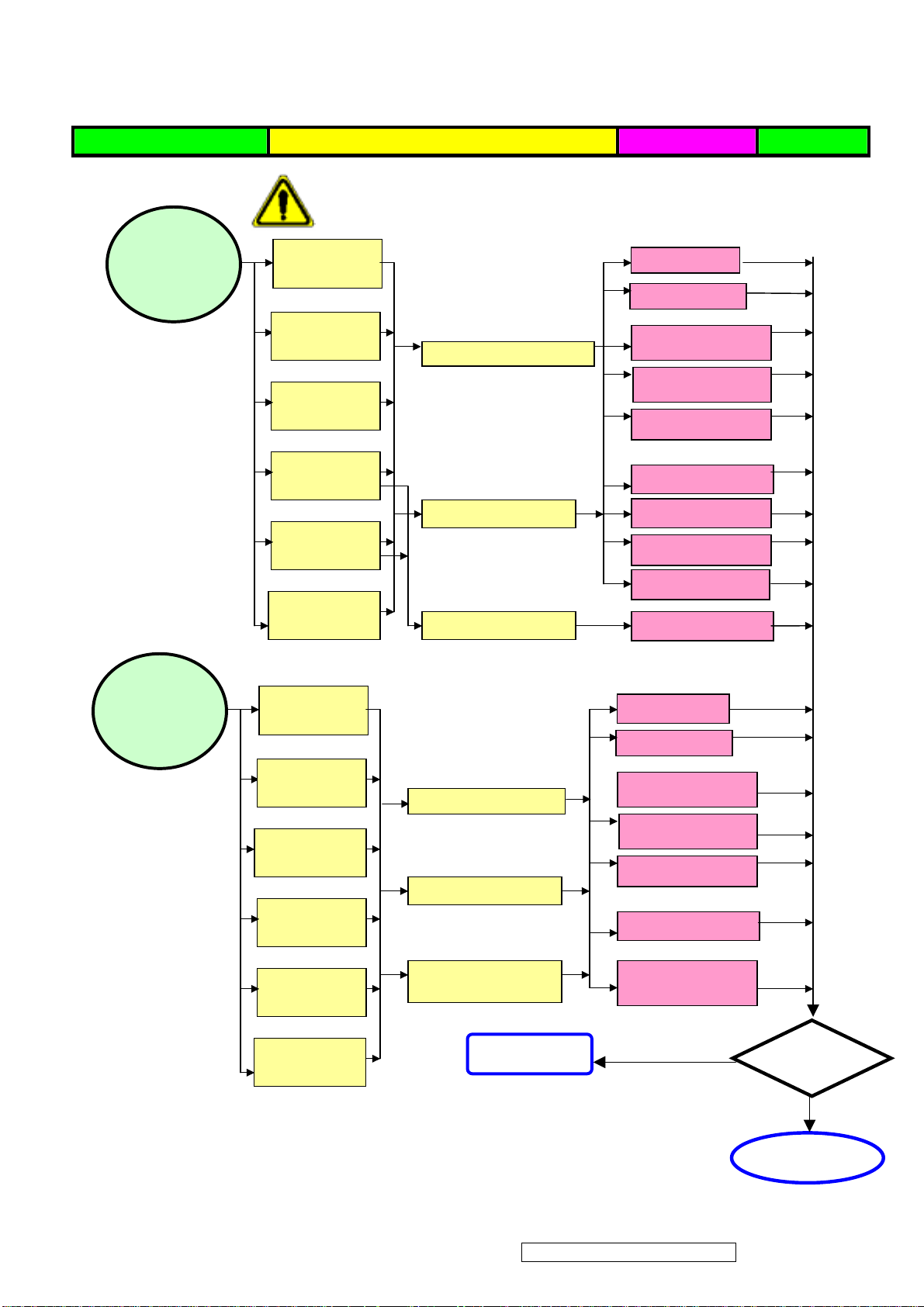
Defect Mode Failure Analysis Repair Testing
p
p
Abnormal BIOS
&OSD
※ “ Panel Change” Should be Performed to Level 3 Repair
OSD Key
Unavailable
OSD Can’t
Input
OSD Can’t
Check PCB
AD/B Change
CNT/B Change
Power/B Change
Inverter/B
Abnormal
Louds
eaker
Read
OSD No
Display
OSD Jiggle
OSD Display
Abnormal
Voice Loss
Check Wire
Check BIOS
Abnormal
Loud
L/R
Abnormal
Check PCBA
Check Wire
OSD/B Change
D-sub cable
OSD cable
VGA cable
DVI cable
BIOS Update
AD/B Change
CNT/B Change
Power/B Change
Inverter/B Change
OSD/B Change
No Voice
L/R Same
Volume
Check Loudspeaker
OSD Cable Change
Loudspeaker
Change
ViewSonic Corporation Confidential - Do Not Copy VA912-2
Loudspeaker
Noise
Next Ste
54
NG
TEST
Completed
Page 58
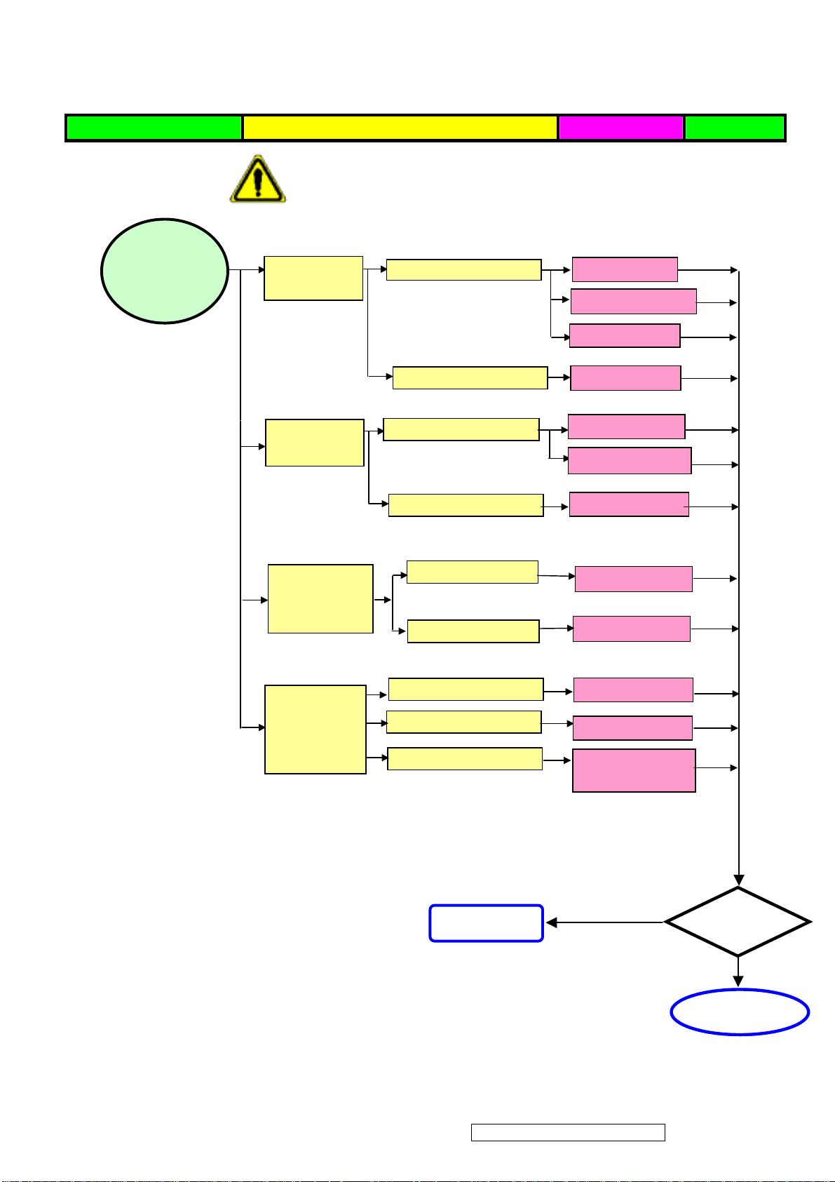
Defect Mode Failure Analysis Repair Testing
A
p
Other Abnormal
Display
※ “ Panel Change” Should be Performed to Level 3 Repair
Display Shut
Down
Check PCB
AD/B Change
Power/B Change
CNT/B Change
Check Panel
Panel Change
Display Flicker
((tapping )
Check PCBA
AD/B Change
CNT/B Change
Check Panel
Panel Change
DVI Signal
Display
Check PCB
AD/B Change
Abnormal
EDID Update
TV Function
Display
Abnormal
Check PCBA
Check Wire
Check Controller
TV /B Change
AV Cable Change
Remote controller
Change
Next Ste
NG
TEST
Complete
ViewSonic Corporation Confidential - Do Not Copy VA912-2
55
Page 59

6. Troubleshooting Flow Chart
Check the information in this section to see if the problems can be solved before requesting repair.
Note:The consumers are only allowed to solve the problems described as below. Any
unauthorized product modification, or failure to follow instructions supplied with the product
will end the warranty immediately.
No image
Make sure power button is ON.
Check whether the LCD monitor and computer power cords are plugged and whether there is a
supply of power.
No Signal Input
Check the signal connection between the computer and LCD monitor.
“Out of Range”
Check the computer image output resolution and frequency and compare the value with the
preset values (Please refer to [Appendix-Display Mode]).
Fuzzy Image
Adjust Phase.
Image too bright
Adjust brightness and contrast by OSD.
Image too dark
Adjust brightness and contrast by OSD.
Irregular image
Check the signal connection between the computer and LCD monitor.
Perform Auto Adjust.
Distorted image
Reset the LCD monitor
Take off extra accessories (such as signal extension cord).
Image is not centered
Use OSD Image Menu to adjust H_Position and V_Position.
Check image size setting.
Perform Auto Adjust.
ViewSonic Corporation Confidential - Do Not Copy VA912-2
56
Page 60

Size is not appropriate
Use OSD Image Menu to adjust H_Position and V_Position.
Check image size setting.
Perform Auto Adjust.
Uneven color
Use OSD Color Menu to adjust color setting.
Color too dark
Use OSD Color Menu to adjust color setting.
Dark area distorted
Use OSD Color Menu to adjust color setting.
White color is not white
Use OSD Color Menu to adjust color setting.
ViewSonic Corporation Confidential - Do Not Copy VA912-2
57
Page 61
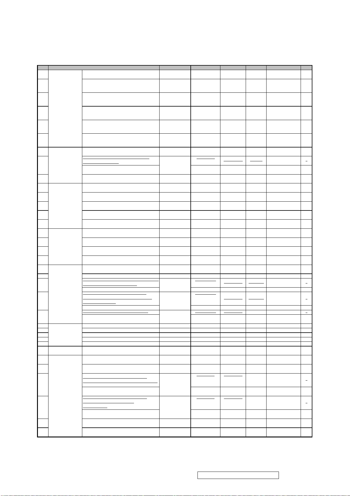
Serial No. Prefix: PQU
MENU for VSC_VA912+Caution Card_for USA,Complex,4C,A190E2-H06
Above listed items are examples, supplier can
All revised RSPLs with newly added items or any change made should be highlighted and correlated with the ECN/ECR approved by
7. Recommended Spare Parts List
ViewSonic Model Number: VS10696-2E
RECOMMENDED SPARE PARTS LIST (VA912-2)
Rev: 1b
Item ECR/ECN ViewSonic P/N Ref. P/N Location Universal number# Q'ty
Accessories:
1
2
3
4
5
6
Board Assembly:
7
8
9
Cabinets:
10
11
12
13
14
Cables:
15
16
17
18
Documentation:
19
20 Label, Bar-Code Labe, 55*13mm DC-00002073 7741519181 1
21 01/16/06: Removed
22
23
24 Screw,M3*P0.5*4,f5.5*2,Steel 01/16/06: Added HW-00000553 42A9930008 2000
Hardware:
25 Stand-Off 4 #-40*11.8 01/16/06: Added M-00000559 42A9940007 2000
26 Screw,f3*P1.27*8,f5.5*2,Steel 01/16/06: Added HW-00000557 42A9930017 2000
27 Screw,M3*P0.5*6,Steel 01/16/06: Added HW-00000555 42A9930014 2000
28 Screw,f3*P1.27*12,f5.5*2,Steel 01/16/06: Added HW-00000556 42A9990005 2000
29
Miscellaneous:
Packing Material:
30
31
32
33
34
35
Description
Adapter, UP06511190-08B, 19 V, 3.42 A, 65 W,
Black, Potrans, Two BC
Power Cord, BSI, H05VV-F, 0.75mm2, 3C, LP60L+LS-60, L=1830+/-50mm, Black, 18AWG,
PSB Mark, Linetek, No Bag
Power Cord, CCC, 300/500V, 0.75mm2, 3C, PC323+COC-01, L=1830+/-50mm, Black, Linetek,
18AWG, No Bag
Power Cord, CEE, SP-023+IS-14, H05VV-F, 3G,
0.75mm2, CT-12, L=1800+/-50mm, I-SHENG,
18AWG, Black, No Bag
Power Cord, JIS, VCTF, 0.75mm2, 3C, LP54+LS13J, L=1830+/-50mm, Black, Linetek, 18AWG, No
Bag
Power Cord, UL, SVT#18/3C, 75 degree Celcuis,
LP-30B+LS-13, L=1830+/-50mm, Black, Linetek,
18AWG, No Bag
DC/AC Inverter, TWS-444-983, 4.8, mA, 2900 V,
Sumida
PCBA for , A190E2-T, A190E2-H-S, 203-04,
Rev.02, OSE/USI, ODM
PCBA for ,A190E2-H,A190E2-H-S1,201-05,Rev.
04,ODM
PCBA For A190E2-T, A190E2-H-K, Rev.02, Rigid,
203-01(ODM)
Bezel Assy, A190E2-H06, ASSY, Pantone 877C
silver, Fuking
Cover AD(W/O DVI-D Hole), A190E2, SECC,
t=0.6mm
Cover Hinge Assy, A190E2-H06, ASSY, J91A11B5
Black, Fuking
Rear Assy, A190E2-H06, ASSY, J91A11B5 Black,
Fuking
Stand Seat Assy, A190E2-H06, ASSY, J91A11H8
Black, Fuking
Audio Cable, A150X2, 18AWG, 180cm, Black,
JCE
FFC_X, A190E2, 45PIN, 60x23mm,
PITCH=0.5mm
FFC-OSD, A190E2-H01, 15Pin, 90mm*14mm,
Pitch=1.0mm
Monitor Cable, A150X2, 30AWG, 180cm, Black,
JCE
Carton Label Label, A190E2-H06, 76.2 mm, 76.2
mm
MENU for VSC_VA912_Analog, Complex, 4C, YiChing Special Printing, A190E2-H06
MENU for VSC_VA912,Complex,4C,A190E2-H06 DC-00002372 76-D001512 1
MENU for VSC_VA912b_Analog+Caution
Card_for USA, Complex, 4C, Yi-Ching Special
Printing, A190E2-H06
Safety Label, A190E2-H06, 118 mm, 49 mm DC-00002373 77-D000117 1
Safety Label for ,A190E2-H06,120 mmx50
mm,VSC_VA912
Tape,Security
Tape,OPP,L900xW50x0.045mm,VSC
Bag, 700 mmx500 mmx0.13 mm, LDPE, 500,
Huang Jyii
Carton, A190E2-H06, 472 mmx182 mmx468 mm
Cushion, A190E2-H06, PE_LD, White, 500
mmx213 mmx50 mm, Hwa Chang, PE_Foam(Left)
Cushion,A190E2-H06,EPE,White,488 mmx211
mmx60 mm,PE_Foam (Left) Ver.2
Cushion, A190E2-H06, PE_LD, White, 500
mmx213 mmx50 mm, Hwa Chang,
PE_Foam(Right)
Cushion,A190E2-H06,EPE,White,488 mmx211
mmx60 mm,PE_Foam (Left) Ver.2
Inner Box, A170E1-H0G, 454 mmx160 mmx43
mm, Yuen Foong Yu, Inner Box
Panel Protector Film, A190E2-H06, mylar, Just
Enter, 400X325X0.1 MM
Removed &
Replaced Part
ECO 5559
& Replaced Part
01/16/06: Removed
& Replaced Part
01/16/06: Removed
& Replaced Part
01/16/06: Added M-00005076 7345511002
01/16/06: Removed
& Replaced Part
01/16/06: Removed
& Replaced Part
A-00000570 27-D003385
A-00002057
A-00002058
A-00002059
A-00002060
A-00000458
B-00000573
B-00002428
B-00003616 35-D000287
B-00000575
C-00002365
C-00000578
C-00002367
C-00002368
C-00002369
CB-00000544
CB-00000582
CB-00000583
CB-00000547
DC-00002370
DC-00002429
DC-00002430
DC-00002371 76-D000535 1
DC-00005072 77-D001649
P-00002374
P-00002375
P-00002376 78-D000385
P-00005077 78-D001869
P-00002377 78-D000383
P-00005078 78-D001869
P-00002070
P-00002378
32E1818060 POWER 1
32E1818013 POWER 1
32E1818018 POWER 1
32E1818014 POWER 1
32E1818015 POWER 1
2714000022 PCBA-P 1
35A19S0208 PCBA-S 1
35A19K0202 1
40-D000246 1
41A1999107 1
40-D000244 1
40-D000249 1
40-D000242 1
32F2818004 AUDIO 1
3241902003 1
3241900003 1
32F3018003 DSUB 1
77-D000121 1
76-D001516 QUICK-G 1
76-D001517 QUICK-G 1
7841919941 1
78-D000116 1
78-D000337 1
73-D001222 1
ADAPTER 1
1
1
1
1
1
1
1
Remark 1:
expand the rows to add more necessary items.
Remark 2:
ViewSonic Corporation Confidential - Do Not Copy VA912-2
58
Page 62
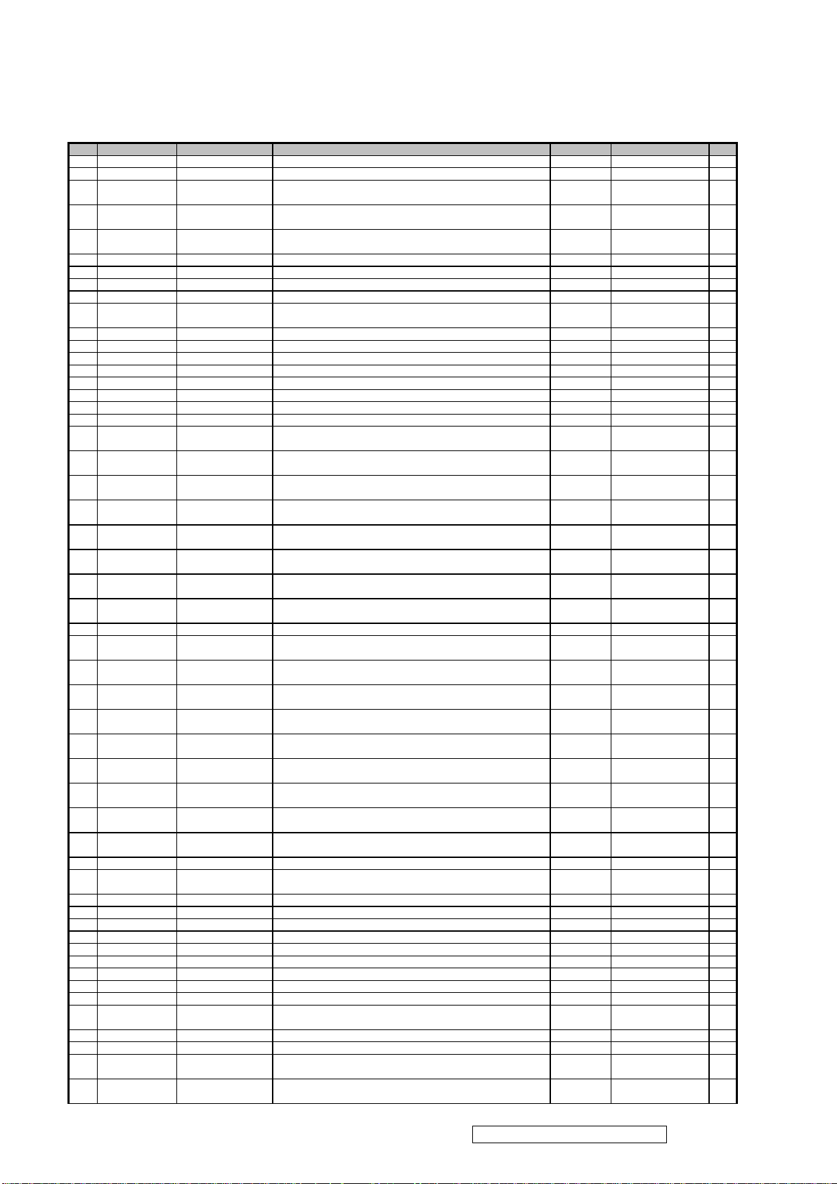
Serial No. Prefix: PQU
Protector Film _Metal-Rear,PC,t=0.254mm,A190E2
Stand-Off 4 #-40*11.8
Hole, for B Grade
Olympic,19",ID BOM,D-sub+Audio,Japan,Silver Black,For VSC,
Olympic,19",ID BOM,D-sub+Audio,UK,Silver Black,For VSC
Rear Assy,A190E2-H06,ASSY,J91A11B5 Black,Fuking
Cover Hinge Assy,A190E2-H06,ASSY,J91A11B5 Black,Fuking
PCBA For A190E2-T,A190E2-H-K,Rev.02,Rigid,203-01,(ODM)
Checksum(6B),DVI Port
(ISP(02AB) , HiLo(148E)), RSDS,Analog+Audio
BOM LIST (VA912-2)
ViewSonic Model Number: VS10696-2E
Rev: 1b
Item ViewSonic P/N Ref. P/N Description Location Universal number# Q'ty
1 E-00002443 MJ0E301K01 19" common BOM,19E3 cell,COF,normal A/C grade 1
2 #N/A L3J003XXXX LCD Panel , For 19.0" LCM, SXGA Common 1
3 #N/A 7414119003
4 #N/A 7414119004
5 #N/A 73-C000047
6 #N/A 36-D001339 Driver IC,Scan,A170E1,HX8633CPD400,256Channel Common 36X8607401/7403 10
7 #N/A 7344191017 ACF,AC-4251FY-16,100M/RL Common 1
8 #N/A 36X8002661 COF,Data,Himax:HX8002KCB66,A190E2 Common 10
9 #N/A 35A19X0202 PCBA For A190E2-H,A190E2-H-X,X2,Rigid,201-02 Common 1
10 #N/A 73-D002676
11 #N/A 7349951002 Silicone,TORAY/-9187L,330g Common 1
12 #N/A PJ0EFT3G03 Olympic,19",Function BOM,D-sub+Audio,Genesis,For VSC 1
13 #N/A 7341991010
14 CB-00000582 3241902003 FFC_X, A190E2,45PIN,60x23mm,PITCH=0.5mm Common 1
15 M-00000559 42A9940007
16 HW-00000553 42A9930008 Screw,M3*P0.5*4,f5.5*2,Steel Common 1
17 B-00000573 2714000022 DC/AC Inverter,TWS-444-983,4.8,mA,2900 V,Sumida Common 2714000023 1
18 M-00000599 44A1913004 Backlight Unit,Direct Type,W/ West Lamp,A190E2 Common 44A1913005/06 1
19 B-00003502 35-D000873
20 #N/A 41-D002122
21 #N/A 41-D002123
22 #N/A PJ0EAAD000(A26)
#N/A PJ0EACF000(C26)
#N/A PJ0EAEG000(E26)
#N/A PJ0EAJF000(J26)
#N/A PJ0EAKF000(K26)
23 CB-00000544 32F2818004 Audio Cable,A150X2,18AWG,180cm,Black,JCE Common 32F2818011 1
24 A-00000458 32E1818015
25 A-00002058 32E1818013
26 A-00002059 32E1818018
27 A-00002060 32E1818014
28 A-00002057 32E1818060
Polarizer,CF,344.1*276.5*0.245,135°,Sumitomo:SQ-W862AP6AG6+SWV,M170E3 Common 7414119001 1
Polarizer,TFT,340.6*273*0.245,135°,Sumitomo:SQW862APK+SWV,M170E3 Common 7414119002 1
ACF,COG,AC-8405Z-23 1.5mmX100M,100000 mmx1.5 mm,Hitachi
Chemical,COG-ACF Common 7344191016 3
ACF,PCB,AC-9825R-35,100000 mmx1.5 mm,Hitachi
Chemical,PCB-ACF Common 7344191004 1
Common 1
Common 1
PCBA for ,A190E2-T,A190E2-H-S,203-04,Rev.02,OSE/USI,ODM
Common 35-D002922 1
Cover AD Assy,A190E2,SECC,CLT ME,t=0.6mm,W/O DVI-D
Common 41A1999107 1
Metal Frame Front Assy,A190E2,SECC,CLT ME,t=0.6mm,for B
Grade Common 41A1969107 1
Olympic,19",Accessory BOM,D-sub+Audio,USA/Taiwan 3
pin,Black,For VSC 1
Olympic,19",Accessory BOM,D-sub+Audio,China 3 pin,Black,For
VSC
Olympic,19",Accessory BOM,D-sub+Audio,European / Korea 2
pin,Black,For VSC
Olympic,19",Accessory BOM,D-sub+Audio,Japan 2 pin,Black,For
VSC
Olympic,19",Accessory BOM,D-sub+Audio,UK / HK 3 pin,Black,For
VSC
Power Code ,UL ,SVT#18/3C ,75C ,LP-30B+LS-13 ,L=1830+/50mm ,Black ,Linetek ,18AWG ,No Bag A26 32E1818019 1
Power Cord ,CCC ,300/500V ,0.75mm2 ,3C ,PC-323+COC-01
,L=1830+/-50mm ,Black ,Linetek ,18AWG ,No Bag C26 32E1818021 1
Power Code ,CEE ,SP-023+IS-14 ,H05VV-F ,3G ,0.75mm2 ,CT-12
,L=1800+/-50mm ,I-SHENG ,18AWG ,Black ,No Bag E.K26 32E1818016 1
Power Code ,JIS ,VCTF ,0.75mm2 ,3C ,LP54+LS-13J ,L=1830+/50mm ,Black ,Linetek ,18AWG ,No Bag J26 32E1818017 1
Power Cord ,BSI ,H05VV-F ,0.75mm2 ,3C ,LP-60L+LS-60
,L=1830+/-50mm ,Black ,18AWG ,PSB Mark ,Linetek ,No Bag K26 32E1818020 1
29 A-00000570 271906519H Adapter,UP06511190-08B,19 V,3.42 A,65 W,Black,Potrans,Two BC C.J26 27-D002151 1
30 A-00000570 27-D003385 Adapter,UP06511190,19 V,3.42 A,65 W,Black,Potrans,NEW LOGO A.E.K26 1
31 #N/A 32-D002132
32 #N/A PJ0EI2620B(A26)
33 HW-00000557 42A9930017 Screw,f3*P1.27*8,f5.5*2,Steel Common 1
34 C-00002368 40-D000249
35 HW-00000556 42A9990005 Screw,M3*P1.27*12,f5.5*2,Steel Common 1
36 HW-00000555 42A9930014 Screw,M3*P0.5*6,Steel Common 1
37 CB-00000583 3241900003 FFC-OSD,A190E2-H01,15Pin,90mm*14mm,Pitch=1.0mm Common 1
38 C-00002369 40-D000242 Stand Seat Assy,A190E2-H06,ASSY,J91A11B5 Black,Fuking A.C.E.J.K26 1
39 C-00002367 40-D000244
40 HW-00002442 42-D000314
41 B-00000575 35A19K0202
42 C-00002365 40-D000246 Bezel Assy,A190E2-H06,ASSY,Pantone 877C silver,Fuking A.C.E.J.K26 1
43 #N/A 10-D001077
44 #N/A 10-D001706
#N/A PJ0EI26202(C26) Olympic,19",ID BOM,D-sub+Audio,China,Silver Black,For VSC,
#N/A PJ0EI26201(E26) Olympic,19",ID BOM,D-sub+Audio,European,Silver Black,For VSC,
#N/A PJ0EI26204(J26)
#N/A PJ0EI26203(K26)
ViewSonic Corporation Confidential - Do Not Copy VA912-2
Accessory Cable,D-Sub,JV-4777,Black,Pins-Pins,Jhen
Vei,30AWG,Reduce Shield Rate Common 32F3018003/4/7 1
Olympic,19",ID BOM,D-sub+Audio,USA,Silver Black,VSC,(For
USA use) 1
A.C.E.J.K26 1
A.C.E.J.K26 1
SCREW,M4,P=0.7 mm,L=15 mm,Special Thin Head,Phillips Cross
Recess ,Screw_with_Washer,SHYE CHING SCREW Common 1
Common 1
Software (EDID_DVI), A190E2, Ver.VSCCF1BD01, ViewSonic,
Common 1
Software (BIOS), A190E2, Ver.19E2TG3002, ViewSonic, Checksum
Common 1
59
Page 63
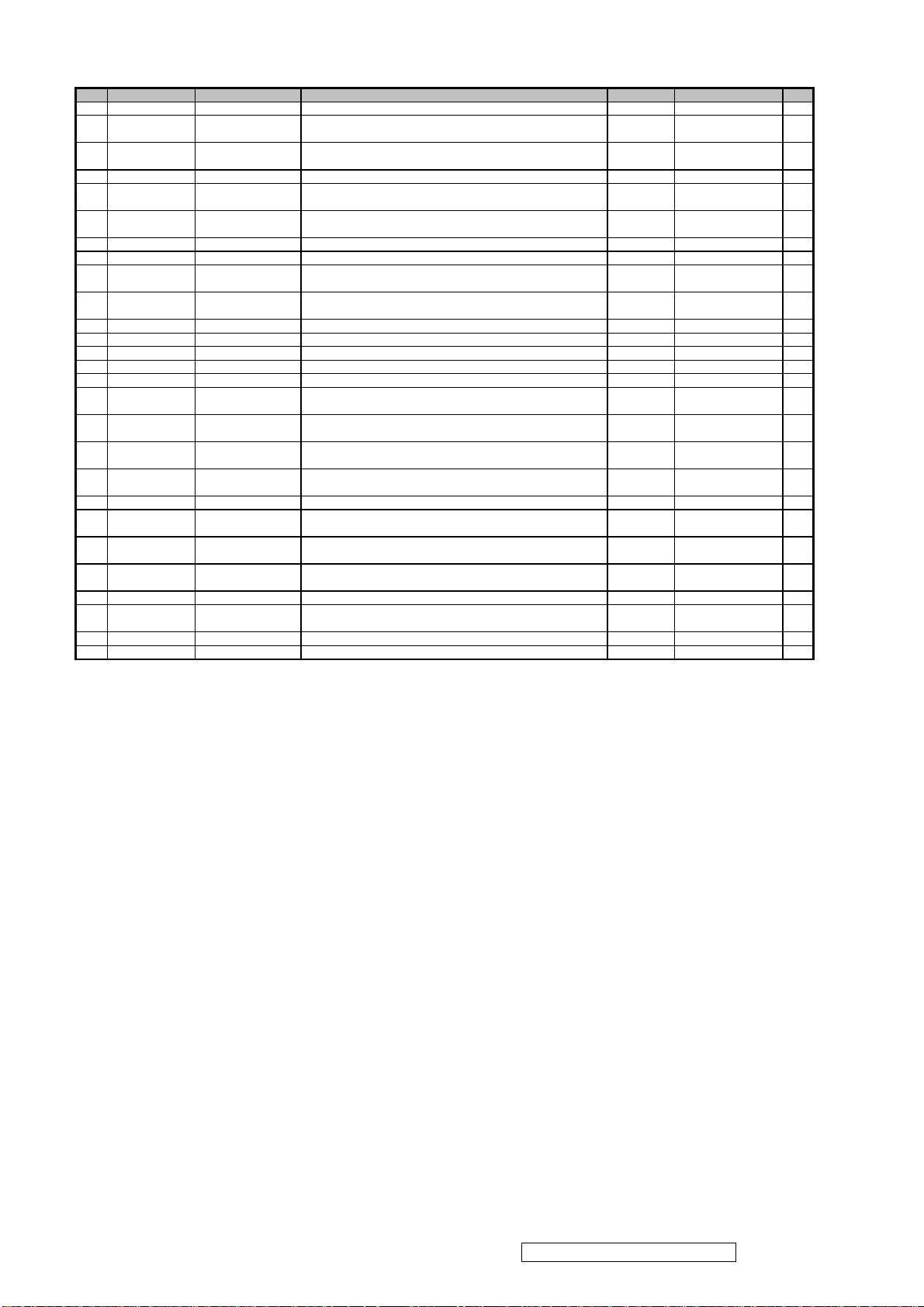
Item ViewSonic P/N Ref. P/N Description Location Universal number# Q'ty
Label,Bar-Code Labe,55*13mm
MM
Bag,700 mmx500 mmx0.13 mm,LDPE,500,Huang Jyii
mm,Hua Sun Paper
Printing,A190E2-H06
71
#N/A
77-D000118
Customer Label,A170E1-H0G,130 mm,80 mm
C26
1
45 DC-00002073 7741519181
46 P-00002378 73-D001222
47 DC-00005072 77-D001649
48 #N/A 77-D000268 SN Label for ,A190E2-H06,50 mmx25 mm,VSC_VA912 A.E.J.K26 1
Panel Protector Film,A190E2-H06,mylar,Just Enter,400X325X0.1
Safety Label for ,A190E2-H06,120 mmx50 mm,Chang
Huang,VSC_VA912 Common 1
Common 1
Common 1
49 #N/A 77-D000359 SN Label for ,A190E2-H06,50 mmx20 mm,VSC_VA912_for China C26 1
50 P-00002070 78-D000337
51 DC-00000586 7741999141 Label,Pallet Barcode Label,75x40,A190E2-H03,VSC Common 1
52 DC-00002370 77-D000121 Carton Label Label,A190E2-H06,76.2 mm,76.2 mm A.C.E.J26 1
53 #N/A 77-D000576
54 #N/A 77-D002835
55 #N/A 77-D003829 Carton Label for ,A190E2-H06,20 mmx20 mm,Chang K26 1
56 M-00000592 7841995111 Separator, 1130x955x11,A190E1-H01 Common 1
57 M-00000560 7345511002 Tape,Security Tape,OPP,L900xW50x0.045mm,VSC Common 1
58 #N/A 73-D001327 Tape,82296 mmx48 mmx0.045 mm,cmo,OPP Common 1
59 P-00002374 7841919941
60 #N/A 78-D001494
61 DC-00002430 76-D001517
62 DC-00002429 76-D001516
63 #N/A 76-D003125
64 #N/A 7841599161 Corner Protector,50*50*1780 Common 1
65 P-00002375 78-D001778
66 P-00005077 78-D001869
67 #N/A 78-D001873
68 #N/A 78-D000275 Warranty Card,A170E1-H0G,143 mmx210 mm,VSC_VA712 C26 1
69 #N/A 77-D001323
70 #N/A 77-D000114 Customer Label,A170E1-H0G,180 mm,100 mm C26 1
Inner Box,A170E1-H0G,454 mmx160 mmx43 mm,Yuen Foong
Yu,Inner Box Common 1
Carton Label for ,A190E2-H06,20 mmx20 mm,Chang
Huang,VSC_VA912_for Europe A.C.E.J26 1
Carton Label for ,A190E2-H06,76.2 mmx76.2 mm,Chang
Huang,VSC_VA912-2U K26 1
Common 1
Pallet,A190E1-H01,Wooden,(KD-HT),1150 mmx970 mmx135
Common 1
MENU for VSC_VA912b_Analog+Caution Card_for
USA,Complex,4C ,Yi-Ching Special Printing,A190E2-H06 A26 1
MENU for VSC_VA912_Analog,Complex,4C,Yi-Ching Special
C.J26 1
MENU for VSC_VA912-2,Paper,1C,Yi-Ching Special
Printing,A190E2-H06 E.K26 1
Carton,A190E2-H06,480 mmx220 mmx524 mm,Chen Ti
Paper,VSC_VA912 Common 1
Cushion,A190E2-H06,EPE,White,488 mmx211 mmx60 mm,Hwa
Chang,PE_Foam (Left) V 2 Common 1
Cushion,A190E2-H06,EPE,White,488 mmx211 mmx60 mm,Hwa
Chang,PE_Foam(Right) V 2 Common 1
Customer Label for ,A170E1-H0G,15 mmx15 mm,Chang Huang ,QC
Pass Label_VSC_for China C26 1
ViewSonic Corporation Confidential - Do Not Copy VA912-2
60
Page 64
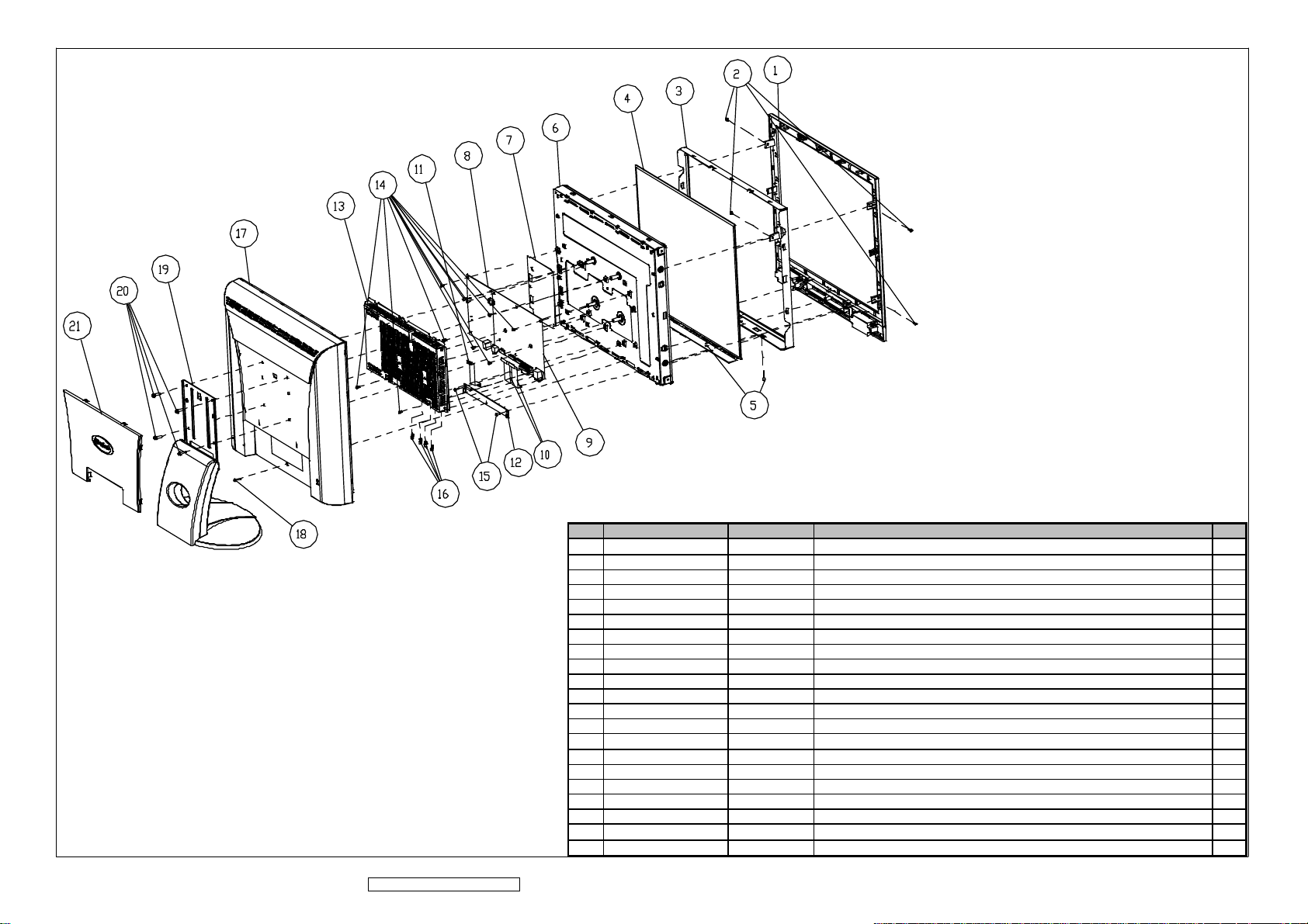
8. Schematic Diagrams
EXPLODED PARTS LIST (VA912-2)
ViewSonic Model Number: VS10696-2E
Rev: 1b
Serial No. Prefix: PQU
Item ViewSonic P/N Ref. P/N Description Q'ty
1 C-00002365 40-D000246 Bezel Assy,A190E2-H06,ASSY,Pantone 877C silver 1
2 HW-00000555 42A9930014 Screw,M3*P0.5*6,f5.3*2.3,Steel 4
3 #N/A 41-D002123 Metal Frame Front Assy,A190E2,SECC,t=0.6mm,for B Grade 1
4 #N/A L3J003XXXX LCD Panel , For 19.0" LCM, SXGA 1
5 HW-00000553 42A9930008 Screw,M3*P0.5*4,f5.5*2,Steel 2
6 M-00000599 44A1913004 Backlight Unit,Direct Type,W/ West Lamp,A190E2 1
7 P-00002378 73-D001222 Panel Protector Film,A190E2-H06,mylar),400X325X0.1 MM 1
8 #N/A 2714000022 DC/AC Inverter,TWS-444-983,4.8,mA,2900 V 1
9 B-00003502 35-D000873 PCBA for ,A190E2-T,A190E2-H-S,203-04,Rev.02,ODM 1
10 #N/A 3241902003 FFC_X, A190E2,45PIN,60x23mm,PITCH=0.5mm 2
11 #N/A 3241900003 FFC-OSD,A190E2-H01,15Pin,90mm*14mm,Pitch=1.0mm 1
12 B-00003502 35-D000873 PCBA for ,A190E2-T,A190E2-H-S,203-04,Rev.02,ODM 1
13 #N/A 41-D002122 Cover AD Assy,A190E2,SECC,t=0.6mm,W/O DVI-D Hole, for B Grade 1
14 HW-00000553 42A9930008 Screw,M3*P0.5*4,f5.5*2,Steel 10
15 HW-00000557 42A9930017 Screw,f3*P1.27*8,f5.5*2,Steel 2
16 M-00000559 42A9940007 Stand-Off 4 #-40*11.8 4
17 C-00002368 40-D000249 Rear Assy,A190E2-H06,ASSY,J91A11B5 Black 1
18 HW-00000556 42A9990005 Screw D3*12L 1
19 C-00002369 40-D000242 Stand Seat Assy,A190E2-H06,ASSY,J91A11B5 Black 1
20 HW-00002442 42-D000314 Screw M4*15L 4
21 C-00002367 40-D000244 Cover Hinge Assy,A190E2-H06,ASSY,J91A11B5 Black 1
ViewSonic Corporation Confidential - Do Not Copy VA912-2
61
Page 65

9. Block Diagram
Audio In
D-sub
Analog Video
Speaker
Audio Out
Main Board
OSD Key Pad
3.3V
LCD Module
Signal
DC -19V
DC/DC
DC-19V
Inverter
Backlight
ViewSonic Corporation Confidential - Do Not Copy VA912-2
62
Page 66
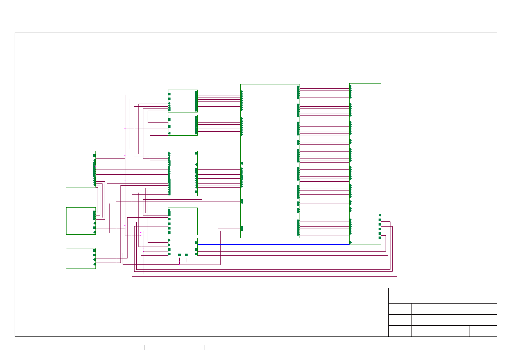
10. Schematic Diagrams
B7
OSD
LED_OR
LED_GR
SOURCE_SELECT
MENU
KEY_DOWN
KEY_UP
AUTO_ADJ
PWR_SW
AUDIO/LAUDIO/L+
AUDIO/R-
AUDIO/R+
AUDIO/R+
AUDIO/RAUDIO/L+
AUDIO/L-
AUDIO
AUDIO_ON
VOL_ADJ
B8
B9
INVERTER I/F
VIN_19V
INV_ON/OFF
INV_ADJ
V33C
B10
B1
B2
V5A
ST_DET1
V5A_ESD
VGH
VGL
VAA
VGA_5V
DDC_CLK
DDC_DAT
ST_DET1
V5A_ESD
B3
V5A_ESD
V5A
ST_DET2
B4
DDC_CLK
DDC_DAT
ST_DET1
ST_DET2
LED_OR
LED_GR
SOURCE_SELECT
MENU
KEY_DOWN
KEY_UP
AUTO_ADJ
PWR_SW
V5A
AUDIO_ON
INV_ON/OFF
DCDC_ON/OFF
PANEL_ON/OFF
VCM_PWM
XAO
B5
DCDC_ON/OFF
V19V
VIN_19V
VGH
VGL
VAA
V5A
PANEL_ON/OFF
VCM_PWM
VAA
V5A
POWER
DDC_CLK
DDC_DAT
V5A
V5A
VIN_19V
INV_ADJ
LED_OR
LED_GR
SOURCE_SELECT
MENU
KEY_DOWN
KEY_UP
AUTO_ADJ
PWR_SW
V5A
AUDIO_ON
INV_ON/OFF
DCDC_ON/OFF
PANEL_ON/OFF
VCM_PWM
XAO
V5A
VGA
DVI
V33C
GNDR
GNDG
GNDB
HSYNC
VSYNC
VGA_5V
MCU
ST_DET2
HWRESET
DC/DC
GMA[1..10]
V25C
CLK+
RIN
GIN
SOG
BIN
R+
R-
G+
G-
B+
B-
CLK-
CSZ
SCL
SDA
INT
AD0
AD3
AD1
AD2
V19V
B6
VCM
V33P
RIN
GNDR
GIN
GNDG
SOG
BIN
GNDB
HSYNC
VSYNC
R+
RG+
GB+
BCLK+
CLK-
ST_DET2
CSZ
SCL EG0P
SDA
HWRESET
INT
AD0
AD3
AD1
AD2
GMA[1..10]
VCM
V33P
V25C
V33C
RIN
GNDR
GIN
GNDG
SOG
BIN
GNDB
HSYNC
VSYNC
R+
RG+
GB+
BCLK+
CLK-
ST_DET2
CSZ
SCL
SDA
HWRESET
INT
AD0
AD3
AD1
AD2
INV_ADJ
VOL_ADJ
V25C
V33C
SCALER
OR0N
OR0P
OR1N
OR1P
OR2N
OR2P
OG0N
OG0P
OG1N
OG1P
OG2N
OG2P
OB0N
OB0P
OB1N
OB1P
OB2N
OB2P
OCLKP
OCLKN
ER0N
ER0P
ER1N
ER1P
ER2N
ER2P
EG0N
EG0P
EG1N
EG1P
EG2N
EG2P
EB0N
EB0P
EB1N
EB1P
EB2N
EB2P
ECLKP
ECLKN
ESTH
OSTH
GVON
GVOFF
STB
POL
STV
CKV
OE
OR0N
OR0P
OR1N
OR1P
OR2N
OR2P
OG0N
OG0P
OG1N
OG1P
OG2N
OG2P
OB0N
OB0P
OB1N
OB1P
OB2N
OB2P
OCLKP
OCLKN
ER0N
ER0P
ER1N
ER1P
ER2N
ER2P
EG0N
EG1N
EG1P
EG2N
EG2P
EB0N
EB0P
EB1N
EB1P
EB2N
EB2P
ECLKP
ECLKN
ESTH
OSTH
STB
POL
STV
CKV
OE
GVON
GVOFF
PANEL_INTERFACE
OR0N
OR0P
OR1N
OR1P
OR2N
OR2P
OG0N
OG0P
OG1N
OG1P
OG2N
OG2P
OB0N
OB0P
OB1N
OB1P
OB2N
OB2P
OCLKP
OCLKN
ER0N
ER0P
ER1N
ER1P
ER2N
ER2P
EG0N
EG0P
EG1N
EG1P
EG2N
EG2P
EB0N
EB0P
EB1N
EB1P
EB2N
EB2P
ECLKP
ECLKN
ESTH
OSTH
STB
POL
STV
CKV
OE
GVON
GVOFF
GMA[1..10]
XAO
VGH
VGL
VAA
VCM
V33P
ViewSonic Corporation Confidential - Do Not Copy VA912-2
63
ViewSonic Corporation
Model
Title
Date Rev:
TOP
Page 67
AU5V1AU5V1
1
AUDIO IN JACK
J1
J1
3
2
1
Place near J1 Jack
VOL_ADJ
AUDIO_ON
ON
0V
AUD_G1AUD_G1
3.3V
L22L22
1 2
1
GND_POWER
3.3V
C134C134
GND_POWER GND_POWER GND_POWER
GND_POWER
BV6W
VOL_ADJ1VOL_ADJ1
1
32
VOL_ADJ
1
GND_POWER
R158R158
OV
AUDIO_ON
ON/OFF1ON/OFF1
1
L21L21
1 2
1 2
L31L31
C132C132
C135C135
C133C133
Low Frequency input -6db point at 241HZ
VOL1VOL1
V19V
R191R191
GND_POWER
1
C144C144
GND_POWER
R168R168
R171R171
C156C156
R192R192
R151R151
Q12
Q12
R165R165
1
GND_POWER
BV6W
R172R172
R155R155
R156R156
32
Q13Q13
BV6W
R189R189
R190R190
R141R141
R142R142
C141C141
C145C145
BV6W
R160R160
R163R163
GND_POWER
BV6W BV6W
GND_POWER
1
Q21Q21
3 2
AUD_R
AUD_L
AUD_R
AUD_L
MODE_SELECT
GND_POWER
R166R166
VOL_MUTE
R169R169
AUD_R1AUD_R1
1
AUD_L1AUD_L1
1
R173R173
R174R174
MODE_SELECT
VOL_MUTE
SHUTDOWN
GAIN_SELECT
BV6W
R161R161
GAIN_SELECT
R164R164
MODE SELECT :H
GAIN SELECT :H
R170R170
GND_POWER
V5A
W6B
GND_POWER
R145R145
HP_DETECT
C154C154
R146R146
GND_POWER
C155C155
R150R150
MODE SELECT :H
GAIN SELECT :H
R167R167
SHUTDOWN
SHUTDOWN : L
VOL_MUTE: MCU CONTROL
GND_POWER
L20L20
1 2
C146C146
GND_POWER
U16U16
21
HP Sense
7
DC Vol
13
Left Dock
12
Left In
11
Beep In
10
Right In
9
Right Dock
4
Mode
5
Mute
2
Shutdown
3
Gain Select
22
Bypass
+
C130+C130
GND_POWER
GND
GND_PAD
1
29
BV6W
C131C131
BV6W
C138C138
C137C137
C136C136
6
27
16
VDD
VDD
VDD
Left Out +
Left Out -
Left Gain 2
Left Gain 1
Right Out +
Right Out -
Right Gain 2
Right Gain 1
GND
GND
GND
GND
8
14
20
23
15
17
18
19
28
26
25
24
GND_POWER
R147R147
R152R152
C139C139
R148R148
C142C142
R153R153
C140C140
R149R149
C143C143
R154R154
L+1L+1
1
L-1L-1
1
R+1R+1
1
R-1R-1
1
AUDIO/L+
AUDIO/L-
AUDIO/R+
AUDIO/R-
AUDIO/L+
AUDIO/L-
AUDIO/R+
AUDIO/R-
ViewSonic Corporation
Model
Title
Date Rev:
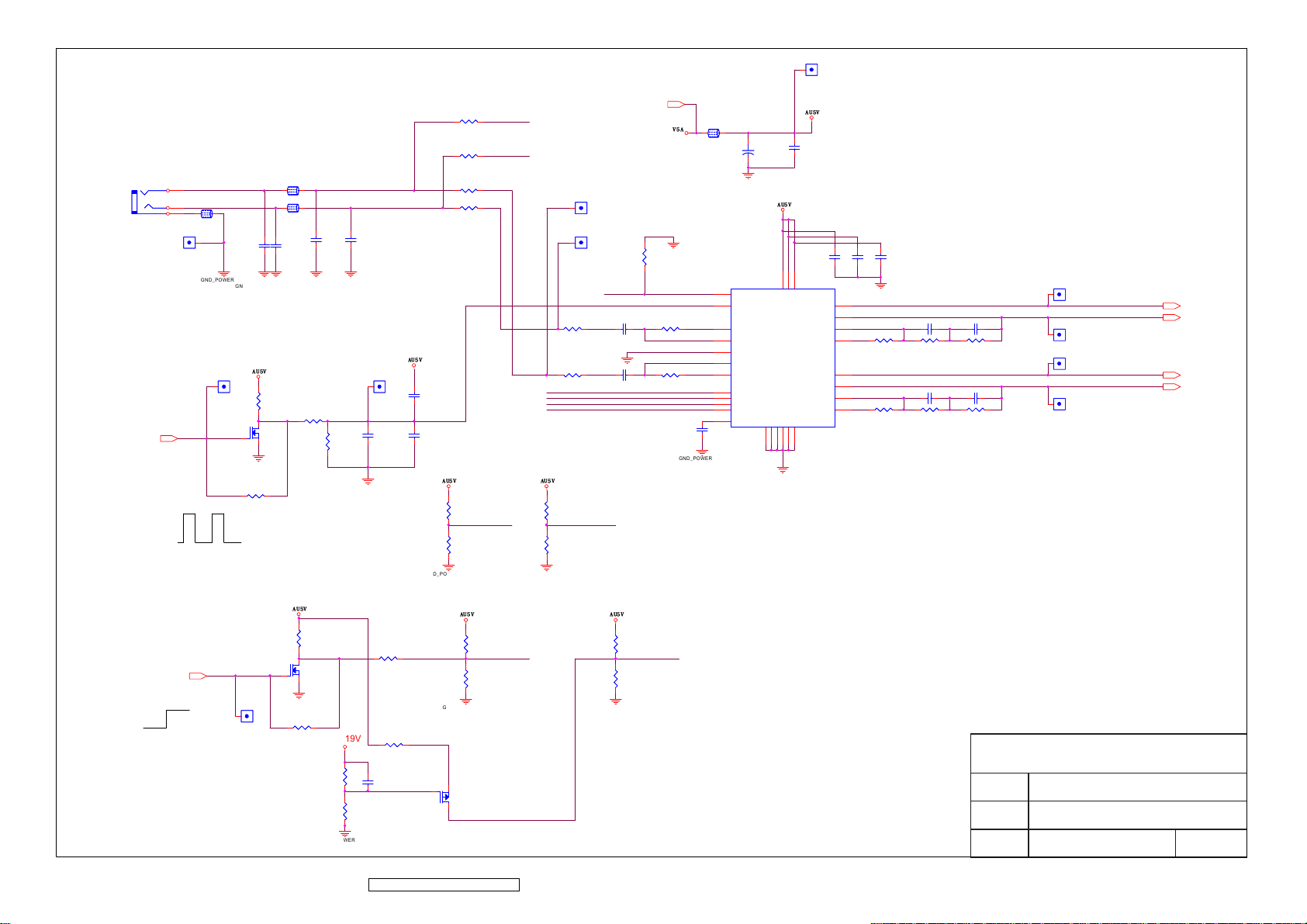
AUDIO
ViewSonic Corporation Confidential - Do Not Copy VA912-2
64
Page 68
CON1
CON1
RGB GND
HSYNC
VSYNC
SYNC GND
DDC SCL
DDC SDA
1/3shield
2/4shield
0/5shield
clk shield
DAT0+
DAT0-
DAT1+
DAT1-
DAT2+
DAT2-
DAT3+
DAT3-
DAT4+
DAT4-
DAT5+
DAT5-
+5V
HPD
clk+
clk-
R
G
B
25
26
27
29
28
8
15
6
7
14
16
11
3
19
22
18
17
10
9
2
1
13
12
5
4
21
20
23
24
GND_POWER
V5A_ESD
R5
R5
R6
R6
V5A
R17
R17
1
R11
R11
V5A
R12
R12
R18
R18
32
D14
D14
32
1
R8
3
D13
D13
R8
2
8
7
6
5
R7
R7
D4
D4
1 2
D9
D9
32
1
R13
R13
32
D5
D5
D10
D10
1 2
D8
D8
U2
U2
R15
R15
1
2
3
4
GND_POWER
D12
D12
32
1 2
R14
R14
32
D11
D11
1
1
D7
D7
NC
NC
NC
GND
1
VCC
VCLK
SCL
SDA
R16
R16
32
1
V5A_ESD
C163C163
GND_POWER
R19
R19
D15
D15
1
ST_DET2
R9
R9
32
R20
R20
1
D16
D16
R10
R10
R+
RG+
GB+
BCLK+
CLK-
L7
V5A V5A_ESD
ViewSonic Corporation Confidential - Do Not Copy VA912-2
L7
D17D17
C39C39
GND_POWER
65
C31C31
C32C32
C33C33
GND_POWER
C34C34
C35C35
C36C36
C37C37
C38C38
ViewSonic Corporation
Model
Title
Date Rev:
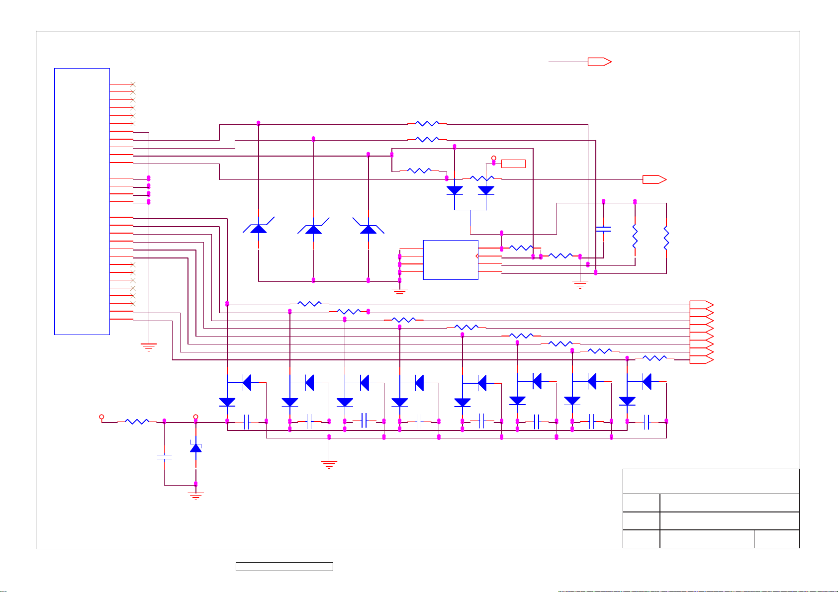
DVI INTERFACE
Page 69
INV_ADJ
ST_DET2
R194
R194
RIN
GNDR
GIN
GNDG
SOG
BIN
GNDB
HSYNC
VSYNC
R+
RG+
GB+
BCLK+
CLK-
CSZ
SCL
SDA
HWRESET
INT
AD0
AD3
AD1
AD2
VOL_ADJ
RIN
GNDR
GIN
GNDG
SOG
BIN
GNDB
HSYNC
VSYNC
R1
R1
VDVI
C22C22
Y1Y1
C23C23
GND_POWER
GND_POWER
طޏ
11/19 V5A V33C
R+
RG+
GB+
BCLK+
CLK-
C6C6
CSZ
SCL
SDA
HWRESET
INT
AD0
AD3
AD1
AD2
C24C24
R2
R2
R3
R3
V33C
VDPLLVPLLVAD VPO VDDVDVI
65
55
AVDD
AVDD
AVSS
64
56
35
AVDD_MPLL
AVSS
AVSS
AVSS_MPLL
68
36
R138
R138
51
45
AVDD_DVI
AVDD_DVI
AVSS_PLL
54
53
AVDD_PLL
AVSS_DVI
AVSS_DVI
42
39
94
84
21
11
VDDP
VDDP
VDDP
VDDP
AVSS_DVI
GNDP
GNDP
48
20
10
GND_POWER
104
85
114
VDDP
GNDP
95
126
VDDP
GNDP
105
117
97
87
18
VDDP
VDDC
VDDC
VDDC
DDC1_DAT/GPO7
DDC1_CLK/GPO8
GNDP
GNDC
GNDP
GNDP
86
19
127
115
VDDC
CLKAP
CLKAN
CLKBP
CLKBN
GNDC
RA1P
RA1N
RA2P
RA2N
RA3P
RA3N
GA1P
GA1N
GA2P
GA2N
GA3P
GA3N
BA1P
BA1N
BA2P
BA2N
BA3P
BA3N
RB1P
RB1N
RB2P
RB2N
RB3P
RB3N
GB1P
GB1N
GB2P
GB2N
GB3P
GB3N
BB1P
BB1N
BB2P
BB2N
BB3P
BB3N
GPO0
GPO1
GPO2
GPO3
GPO4
96
ESP
OSP
GNDC
116
NC
NC
NC
NC
NC
GNDC
106
107
108
OR2P
109
OR2N
110
OR1P
111
112
OR1N
OR0P
113
OR0N
98
OG2P
99
OG2N
100
OG1P
101
102
OG1N
OG0P
103
OG0N
88
OB2P
89
90
OB2N
OB1P
91
OB1N
92
OB0P
93
118
OB0N
119
OCLKP
OCLKN
16
ER2P
17
ER2N
22
ER1P
23
24
ER1N
ER0P
25
ER0N
7
8
9
EG2P
EG2N
12
13
EG1P
EG1N
14
15
EG0P
EG0N
122
123
124
125
EB2P
EB2N
128
1
EB1P
4
EB1N
5
EB0P
120
EB0N
121
ECLKP
ECLKN
75
76
ESTH
OSTH
83
82
81
STB
80
STV
79
CKV
28
OE
29
GVOFF
GVON1
POL1
OR2P
OR2N
OR1P
OR1N
OR0P
OR0N
OG2P
OG2N
OG1P
OG1N
OG0P
OG0N
OB2P
OB2N
OB1P
OB1N
OB0P
OB0N
OCLKP
OCLKN
ER2P
ER2N
ER1P
ER1N
ER0P
ER0N
EG2P
EG2N
EG1P
EG1N
EG0P
EG0N
EB2P
EB2N
EB1P
EB1N
EB0P
EB0N
ECLKP
ECLKN
ESTH
OSTH
STB
STV
CKV
OE
GVOFF
R185
R185
R186
R186
R187
R187
R188
R188
POL
GVON
GVON
POL
V33C VAD
L1L1
2
1
L2L2
1
V33C VDVI
L3L3
2
1
V33C
L4L4
2
1
C1C1
VPLLV33C
2
D1D1
GND_POWER
VDPLL
C12C12
GND_POWER
C2C2
GND_POWER
C4C4
C5C5
GND_POWER
C7C7
C13C13
C3C3
C8C8
C10C10
C9C9
U1
U1
63
RIN0
62
RIN0M
60
GIN0
59
GIN0M
61
SOGIN0
58
BIN0
57
BIN0M
37
HSYNC0
38
VSYNC0
40
R+
41
R-
43
G+
44
G-
46
B+
47
B-
49
CK+
50
CK-
52
REXT
66
REFP
C11C11
67
REFM
69
ALE/CSZ
71
RDZ/SCL
70
WRZ/SDA
32
HWRESETZ
72
INT
30
AD0/GPO6
31
AD3/GPO5
77
AD1/EINV
78
AD2/OINV
73
PWM0
74
PWM1
33
XIN
34
XOUT
3
BYPASS
2
AVSS_LPLL
6
BUSTYPE
VDDV25C
V25C
ViewSonic Corporation Confidential - Do Not Copy VA912-2
C25C25 C27C27
C26C26
GND_POWER GND_POWER
66
C29C29
C28C28
L6L6
2
1
V33C
V33C
1
L5L5
VPO
2
C14C14
C15C15
C17C17
C16C16
C19C19
C21C21
C20C20C18C18
ViewSonic Corporation
Model
Title
Date Rev:
SCALER
Page 70
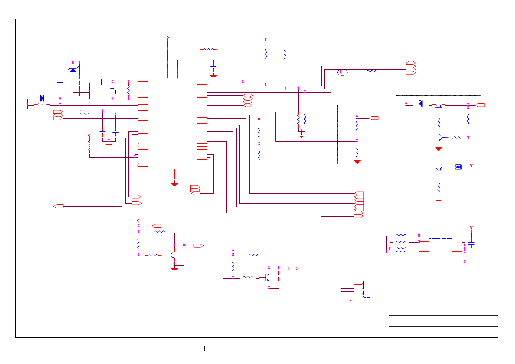
GND_POWER
D18
D18
1
DDC_CLK
DDC_DAT
VCM_PWM
R25
R25
INT
VCPU
R22
R22
R139
AD0
AD1
AD2
AD3
V5A
1
R139
R33
R33
R37
R37
GND_POWER
3
Q7Q7
2
GND_POWER
R140
R140
R29
R29
R28
R28
GND_POWER
PANEL_ON/OFF
(PANEL POWER CONTROL)
C50C50
LED
GND_POWER
DDC_DAT
DDC_CLK
GND_POWER
C44C44
VCPU
R23
R23
03/08/04
V19V
R32
R32
R36
R36
GND_POWER
MENU
KEY_DOWN
KEY_UP
SOURCE_SELECT
AUTO_ADJ
PWR_SW
LED_GR
LED_OR
CN8
CN8
SDA
SCL
CSZ
HWRESET
VCPU
2
1
2
3
GND_POWER
3
Q3Q3
U4
U4
8
VCC
7
WP
6
SCL
5
SDA
Q1Q1
1
R31
R31
3
Q2Q2
1
2
2
1
R42
R42
GND_POWER
A0
A1
A2
GND
R34
R34
L8L8
2
1
1
2
3
4
D19
D19
V19V
R44
R44
R46
R46
R47
R47
SCL1
R48
R48
SDA1
1
2
3
4
ViewSonic Corporation
Model
MCU
R30
R30
5V_ON/OFF
V5A
V5A
C48C48
GND_POWER
VGA_5V
10/20
17
P1.0
18
P1.1
20
P1.2
21
P1.3
22
P1.4
23
P1.5
24
P1.6
25
P1.7
3
2
1
42
41
40
34
27
26
16
9
30
31
32
33
DCDC_ON/OFF
C49C49
03/08/04
5V_ON/OFF
C40C40
GND_POWER
V5A
R51
R51
R52
R52
R50
R50
03/08/04
2
ZDP7
ZDP7
U3
U3
8
V5A
1
4
VDD
VDD3
AD2/P6.2/HLFHI
DA10/P6.4
DA11/P6.5
DA12/P6.6
DA13/P6.7
VSS
10
GND_POWER
ST_DET1
ST_DET2
INV_ON/OFF
3
Q6Q6
2
GND_POWER
DA0/P5.0
DA1/P5.1
DA2/P5.2
DA3/P5.3
DA4/P5.4
DA5/P5.5
DA6/P5.6
AD0/P6.0
AD1/P6.1
AD3/P6.3
1
GND_POWER
R26
R26
R27
R27
C41C41
V5A
Avoid entering the
self-test mode of the
MCU.
C43C43
2
SDA1
SCL1
R35
R35
C42C42
Y2Y2
C45C45
C46C46
GND_POWER
R24
R24
C47C47
LED
V5A
11
X2
12
X1
7
RST
29
HSCL/P3.0/RX
28
HSDA/P3.1/TX
19
P3.2/INT0
13
ISDA/P3.4/T0
14
ISCL/P3.5/T1
36
VBLANK/P4.0
37
HBLANK/P4.1
15
STOUT/P4.2
43
HSYNC
44
VSYNC
35
DA7/HCLAMP
39
HLFHO/DA8
38
HALFV/DA9
5
NC
6
NC
MTV312M
AUDIO_ON
XAO
R43
R43
R45
R45
R49
R49
ViewSonic Corporation Confidential - Do Not Copy VA912-2
67
Title
Date Rev:
Page 71
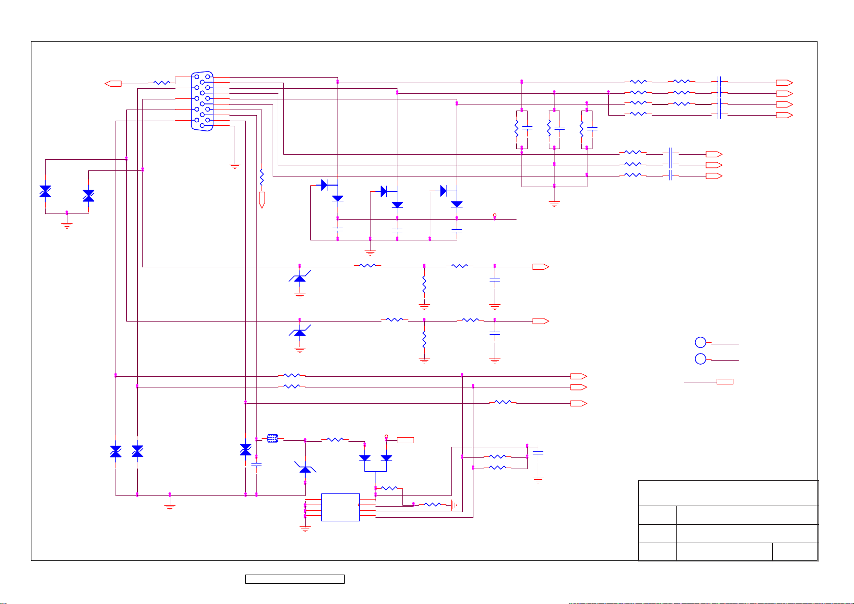
DDC_DAT
D22
D22
0603/10p/varistor/OPEN
0603/10p/varistor/OPEN
0603/10p/varistor/OPEN
0603/10p/varistor/OPEN
GND_POWER
D23
D23
R109
R109
OPEN
OPEN
CLK_DDC
DAT_DDC
11
12
13
14
15
CN7
CN7
MLX89263-6762
MLX89263-6762
1
6
2
7
3
8
4
9
5
10
GND_POWER
VSI
R122
R122
OPEN
OPEN
DDC_CLK
1
0603/100n/25V/Y/RoHS
0603/100n/25V/Y/RoHS
2
D32
D32
UDZSF-5.6B/PbF
UDZSF-5.6B/PbF
1
GND_POWER
2
D33
D33
UDZSF-5.6B/PbF
UDZSF-5.6B/PbF
1
GND_POWER
R130
R130
0603/100R/5%/PbF
0603/100R/5%/PbF
R131
R131
0603/100R/5%/PbF
0603/100R/5%/PbF
3
D24
D24
BAV99/RoHS
BAV99/RoHS
2
C157
C157
0603/0R/5%/RoHS
0603/0R/5%/RoHS
3
1
2
0603/100n/25V/Y/RoHS
0603/100n/25V/Y/RoHS
GND_POWER
R124
R124
0603/0R/5%/RoHS
0603/0R/5%/RoHS
0603/75R/5%/PbF
0603/75R/5%/PbF
3
1
D25
D25
BAV99/RoHS
BAV99/RoHS
C158
C158
R127
R127
GND_POWER GND_POWER
D26
D26
BAV99/RoHS
BAV99/RoHS
2
0603/100n/25V/Y/RoHS
0603/100n/25V/Y/RoHS
Most of Customers Recommended.
0603/100R/5%/PbF
0603/100R/5%/PbF
R126
R126
0603/2.2K/5%/RoHS
0603/2.2K/5%/RoHS
0603/100R/5%/PbF
0603/100R/5%/PbF
R129
R129
0603/2.2K/5%/RoHS
0603/2.2K/5%/RoHS
(0603/100)
V5A_ESD GND_POWER
C159
C159
R125
R125
R128
R128
R117
R117
C120
C120
OPEN
OPEN
C126
C126
0603/33p/50V/N
0603/33p/50V/N
GND_POWERGND_POWER
C127
C127
0603/220p/50V/N
0603/220p/50V/N
R132
R132
0603/100R/5%/PbF
0603/100R/5%/PbF
R118
R118
0603/75R/5%/PbF
0603/75R/5%/PbF
HSYNC
VSYNC
C121
C121
OPEN
OPEN
R119
R119
C122
C122
OPEN
OPEN
0603/75R/5%/PbF
0603/75R/5%/PbF
DDC_CLK
DDC_DAT
ST_DET1
R1110603/68R/1%/PbF
R1110603/68R/1%/PbF
R113 0603/68R/1%/PbF
R113 0603/68R/1%/PbF
R115
R115
0603/68R/1%/PbF
0603/68R/1%/PbF
R116 OPEN
R116 OPEN
RD Recommended
R120
R120
0603/100R/5%/PbF
0603/100R/5%/PbF
R121
R121
0603/100R/5%/PbF
0603/100R/5%/PbF
R123
R123
0603/100R/5%/PbF
0603/100R/5%/PbF
12/15/2003
R110
R110
0603/0R/5%/RoHS
0603/0R/5%/RoHS
R112
R112
0603/0R/5%/RoHS
0603/0R/5%/RoHS
R114
R114
0603/0R/5%/RoHS
0603/0R/5%/RoHS
C123
C123
0603/47n/16V/7
0603/47n/16V/7
C124
C124
0603/47n/16V/7
0603/47n/16V/7
C125
C125
0603/47n/16V/7
0603/47n/16V/7
TP
HSYNC1
HSYNC1
TP
VSYNC1
VSYNC1
VGA_5V
GNDR
GNDG
GNDB
1
HSYNC
1
VSYNC
C116
C116
0603/47n/16V/7
0603/47n/16V/7
C117
C117
0603/47n/16V/7
0603/47n/16V/7
C118
C118
0603/47n/16V/7
0603/47n/16V/7
C119
C119
OPEN/0603/1n/50V/7
OPEN/0603/1n/50V/7
VGA_5V
RIN
GIN
BIN
SOG
L19
L19
2
1
BK1608LL121/PbF
D27
D29
D28
D28
0603/22p/varistor
0603/22p/varistor
D29
0603/22p/varistor
0603/22p/varistor
GND_POWER
12/15/2003
ViewSonic Corporation Confidential - Do Not Copy VA912-2
D27
0603/22p/varistor
0603/22p/varistor
68
BK1608LL121/PbF
03/08/04
C129
C129
0603/100n/25V/Y/RoHS
0603/100n/25V/Y/RoHS
0603/10R/5%/PbF
0603/10R/5%/PbF
2
D30
D30
UDZSF-5.6B/PbF
UDZSF-5.6B/PbF
1
U15
U15
1
NC
2
NC
3
NC
4
GND
S-24CS02AFT-TB-G
S-24CS02AFT-TB-G
GND_POWER
R133
R133
03/08/04
VCC
VCLK
SCL
SDA
VGA_5V
V5A
2
1
3
8
7
6
5
V5A
D31
D31
BAV70W/PbF
BAV70W/PbF
R136
R136
0603/3.9K/5%/PbF
0603/3.9K/5%/PbF
VGA_5V
0603/47K/5%/RoHS
0603/47K/5%/RoHS
GND_POWER
R137
R137
R134
R134
0603/10K/5%/RoHS
0603/10K/5%/RoHS
R135
R135
0603/10K/5%/RoHS
0603/10K/5%/RoHS
C128
C128
OPEN/0603/100n/25V/Y/RoHS
OPEN/0603/100n/25V/Y/RoHS
GND_POWER
ViewSonic Corporation
Model
Title
Date Rev:
VGA
Page 72
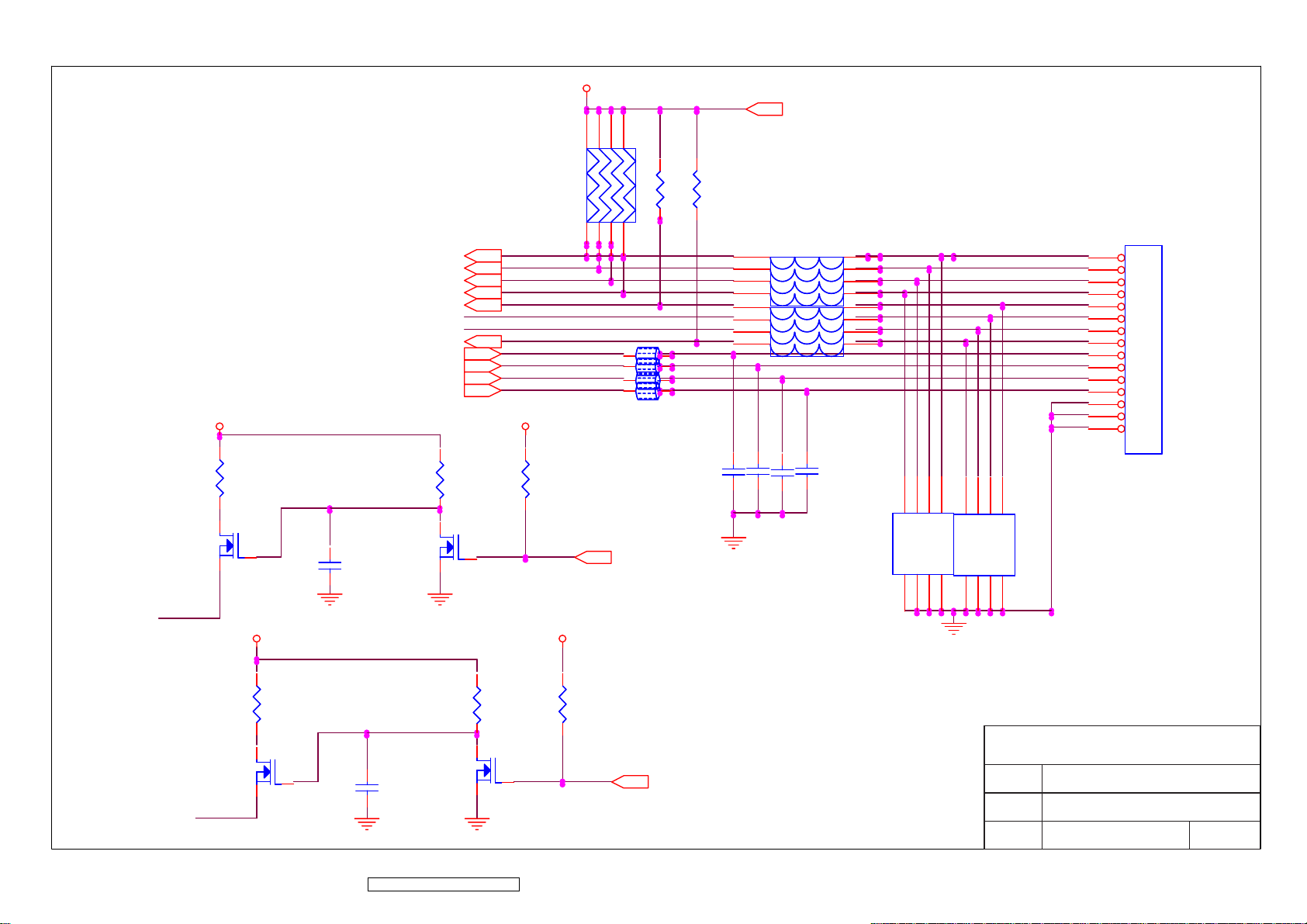
V5A
MENU
KEY_DOWN
KEY_UP
SOURCE_SELECT
AUTO_ADJ
PWR_SW
AUDIO/R+
AUDIO/RAUDIO/L+
AUDIO/L-
LED_G
LED_O
V5A
RP46
RP46
V5A
V5A
7
8
5
6
R53
R53
3
1
2
4
L26L26
1
L27L27
1
L28L28
1
L29L29
1
R54
R54
CN3
CN3
5
6
7
8
5
6
7
2
2
2
2
8
4L
4L
4L
4L
4
3
2
1
4
3
2
1
15
14
13
12
11
10
9
8
7
6
5
4
3
2
1
R179
R179
32
Q14
Q14
1
LED_O
V5A
R182
R182
32
Q16
Q16
1
LED_G
ViewSonic Corporation Confidential - Do Not Copy VA912-2
C160C160
C161C161
69
32
R180
R180
Q15
Q15
1
R183
R183
32
Q17
Q17
R181
R181
V5A
R184
R184
1
LED_OR
LED_GR
C151C151
C150C150
GND_POWER
C152C152
C153C153
CP33
CP33
1
2
3
4
A
B
C
D
CA
CA
D
C
B
A
5
6
7
8
1
2
3
4
A
B
C
D
CA
CA
D
C
B
A
5
6
7
8
GND_POWER
CP34
CP34
ViewSonic Corporation
Model
Title
Date Rev:
OSD INTERFACE
Page 73
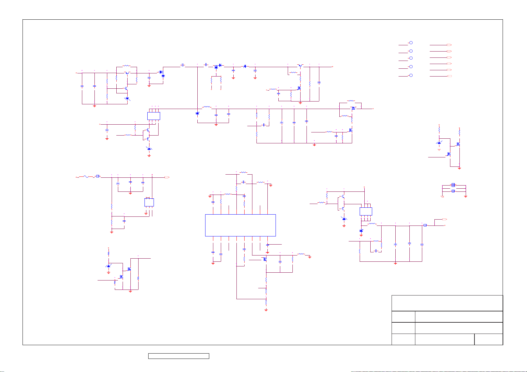
Power Sequence : 5V -> VL -> VH & AVDD
-5.5V
VGL
CP8CP8
CP7CP7
GND_POWER
V19V
GND_POWER
VIN_19V
LP3LP3
FP1FP1
1
(High --> Enable)
2
ZDP6
ZDP6
GND_POWER
DCDC_ON/OFF
RP6
RP6
RP11
RP11
CP35+CP35
+
GND_POWER
V19V
RP37RP37
1 2
1 2
1 2
RP32
RP32
RP33
RP33
PANEL_ONB
RP44RP44
VIN_19V1
VIN_19V1
1
TP
VIN_19V
V5A1
V5A1
1
TP
V5A
VAA1
VAA1
1
TP
D2
D2
RP1
RP1
QP2QP2
2
3
RP4
RP4
1
32
1
QP3QP3
12
ZDP2
ZDP2
RP18
RP18
RP22
RP22
OUT2
RP3
RP3
GND_POWER
QP6QP6
1
1
GND_POWER
1
CP5CP5
8
7
6
5
D
D
D
D
S
S
S
G
1
2
3
4
QP7QP7
2 3
QP10QP10
3 2
ZDP4
ZDP4
1 2
V19V
CP19CP19
CP17+CP17
+
GND_POWER
1
32
QP18
QP18
1
GND_POWER
CP20CP20
4
5
6
QP13QP13
E2
B2
C1
E1
C2
B1
1
3
2
IC_Vcc
GND_POWER
CP23CP23
DC_ON
32
QP16
QP16
RP41RP41
CP1CP1
32
D3
D3
V19V
CP2CP2
2
3
1
1
RP8
RP8
RP7
RP7
VAA V5A
LP2LP2
DP1
DP1
GND_POWER
CP30CP30
GND_POWER
1
CT
VREF
16
IC_VREF
CP10CP10
RP29
RP29
CP22CP22
2
RT
SCP
15
CP31CP31
1 2
ZDP1
ZDP1
2
CP3CP3
GND_POWER GND_POWER
CP11CP11
RP24
RP24
IC_VREF
CP18CP18
RP26
RP26
RP27
RP27
NON1
5
3
4
FB1
INV1
NON1
NON2
INV2
FB2
14
13
12
NON2
DC_ON
RP39
RP39
Pin 2, 3 change
each other
1
CP4CP4
RP10
RP10
VAA
CP9CP9
RP14
RP14
RP15
RP15
8
9
3 2
GND_POWER
GND
VCC
CP27CP27
GND_POWER
QP17
QP17
RP42
RP42
RP43
RP43
RP45
RP45
+
UP1
UP1
IC_Vcc
CP32CP32
CP15CP15
NON2
RP21
RP21
RP25
RP25
CP21CP21
RP31
RP31
OUT1
6
7
DT1
OUT1
OUT2
DT2
10
11
OUT2
CP28CP28
1
PANEL_ONB
IC_VREF
QP1QP1
2
3
1
RP2
RP2
RP5
RP5
32
QP4
QP4
1
RP12
RP12
GND_POWER
CP12+CP12
CP13CP13
11/24
RP38
RP38
RP40
RP40
GND_POWER
CP14CP14
DCDC_ON/OFF
OUT1
RP9
RP9
GND_POWER
23V
VGH
CP6CP6
RP13
RP13
QP5
QP5
2
3
13V
4
G
D
5
1 2
GND_POWER
RP36
RP36
VAA
V19V
1
2
3
QP14QP14
S
S
S
D
D
D
8
7
6
LP7LP7
DP2
DP2
RP34
RP34
CP29CP29
1
RP16
RP16
RP17
RP17
1
1
1
RP23
RP23
2 3
3 2
1 2
GND_POWER
32
QP8
QP8
1
QP12QP12
QP15QP15
ZDP5
ZDP5
NON1
RP19
RP19
CP16CP16
RP28
RP28
RP30
RP30
VAA
VGH1
VGH1
1
TP
VGH
VGL1
VGL1
1
VGL
TP
CP24+CP24
+
RP35
RP35
CP25CP25
GND_POWERGND_POWER
VIN_19V
VIN_19V
V5A
VAA
VGH
VGL
DCDC_ON/OFF
V19V
ZDP3
ZDP3
1 2
DCDC_ON/OFF
[INV_GND]
LP10LP10
2
1
VGH
RP20
RP20
12
R4
R4
32
QP9
QP9
1
32
QP11
QP11
1
GND_POWER
LP4LP4
LP5LP5
2
1
2
1
LP6LP6
2
1
GND_POWER
V5A
V5A
5.0V
CP26CP26
ViewSonic Corporation
GND_POWER
Model
Title
DC
ViewSonic Corporation Confidential - Do Not Copy VA912-2
70
Date Rev:
Page 74
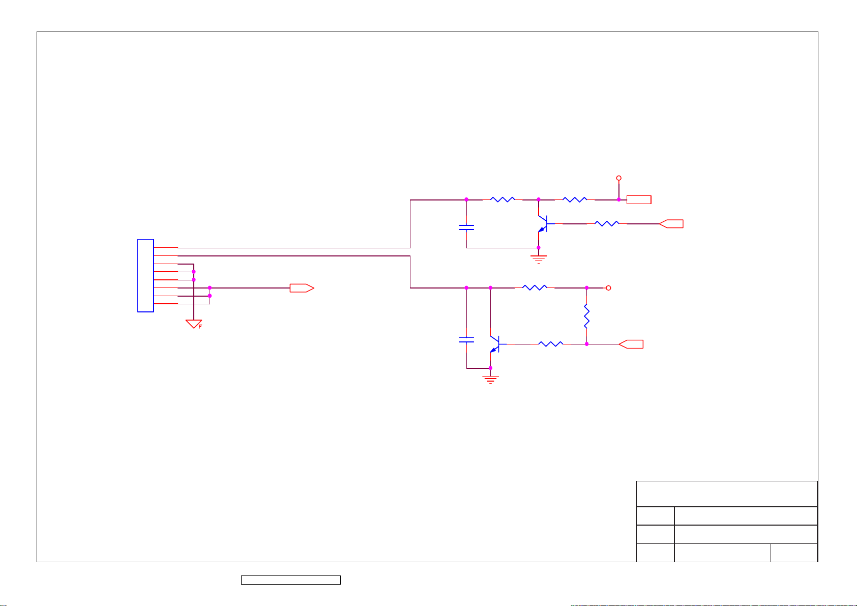
CN2
CN2
R199
R199
V33C
V33C
INV_ADJ
V33C
INV_ON/OFF
R195
R195
R196
R196
R197
R197
1
C30C30
1
2
3
4
5
6
7
8
GND_INV
VIN_19V
C162C162
R198
R198
1
Q19Q19
2 3
GND_POWER
R200
R200
Q18Q18
2 3
GND_POWER
ViewSonic Corporation Confidential - Do Not Copy VA912-2
71
ViewSonic Corporation
Model
Title
Date Rev:
INVERTER I/F
Page 75
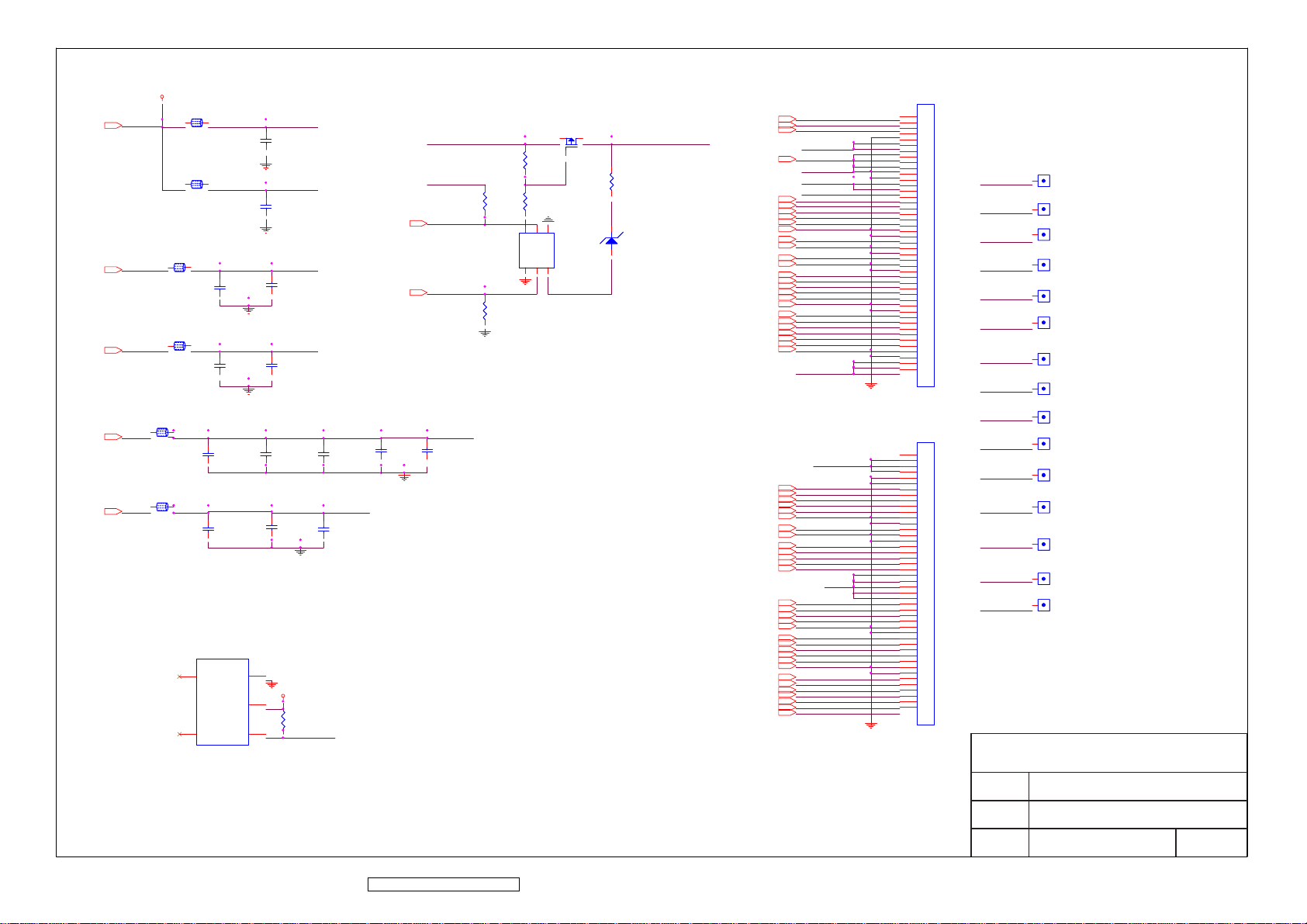
V33P
V33B
VGH_P
VGD
GVON
GVOFF
VCOM
(3-STEP)
R55
R55
R57
R57
R58
R58
5
6
A_D
B_G
A_S
A_G
1
R59
R59
GND_POWER
2
GND_POWER
2
GND_POWER
4
B_S
B_D
Q9
Q9
3
Q8
Q8
3
1
R56
R56
ZD1
ZD1
1 2
PANEL_VGH
L9L9
2
1
L10L10
2
1
L11L11
2
1
VGH
VGH
C53C53
L12L12
2
1
VGL
VGL
C55C55
L13L13
2
1
VCM
VCM
C57C57
L14L14
2
1
VAA
VAA
C62C62
U5
U5
4
VSS
NC
VDD
S809
SEIKO
S809
SEIKO
5
Td
OUT
3
2
1
U5
U5
C51C51
GND_POWER
C52C52
GND_POWER
C54C54
GND_POWER
C56C56
GND_POWER
C58C58
C63C63
GND_POWER
V33B
12
VSD
VGD
VGH_P
PANEL_VGL
R60
R60
GND_POWER
XAO
GVON
GVOFF
C61C61
C59C59
VSA
C64C64
C60C60
GND_POWER
XAO
OE
CKV
STV
OB2P
OB2N
OB1P
OB1N
OB0P
OB0N
OCLKP
OCLKN
OG2P
OG2N
OG1P
OG1N
OG0P
OG0N
OR2P
OR2N
OR1P
OR1N
OR0P
OR0N
OSTH
EB2P
EB2N
EB1P
EB1N
EB0P
EB0N
ECLKP
ECLKN
GMA1
GMA2
GMA3
GMA4
GMA5
GMA6
GMA7
GMA8
GMA9
GMA10
EG2P
EG2N
EG1P
EG1N
EG0P
EG0N
ER2P
ER2N
ER1P
ER1N
ER0P
ER0N
ESTH
VGD
PANEL_VGL
PANEL_VGH
VCOM
OB2P
OB2N
OB1P
OB1N
OB0P
OB0N
POL
STB
POL
STB
OCLKP
OCLKN
OG2P
OG2N
OG1P
OG1N
OG0P
OG0N
OR2P
OR2N
OR1P
OR1N
OR0P
OR0N
OSTH
VSD
GND_POWER
VCOM
EB2P
EB2N
EB1P
EB1N
EB0P
EB0N
ECLKP
ECLKN
GMA1
GMA2
GMA3
GMA4
GMA5
VSA
GMA6
GMA7
GMA8
GMA9
GMA10
EG2P
EG2N
EG1P
EG1N
EG0P
EG0N
ER2P
ER2N
ER1P
ER1N
ER0P
ER0N
ESTH
GND_POWER
CN4
CN4
1
1
2
2
3
3
4
4
5
5
6
6
7
7
8
8
9
9
10
10
11
11
12
12
13
13
14
14
15
15
16
16
17
17
18
18
19
19
20
20
21
21
22
22
23
23
24
24
25
25
26
26
27
27
28
28
29
29
30
30
31
31
32
32
33
33
34
34
35
35
36
36
37
37
38
38
39
39
40
40
41
41
42
42
43
43
44
44
45
45
CN5
CN5
1
1
2
2
3
3
4
4
5
5
6
6
7
7
8
8
9
9
10
10
11
11
12
12
13
13
14
14
15
15
16
16
17
17
18
18
19
19
20
20
21
21
22
22
23
23
24
24
25
25
26
26
27
27
28
28
29
29
30
30
31
31
32
32
33
33
34
34
35
35
36
36
37
37
38
38
39
39
40
40
41
41
42
42
43
43
44
44
45
45
VSD
VSA
VCOM
VGD
PANEL_VGH
PANEL_VGL
STB
POL
ESTH
OSTH
STV
CKV
OE
GVON
GVOFF
1
1
1
1
1
1
1
1
1
1
1
1
1
1
1
VSD1VSD1
VSA1VSA1
VCOM1VCOM1
VGD1VGD1
P_VGH1P_VGH1
P_VGL1P_VGL1
STB1STB1
POL1POL1
ESTH1ESTH1
OSTH1OSTH1
STV1STV1
CKV1CKV1
OE1OE1
GVON1GVON1
GVOFF1GVOFF1
ViewSonic Corporation
ViewSonic Corporation Confidential - Do Not Copy VA912-2
72
Model
PANEL I/F
Title
Date Rev:
Page 76
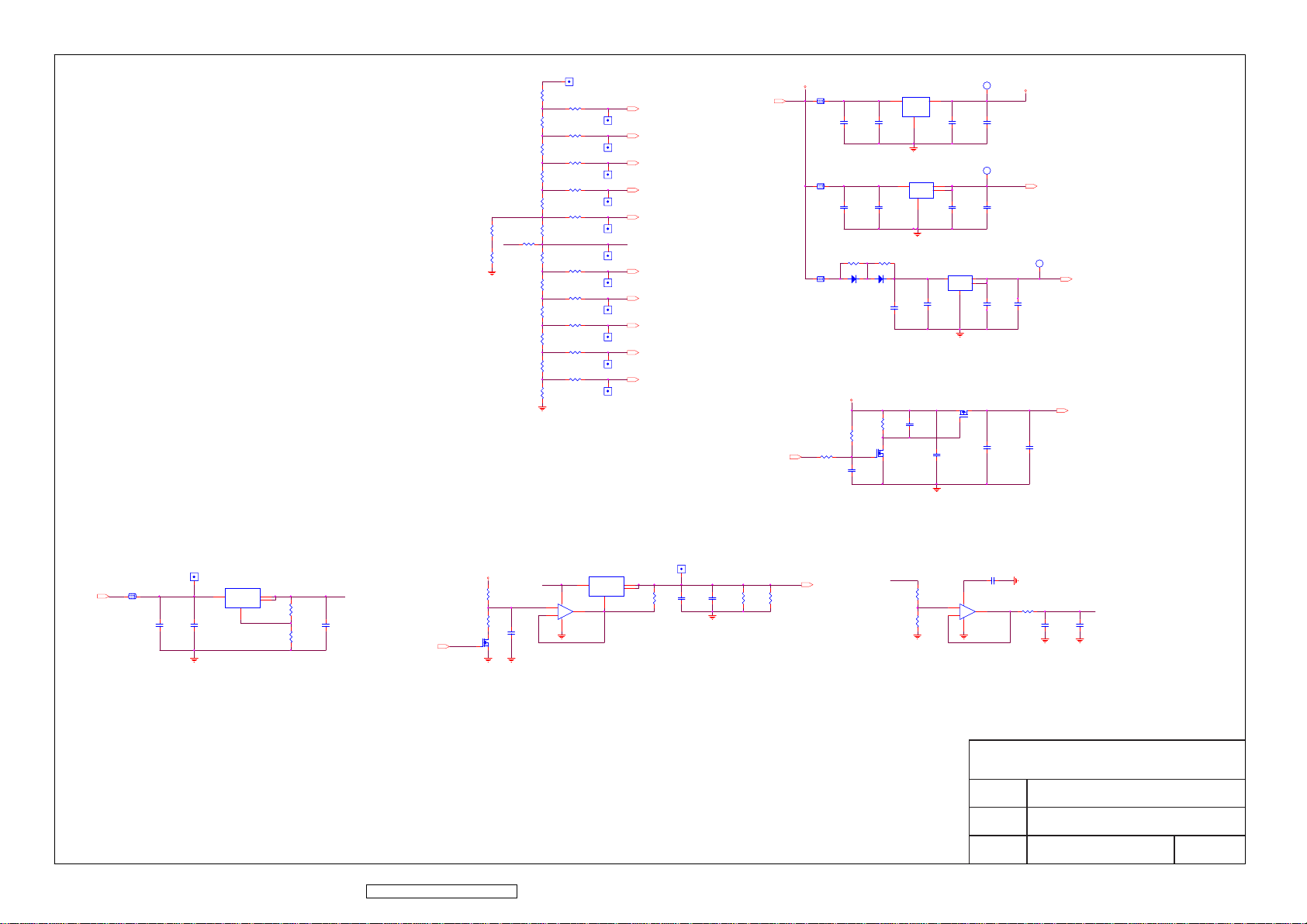
R75R75
R80R80
GND_POWER
VPREF1VPREF1
VPREF
1
R61R61
R64R64
VS1
R65R65
R66R66
VS2
R67R67
R70R70
VS3
R71R71
R72R72
VS4
R73R73
R74R74
VS5
R76R76
R79R79
VPREF
R81R81
R82R82
VS6
R83R83
R86R86
VS7
R87R87
R88R88
VS8
R89R89
R90R90
VS9
R91R91
R92R92
VS10
R93R93
GND_POWER
GMA1
GMA1
1
GMA1GMA1
GMA2
GMA2
1
GMA2GMA2
GMA3
GMA3
1
GMA3GMA3
GMA4
GMA4
1
GMA4GMA4
GMA5
GMA5
1
GMA5GMA5
VCN
1
VCN1VCN1
GMA6
GMA6
1
GMA6GMA6
GMA7
GMA7
1
GMA7GMA7
GMA8
GMA8
1
GMA8GMA8
GMA9
GMA9
1
GMA9GMA9
GMA10
GMA10
1
GMA10GMA10
V5A
PANEL_ON/OFF
V5A
1 2
1 2
1 2
R98R98
L15L15
C70C70
L16L16
C78C78
PP11PP11
D20D20
1 2
L17L17
V33A
U6U6
1
3
Vout
Vin
GND
2
C71C71
GND_POWER
U8U8
3
VOUT2VIN
4
VOUT
GND
1
C79C79
GND_POWER
PP12PP12
D21D21
1 2
C92C92
C91C91
R96R96
R97R97
1
C106C106
C100C100
32
QP19QP19
GND_POWER
V33A1V33A1
TP
V33A
1
(PANEL VCC)
V33A
C73C73
C72C72
V33C1V33C1
TP
1
V33C
V33C
C80C80
U10U10
3
4
IN
OUT
2
OUT
GND
1
GND_POWER
Q10Q10
32
1
C105C105
(SCALER VCC)
C81C81
V25V1V25V1
TP
1
V25C
V25C
(SCALER Core VCC)
C93C93
C94C94
(Panel VCC)
V33P
C103C103
C104C104
L18L18
13.0V
VAA
1 2
VAA
ViewSonic Corporation
VOP1VOP1
U13U13
1
VOP
C111C111
C110C110
GND_POWER
2
3
Vout
Vin
4
Vout
ADJ
1
VPREF
R104R104
C112C112
R108R108
VCM_PWM
47KHz
VCM_PWM
1
GND_POWER
V5A
R99R99
VSCM
R106R106
C115C115
32
Q11Q11
GND_POWER
VOP
3
2
GND_POWER
U12U12
3
Vout2Vin
4
Vout
ADJ
U14A
U14A
1
84
+
+
-
-
VSCM_ADJ
1
VCM1VCM1
1
R101R101
C108C108
C109C109
GND_POWER
VCM
R102R102
VCM
R103R103
R100R100
R107R107
GND_POWER
VSCN
5
6
VOPVPREF
84
+
+
-
-
GND_POWER
C107C107
GND_POWER
U14B
U14B
R105R105
VSCN_OUT
7
VCN
C113C113
C114C114
GND_POWER GND_POWER
ViewSonic Corporation
Model
Title
Date Rev:
73
Confidential - Do Not Copy VA912-2
POWER
Page 77
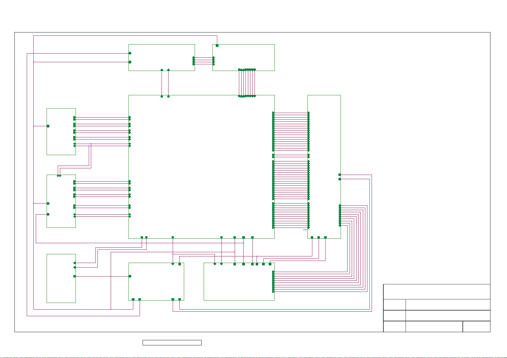
10. Schematic Diagrams
V5A
DVI INPUT
DVI INPUT
DDC_SCL
DDC_SDA
ANALOG INPUT
V5A
V33C
V33C
GRAPHIC INPUT
INV_ON/OFF
INVERTER I/F
INVERTER I/F
RX0+
RX0-
RX1+
RX1-
RX2+
RX2-
RXC+
RXC-
DDC_SDA
DDC_SCL
RED+
RED-
GREEN+
GREEN-
BLUE+
BLUE-
HSYNC
VSYNC
RXD
TXD
INV_ADJ
VIN_19V
VIN_19V
V5A
RX0+
RX0-
RX1+
RX1-
RX2+
RX2-
RXC+
RXC-
DDC_SDA
DDC_SCL
RED+
RED-
GREEN+
GREEN-
BLUE+
BLUE-
HSYNC
VSYNC
RXD
TXD
INV_ON/OFF
INV_ADJ
AUDIO
GM5126
V19V
V5A
RX0+
RX0-
RX1+
RX1-
RX2+
RX2-
RXC+
RXC-
DDC_SDA
DDC_SCL
AUDIO
AUDIO_ON
AUDIO_ON
AUDIO_ON
VOL_ADJ
VOL_ADJ
VOL_ADJ
AUDIO/R+
AUDIO/RAUDIO/L+
AUDIO/L-
OSD INTERFACE
V5A
AUDIO/R+
AUDIO/RAUDIO/L+
AUDIO/L-
OSD
LED_GI
PWR_SW
LED_G
PWR_SW
LED_GI
PWR_SW
LED_OI
LED_O
LED_OI
KEY_UP
MENU
KEY_DOWN
KEY_UP
AUTO_ADJ
KEY_DOWN
MENU
MENU
KEY_UP
KEY_DOWN
SOURCE_SELECT
AUTO_ADJ
SOURCE_SELECT
AUTO_ADJ
SOURCE_SELECT
SCALER
RED+
RED- OG2P
GREEN+
GREEN-
BLUE+
BLUE-
HSYNC
VSYNC
RXD
TXD
PANEL_ON/OFF
PANEL_ON/OFF
VAA
VGL PANEL_ON/OFF
VGH
POWER
VCM_PWM
VCM_PWM
VCM_PWM
PANEL_ON/OFF
POWER
V5A
V25V
V33C
V33C
V25V
V5A
V33C
V25V
VAA
DC/DC
VIN_19V
V5A
INV_ON/OFF
V19V
INV_ADJ
DC/DC
ECLKP
ECLKN
OCLKP
OCLKN
GVOFF
V33B
GMA10
ER0P
ER0N
ER1P
ER1N
ER2P
ER2N
EG0P
EG0N
EG1P
EG1N
EG2P
EG2N
EB0P
EB0N
EB1P
EB1N
EB2P
EB2N
OR0P
OR0N
OR1P
OR1N
OR2P
OR2N
OG0P
OG0N
OG1P
OG1N
OG2N
OB0P
OB0N
OB1P
OB1N
OB2P
OB2N
GVON
CKV
OSTH
ESTH
XAO
GMA1
GMA2
GMA3
GMA4
GMA5
GMA6
GMA7
GMA8
GMA9
PANEL INTERFACE
ER0P
ER0N
ER1P
ER1N
ER2P
ER2N
EG0P
EG0N
EG1P
EG1N
EG2P
EG2N
EB0P
EB0N
EB1P
EB1N
EB2P
EB2N
ECLKP
ECLKN
OR0P
OR0N
OR1P
OR1N
OR2P
OR2N
OG0P
OG0N
OG1P
OG1N
OG2P
OG2N
OB0P
OB0N
OB1P
OB1N
OB2P
OB2N
OCLKP
OCLKN
GVON
GVOFF
OE
STV
POL
STB
OE
STV
POL
STB
CKV
CSTH
ESTH
XAO
VCM
PANEL
ER0P
ER0N
ER1P
ER1N
ER2P
ER2N
EG0P
EG0N
EG1P
EG1N
EG2P
EG2N
EB0P
EB0N
EB1P
EB1N
EB2P
EB2N
ECLKP
ECLKN
OR0P
OR0N
OR1P
OR1N
OR2P
OR2N
OG0P
OG0N
OG1P
OG1N
OG2P
OG2N
OB0P
OB0N
OB1P
OB1N
OB2P
OB2N
OCLKP
OCLKN
GVON
GVOFF
OE
STV
POL
STB
CKV
OSTH
ESTH
XAO
VAA
VGL
VGL
VGH
VGH
GMA10
GMA10
GMA9
GMA9
GMA8
GMA8
GMA7
GMA7
GMA6
GMA6
GMA5
GMA5
GMA4
GMA4
GMA3
GMA3
GMA2
GMA2
GMA1
GMA1
VAA
VCM
V33B
VCM
V33B
ViewSonic Corporation
Model
Main
ViewSonic Corporation Confidential - Do Not Copy VA912-2
74
Title
Date Rev:
Page 78
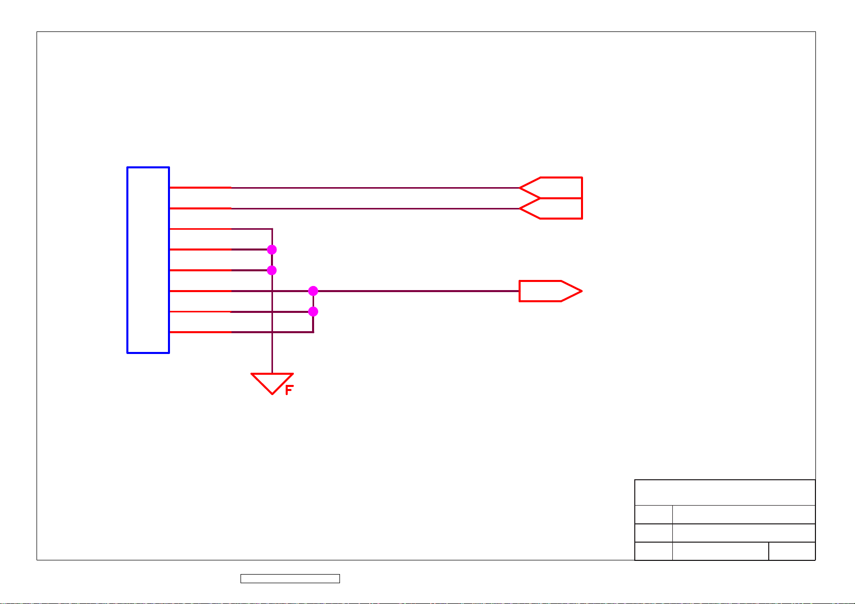
CN1
CN1
1
2
3
4
5
6
7
8
3273-008-10
3273-008-10
INV_ADJ
INV_ADJ
INV_ON/OFF
INV_ON/OFF
VIN_19V
VIN_19V
GND_INV
ViewSonic Corporation Confidential - Do Not Copy VA912-2
75
ViewSonic Corporation
Model
Title
Date Rev:
Inverter I/F
Page 79
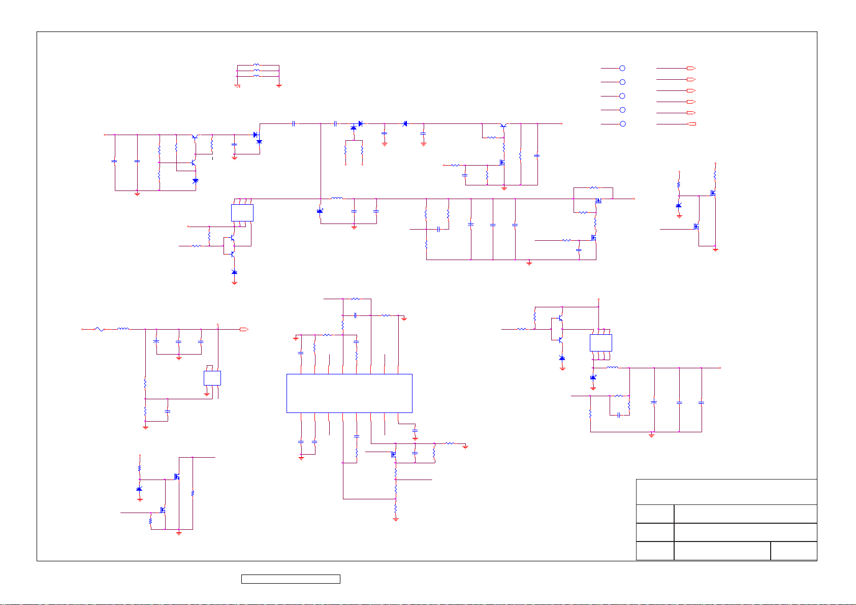
VIN_19V
Power Sequence : 5V -> VL -> VH & AVDD
-5.5V
VGL
CP7CP7
CP8CP8
LP5LP5
FP1FP1
1 2
1 2
2
RP32RP32
1
2
RP33RP33
1
V19V
RP40RP40
PANEL_ONB
2
ZDP6ZDP6
1
PANEL_ON/OFF
(High --> Enable)
RP45RP45
LP1LP1
LP2LP2
LP3LP3
[INV_GND]
CP1CP1
QP2QP2
2 3
RP3RP3
1
RP4RP4
3
QP3QP3
1
V19V
2
1
ZDP2ZDP2
2
RP19RP19
RP22RP22
OUT2
1
1
RP11RP11
V19V
1
CP19CP19
CP18CP18
2
CP23CP23
1
3
QP18QP18
1
2
CP20CP20
564
QP15QP15
321
IC_Vcc
DC_ON
3
QP17QP17
2
RP43RP43
3
1
D2D2
CP5CP5
2
8
5
D6D7D
D
QP7QP7
S1S3S
G
2
4
3
QP9QP9
2
2
QP11QP11
3
2
ZDP4ZDP4
1
V19V
V19V
CP22CP22
1
VREF16SCP15NON2
IC_VREF
CP30CP30
RP28RP28
RT2CT
D1D1
3 2
1
1
RP7RP7
VAA
V5A
LP4LP4
2
DP1DP1
1
RP30RP30
CP31CP31
IC_VREF
NON1
3
14
NON2
CP10CP10
RP24RP24
CP17CP17
RP26RP26
CP21CP21
RP31RP31
5
4
FB1
INV1
NON1
FB2
INV2
12
13
DC_ON
CP29CP29
RP38RP38
ZDP1ZDP1
12
CP3CP3
1
RP8RP8RP6RP6
CP11CP11
RP25RP25
OUT1
6
7
DT1
OUT1
DT2
OUT2
11
10
OUT2
PANEL_ONB
1
CP4CP4
RP10RP10
1
VAA
RP15RP15
RP16RP16
CP15CP15
NON2
RP21RP21
UP1UP1
8
GND
VCC
9
IC_Vcc
CP28CP28
CP32CP32
IC_VREF
RP37RP37
RP39RP39
2
QP16QP16
3
RP41RP41
RP42RP42
RP44RP44
QP1QP1CP2CP2
2 3
1
RP2RP2
1
1
RP5RP5
RP9RP9
3
QP4QP4
1
2
1
RP12RP12
CP9CP9
1
CP12CP12
2
CP14CP14
CP13CP13
RP29
RP29
OUT1
CP6CP6
PANEL_ON/OFF
RP27
RP27
23V
VGH
RP14RP14
RP17RP17
1
RP20RP20
1
1
CP16CP16
3
QP12
QP12
1
2
QP14
QP14
2
1
3
2
ZDP5
ZDP5
1
NON1
VIN_19V1
VIN_19V1
VIN_19V
1
TP
V5A1
V5A1
V5A
1
TP
VAA1
VAA1
VAA
1
TP
VGH1
VGH1
VGH
1
TP
VGL1
VGL1
VGL
1
TP
QP6QP6
4
5
2
1
RP36
RP36
13V
32
1
1
RP18RP18
3
QP10QP10
2
V19V
2
3
1
S
S
S
G
QP13
QP13
D
D
D
D
8
7
6
LP6
LP6
DP2
DP2
RP34
RP34
RP35
RP35
CP27
CP27
VAA
1
2
CP24
CP24
VIN_19V
V5A
VAA
VGH
VGL
PANEL_ON/OFF
PANEL_ON/OFF
V19V
2
1
VIN_19V
V5A
VAA
VGH
VGL
PANEL_ON/OFF
VGH
1
1
5.0V
R32R32
2
3
QP5QP5
1
2
3
QP8QP8
2
V5A
CP26
CP26
RP13RP13
ZDP3ZDP3
CP25
CP25
ViewSonic Corporation
Model
DC
Title
ViewSonic Corporation Confidential - Do Not Copy VA912-2
58
Date Rev:
Page 80
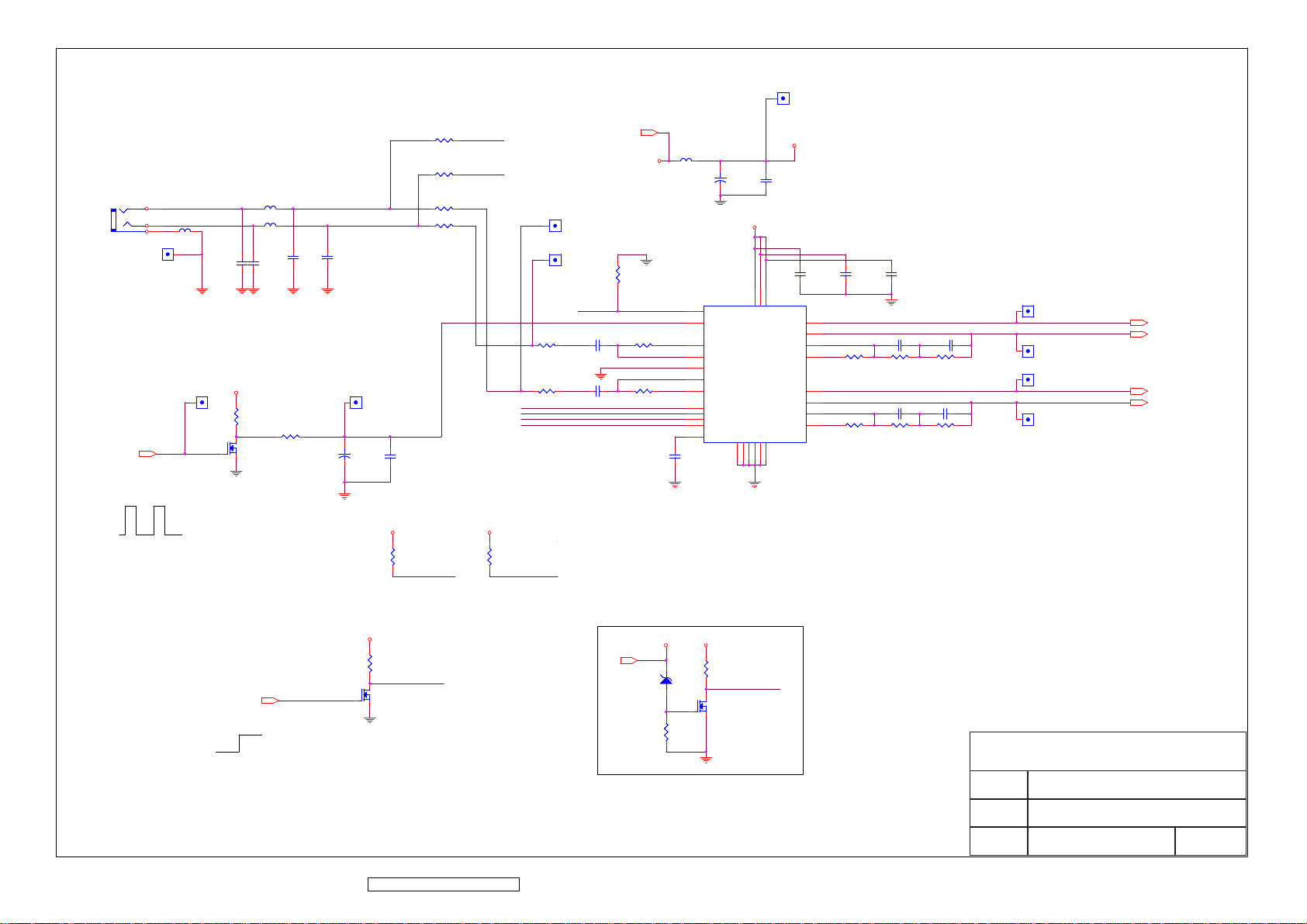
AU5V1AU5V1
1
AUDIO IN JACK
J1J1
3
2
1
Place near J1 Jack
VOL_ADJ
3.3V
AUD_G1AUD_G1
R1R1
R2R2
L2L2
L4L4
1
L3L3
C3C3
C6C6
C5C5
C4C4
R3R3
R4R4
Low Frequency input -6db point at 241HZ
VOL_ADJ1VOL_ADJ1
1
VOL_ADJ
AU5V
R13R13
R17R17
32
Q1Q1
1
VOL1VOL1
1
C17+C17
+
C18C18
AUD_R
AUD_L
AUD_R
AUD_L
AUD_R1AUD_R1
1
AUD_L1AUD_L1
1
R6R6
R11R11
MODE_SELECT
VOL_MUTE
SHUTDOWN
GAIN_SELECT
HP_DETECT
C10C10
C13C13
V5A
L1L1
V5A
C1
+C1+
R5R5
U1U1
21
HP Sense
7
DC Vol
R7R7
R12R12
13
Left Dock
12
Left In
11
Beep In
10
Right In
9
Right Dock
4
Mode
5
Mute
2
Shutdown
3
Gain Select
22
Bypass
GND_PAD
C19C19
29
AU5V
AD5V
C2C2
AU5V
C8C8
C7C7
6
27
16
VDD
VDD
VDD
GND
GND
GND
GND
1
8
14
20
Right Gain 2
Right Gain 1
GND
23
Left Out +
Left Out Left Gain 2
Left Gain 1
Right Out +
Right Out -
15
17
18
19
R8R8
28
26
25
24
R14R14
C9C9
L+1L+1
1
C11C11
R9R9
C15C15
R15R15
C12C12
R10R10
C16C16
R16R16
L-1L-1
1
R+1R+1
1
R-1R-1
1
AUDIO/L+
AUDIO/L-
AUDIO/R+
AUDIO/R-
AUDIO/L+
AUDIO/L-
AUDIO/R+
AUDIO/R-
MODE SELECT :H
GAIN SELECT :H
AU5V
OV
R20R20
MODE_SELECT
AU5V
R21R21
GAIN_SELECT
AU5V
R24R24
VOL_MUTE
32
AUDIO_ON
AUDIO_ON
ON
3.3V
Q2Q2
1
0V
SHUTDOWN : Nomally Low
VOL_MUTE: MCU CONTROL
ViewSonic Corporation Confidential - Do Not Copy VA912-2
77
V19V AU5V
V19V
V19V
R149R149
ZD13ZD13
1 2
1
R151R151
SHUTDOWN
32
Q12Q12
Add new circuit to reduce DC plug out pop noise
ViewSonic Corporation
Model
Title
Date Rev:
AUDIO
Page 81
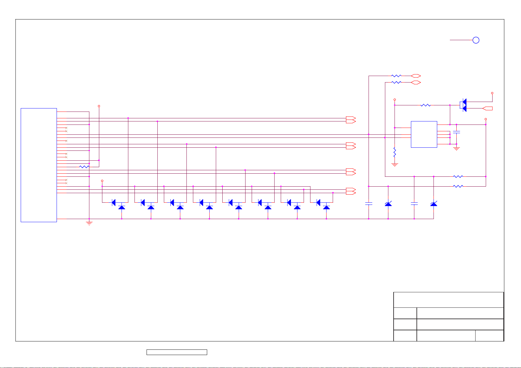
DVI_5V
1
DVI_5V1DVI_5V1
TP
P1P1
SHELL1
DATA2-
DATA2+
DATA2/4_SHLD
DATA4-
DATA4+
DDC_CLK
DDC_DATA
A_VSYNC
DATA1-
DATA1+
DATA1/3_SHLD
DATA3-
DATA3+
GND
H_PLUG_DET
DATA0-
DATA0+
DATA0/5_SHLD
DATA5-
DATA5+
CLK_SHLD
CLK+
CLK-
SHELL2
+5V
R33R33
R34R34
DVI_5V
DVI_5V
31
1
2
3
4
5
DDC_CLK
6
DDC_DAT
7
8
9
10
11
12
13
14
15
R37R37
16
17
18
19
20
21
22
23
24
32
V5A
32
D4D4
1
32
D5D5
1
32
D6D6
1
32
D7D7
1
32
D8D8
1
32
D9D9
1
32
D10D10
1
32
D11D11
1
RX2RX2+
RX1RX1+
RX0-
RX0+
RXC+
RXC-
C21C21
R36R36
ZD1ZD1
1 2
DDC_SCL
DDC_SDA
R35R35
U2U2
7
VCLK
6
SCL
5
SDA
GND
Write protection
C22C22
VCC
NC1
NC2
NC3
DVI_5V
D3D3
DVI_5V
2
3
8
1
2
3
4
R38R38
R39R39
ZD2ZD2
1 2
1
DVI_EDID_5V
C20C20
V5A
DVI_EDID_5V
V5A
ViewSonic Corporation Confidential - Do Not Copy VA912-2
78
ViewSonic Corporation
Model
Title
Date Rev:
DVI Input
Page 82
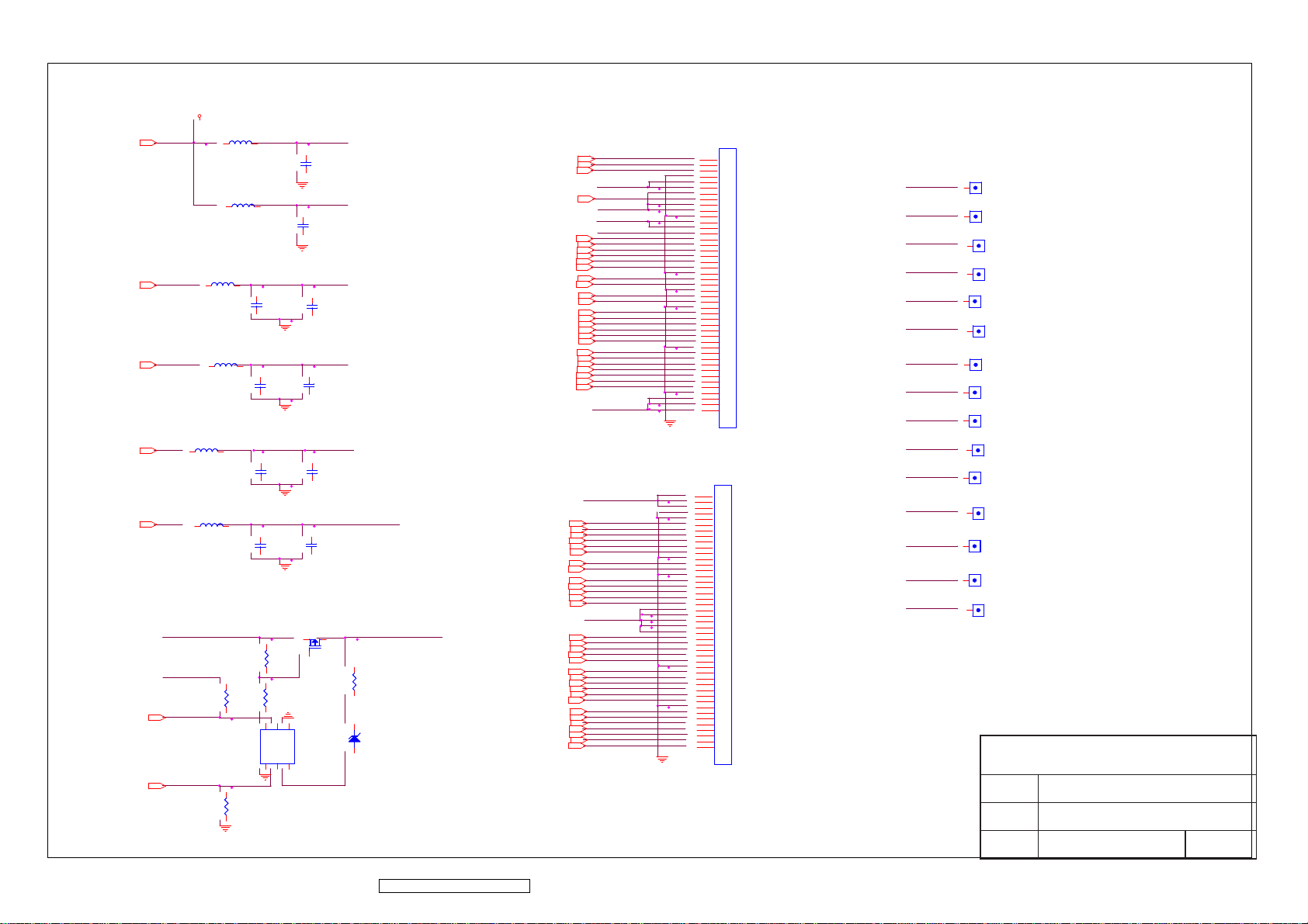
V33B
VGH
VGL
VCM
VAA
GVOFF
GVON
V33B
L8
L8
L9
L9
L10
VGH
VGL
VCM
VAA
L10
C45
C45
L11
L11
C47
C47
L12
L12
C52
C52
L13
L13
C55
C55
(3-STEP)
VGH_P
R59
R59
VGD
R62
R62
R61
R61
GVON
GVOFF
6
A_D
A_S
1
R63
R63
VSD
C43
C43
VGD
C44
C44
VGH_P
C46
C46
PANEL_VGL
C48
C48
VCOM
C53
C53
VSA
C56
C56
Q7
Q7
3
2
1
R60
R60
5
4
Q8
Q8
B_S
B_G
A_G
B_D
2
3
2
1
PANEL_VGH
ZD12
ZD12
OB1P
OCLKN
OCLKP
GMA1
GMA2
GMA3
GMA4
GMA5
GMA6
GMA7
GMA8
GMA9
GMA10
OG0N
OG2P
OSTH
OB0N
OB2N
OG0P
OG1N
OG1P
OR0N
OR0P
OR1P
OR2N
ECLKN
OB0P
OB1N
OB2P
OG2N
OR1N
OR2P
XAO
OE
CKV
STV
EB0N
EB0P
EB1N
EB1P
EB2N
EB2P
ECLKP
EG0N
EG0P
EG1N
EG1P
EG2N
EG2P
ER0N
ER0P
ER1N
ER1P
ER2N
ER2P
ESTH
VGD
PANEL_VGL
PANEL_VGH
VCOM
EB0N
EB0P
EB1N
EB1P
EB2N
EB2P
POL
POL
STB
STB
ECLKN
ECLKP
EG0N
EG0P
EG1N
EG1P
EG2N
EG2P
ER0N
ER0P
ER1N
ER1P
ER2N
ER2P
ESTH
VSD
VCOM
OB0N
OB0P
OB1N
OB1P
OB2N
OB2P
OCLKN
OCLKP
GMA1
GMA2
GMA3
GMA4
GMA5
VSA
GMA6
GMA7
GMA8
GMA9
GMA10
OG0N
OG0P
OG1N
OG1P
OG2N
OG2P
OR0N
OR0P
OR1N
OR1P
OR2N
OR2P
OSTH
CN3CN3
1
1
2
2
3
3
4
4
5
5
6
6
7
7
8
8
9
9
10
10
11
11
12
12
13
13
14
14
15
15
16
16
17
17
18
18
19
19
20
20
21
21
22
22
23
23
24
24
25
25
26
26
27
27
28
28
29
29
30
30
31
31
32
32
33
33
34
34
35
35
36
36
37
37
38
38
39
39
40
40
41
41
42
42
43
43
44
44
45
45
CN4CN4
1
1
2
2
3
3
4
4
5
5
6
6
7
7
8
8
9
9
10
10
11
11
12
12
13
13
14
14
15
15
16
16
17
17
18
18
19
19
20
20
21
21
22
22
23
23
24
24
25
25
26
26
27
27
28
28
29
29
30
30
31
31
32
32
33
33
34
34
35
35
36
36
37
37
38
38
39
39
40
40
41
41
42
42
43
43
44
44
45
45
VSD
VSA
VCOM
VGD
PANEL_VGH
PANEL_VGL
STB
POL
ESTH
OSTH
STV
CKV
OE
GVON
GVOFF
VSD1VSD1
1
VSA1
VSA1
1
VCOM1
VCOM1
1
VGD1
VGD1
1
P_VGH1P_VGH1
1
P_VGL1
P_VGL1
1
STB1
STB1
1
POL1POL1
1
ESTH1ESTH1
1
OSTH1OSTH1
1
STV1STV1
1
CKV1CKV1
1
OE1OE1
1
GVON1GVON1
1
GVOFF1
GVOFF1
1
ViewSonic Corporation
Model
PANEL INTERFACE
Title
ViewSonic Corporation Confidential - Do Not Copy VA912-2
79
Date Rev:
Page 83
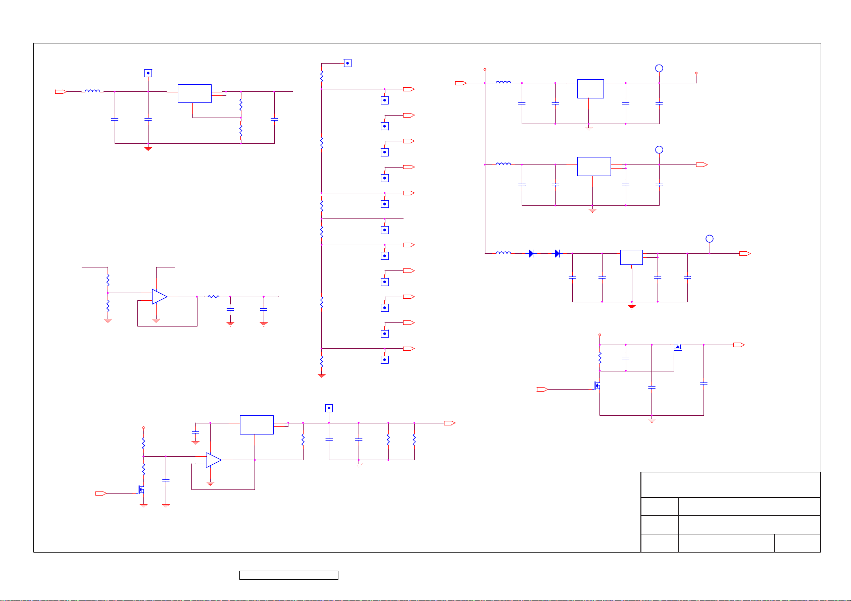
VAA
13.0V
VPREF1
VPREF1
VPREF
VOP1
VOP1
U7
U7
L15
L15
VAA
VPREF
R85
R85
R89
R89
1
VOP
3
Vin
C62
VSCN
C62
VOP
U10B
U10B
8
5
+
+
VSCN_OUT
7
6
-
-
4
C61
C61
2
Vout
4
Vout
ADJ
1
R87
R87
R66
R66
R69
R69
C72
C72
VPREF
C63
C63
VCN
C73
C73
1
R65
R65
GMA1
GMA1
1
GMA1
GMA1
GMA2
GMA2
1
GMA2
GMA2
R75
R75
R78
R78
R81
R81
R92
R92
R95
R95
1
1
1
1
1
1
1
1
1
GMA3
GMA3
GMA3
GMA4
GMA4
GMA4
GMA5
GMA5
GMA5
VCN
VCN1
VCN1
GMA6
GMA6
GMA6
GMA7
GMA7
GMA7
GMA8
GMA8
GMA8
GMA9
GMA9
GMA9
GMA10
GMA10
GMA10
GMA3
GMA4
GMA5
GMA6
GMA7
GMA8
GMA9
GMA10
V5A
V5A
L14
L14
V5A
C57
C57
L16
L16
C64
C64
L17
L17
D13
D13
2
1
U6
U6
3
C58
C58
3
C65
C65
D14
D14
2
1
C68
C68
1
Vin
Vout
GND
2
U8
U8
VI(5V)
VO(3.3V)
VO(3.3V)
GND
1
V33A
2
4
U9
U9
3
IN
C69
C69
R94
R94
V33A1
V33A1
TP
1
C59
C59
V33C1
V33C1
TP
1
C66
C66
4
OUT
2
OUT
GND
1
C70
C70
C74
C74
V33A
C60
C60
V33C
C67
C67
Q9
Q9
2
1
V33A
(PANEL VCC)
V33C
(SCALER VCC)
V25V1
V25V1
TP
1
(SCALER Core VCC)
C71
C71
3
V25V
(Panel VCC)
V33B
V25V
V33B
VCM1
U11
U11
VSCM
VOP
C79
C79
3
2
VCM_PWM
VCM_PWM
V5A
R101
R101
R102
R102
C82
C82
3
Q10
Q10
1
2
ViewSonic Corporation Confidential - Do Not Copy VA912-2
3
Vin
U10A
U10A
8
+
+
1
-
-
4
80
1
ADJ
Vout
Vout
VSCM_ADJ
2
4
VCM1
1
C80
C80
R98
R98
C81
C81
3
QP19
PANEL_ON/OFF
VCM
VCM
R99
R99
R100
R100
PANEL_ON/OFF
QP19
1
2
C77
C77
C76
C76
ViewSonic Corporation
Model
Title
Date Rev:
POWER
Page 84
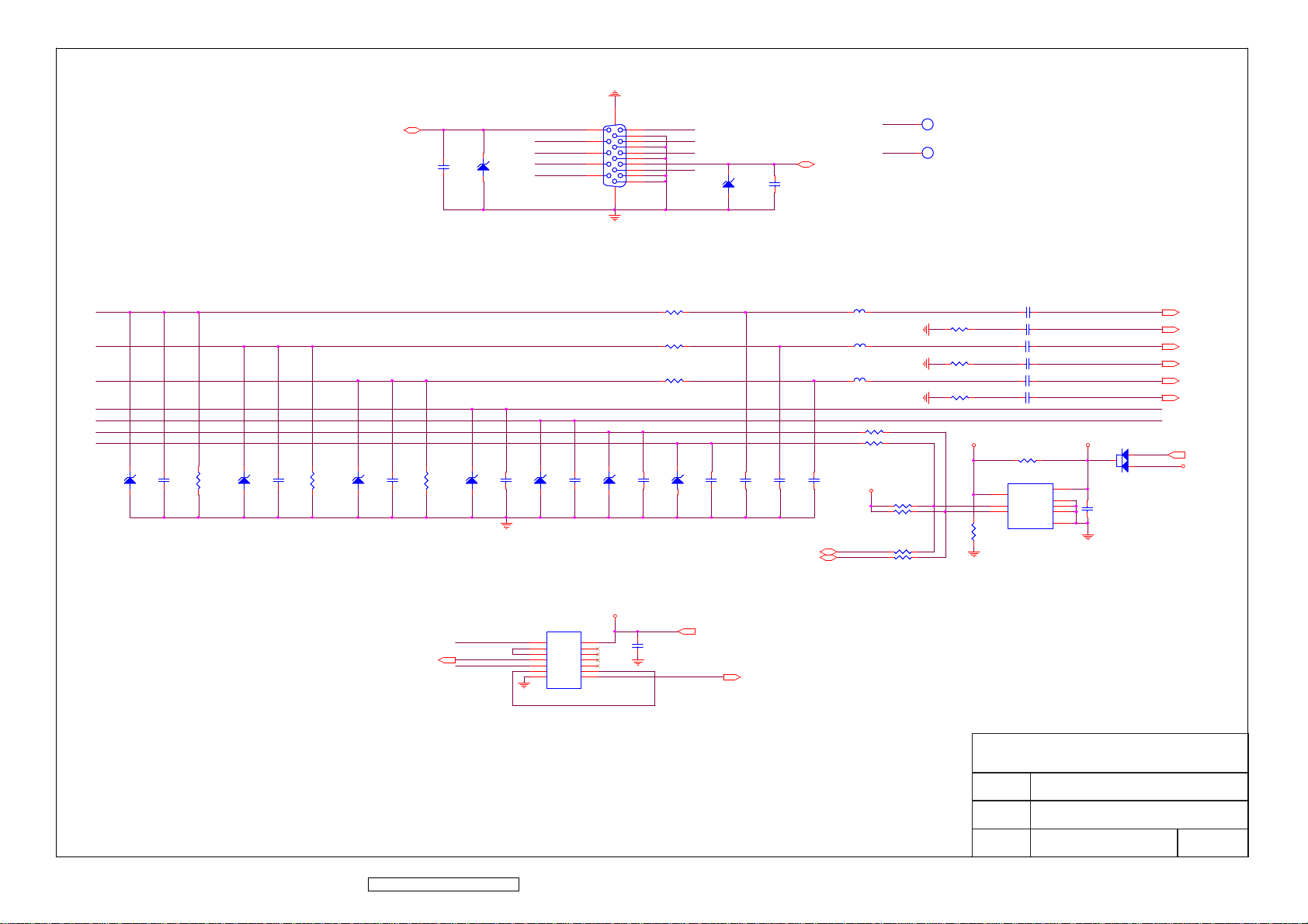
JP1JP1
TXD
2
C23C23
ZD3ZD3
1
TXD
GSDAI
G_HSYNC
G_VSYNC
GSCLI
16
1
11
6
2
12
7
3
13
8
4
14
9
5
15
10
17
GRAI
GGAI
GBAI
RXD
VGA_5V
2
ZD4ZD4
1
RXD
C24C24
TXD1TXD1
TXD
1
TP
RXD1RXD1
RXD
1
TP
GRAI
GGAI
GBAI
G_HSYNC
G_VSYNC
GSDAI
GSCLI
R40R40 L5L5
R42R42
R44R44
2
ZD5ZD5
1
2
ZD6ZD6
1
2
C33C33 C35C35
ZD7ZD7
R50R50 C40C40R49R49 R51R51
1
HSYNC
2
1
G_HSYNC
HSYNC
G_VSYNC
ZD8ZD8
2
ZD9ZD9
C34C34 C37C37C31C31
1
U4U4
1
1A
2
1Y
3
2A
4
2Y
5
3A
6
3Y
7
GND
2
ZD10ZD10
1
V33C
14
Vcc
13
6A
12
6Y
11
5A
10
5Y
09
4A
08
4Y
2
ZD11ZD11C36C36
1
V33C
C42C42
V33C
VSYNC
VSYNC
C38C38
C39C39
DDC_SCL
DDC_SDA
L6L6
L7L7
R46R46
R47R47
VGA_EDID_5V
DDC_SCL
DDC_SDA
R52R52
R53R53
R55R55
R56R56
R41R41
R43R43
R45R45
VGA_5V
C25C25
C26C26
C27C27
C28C28
C29C29
C30C30
R48R48
VGA_EDID_5V
U3U3
8
VCC
7
VCLK
6
SCL
5
SDA
R54R54
1
NC1
2
NC2
3
NC3
4
GND
VGA_EDID_5V
C41C41
RED+
RED-
GREEN+
GREEN-
BLUE+
BLUEG_HSYNC
G_VSYNC
3
D12D12C32C32
RED+
RED-
GREEN+
GREEN-
BLUE+
BLUE-
V5A
2
1
VGA_5V
V5A
VGA_5V
[Schmitt Trigger]
ViewSonic Corporation Confidential - Do Not Copy VA912-2
81
ViewSonic Corporation
Model
Title
Date Rev:
D_Sub INPUT
Page 85
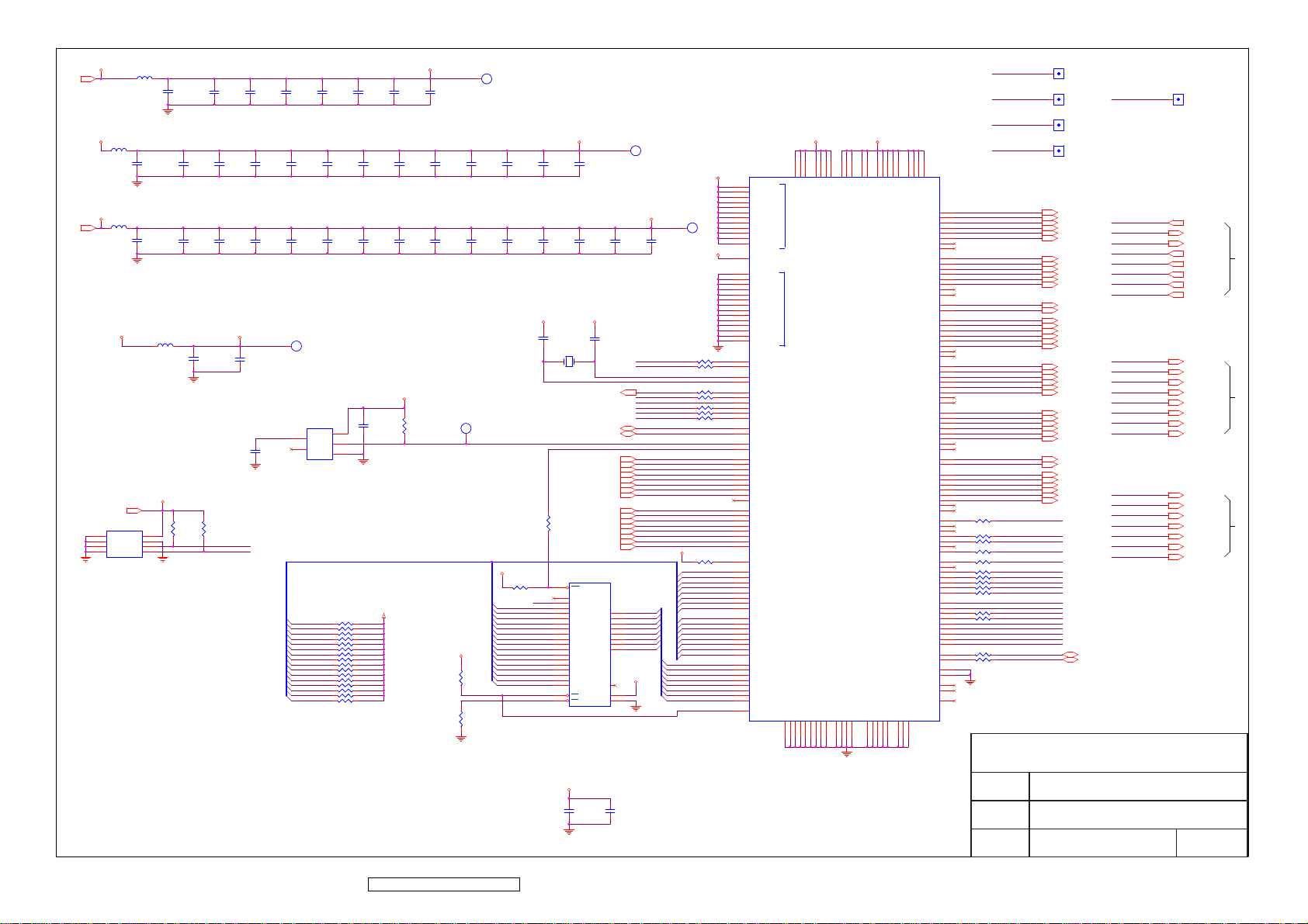
OSTH
STB
POL
ESTH
STV
CKV
OE
GVOFF
GVON
PWR_SW
NVRAM_SDA
NVRAM_SCL
KEY_UP
INV_ADJ
VOL_ADJ
VCM_PWM
AUDIO_ON
LED_GIRMADDR3
LED_OI
RXD
TXD
AUDIO_ON1AUDIO_ON1
1
PANEL_ON/OFF1PANEL_ON/OFF1
1
INV_ON/OFF1INV_ON/OFF1
1
VCM_PWM1VCM_PWM1
1
OR2P
OR2N
OR1P
OR1N
OR0P
OR0N
OG2P
OG2N
OG1P
OG1N
OG0P
OG0N
OCLKP
OCLKN
OB2P
OB2N
OB1P
OB1N
OB0P
OB0N
ER2P
ER2N
ER1P
ER1N
ER0P
ER0N
EG2P
EG2N
EG1P
EG1N
EG0P
EG0N
ECLKP
ECLKN
EB2P
EB2N
EB1P
EB1N
EB0P
EB0N
RXD
TXD
INV_ADJ1INV_ADJ1
1
PWR_SW
LED_GI
LED_OI
KEY_UP
KEY_DOWN
MENU
AUTO_ADJ
SOURCE_SELECT
PWR_SW
LED_GI
LED_OI
KEY_UP
KEY_DOWN
MENU
AUTO_ADJ
SOURCE_SELECT
[OSD I/O]
AUDIO_ON
PANEL_ON/OFF
INV_ON/OFF
VCM_PWM
VOL_ADJ
INV_ADJ
GVON
GVOFF
AUDIO_ON
PANEL_ON/OFF
INV_ON/OFF
VCM_PWM
VOL_ADJ
INV_ADJ
GVON
GVOFF
[CONTROL I/O]
OSTH
STB
POL
ESTH
STV
CKV
OE
OSTH
STB
POL
ESTH
STV
CKV
OE
[T-CON OUPUT]
C97C97
C110C110
C123C123
3_3V_DVDD
3_3V_DVDD
C89C89
C98C98
C111C111
3_3V_DVDD
R110R110
A0
A1
A2
A3
A4
A5
SCLPOL
H-PROTO
H-PORT-EN
OCM-START
A10
A11
A12
OSC-SEL
A14
A15
C90C90
3_3V_DVDD
C99C99
C112C112
V5A
/RESET1/RESET1
1
R141R141
R147R147
3_3V_DVDD13_3V_DVDD1
1
C100C100
C113C113
TP
TP
3_3V_DVDD 2_5V_VDD
171
162
101
198
178
167
RVDD76RVDD
RVDD
VDD_DPLL
VDD_SDDS
VDD_DDDS
3.3V_A
3.3V_A
AGND
AGND
RVSS77RVSS
RVSS
RVSS
EAVSS_RS14EAVSS_RS26AVSS_RS38OAVSS_RS48OAVSS_RS60CVSS85CVSS
102
179
199
RVDD
115
CVSS
36
158
121
127
VDD_RX2_2.5
VDD_RX1_2.5
VDD_RX0_2.5
CVSS
111
186
160
25
VDD1_ADC_2.5
VDD2_ADC_2.5
EAVDD_RS_2.513EAVDD_RS_2.5
GND1_ADC
GND2_ADC
GND_RX2
GND_RX1
157
159
116
122
110
47
59
37
AVDD_RS
CVDD_2.535CVDD_2.584CVDD_2.5
OAVDD_RS_2.5
OAVDD_RS_2.5
OCH11P_RS
OCH11N_RS
OCH10P_RS
OCH10N_RS
OCH9P_RS
OCH9N_RS
OCH8P_RS
OCH8N_RS
OCH7P_RS
OCH7N_RS
OCH6P_RS
OCH6N_RS
OCH5P_RS
OCH5N_RS
OCH4P_RS
OCH4N_RS
OCLKP_RS
OCLKN_RS
OCH3P_RS
OCH3N_RS
OCH2P_RS
OCH2N_RS
OCH1P_RS
OCH1N_RS
OCH0P_RS
OCH0N_RS
ECH11P_RS
ECH11N_RS
ECH10P_RS
ECH10N_RS
ECH9P_RS
ECH9N_RS
ECH8P_RS
ECH8N_RS
ECH7P_RS
ECH7N_RS
ECH6P_RS
ECH6N_RS
ECH5P_RS
ECH5N_RS
ECH4P_RS
ECH4N_RS
ECLKP_RS
ECLKN_RS
ECH3P_RS
ECH3N_RS
ECH2P_RS
ECH2N_RS
ECH1P_RS
ECH1N_RS
ECH0P_RS
ECH0N_RS
TCON_OSP
TCON_OPOL
TCON_OINV
DHS/TCON_LP
TCON_EPOL
TCON_EINV
TCON_ESP
TCON_RSP2
TCON_RSP3
TCON_RCLK
TCON_ROE
GPIO10/TCON_ROE3
GPIO9/TCON_ROE2
GPIO21/TCON_FSYNC
GPIO12/NVRAM_SDA
GPIO13/NVRAM_SCL
GPIO8/IRQINn
GPIO0/PWM0
GPIO1/PWM1
GPIO2/PWM2
GPIO3/TIMER1
GPIO6/TCON_SHC
GPIO7/TCON_TDIV
GPIO4/UART_DI
GPIO5/UART_DO
Reserved
Reserved
CLKOUT
GND_RX0
VSS_DPLL
VSS_DDDS
VSS_SDDS
128
170
166
161
185
CVDD_2.5
N/C
N/C
68
67
66
65
64
63
62
61
58
57
56
55
54
53
52
51
50
49
46
45
44
43
42
41
40
39
34
33
32
31
30
29
28
27
24
23
22
21
20
19
18
17
16
15
12
11
10
9
8
7
6
5
69
71
70
4
3
2
1
72
73
74
75
80
105
106
82
83
94
95
96
97
98
103
104
99
100
86
87
139
165
140
V5A
RMADDR15
RMADDR14
RMADDR13
RMADDR12
RMADDR11
RMADDR10
RMADDR9
RMADDR8
RMADDR7
RMADDR6
RMADDR5
RMADDR4
RMADDR3
RMADDR2
RMADDR1
RMADDR0
C101C101
C114C114
R123R123
3_3V_AVDD
3_3V_AVDD
C102C102
C103C103
C115C115
3_3V_AVDD 3_3V_AVDD
C119C119
X1X1
R111R111
U15U15
31
WE
30
NC/A17
A16
2
A16
3
A15
29
A14
28
A13
4
A12
25
A11
23
A10
26
A9
27
A8
5
A7
6
A6
7
A5
8
A4
9
A3
10
A2
11
A1
12
A0
24
OE
22
CE
32-Pin PLCC Socket
C120C120
DDC_SCL
DDC_SDA
GREEN+
GREEN-
BLUE+
BLUEHSYNC
VSYNC
DQ7
DQ6
DQ5
DQ4
DQ3
DQ2
DQ1
DQ0
NC
VCC
GND
3_3V_AVDD13_3V_AVDD1
1
TP
U12
2_5V_PLL
U12
164
AVDD_SDDS
169
AVDD_DDDS
173
AVDD_RPLL
112
AVDD_IMB
120
AVDD_RX2
126
AVDD_RX1
132
AVDD_RX0
135
AVDD_RXC
141
AVDD_BLUE
145
AVDD_GREEN
149
AVDD_RED
153
AVDD_ADC
138
VDD_RXPLL_2.5
114
AGND_IMB
117
AGND_RX2
123
AGND_RX1
129
AGND_RX0
136
AGND_RXC
137
GND_RXPLL
156
SGND_ADC
155
AGND_ADC
144
AGND_BLUE
148
AGND_GREEN
152
AGND_RED
172
AVSS_RPLL
168
AVSS_DDDS
163
AVSS_SDDS
78
PPWR
79
PBIAS
175
TCLK
174
XTAL
90
GPIO20/HDATA3
91
GPIO19/HDATA2
92
GPIO18/HDATA1
93
GPIO17/HDATA0
89
GPIO16/HFS
88
GPIO22/HCLK
108
GPIO14/DDC_SCL
109
GPIO15/DDC_SDA
107
RESETn
81
GPIO11/ROM_WEn
150
RED+
151
RED-
146
GREEN+
147
GREEN-
142
BLUE+
143
BLUE-
176
HSYNC
177
VSYNC
154
ADC_TEST
133
RXC+
134
RXC-
118
RX2+
119
RX2-
124
RX1+
125
RX1-
130
RX0+
131
RX0-
113
REXT
180
ROM_ADDR15
181
ROM_ADDR14
182
ROM_ADDR13
183
ROM_ADDR12
184
ROM_ADDR11
187
ROM_ADDR10
188
ROM_ADDR9
189
ROM_ADDR8
190
ROM_ADDR7
191
ROM_ADDR6
192
ROM_ADDR5
193
ROM_ADDR4
194
ROM_ADDR3
195
ROM_ADDR2
196
ROM_ADDR1
197
ROM_ADDR0
200
ROM_DATA7
201
ROM_DATA6
202
ROM_DATA5
203
ROM_DATA4
204
ROM_DATA3
205
ROM_DATA2
206
ROM_DATA1
207
ROM_DATA0
208
ROM_OEn
3_3V_AVDD
2_5V_VDD
2_5V_VDD12_5V_VDD1
2_5V_VDD
1
C118C118
RMDATA[0..7]
R103R103
R104R104
R105R105
R106R106
R107R107
R108R108
R109R109
3_3V_AVDD
R118R118
TP
RMADDR15
RMADDR14
RMADDR13
RMADDR12
RMADDR11
RMADDR10
RMADDR9
RMADDR8
RMADDR7
RMADDR6
RMADDR5
RMADDR4
RMADDR3
RMADDR2
RMADDR1
RMADDR0
RMDATA7
RMDATA6
RMDATA5
RMDATA4
RMDATA3
RMDATA2
RMDATA1
RMDATA0
FLASH_OEn
C117C117C107C107 C116C116
PANEL_ON/OFF
INV_ON/OFF
TCLK
XTAL
XAO
KEY_DOWN
A16
SOURCE_SELECT
AUTO_ADJ
MENU
/RESET
RED+
RED-
RXC+
RXCRX2+
RX2-
RX1+
RX1RX0+
RX0-
RMDATA7
21
RMDATA6
20
RMDATA5
19
RMDATA4
18
RMDATA3
17
RMDATA2
15
RMDATA1
14
RMDATA0
13
V5A
1
32
16
AUDIO_ON
PANEL_ON/OFF INV_ADJ
INV_ON/OFF
VCM_PWM
OR2P
OR2N
OR1P
OR1N
OR0P
OR0N
OG2P
OG2N
OG1P
OG1N
OG0P
OG0N
OCLKP
OCLKN
OB2P
OB2N
OB1P
OB1N
OB0P
OB0N
ER2P
ER2N
ER1P
ER1N
ER0P
ER0N
EG2P
EG2N
EG1P
EG1N
EG0P
EG0N
ECLKP
ECLKN
EB2P
EB2N
EB1P
EB1N
EB0P
EB0N
R112R112
R115R115
R116R116
R117R117
R119R119
R120R120
R121R121
R122R122
R124R124
R125R125
R126R126
R127R127
R135R135
R137R137
V33C
L18L18
V33C
V33C
V33C
L19L19
V25V
L20L20
V25V
V25V
V5A
NVRAM
U14U14
1
A0
2
A1
3
A2
VSS4SI
C83C83
C84C84
C91C91
C104C104
L21L21
V25V
V5A
V5A
8
VCC
7
WP
6
SCK
5
C93C93
C92C92
C105C105
C106C106
2_5V_PLL
C121C121
R113R113
R114R114
NVRAM_SCL
NVRAM_SDA
C86C86
C85C85
C95C95
C94C94
C108C108
2_5V_PLL12_5V_PLL1
2_5V_PLL
1
C122C122
TP
U13U13
Reset
Circuit
5
4
RMADDR0
RMADDR1
RMADDR2
RMADDR4
RMADDR5
RMADDR6
RMADDR7
RMADDR8
RMADDR9
RMADDR10
RMADDR11
RMADDR12
RMADDR13
RMADDR14
RMADDR15
CD
NC
RMADDR[0..15]
C124C124
Default Jumper settings are shown above
C96C96
C109C109
2
VCC
1
RSTN
3
GND
R128R128
R129R129
R130R130
R131R131
R132R132
R133R133
R134R134
R136R136
R138R138
R139R139
R140R140
R142R142
R143R143
R144R144
R145R145
R146R146
Solid/White = 10K IN/OUT
C88C88C87C87
V5A
C125C125
ViewSonic Corporation Confidential - Do Not Copy VA912-2
82
ViewSonic Corporation
Model
C126C126
Title
Date Rev:
SCALER
Page 86
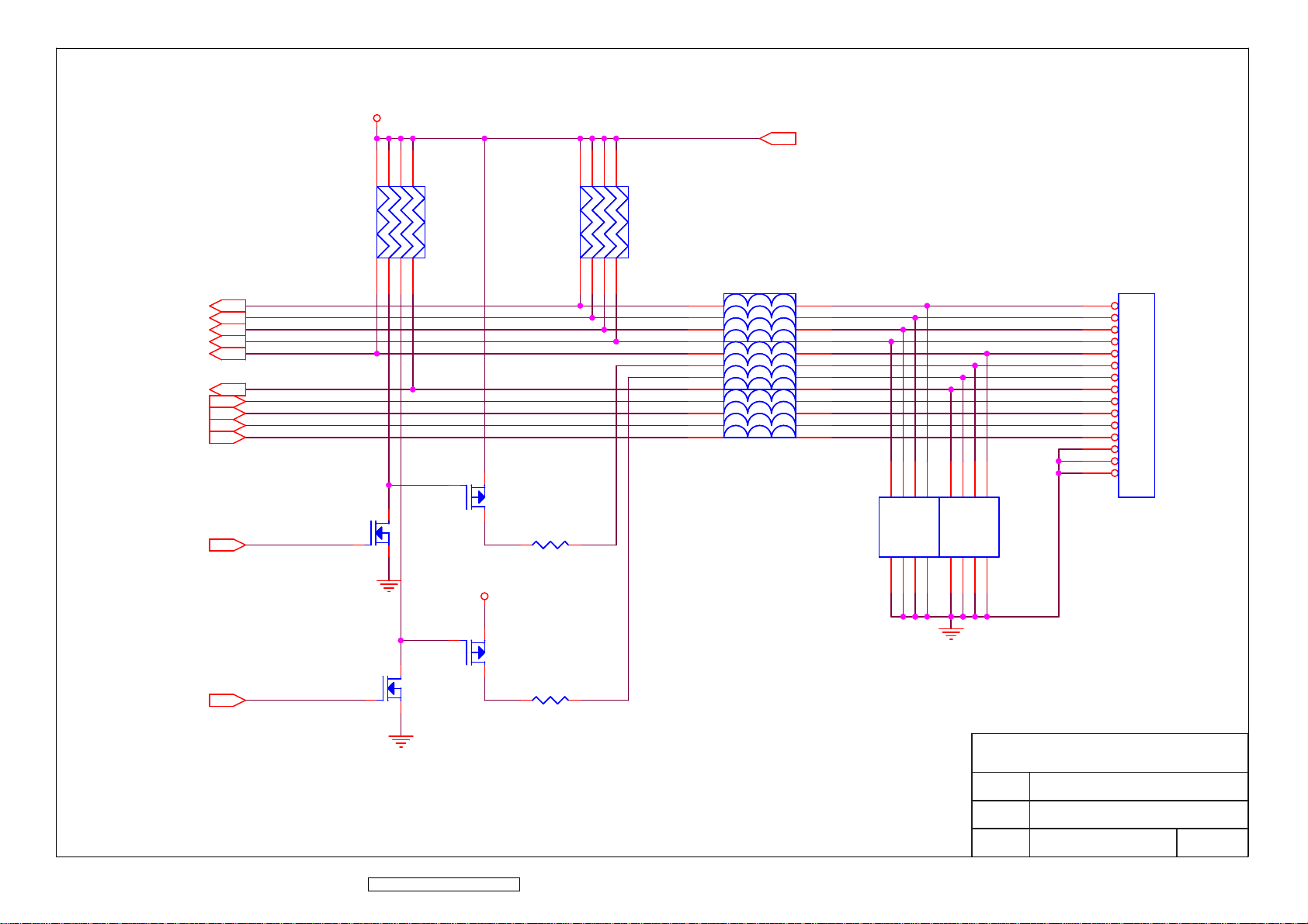
SOURCE_SELECT
AUTO_ADJ
MENU
KEY_DOWN
KEY_UP
PWR_SW
AUDIO/R+
AUDIO/RAUDIO/L+
AUDIO/L-
LED_GI
SOURCE_SELECT
AUTO_ADJ
MENU
KEY_DOWN
KEY_UP
PWR_SW
AUDIO/R+
AUDIO/RAUDIO/L+
AUDIO/L-
LED_GI
V5A
V5A
785
785
6
RP46RP46
312
4
V5A
Q3Q3
3 2
R57R57
1
32
Q4Q4
1
6
RP47RP47
312
4
LP84LLP8
LED_G
LED_O
4L
LP74LLP7
1
2
4L
3
4
1
2
4L
3
4
1
2
3
4
LP94LLP9
V5A
8
7
6
5
8
7
6
5
8
7
6
5
CP33CACP33
4
C3D
CA
D5C6B7A
CN2CN2
15
14
13
12
11
10
9
8
7
6
5
4
3
2
1
A1B
4
C3D
CA
D5C6B7A
2
A1B
CP34CACP34
8
2
8
1
32
LED_OI
ViewSonic Corporation Confidential - Do Not Copy VA912-2
LED_OI
1
83
Q6Q6
Q5Q5
3 2
R58R58
ViewSonic Corporation
Model
Title
Date Rev:
OSD Interface
Page 87
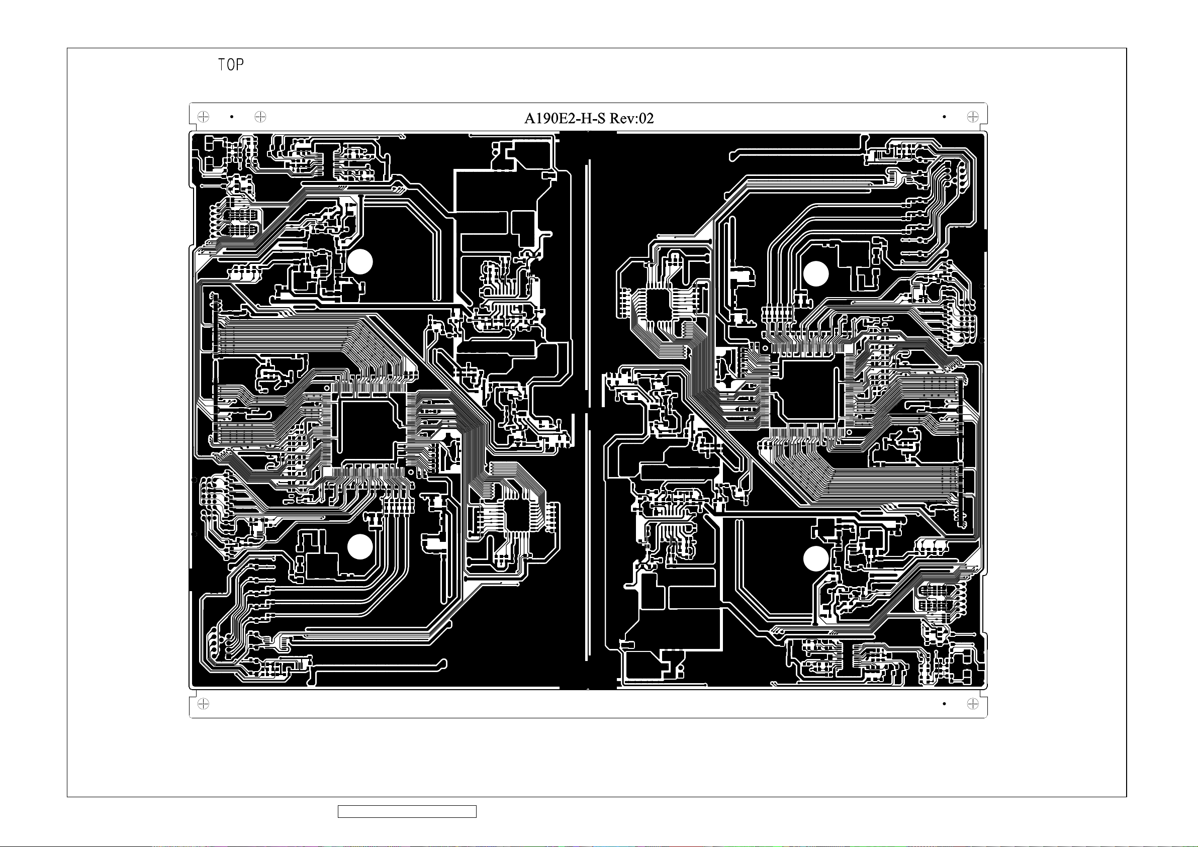
11. PCB Layout Diagrams
ViewSonic Corporation Confidential - Do Not Copy VA912-2
84
Page 88
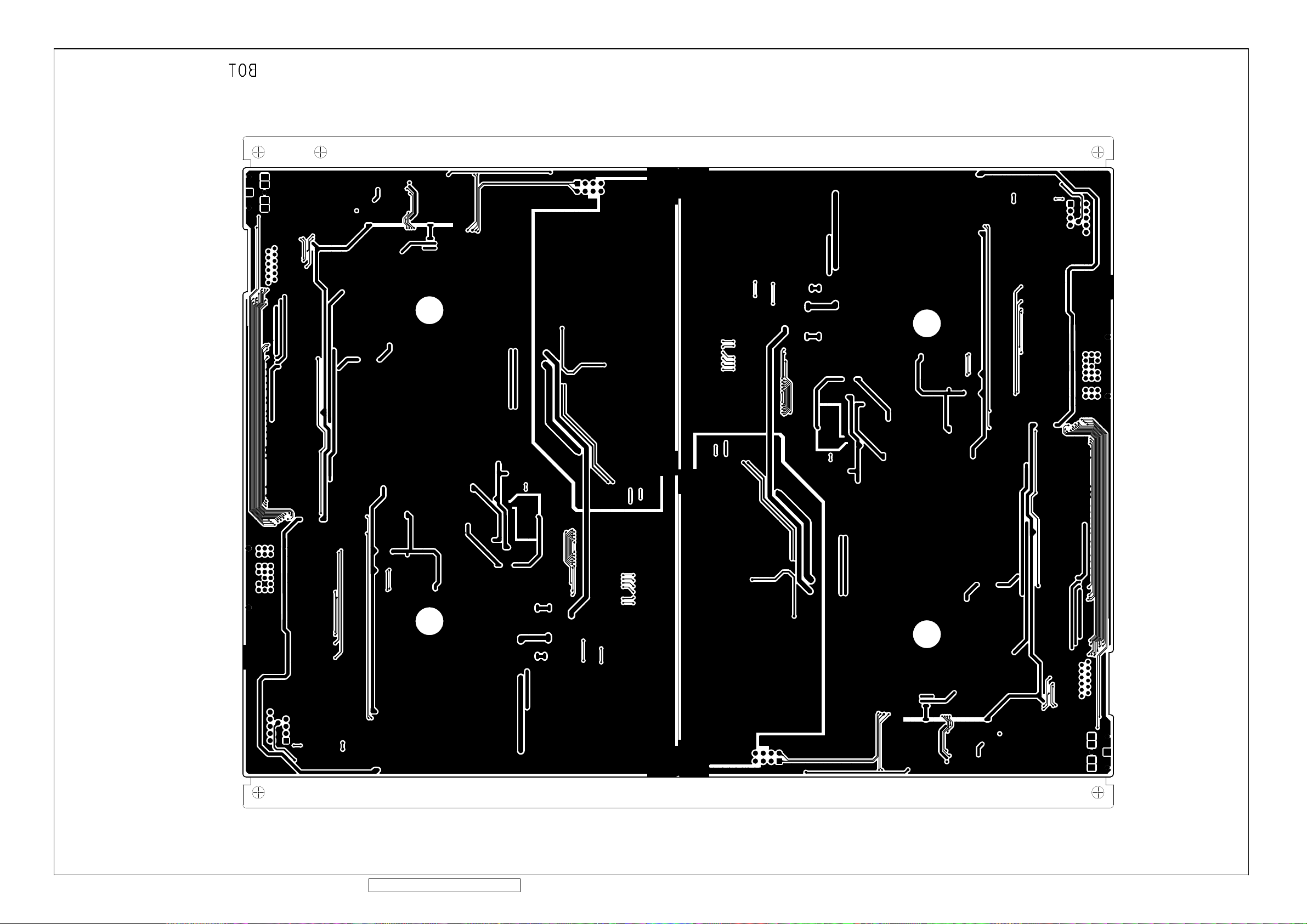
ViewSonic Corporation Confidential - Do Not Copy VA912-2
85
Page 89

ViewSonic Corporation Confidential - Do Not Copy VA912-2
86
Page 90
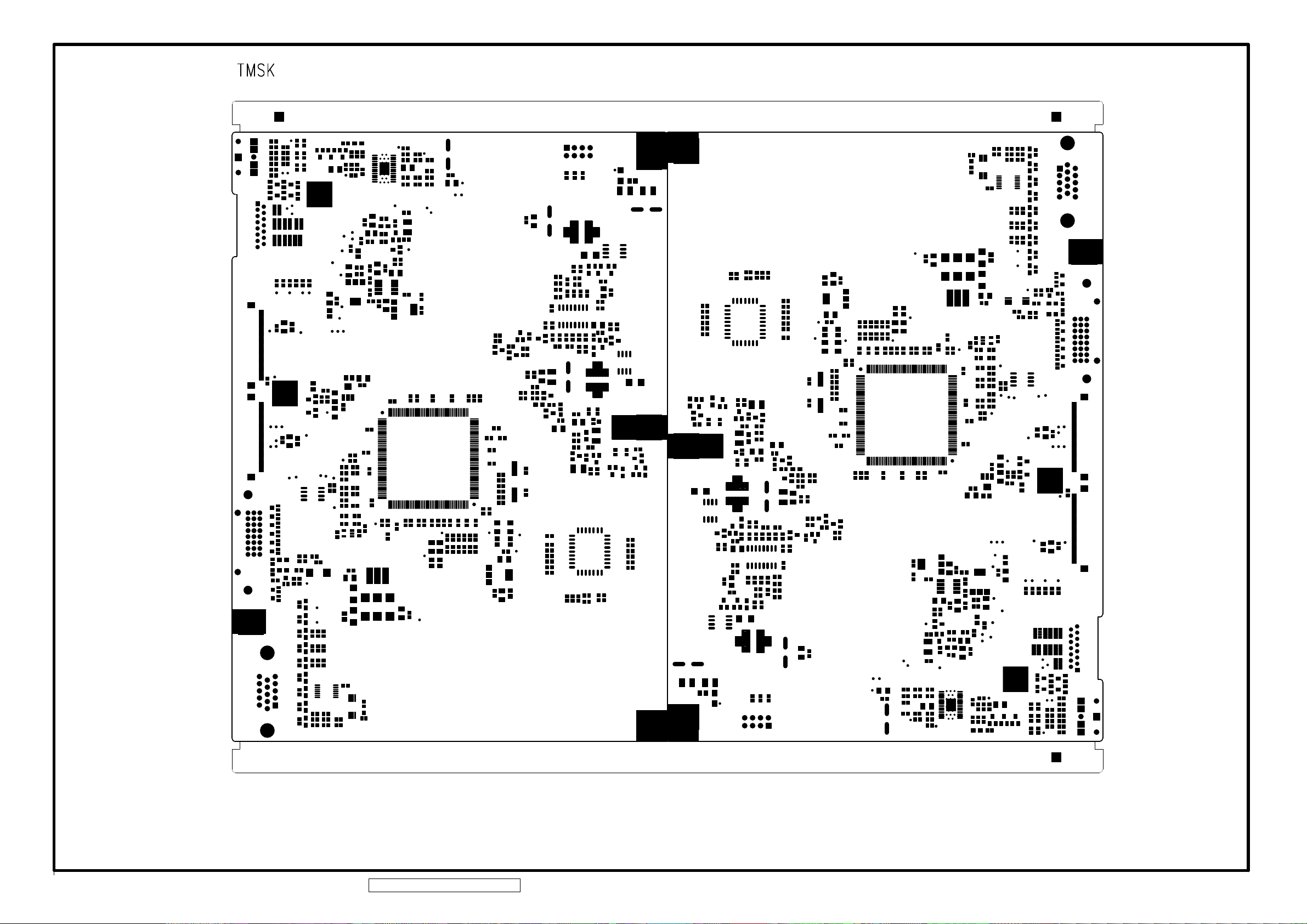
ViewSonic Corporation Confidential - Do Not Copy VA912-2
87
Page 91
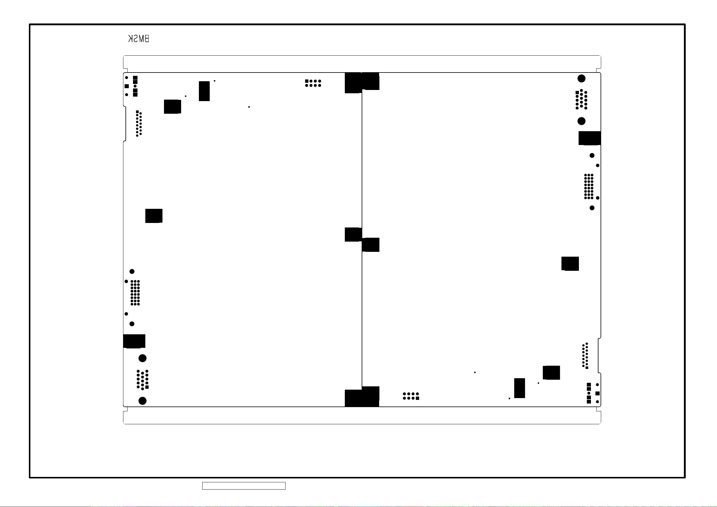
ViewSonic Corporation Confidential - Do Not Copy VA912-2
88
Page 92
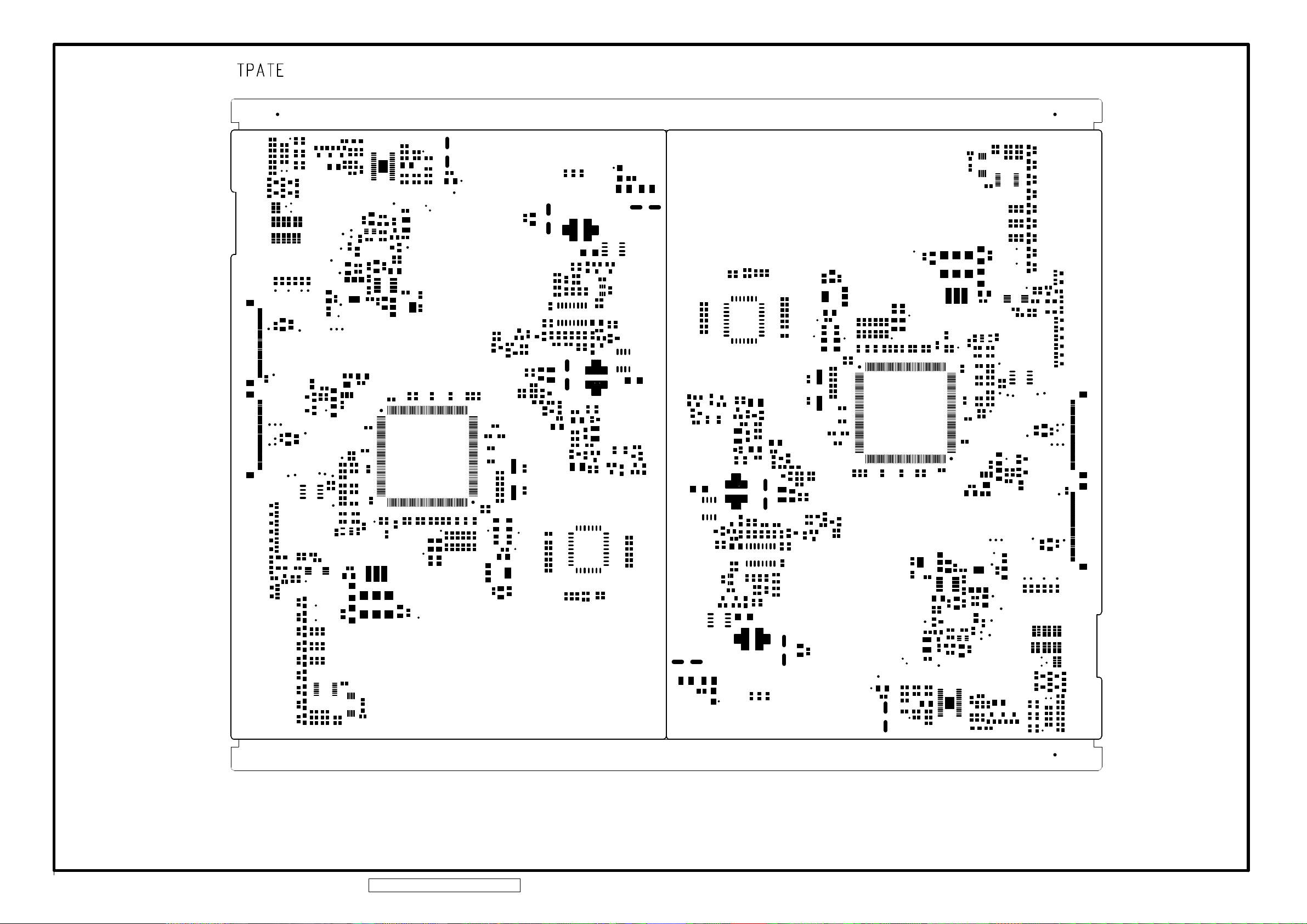
ViewSonic Corporation Confidential - Do Not Copy VA912-2
89
Page 93

ViewSonic Corporation Confidential - Do Not Copy VA912-2
90
Page 94

ViewSonic Corporation Confidential - Do Not Copy VA912-2
91
Page 95
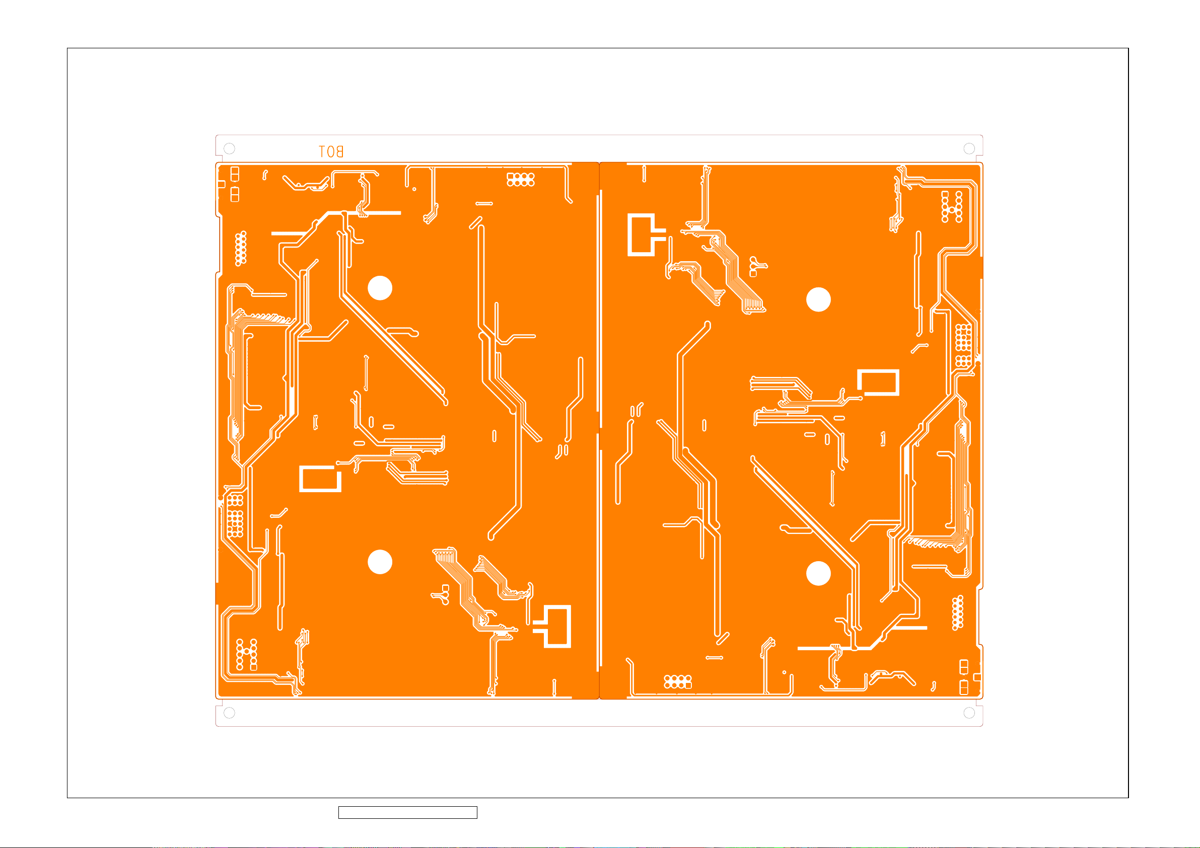
ViewSonic Corporation Confidential - Do Not Copy VA912-2
92
Page 96
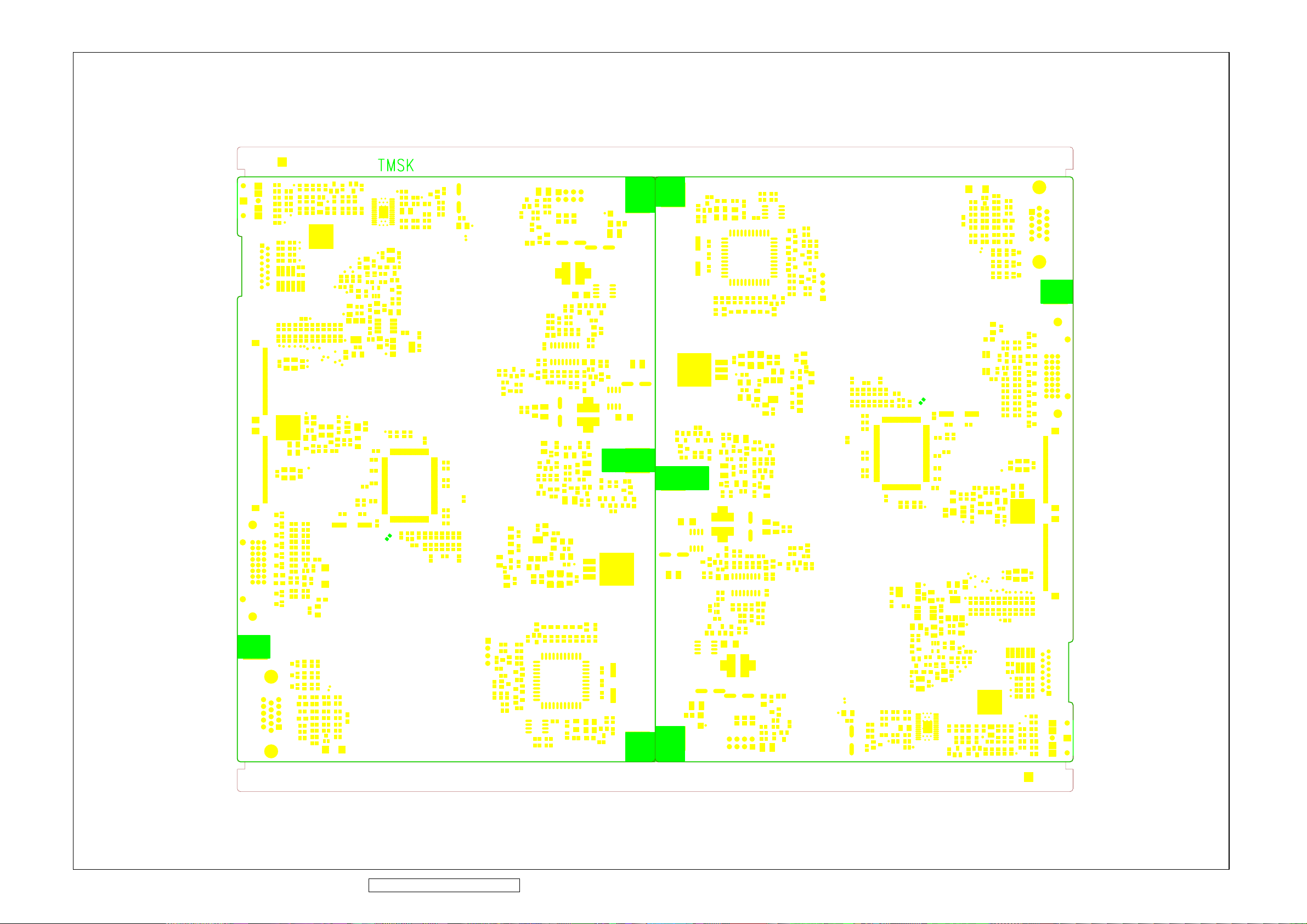
ViewSonic Corporation Confidential - Do Not Copy VA912-2
93
Page 97
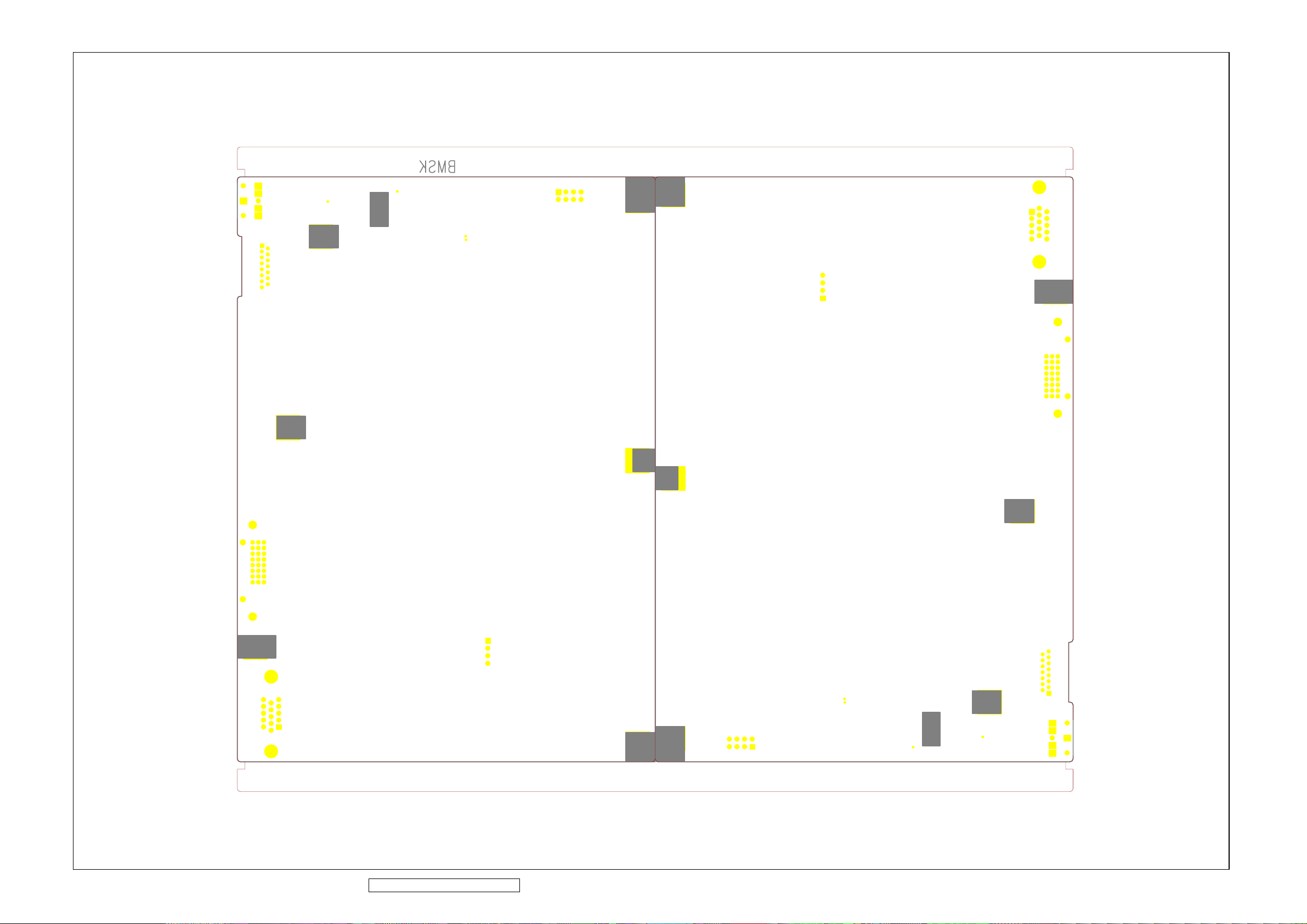
ViewSonic Corporation Confidential - Do Not Copy VA912-2
94
Page 98
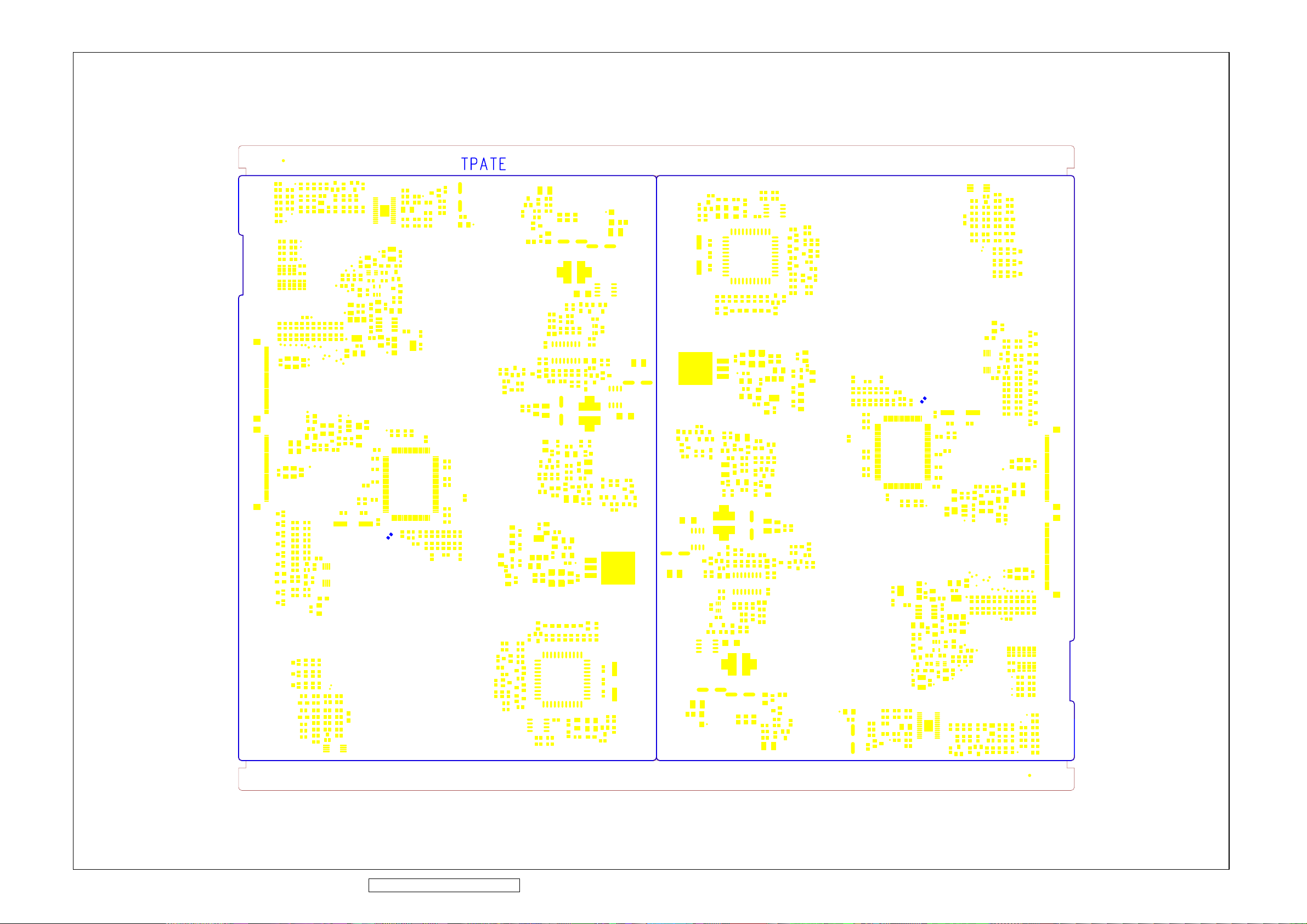
ViewSonic Corporation Confidential - Do Not Copy VA912-2
95
Page 99
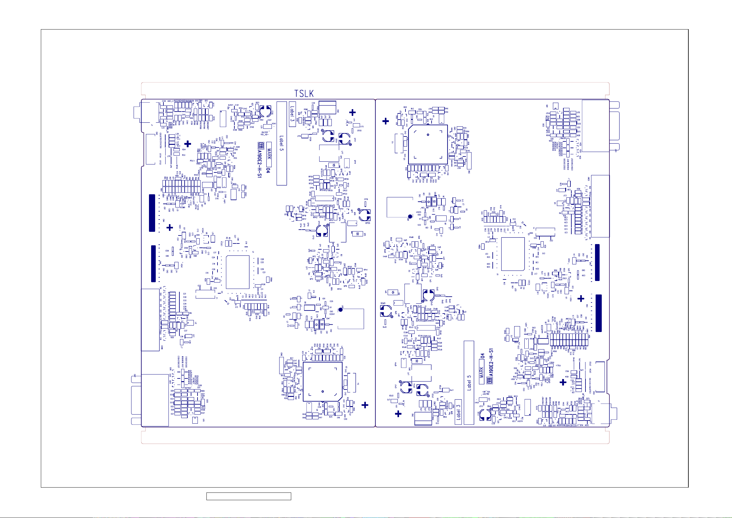
ViewSonic Corporation Confidential - Do Not Copy VA912-2
96
Page 100

ViewSonic Corporation Confidential - Do Not Copy VA912-2
97
 Loading...