

Page 1

ViewSonic VA712-2
VA712b-2
Model No. VS10901
17” Color TFT LCD Display
(VA712-2_ VA712b-2_SM Rev. 1a Apr. 2006)
ViewSonic 381 Brea Canyon Road, Walnut, California 91789 USA – (800) 888-8583
Service Manual
Page 2
ViewSonic Corporation Confidential - Do Not Copy VA712-2_ VA712b-2
i
Copyright
Copyright © 2006 by ViewSonic Corporation. All rights reserved. No part of this publication
may be reproduced, transmitted, transcribed, stored in a retrieval system, or translated into any
language or computer language, in any form or by any means, electronic, mechanical, magnetic,
optical, chemical, manual or otherwise, without the prior written permission of ViewSonic
Corporation.
Disclaimer
ViewSonic makes no representations or warranties, either expressed or implied, with respect to
the contents hereof and specifically disclaims any warranty of merchantability or fitness for any
particular purpose. Further, ViewSonic reserves the right to revise this publication and to make
changes from time to time in the contents hereof without obligation of ViewSonic to notify any
person of such revision or changes.
Trademarks
Opt quest is a registered trademark of ViewSonic Corporation.
ViewSonic is a registered trademark of ViewSonic Corporation.
All other trademarks used within this document are the property of their respective owners.
Revision History
Revision SM Editing Date ECR Number Description of Changes Editor
1a 4/12/2006 Initial Release Jamie Chang
Page 3
ViewSonic Corporation Confidential - Do Not Copy VA712-2_ VA712b-2
ii
TABLE OF CONTENTS
1. Precautions and Safety Notices 1
2. Specification 4
3. Front Panel Function Control Description 8
4. Circuit Description 14
5. Adjustment Procedure 26
6. Troubleshooting Flow Chart 49
7. Recommended Spare Parts List 50
8. Exploded Diagram and Exploded Parts List 56
9. Block Diagram 60
10. Schematic Diagrams 61
11. PCB Layout Diagrams 69
Page 4

ViewSonic Corporation Confidential - Do Not Copy VA712-2_ VA712b-2
1
1. Precautions and Safety Notices
1.1 SAFETY PRECAUTIONS
This monitor is manufactured and tested on a ground principle that a user’s safety comes first.
However, improper use or installation may cause damage to the monitor as well as the user.
Carefully go over the following WARNINGS before installing and keep this guide handy.
WARNINGS
.This monitor should be operated only at the correct power sources indicated on the label on
the rear end of the monitor. If you’re unsure of the power supply in your residence, consult
you local dealer or power company.
.Use only the special power adapter that comes with this monitor for power input.
.Do not try to repair the monitor your self as it contains no user-serviceable parts. This monitor
should only be repaired by a qualified technician.
.Do not remove the monitor cabinet. There is high-voltage parts inside that may cause electric
shock to human bodies, even when the power cord is unplugged.
.Stop using the monitor if the cabinet is damaged. Have it checked by a service technician.
.Put your monitor only in a clean, dry environment. If it gets wet, unplug the power cable
immediately and consult your service technician.
.Always unplug the monitor before cleaning it .Clean the cabinet with a clean, dry cloth. Apply
non-ammonia based cleaner onto the cloth, not directly onto the glass screen.
.Keep the monitor away from magnetic objects, motors, TV sets, and transformer.
.Do not place heavy objects on the monitor or power cord.
1.2 PRODUCT SAFETY NOTICE
Many electrical and mechanical parts in this chassis have special safety visual inspections and
the protection afforded by them cannot necessarily be obtained by using replacement
components rated for higher voltages, wattage, etc. Before replacing any of these components
read the parts list in this manual carefully. The use of substitute replacement parts which do
not have the same safety characteristics as specified in the parts list may create shock, fire ,or
other hazards.
1.3 SERVICE NOTES
1. When replacing parts or circuit boards, clamp the lead wires around terminals before
soldering.
2. When replacing a high wattage resistor(more than 1W of metal oxide film resistor) in circuit
board, keep the resistor about 5mm away from circuit board.
3. Keep wires away from high voltage, high temperature components and sharp edges.
4. Keep wires in their original position so as to reduce interference.
5. Usage of this product please refers to also user’s manual.
Page 5
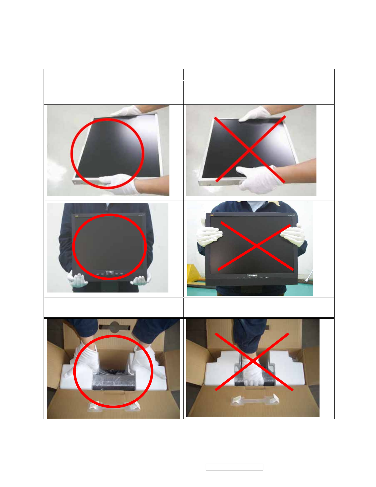
1.4 HANDING AND PLACING METHODS
Correct Methods: Incorrect Methods:
Only touch the metal frame of the LCD
panel or the front cover of the monitor. Do
not touch the surface of the polarizer.
Surface of the LCD panel is pressed by fingers
and that may cause “Mura.”
Take out the monitor with cushions
Taking out the monitor by grasping the LCD
panel. That may cause “Mura.”
ViewSonic Corporation Confidential - Do Not Copy VA712-2_ VA712b-2
2
Page 6
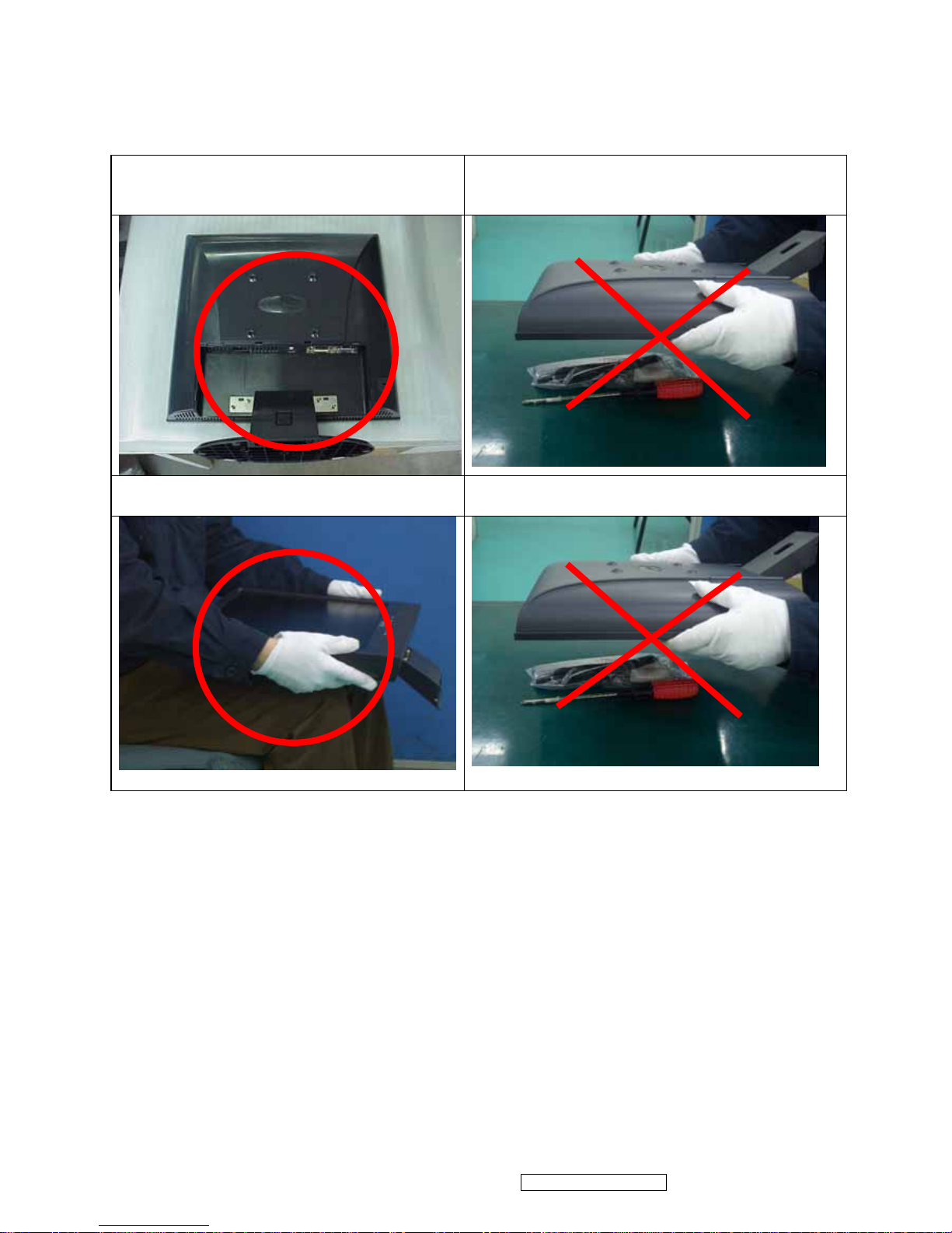
Place the monitor on a clean and soft foam
pad.
Placing the monitor on foreign objects. That
could scratch the surface of the panel or cause
“Mura.”
Place the monitor on the lap, the panel
surface must be upwards.
The panel is placed facedown on the lap. That
may cause “Mura.”
ViewSonic Corporation Confidential - Do Not Copy VA712-2_ VA712b-2
3
Page 7
ViewSonic Corporation Confidential - Do Not Copy VA712-2_ VA712b-2
4
2. Specification
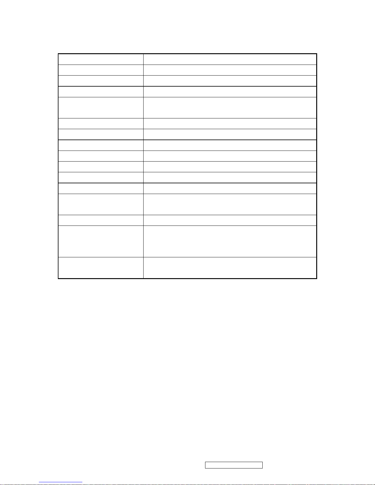
2.1 PRODUCT SPECIFICATIONS
LCD Panel 17.0” TFT
Recommend Resolution
1280 x1024@60Hz
Pixel Dimension 0.264(H) x 0.264(V)mm
LCD Display Color 16.2M Colors (RGB 6-bit+FRC data)
Viewing Angle
Horizontal: 140 °
Vertical: 130 °
Contrast Ratio
500:1 (Typ.)
Brightness
300 cd/㎡(Typ.)
Response Time 8ms(Typ.)
Active Display Area 337.9mm(H) x 270.3mm(V)
Maximum Pixel Clock 135 MHz
Horizontal Frequency
30 – 82 kHz
Vertical Refresh Rate
50 – 85 Hz.
Temperature
Operating: 0°C to +40°C
Storage: -20°C to +60°C
Input Signal Analog / Digital
Power Management
Energy Star compliant VESA
DPMS compatible
≦1 W
Power
Input Voltage : 90V~264ACV,50~60Hz(auto switch)
Consumption: 39 Watts(Max.) 36 Watts(Typ.)
Page 8
ViewSonic Corporation Confidential - Do Not Copy VA712-2_ VA712b-2
5
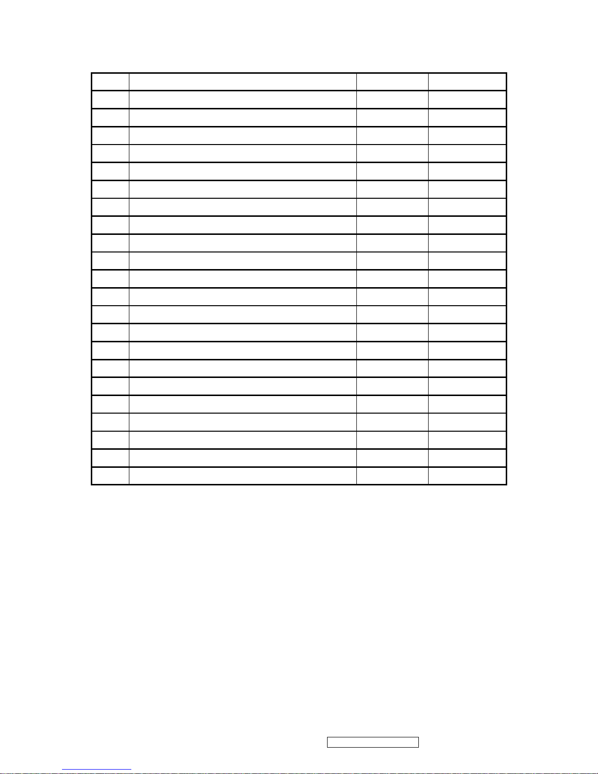
2.2 FACTORY SUPPORTING MODES
Timing Table :
Item Timing Analog Digital
1 640 x 350 @ 70Hz, 31.5kHz Yes Yes
2 640 x 480 @ 60Hz, 31.5kHz Yes Yes
3 640 x 480 @ 67Hz, 35.0kHz Yes Yes
4 640 x 480 @ 72Hz, 37.9kHz Yes Yes
5 640 x 480 @ 75Hz, 37.5kHz Yes Yes
6 640 x 480 @ 85Hz, 43.27kHz Yes Yes
7 720 x 400 @ 70Hz, 31.5kHz Yes Yes
8 800 x 600 @ 56Hz, 35.1kHz Yes Yes
9 800 x 600 @ 60Hz, 37.9kHz Yes Yes
10 800 x 600 @ 72Hz, 48.1kHz Yes Yes
11 800 x 600 @ 75Hz, 46.9kHz Yes Yes
12 800 x 600 @ 85Hz, 53.7kHz Yes Yes
13 832 x 624 @ 75Hz, 49.7kHz Yes Yes
14 1024 x 768 @ 60Hz, 48.4kHz Yes Yes
15 1024 x 768 @ 70Hz, 56.5kHz Yes Yes
16 1024 x 768 @ 72Hz, 58.1kHz Yes Yes
17 1024 x 768 @ 75Hz, 60.0kHz Yes Yes
18 1024 x 768 @ 85Hz, 68.67kHz Yes Yes
19 1152 x 870 @ 75Hz, 68.6kHz Yes Yes
20 1280 x 1024 @ 60Hz, 63.4kHz Yes Yes
21 1280 x 1024 @ 75Hz, 79.97kHz Yes Yes
22 1280 x 720 @ 60Hz, 45kHz Yes Yes
Primary Preset::VESA : 1280 x1024@60Hz
Page 9
ViewSonic Corporation Confidential - Do Not Copy VA712-2_ VA712b-2
6
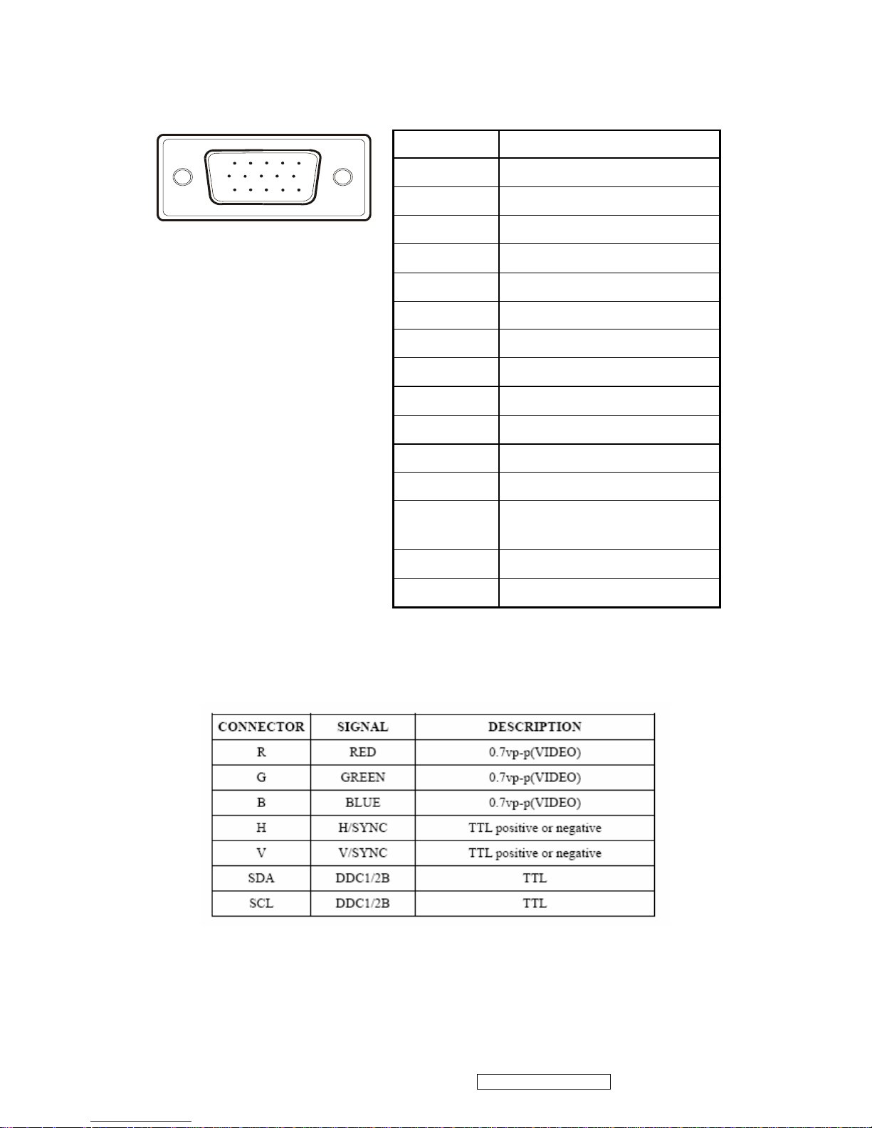
2.3 INTERFACE DESCRIPTION
D-SUB 15 PIN CONNECTOR
15
6
10
11 15
Pin Number Pin Function
1 Red video input
2 Green video input
3 Blue video input
4 No Connection
5 Ground
6 Red video ground
7 Green video ground
8 Blue video ground
9 +5V
10 H/V sync ground
11 No connection
12 (SDA)
13
Horizontal sync (Composite
sync)
14 Vertical sync
15 (SCL)
SIGNAL LEVEL
Page 10
ViewSonic Corporation Confidential - Do Not Copy VA712-2_ VA712b-2
7
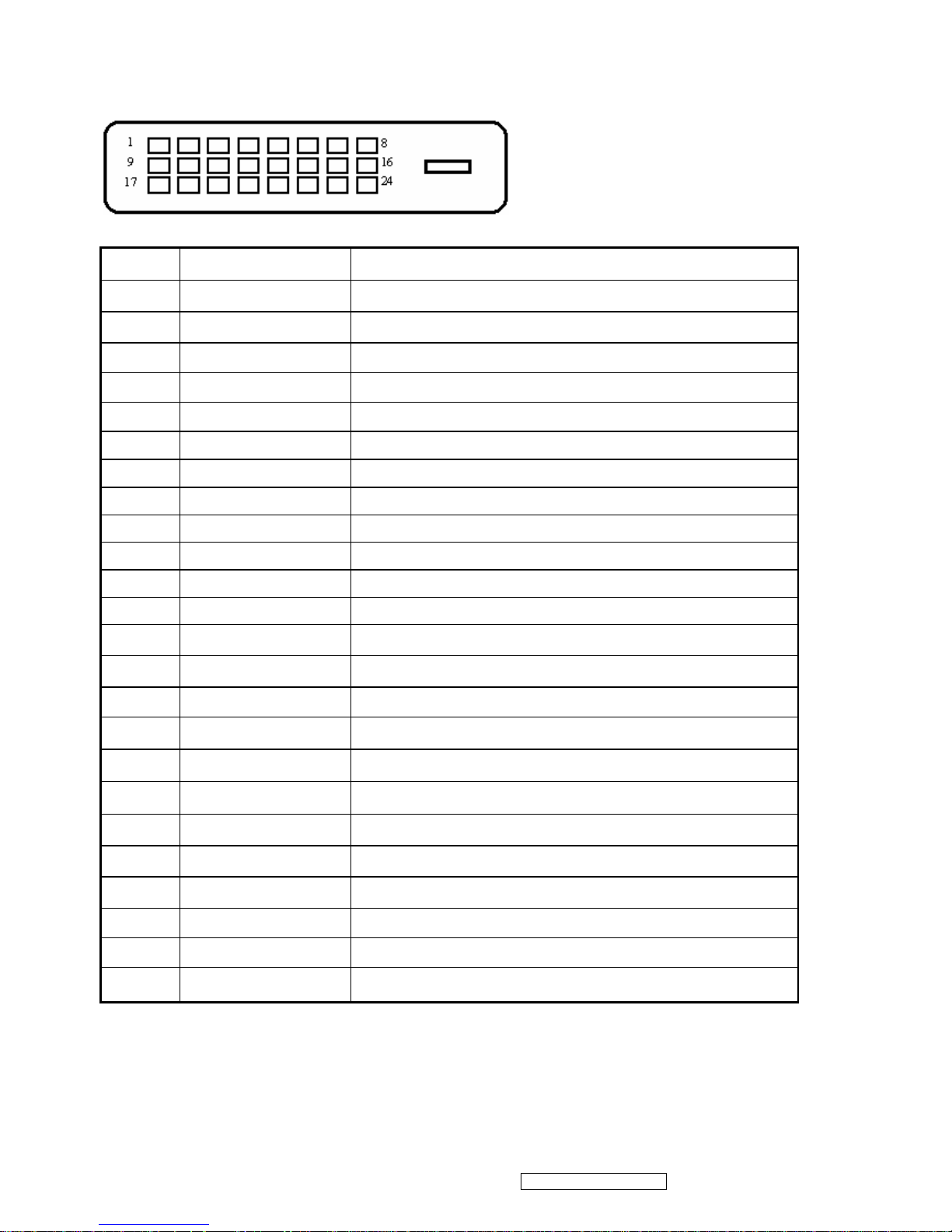
DVI-D 24 PIN CONNECTOR
Pin No. Signal Name Description
1 RX2- TMDS negative differential input, channel 2
2 RX2+ TMDS positive differential input, channel 2
3 GND Logic Ground
4 Reserved 4 Reserved. No connection
5 Reserved 5 Reserved. No connection
6 DDC-CLK DDC2B Clock
7 DDC-DAT DDC2B Data
8 Reserved 8 Reserved. No connection
9 RX1- TMDS negative differential input, channel 1
10 RX1+ TMDS positive differential input, channel 1
11 GND Logic Ground
12 Reserved 12 Reserved. No connection
13 Reserved 13 Reserved. No connection
14 VCCX Power
15 GND Logic Ground
16 SENS SENSE Pin, Pull High
17 RX0- TMDS negative differential input, channel 0
18 RX0+ TMDS positive differential input, channel 0
19 GND Logic Ground
20 Reserved 20 Reserved. No connection
21 Reserved 21 Reserved. No connection
22 GND Logic Ground
23 RXC+ TMDS positive differential input, reference clock
24 RXC- TMDS negative differential input, reference clock
Page 11
ViewSonic Corporation Confidential - Do Not Copy VA712-2_ VA712b-2
8
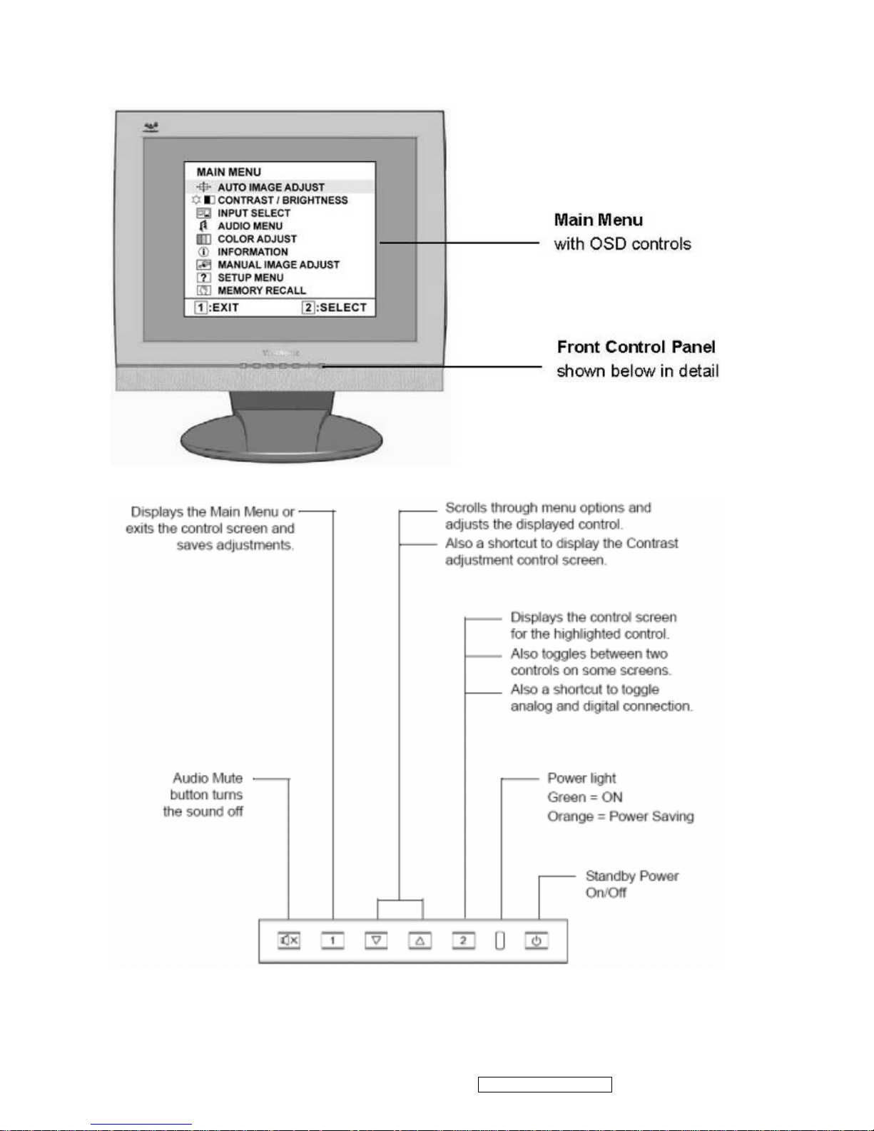
3. Front Panel Function Control Description
Page 12
ViewSonic Corporation Confidential - Do Not Copy VA712-2_ VA712b-2
9
Do the following to adjust the display setting:
1. To display the Main Menu, press button [1].
NOTE: All OSD menus and adjustment screens disappear automatically after about 15 seconds.
This is adjustable through the OSD timeout setting in the setup menu.
2. To select a control to adjust, press or ▼ to ▲ scroll up or down in the Main Menu.
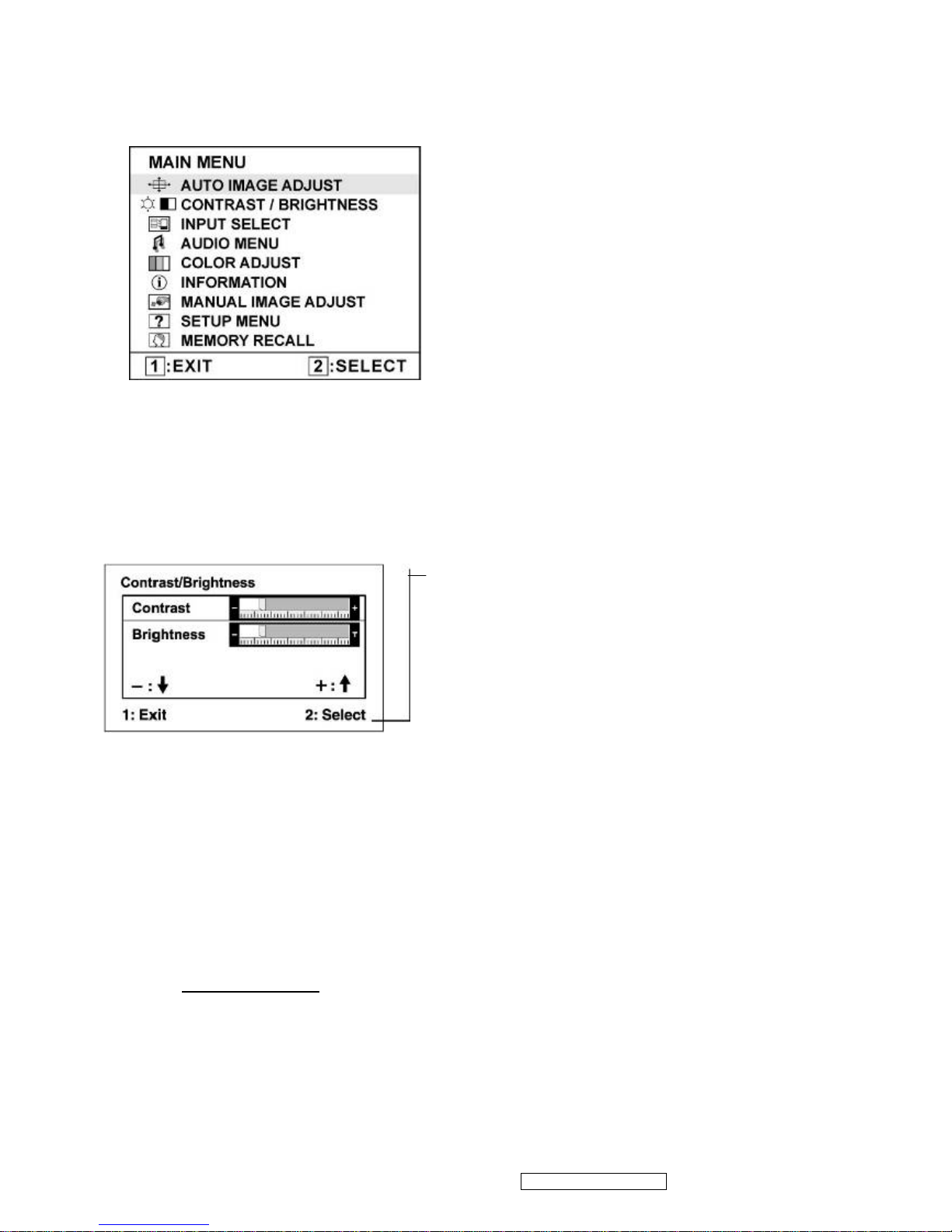
3. After the desired control is selected, press button [2]. A control screen like the one shown
below appears.
The command line at the bottom of the control screen
tells what to do next from this screen. You can toggle
between control screens, adjust the selected option, or
exit the screen.
4. To adjust the setting, press the up ▼ or ▲ down T buttons.
5. To save the adjustments and exit the menu, press button [1] twice.
The following tips may help you optimize your display:
• Adjust the computer's graphics card so that it outputs a 1280 x 1024 @ 60Hz video signal to the
LCD display. (Look for instructions on “changing the refresh rate” in the graphics card's user
guide.)
• If necessary, make small adjustments using H. POSITION and V. POSITION until the screen
image is completely visible. (The black border around the edge of the screen should barely
touch the illuminated “active area” of the LCD display.)
Page 13
ViewSonic Corporation Confidential - Do Not Copy VA712-2_ VA712b-2
10
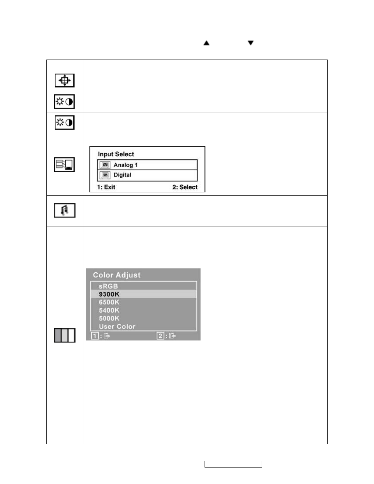
Main Menu Controls
Adjust the menu items shown below by using the up and down buttons.
Control Explanation
Auto Image Adjust sizes and centers the screen image automatically.
Contrast adjusts the difference between the image background (black level)
and the foreground (white level).
Brightness adjusts background black level of the screen image.
Input Select allows the user to toggle between an analog and a digital signal.
Audio Adjust
Volume increases the volume, decreases the volume, and mutes the audio.
Mute temporarily silences audio output.
Color Adjust provides several color adjustment modes, including preset color
temperatures and a User Color mode which allows independent adjustment of
red (R), green (G), and blue (B). The factory setting for this product is 6500K
(6500 Kelvin).
9300K-Adds blue to the screen image for cooler white (used in most office
settings with fluorescent lighting).
6500K-Adds red to the screen image for warmer white and richer red.
5400K-Adds green to the screen image for a darker color.
5000K-Adds blue and green to the screen image for a darker color.
User Color Individual adjustments for red (R), green (G), and blue (B).
1. To select color (R, G or B) press button [2].
2. To adjust selected color, press ▼ and ▲.
Important: If you select RECALL from the Main Menu when the product is
set to a Preset Timing Mode, colors return to the 6500K factory preset.
Page 14

ViewSonic Corporation Confidential - Do Not Copy VA712-2_ VA712b-2
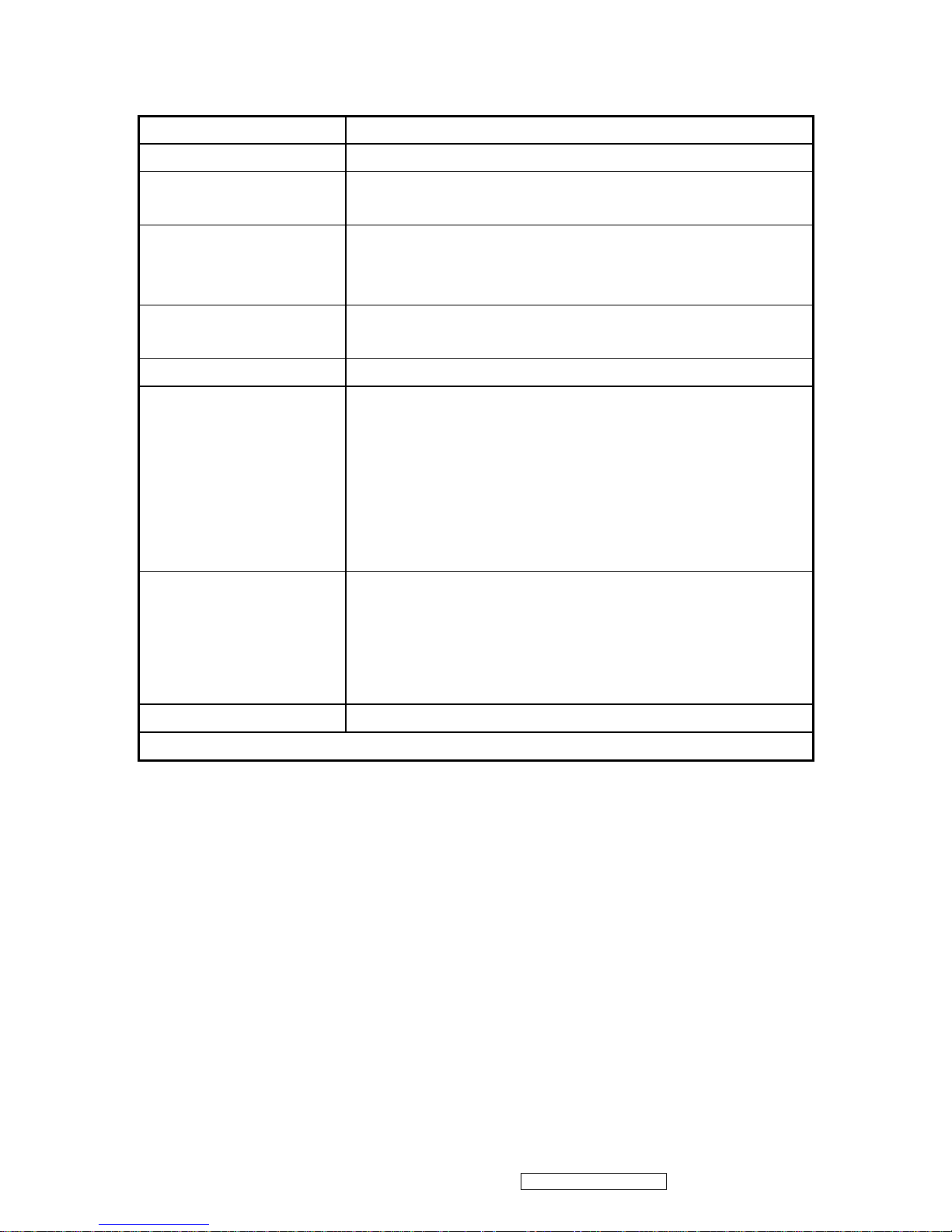
11
Information displays the timing mode (video signal input) coming from the
graphics card in the computer, the LCD model number, the serial number, and
the ViewSonic® website URL. See your graphics card’s user guide for
instructions on changing the resolution and refresh rate (vertical frequency).
NOTE: VESA 1280 x 1024 @ 60Hz (recommended) means that the resolution
is 1280 x 1024 and the refresh rate is 60 Hertz.
Manual Image Adjust Sub-menu
H. Size (Horizontal Size) adjusts the width of the screen image.
H./V. Position (Horizontal/Vertical Position) moves the screen image left or
right and up or down.
Fine Tune sharpens the focus by aligning text and/or graphics with pixel
boundaries.
NOTE: Try Auto Image Adjust first.
Sharpness adjusts the clarity and focus of the screen image.
Setup Menu displays the menu shown below:
Page 15

ViewSonic Corporation Confidential - Do Not Copy VA712-2_ VA712b-2
12
Language Select allows the user to choose the language used in the menus
and control screens.
Resolution Notice allows the user to enable or disable this notice.
If you enable the Resolution Notice shown above and your computer is set at a
resolution other than 1280 x 1024, the following screen appears.
OSD Position allows the user to move the OSD menus and control screens.
OSD Timeout sets the length of time the OSD screen is displayed. For
example, with a “30 second” setting, if a control is not pushed within 30
seconds, the display screen disappears.
OSD Background allows the user to turn the OSD background On or Off.
Memory Recall returns the adjustments back to factory settings if the display
is operating in a factory Preset Timing Mode listed in the Specifications of this
manual.
Page 16
ViewSonic Corporation Confidential - Do Not Copy VA712-2_ VA712b-2
13
SHORT CUTS FUNCTION FROM THE BUTTONS
[1] Main Menu
[2] Auto Image Adjust
[▼] or [▲]
To immediately activate Contrast menu. It should be
change to Brightness OSD by push button [2]
[▼] + [▲]
Recall Contrast or Brightness while in the Contrast or
Brightness adjustment, or recall both of Contrast and
Brightness when the OSD is not open.
[1] + [2]
Toggle 720x400 and 640x400 mode when input 720x400
or 640x400 mode
[1] + [▼] + [▲] White Balance (Not shown on user’s guide)
[1] + [▼]
• Power Lock: Press and hold “[2], & ▼” for 10 seconds. If
the power button is pressed the message Power Button
Locked will display for 5 seconds. With or without this
setting, after a power failure, your LCD display’s power
will automatically turn ON when power is restored.
• Power Unlock: Press and hold “[2], & ▼” again for 10
seconds.
[1] + [▲]
• OSD Lock: Press and hold "[1], & (▲)" for 10 seconds. If
any buttons are pressed the message OSD Locked will
display for 5 seconds.
• OSD Unlock: Press and hold “[1], & ▲” again for 10
seconds.
[;U] Volume mute on/off
Remark : All the short cuts function are only available while OSD off
Page 17
ViewSonic Corporation Confidential - Do Not Copy VA712-2_ VA712b-2
14
4. Circuit Description
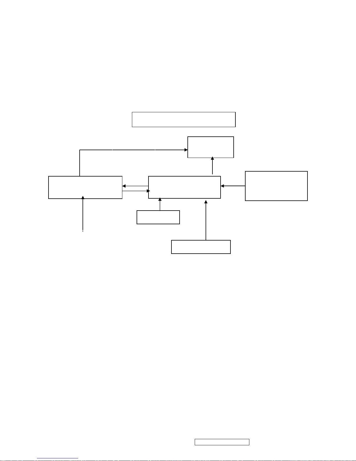
4.1 LCD MONITOR DESCRIPTION
The LCD MONITOR will contain a Main Board, an Power Board, Key Board which house the flat
panel control logic, brightness control logic and DDC.
The Power Board will provide AC to DC Inverter voltage to drive the backlight of panel and the
Main Board chips each voltage.
Power Board
(Include: adapter, inverter)
Flat Panel and
CCFL backlight
Main Board
Key Board
RS232 Connector
For white balance
adjustment in factory
mode
HOST Computer
CCFL Drive.
AC-IN
100V-240V
Video signal, DDC
Monitor Block Diagram
Page 18
ViewSonic Corporation Confidential - Do Not Copy VA712-2_ VA712b-2
15
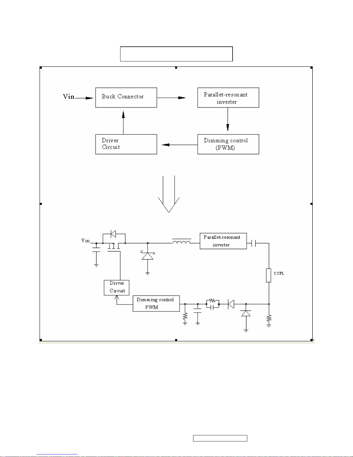
4.2 POWER BLOCK FUNCTION DESCRIPTION
Inverter Block Function
Page 19
ViewSonic Corporation Confidential - Do Not Copy VA712-2_ VA712b-2
16
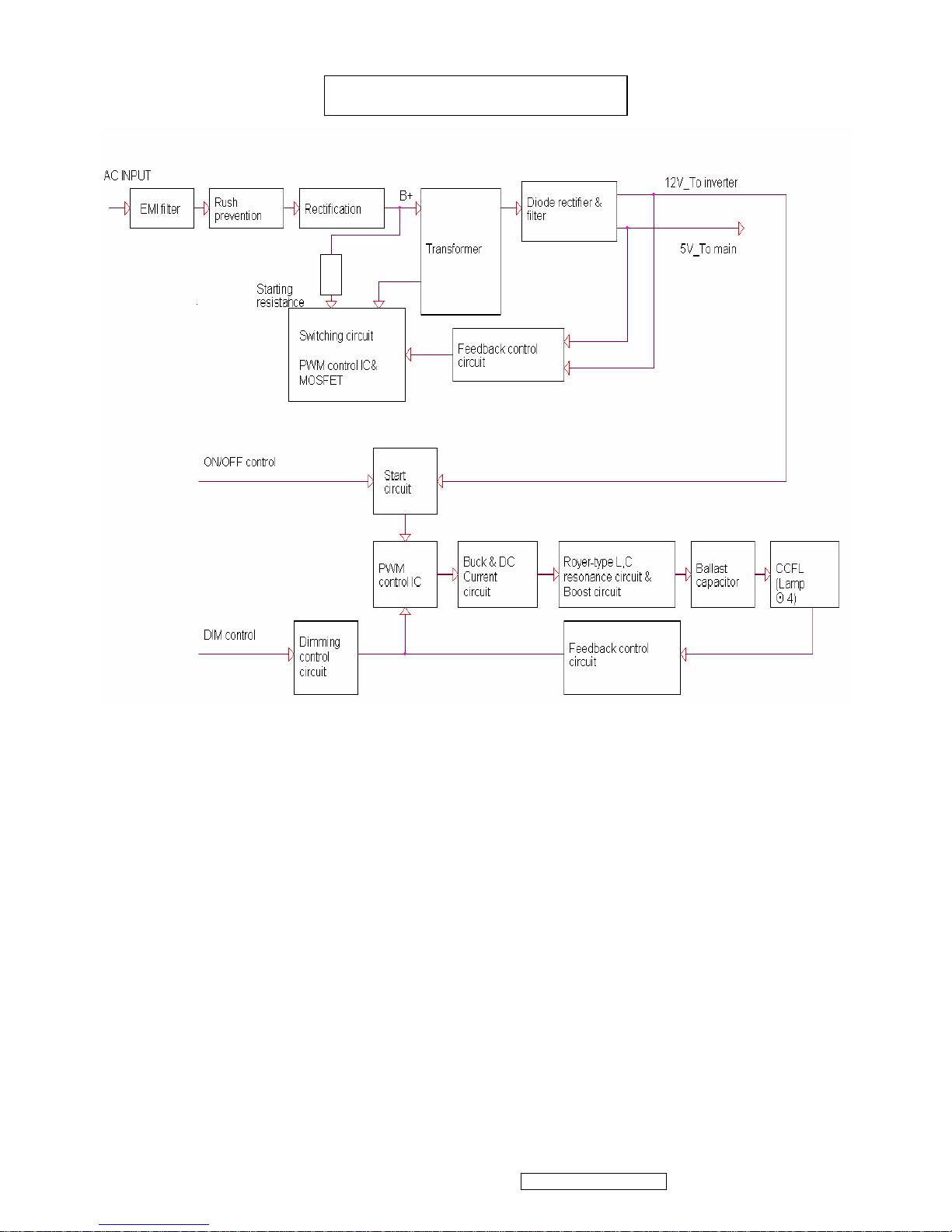
Power Block Function
4.3 Function Test and Alignment Procedure
All Modes Reset
You should do “All Mode Reset” (Refer to Chapter III-3. Hot Keys for Function
Controls) first. This action will allow you to erase all end-user’s settings and restore
the factory defaults.
Auto Image Adjust
Please select and enter “Auto Image Adjust” function on Main Menu to see if it is
workable. The “Auto Image Adjust” function is aimed to offer a better screen quality
by built-in ASIC. For optimum screen quality, the user has to adjust each function
manually.
Firmware
Test Pattern: Burn In Mode (Refer to Chapter III-3. Hot Keys for Function Controls)
- Make sure the F/W is the latest version.
DDC
Test Pattern: EDID program
Page 20

Make sure it can pass test program.
Fine Tune and Sharpness
Test Signal: 1280*1024@60Hz
Test Pattern: Line Moire Pattern
Check and see if the image has noise and focus performs well. Eliminate visual
line bar.
If not, readjust by the following steps:
(a)Select and enter “Fine Tune” function on “Manual Image Adjust” to adjust the
image to eliminate visual wavy noise.
(b)Then, select and enter “Sharpness” function to adjust the clarity and focus of
the screen image.
Boundary
Test Signal: 1280*1024@60Hz
Test Pattern: Horizontal & Vertical Line Thickness Pattern
Check and see if the image boundary is within the screen frame.
If not, readjust by the following steps:
(a)Select and enter “Manual Image Adjust” function on OSD Main Menu.
(b)Then, select and enter “Horizontal Size” or “Horizontal/Vertical Position” function
to adjust the video boundary to be full scanned and within screen frame.
White Balance
Test Signal: 640*480@60Hz
Test Pattern: White and Black Pattern
1.5.8 R, G, B, Colors Contrast
Test Signal: 1280*1024@60Hz
Test Pattern: R, G, B, Color Intensities Pattern and 16 Gray Scale Pattern
- Check and see if each color is normal and distinguishable.
- If not, please return the unit to repair area.
Screen Uniformity and Flicker
Test Signal: 1280*1024@60Hz
Test Pattern: Full White Pattern
- Check and see if it is in normal condition.
1.5.10 Dead Pixel and Line
Test Signal: 1280*1024@60Hz
Test Pattern: Dark and White Screen Pattern
- Check and see if there are dead pixels on LCD panel with shadow gauge and
filter film.
- The total numbers and distance of dead pixels should be compliant with the
spec.
Mura
Test Pattern: White, RGB, Black, & Grey
Test Tool: 10% ND Filter
- Check if the Mura can pass 10% ND Filter.
Audio
Test Signal: Voice signal (optional, depend on model)
Test Pattern: liberty
- Make sure there is audio output.
- Make sure that audio function (volume 80%) is working without noise and
ViewSonic Corporation Confidential - Do Not Copy VA712-2_ VA712b-2
17
Page 21

resonance.
- Make sure that the sound of right and left speakers are in balance.
Check for Secondary Display Modes
Test Signal:
Analog: 640*350@70Hz; 640*480@60/67/72/75/85Hz;
720*400@70Hz; 800*600@56/60/72/75/85Hz;
832*624@75Hz, 1024*768@60/70/72/75/85Hz;
1280*1024@60/75Hz
Digital: 640*350@70Hz; 640*480@60/72/75/85Hz;
720*400@70Hz; 800*600@56/60/72/75/85Hz;
1024*768@60/70/72/75/85Hz; 1152*870@75Hz,
1280*720@60Hz, 1280*1024@60Hz
- Normally when the primary mode 1280*1024@60Hz is well adjusted and
compliant with the specification, the secondary display modes will also be
compliant with the spec. But we still have to check with the general test pattern to
make sure every secondary is compliant with the specification.
-
All Modes Reset
After final QC step, we have to erase all saved changes again and restore the
factory defaults. You should do “All Mode Reset” again.
Power Off Monitor
Turn off the monitor by pressing “Power” button.
ViewSonic Corporation Confidential - Do Not Copy VA712-2_ VA712b-2
18
Page 22
4.4 INTRODUCTION OF IC
RTD2523B-LF(U401): integrate ADC, OSD, TMPS, RSDS TX, LVDS TX, convert
analog RGB into digital and room and shrink scaling output to LCD panel.
PIN Function:
AIC1084-33PM (U701): DC power convert, used to 5v convert 3.3v.
Pin Symbol Description
127 XO Crystal OSC output
128 XI Reference clock input from external crystal or from
single-ended CMOS/TTL OSC(3.3V tolerance)
50
DDCSCL1(ADC) Open drain(Internal 75K pull high)
51
DDCSDA1(ADC) Open drain(Internal 75K pull high)
121
DDCSCL2(DVI) Open drain(Internal 75K pull high)
120
DDCSDA2(DVI) Open drain(Internal 75K pull high)
123 RESET_OUT Reset out Open drain( internal 75KOhm high)
110/48 COUT Crystal out
124 33VRST_REF Reference 3.3V for Reset Out
109 33VPNLOUT
Panel on/off switch out (Max current driving 1A)
58 BJT_B Embedded regulator P type BJT control pin out
5 TMDS_TST TMDS_TEST Pin;
Power-on-latch for host interface type.
7/13 TMDS_VDD
TMDS power(3.3V)
6 REXT Impedance Match Reference.
49/112 PWM2
4/48/111 PWM1
3/5/122 PWM0
4 BYPASS For External Bypass Capacitor
125 DPLL_VDD
Power for digital PLL(3.3V)
2 APLL_VDD
Power for multi-phase PLL(3.3V)
3 PLL_TEST1 Test Pin 1;Power-on-latch for MCU crystal location
4 PLL_TEST2 Test Pin 2;Power-on-latch for crystal in frequency
56/118 SCSB
Serial control I/F chip select(Open drain)
57/119 SCLK
Serial control I/F clock(Open drain)
59/83/108 Pad 3.3V Power PVCC
47/116 Digital 1.8V Power VCCK
21/38 ADC_VDD
ADC Power(1.8V)
40 VCLK Video8 Clock
19 AVSO ADC vertical sync input
5V tolerance
Power from PIN 13
20 AHSO ADC horizontal sync input
Adjustable Schmidt trigger 5V tolerance
Power from PIN 13
ViewSonic Corporation Confidential - Do Not Copy VA712-2_ VA712b-2
19
Page 23
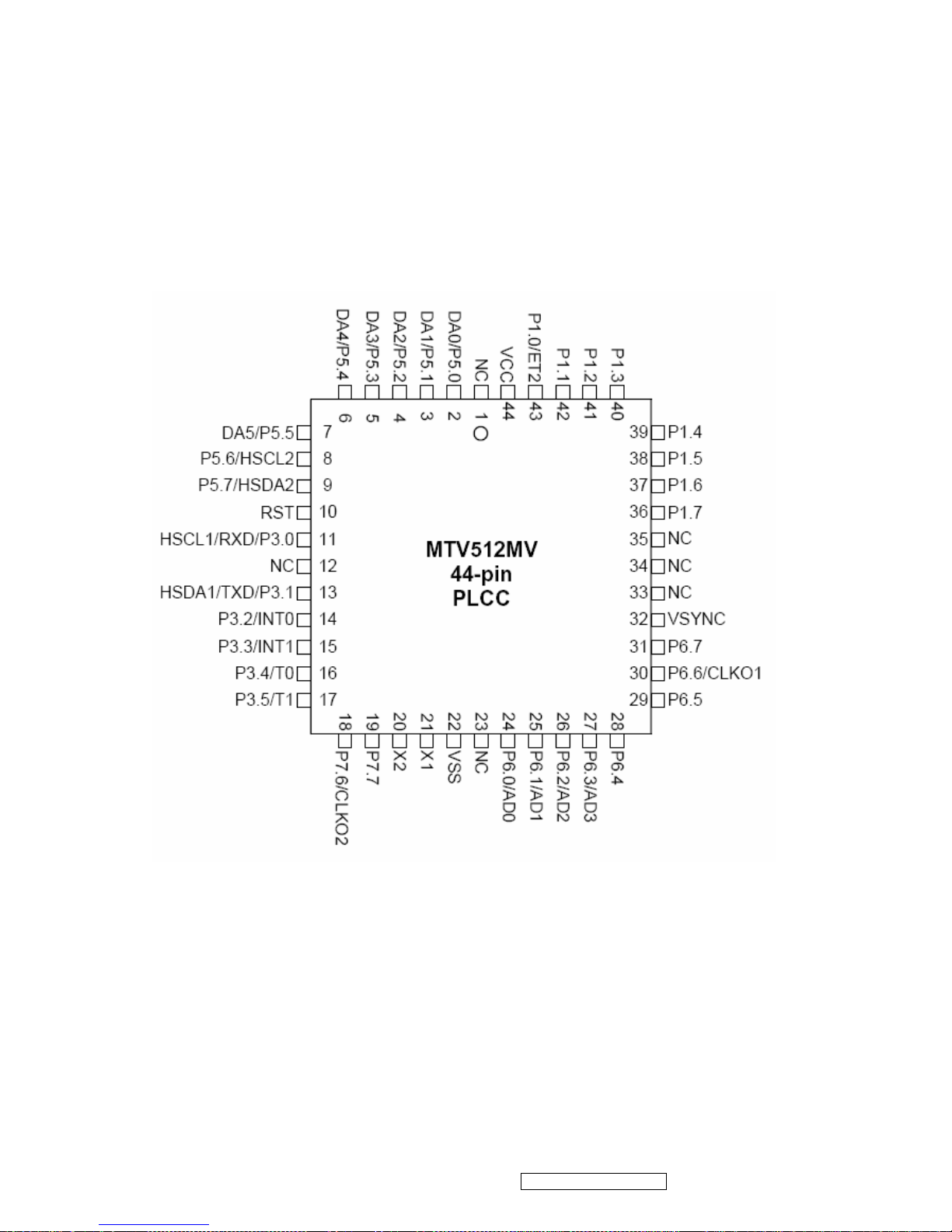
MTV512GMV64 (U402): The MTV512M micro-controller is an 8051 CPU core
embedded device especially tailored for flat panel display applications. It
includes an 8051 CPU core, 768-byte SRAM, 4 channels of 6-bit ADC, 3
external counters/timers, 6 channels of PWM DAC, VESA DDC interface,
and a 64K-byte internal program Flash-ROM memory.
Circuit Diagram
ViewSonic Corporation Confidential - Do Not Copy VA712-2_ VA712b-2
20
Page 24
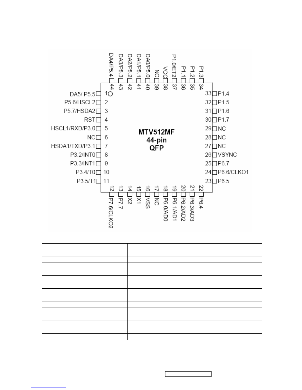
PIN Function
Pin No.
Name
PLCC QFP
DESCRIPTION
NC 1 39
No connection
DA0/P5.0 2 40
PWM DAC output/General purpose I/O (open drain)
DA1/P5.1 3 41
PWM DAC output/General purpose I/O (open drain)
DA2/P5.2 4 42
PWM DAC output/General purpose I/O (open drain)
DA3/P5.3 5 43
PWM DAC output/General purpose I/O (open drain)
DA4/P5.4 6 44
PWM DAC output/General purpose I/O (open drain)
DA5/P5.5 7 1
PWM DAC output/General purpose I/O (open drain)
P5.6/HSCL2 8 2
General purpose I/O/Slave llC1 SCL2(open drain)
P5.7/HSDA2 9 3
General purpose Output/Slave llC1 SCL2(open drain)
RST 10 4
High Active RESET
HSCL1/P3.0/RXD 11 5
Slave IIC clock/General purpose I/O/Rxd (open drain)
HSDA1/P3.1/RXD 13 7
Slave IIC clock/General purpose I/O/Txd (open drain)
P3.2/INT0 14 8
General purpose I/O/External interrupt 0(Standard 8051)
ViewSonic Corporation Confidential - Do Not Copy VA712-2_ VA712b-2
21
Page 25

P3.3/INT1 15 9
General purpose I/O/External interrupt 1(Standard 8051)
P3.4/T0 16 10
General purpose I/O/T0 Ext. Counter/Timer 0(Standard8051)
P3.5/T1 17 11
General purpose I/O/T1 Ext. Counter/Timer 1(Standard8051)
P7.6/CLKO2 18 12
General purpose I/O/Clock out 2 (CMOS)
P7.7 19 13
General purpose I/O (CMOS)
X2 20 14
Crystal Out
X1 21 15
Crystal In
VSS 22 16
Ground
P6.0/AD0 24 18
General purpose I/O(COMS)/6-bit ADC channel 0 input
P6.1/AD1 25 19
General purpose I/O(COMS)/6-bit ADC channel 1 input
P6.2/AD2 26 20
General purpose I/O(COMS)/6-bit ADC channel 2 input
P6.3/AD3 27 21
General purpose I/O(COMS)/6-bit ADC channel 3 input
P6.4 28 22
General purpose I/O(COMS)
P6.5 29 23
General purpose I/O(COMS)
P6.6/CLKO1 30 24
General purpose I/OCLKO1(COMS)
P6.7 31 25
General purpose I/O(COMS)
VSYNC 32 26
VSYNC input
P1.7 36 30
General purpose I/O(Standard 8051/CMOS)
P1.6 37 31
General purpose I/O(Standard 8051/CMOS)
P1.5 38 32
General purpose I/O(Standard 8051/CMOS)
P1.4 39 33
General purpose I/O(Standard 8051/CMOS)
P1.3 40 34
General purpose I/O(Standard 8051/CMOS)
P1.2 41 35
General purpose I/O(Standard 8051/CMOS)
P1.1 42 36
General purpose I/O(Standard 8051/CMOS)
P1.0/ET2
43
37
General purpose I/O/External Counter/Timer2(Standard
8051/CMOS)
VCC 44 38
3.3V power
TDA7496L (U201): The UTC TDA7496L is a stereo 2W+2W class AB power amplifier,
specially designed for high quality sound, TV and Monitor applications.
Features of the UTC TDA7496L include linear volume control, Stand-by and
mute functions.
Pin Function
ViewSonic Corporation Confidential - Do Not Copy VA712-2_ VA712b-2
22
Page 26

Circuit Diagram
LD7552BS (IC901): PWM control, high-voltage startup current. The circuit unit has
functions such as over-current protection, over-voltage protection, output short-circuit
protection and etc. The function of each pin and the inside circuit diagram are as
follows:
Pin Name Function
1 GND Ground
2 COMP
Voltage feedback pin (same as the COMP pin in UC384X), By
connecting a photo-coupler to close the control loop and achieve the
regulation
3 VCC Supply voltage pin
4 RT
This pin is to program the switching frequency. By connecting a resistor
to ground to set the switching frequency.
6 NC Unconnected pin
7 VCC Supply voltage pin
8 OUT Gate drive output to drive the external MOSFET
ViewSonic Corporation Confidential - Do Not Copy VA712-2_ VA712b-2
23
Page 27

FAN7547A(IC201): The FAN7547A provides all control functions for a current fed
push-pull self oscillation type converter, and also contains voltage. Typical
operating frequency range is between 30kHz depending on the CCFL(Cold
Cathode Fluorescent Lamp) and the transformer’s characteristics:
NO. Name Function Description NO. Name Function Description
1 GNDT Ground 8 FB Feedback Input
2 Vds Dimming Voltage Input 9 COMP Error Amplifier Output
3 Vref Reference Voltage 10 S/S Soft Start
4 Vms Dimming Mode Selection 11 OSC Main Ct
5 Rct
Burst Dimming Frequency
Set
12 Vcc Supply Voltage
6 OLP Open Lamp Protection 13 Vcc1 Output Drive Source Voltage
7 SDP Shutdown Protection 14 OUT Output Drive
ViewSonic Corporation Confidential - Do Not Copy VA712-2_ VA712b-2
24
Page 28

ViewSonic Corporation Confidential - Do Not Copy VA712-2_ VA712b-2
25
Page 29

ViewSonic Corporation Confidential - Do Not Copy VA712-2_ VA712b-2
26
5. Adjustment Procedure
5.1 ADJUSTMENT CONDITIONS AND PRECAUTIONS
1. Approximately 30 minutes should be allowed for warm up before proceeding.
2. Adjustments should be undertaken only on those necessary elements since most of them
have been carefully preset at the factory.
3. ESD protection is needed before adjustment.
5.2 MAIN ADJUSTMENTS
NO. FUNCTIONS DESIGNATION
1. White Balance Function Key
2. Geometry Function Key
5.3 ALIGNMENT PROCEDURES
Approximately 30 minutes should be allowed for warm up before proceeding
White-Balance adjustment.
1. Adjust of White Balance
1.)How to do the Chroma-7120 MEM .Channel setting
A、Reference to Chroma 7120 user guide
B、Use “ SC” key and “ NEXT” key to modify xyY value and use “ID” key to modify the TEXT
description Following is the procedure to do white-balance adjust
2.)Setting the color temp. You want
A、MEM.CHANNEL9 ( 9300 color):
9300 color temp. parameter is Wx = 0.283 ±0.02;Wy = 0.298 ±0.02;
Y > 190 cd/m
2 ,
B、MEM.CHANNEL10 ( 6500 color):
6500 color temp. parameter is Wx = 0.313±0.02;Wy = 0.329 ±0.02;
Y > 260 cd/m
2,
C、MEM.CHANNEL 11 ( 5400 color):
5400 color temp. parameter is Wx = 0.335±0.02;Wy = 0.350 ±0.02;
Y > 210 cd/m
2,
D、MEM.CHANNEL 12 ( 5000 color):
5000 color temp. parameter is Wx = 0.346±0.02;Wy = 0.359 ±0.02;
Y > 210 cd/m
2
Page 30

ViewSonic Corporation Confidential - Do Not Copy VA712-2_ VA712b-2
27
E、MEM.CHANNEL13 ( SRGB color):
SRGB color temp. parameter is Wx = 0.313±0.02;Wy = 0.329 ±0.02;
Y > 220 cd/m2,
3.)Into factory mode of VA712b-2
A、First Power off, then press Switch 2 button along with press Power button will activate the
factory mode, then MCU will do AUTO LEVEL automatically. Meanwhile press MENU the OSD
screen will located at LEFT TOP OF PANEL.
4.)Bias adjustment :
Set the Contrast to 70
Adjust the Brightness to 100.
5.)Gain adjustment :
Move cursor to “-F-” and press MENU key
A、Adjust 9300 color-temperature
(1)、Switch the Chroma-7120 to RGB-Mode (with press “MODE” button )
(2)、Switch the MEM. channel to Channel 9 ( with up or down arrow on Chroma 7120 )
(3)、The LCD-indicator on Chroma 7120 will show x = 0.283 ±0.02, y =0.298 ±0.02, Y >
250 cd/m2
(4)、Adjust the RED of color1 on factory window until chroma 7120 indicator reached the
value R=100
(5)、Adjust the GREEN of color1 on factory window until Chroma 7120 indicator reached the
value G=100
(6)、Adjust the BLUE of color1 on factory window until Chroma 7120 indicator reached the
value B=100
(7)、Repeat above procedure ( item 4,5,6) until Chroma 7120 RGB value meet the
tolerance =100±5
B、Adjust 6500 color-temperature
(1)、Switch the chroma-7120 to RGB-Mode (with press “MODE” button )
(2)、Switch the MEM .channel to Channel 10( with up or down arrow on Chroma 7120 )
(3)、The LCD-indicator on Chroma 7120 will show x = 0.313 ±0.02, y = 0.329 ±0.02, Y>260
cd/m2
(4)、Adjust the RED of color3 on factory window until Chroma 7120 indicator reached the
value R=100
(5)、Adjust the GREEN of color3 on factory window until Chroma 7120 indicator reached the
value G=100
Page 31

ViewSonic Corporation Confidential - Do Not Copy VA712-2_ VA712b-2
28
(6)、Adjust the BLUE of color3 on factory window until Chroma 7120 indicator reached the
value B=100
(7)、Repeat above procedure ( item 4,5,6) until Chroma 7120 RGB value meet the
tolerance =100±5
C、Adjust 5400 color-temperature
(1) Switch the chroma-7120 to RGB-Mode (with press “MODE” button )
(2)、Switch the MEM .channel to Channel 11( with up or down arrow on Chroma 7120 )
(3)、The LCD-indicator on Chroma 7120 will show x = 0.335 ±0.02, y = 0.350 ±0.02, Y>210
cd/m2
(4)、Adjust the RED of color3 on factory window until chroma 7120 indicator reached the value
R=100
(5)、Adjust the GREEN of color3 on factory window until Chroma 7120 indicator reached the
value G=100
(6)、Adjust the BLUE of color3 on factory window until Chroma 7120 indicator reached the
value B=100
(7)、Repeat above procedure ( item 4,5,6) until Chroma 7120 RGB value meet the
tolerance =100±5
D、Adjust 5000 color-temperature
(1) Switch the chroma-7120 to RGB-Mode (with press “MODE” button )
(2)、Switch the MEM .channel to Channel 11( with up or down arrow on Chroma 7120 )
(3)、The LCD-indicator on Chroma 7120 will show x = 0.346 ±0.02, y = 0.359 ±0.02, Y>210
cd/m
2
(4)、Adjust the RED of color3 on factory window until chroma 7120 indicator reached the value
R=100
(5)、Adjust the GREEN of color3 on factory window until Chroma 7120 indicator reached the
value G=100
(6)、Adjust the BLUE of color3 on factory window until Chroma 7120 indicator reached the
value B=100
(7)、Repeat above procedure ( item 4,5,6) until Chroma 7120 RGB value meet the
tolerance =100±5
E、Adjust SRGB color-temperature
(1)、Switch the chroma-7120 to RGB-Mode (with press “MODE” button )
(2)、Switch the MEM .channel to Channel 10( with up or down arrow on chroma 7120 )
(3)、The LCD-indicator on chroma 7120 will show x = 0.313 ±0.02, y = 0.329 ±0.02, Y>220
cd/m
2
Page 32

ViewSonic Corporation Confidential - Do Not Copy VA712-2_ VA712b-2
29
(4)、Adjust the RED of color3 on factory window until Chroma 7120 indicator reached the
value R=100
(5)、Adjust the GREEN of color3 on factory window until Chroma 7120 indicator reached the
value G=100
(6)、Adjust the BLUE of color3 on factory window until Chroma 7120 indicator reached the
value B=100
(7)、Repeat above procedure ( item 4,5,6) until Chroma 7120 RGB value meet the tolerance
=100±5
E、Press reset key and Turn the Power-button “off to on” to quit from factory mode.
2. Geometry
1).Set cross-hatch pattern and preset timing as timing table listed.
2).Change to each mode in turn and wait for the monitor finish auto-alignment and save
press before change to next mode.
3).Until all of modes are adjusted, exit OSD menu and press POWER OFF to exit factory
mode.
5.4 Factory Defaults
Item Defaults Item Defaults
Contrast 70% OSD H. Position 50%
Brightness 100% OSD V. Position 50%
Volume 50% OSD Time Out 15 Sec
Color Temperature 6500K Resolution Notice Enable
Sharpness 33% OSD background Enable
720X400/640X400 720X400
5.5 Function Test
1 Product: 17” LCD Monitor
2 Test Equipment: Color Video Signal & Pattern (or PC with SXGA resolution and a
sound card)
3 Test Condition: Before function test and alignment, each LCD Monitor should be
warmed up for at least 30 minutes with the following conditions:
(a)In room temperature,
(b) With full-white screen, RGB, and Black
(c) With cycled display modes,
640*480 (H=43.27kHz, V=85Hz)
800*600 (H=53.7kHz, V=85Hz)
1024*768 (H=68.67kHz, V=85Hz)
1280*1024 (H=79.97kHz, V=75Hz)
Page 33

4 Test Display Modes & Pattern
Compatible Modes
Analog Digital
640 x 350 @ 70Hz, 31.5kHz
640 x 400 @ 70Hz, 31.5kHz
640 x 480 @ 60Hz, 31.5kHz
640 x 480 @ 67Hz, 35.0kHz
640 x 480 @ 72Hz, 37.9kHz
640 x 480 @ 75Hz, 37.5kHz
720 x 400 @ 70Hz, 31.5kHz
800 x 600 @ 56Hz, 35.1kHz
800 x 600 @ 60Hz, 37.9kHz
800 x 600 @ 75Hz, 46.9kHz
800 x 600 @ 72Hz, 48.1kHz
832 x 624 @ 75Hz, 49.7kHz
1024 x 768 @ 60Hz, 48.4kHz
1024 x 768 @ 70Hz, 56.5kHz
1024 x 768 @ 72Hz, 58.1kHz
1024 x 768 @ 75Hz, 60.0kHz
1280 x 1024 @ 60Hz, 63.4kHz
1280 x 1024 @ 75Hz, 79.97kHz
1280x 720 @ 60Hz, 45kHz
Function Test Display Pattern
Item Test Content Pattern Specification Remark
1
Frequency &
Tracking
Fine Line Moire
Eliminate visual wavy
noise.
Figure 1
2
Contrast/Bright
ness
16 Gray Scale
16 gray levels sh should
be distinguishable.
Figure 2
3 Boundary
Horizontal&Vertical
Thickness
Horizontal and Vertical
position of video should
be adjustable to be
within the screen frame.
Figure 3
4
RGB Color
Performance
RGB Color Intensities
Contrast of each R, G,
B, color should be
normal.
Figure
4,5,6
5
Screen
Uniformity &
Flicker
Full White
Should be compliant
with the spec.
Figure 7
6
Dead
Pixel/Line
White Screen & Dark
Screen
The numbers of dead
pixels should be
compliant with the spec.
Figure 7,8
7 White Balance White & Black Pattern
The screen must have
the pure white and black
pattern, no other color.
Figure 9
ViewSonic Corporation Confidential - Do Not Copy VA712-2_ VA712b-2
30
Page 34

Fine Line Morie Pattern (Figure1) Gray Scale Pattern (Figure2)
Horizontal & Vertical Thickness Pattern R. Color Pattern (Figure 4)
(Figure 3)
G. Color Pattern (Figure 5) B. Color Pattern (Figure 6)
ViewSonic Corporation Confidential - Do Not Copy VA712-2_ VA712b-2
31
Page 35

Full White Pattern (Figure 7) Dark Screen Pattern (Figure 8)
Black-White Pattern (Figure 9)
ViewSonic Corporation Confidential - Do Not Copy VA712-2_ VA712b-2
32
Page 36

5.6 Firmware Upgrade Procedure
When you receive the returned monitor, please check whether the firmware version is
the latest. If not, please do the following procedures to upgrade it to the latest version.
1 Equipment Needed
- VA712-2/VA712b-2 Monitor
- Fixture for Firmware Upgrade
- Power Adapter (P/N: 47.58201.001) *1 for Fixture
- VGA Cable (P/N: 42.59901.003) *1(Pin 4, 11 should be connected to GND)
- PC (Personal Computer)
- LPT Cable (P/N: 42.59906.001) *1
- Firmware Upgrade Program
- One additional monitor for checking the program execution
2 Setup Procedure
2.1 Connect P1 of Fixture with printer port of PC by LPT Cable.
2.2 Connect P2 of Fixture with VA712-2/VA712b-2 Monitor by VGA Cable.
2.3 Connect Power Cord to VA712-2/VA712b-2 Monitor.
2.4 Connect P3 to the Signal Generator (eg.Chroma2326) for verifying it after the
operation being completed.
2.5 Connect PC to the additional monitor.
ViewSonic Corporation Confidential - Do Not Copy VA712-2_ VA712b-2
33
Page 37

3 Firmware Upgrade Procedure
Step 1. Let VA712-2/VA712b-2 set to be connected with AC cable and VGA cable.
Step 2.Execute the MSstar ISP tool.
ViewSonic Corporation Confidential - Do Not Copy VA712-2_ VA712b-2
34
Page 38

Step 3. Click “Create Security File” button. Open a new window to key in security code.
Step 4.Set “Command NO” to 4
,and key in security code :“94,94,ac,ca,53” to shown as
following, then press “OK” button to close window.
ViewSonic Corporation Confidential - Do Not Copy VA712-2_ VA712b-2
35
Page 39

Step 5. Click dropdown listbox for MTV type, select the “MTV512M64” viewed on your
set.
Step 6. Click “Load MCU File” button. Select the object bincode on your corresponding
directory.
Step 7. Click “确定” button to finish the selection of bincode.
ViewSonic Corporation Confidential - Do Not Copy VA712-2_ VA712b-2
36
Page 40

Step 8. Select “Auto” optionbutton, then execute the flashing action by clicking the
“RUN” button.
Step 9. If the flashing F/W has been completed, the message of “Check MCU CRC OK”
on the right TextBox means the Host verify ok for the progress of program.
ViewSonic Corporation Confidential - Do Not Copy VA712-2_ VA712b-2
37
Page 41

Step 10. Unplug and replug power cord of VA712-2/VA712b-2 set and then check the
OSD operation and image on srceen.
Step 11. At last, do “Memory Recall.”
3.2 Setup Procedure
3.2.1 Connect P2 and monitor of Fixture with VGA ports of VA712-2/VA712b-2 by VGA
Cable.
3.2.2 Connect P3 of Fixture with DVI port of VA712b-2 by DVI-DVI Cable.
3.2.3 Connect P1 of Fixture with Printer port of PC by LPT Cable.
3.2.4 Plug Power Adapter to Fixture.
3.2.5 Connect Power Cord to VA712-2/VA712b-2 Monitor.
3.2.6 Connect PC to the additional monitor.
P3:DVI-DVI Cable
JP1: Power Adapter
P2: VGA Cable
P1:to LTP Cable
ViewSonic Corporation Confidential - Do Not Copy VA712-2_ VA712b-2
38
Page 42

3.3 DDC Key In Procedure
Sep1.Select and execute DDC Key In program
ViewSonic Corporation Confidential - Do Not Copy VA712-2_ VA712b-2
39
Page 43

Sep2:Inpute the S/N and execute “Enter”
ViewSonic Corporation Confidential - Do Not Copy VA712-2_ VA712b-2
40
Page 44

ViewSonic Corporation Confidential - Do Not Copy VA712-2_ VA712b-2
41
Page 45

Sep3:Key the “Enter” and write the data
ViewSonic Corporation Confidential - Do Not Copy VA712-2_ VA712b-2
42
Page 46

Sep4:If ddc program OK and show “data compare ok”
ViewSonic Corporation Confidential - Do Not Copy VA712-2_ VA712b-2
43
Page 47

ViewSonic Corporation Confidential - Do Not Copy VA712-2_ VA712b-2
44
Disassemble Process
1.1. Units Disassemble Process
1.1.1. Tools
Glove
Big cross screwdriver
Small cross screwdriver
Prize equipment or abandoned IC card
Screw box
Cushion
Six angle sleeve spanner
1.1.2. Disassemble process
1、 Tide up the worktable, spread straight cushion, put the monitor on it, the front side
adown.(Picture 1, 2)
2、 Disassemble the 4 screws that fix the stand, remove the stand..(Picture 3, 4)
3、 Disassemble the fix screws of the back cover.(Picture 5)
4、 Use equipment or abandoned IC card to prize up the bezel through the bottom flute,
as showed in the following the picture 6,7, and rip up the back cover downwards.( as
showed in the following the picture 8,9,10)
5、 Disassemble the 4 screw M3*6MM through six angle sleeve spanner, showed in the
following picture 11.
6、 Disassemble the 4 fixed screws in the shield, remove the shield as the direction
arrowhead showed, refer to the following picture 12.
7、 Disassemble the 4 screws and 4 pins of the PWPC board, remove the PWPC
board.(symbolized the following picture 13 with red color)
8、 Disassemble the 3 screws and 4 pins of the main board, remove the main board.
(symbolized the following picture 13 with blue color)
9、 Disassemble the 2 screws of the audio board, remove the audio board. (symbolized
the following picture 13 with green color)
10、 Disassemble the 3 screws and connect pins of the Key board, remove the Key board,
refer to the following picture 14,15 .
11、 Disassemble the 2 fixed screws of the main frame, and remove the bezel, as showed
in the following the picture 16,17.
12、 Disassemble the 2 fixed screws of the panel, remove the main frame, as showed in
the following the picture 18,19,20. Do not damage the cable of the panel.
13、 That’s all. The disassemble process of the unit is over.
Page 48

ViewSonic Corporation Confidential - Do Not Copy VA712-2_ VA712b-2
45
1.1.3 Show pictures:
(Picture 1) (Picture 2)
(Picture 3) (Picture 4)
(Picture 5) (Picture 6)
Page 49

ViewSonic Corporation Confidential - Do Not Copy VA712-2_ VA712b-2
46
(Picture 7) (Picture 8)
(Picture 9) (Picture 10)
(Picture 11) (Picture 12)
Page 50

ViewSonic Corporation Confidential - Do Not Copy VA712-2_ VA712b-2
47
(Picture 13)
(Picture 14)
(Picture 15)
Page 51

ViewSonic Corporation Confidential - Do Not Copy VA712-2_ VA712b-2
48
(Picture 16)
(Picture 17)
(Picture 18)
(Picture 19)
(Picture 20)
Page 52

ViewSonic Corporation Confidential - Do Not Copy VA712-2_ VA712b-2
49
6. Troubleshooting Flow Chart
Page 53

ViewSonic Corporation Confidential - Do Not Copy VA712-2_ VA712b-2
50
7. Recommended Spare Parts List
ViewSonic Model Number: VS10901-1W
Rev: 1a
Serial No. Prefix: PX5
Item ECR/ECN ViewSonic P/N Ref. P/N Location Universal number# Q'ty
1
Accessories:
POWER CORD A-00004962 89G404A18N LS 1PCS
2
Board Assembly:
AUDIO BOARD B-00004963 AUPC780B3P 1PCS
3 CONVERSION BOARD B-00005609 CBPC780KCWV4P 1PCS
4 KEY BOARD B-00005610 KEPC780KE1P 1PCS
5 POWER BOARD B-00005611 PWPC1742CPV2P 1PCS
6
Cabinets:
FRONT PANEL (BEZEL) C-00005612 34G1750AKD B 1PCS
7 REAR COVER C-00005613 34G1751 KR 2B 1PCS
8 BASE ASSY C-00005649 34G1754 KR B 1PCS
9
Cables:
SIGNAL CABLE CB-00003768 89G 728HAA902 1PCS
10 AUDIO CABLE CB-00004972 89G 173 56 31 1PCS
11 WIRE (AUDIO BOARD HARNESS) CB-00005614 95G8014 14 34 1PCS
12 KEY BOARD HARNESS CB-00005615 95G8014 16926 1PCS
13 WIRE HARNESS CB-00005616 95G8018 30910 1PCS
14
Documentation
CARTON LABEL DC-00003727 40G 459709 1B 1PCS
15 H/V WARNING LABEL DC-00003729 40G 459709 4A 1PCS
16 Hg LABEL DC-00003730 40G457B709 1A 1PCS
17 HI-POT LABEL FOR 17-L DC-00003731 40G 459709 5A 1PCS
18 QSG DC-00005617 41G7801709 6A 1PCS
19 CD MANUAL DC-00005618 70G1701709 8A 1PCS
20 S/N LABEL DC-00005635 40G581B709 4A 1PCS
21 MANUAL P/N LABEL DC-00005636 40G 58162435A 1PCS
22 ID LABEL DC-00005637 J40G170T709 1A 1PCS
23 BLUE STICKER-2 DC-00005638 40G581B709 2B 1PCS
24 8ms STICKER DC-00005639 40G581B709 3A 1PCS
25
Electronics:
IC M24C02-WMN6TP E-00003738 56G1133 34 U405 1PCS
26 IC M24C16-WMN6TP E-00004982 56G1133 56 U404 1PCS
27 LCD PANEL E-00005619 750GLC70A7Q 12 1PCS
28 SPEAKER E-00005620 78G 311 8 L 1PCS
29 SPEAKER E-00005621 78G 311 8 R 1PCS
30 IC AMPLIFIER E-TDA749 E-00005622 56G 616 1 U201 1PCS
31 RTD2023L-LF LQFP-48 E-00005650 56G 562115 U403 1PCS
32 AIC1084-33PM TO-263 E-00005651 56G 563 7 U701 1PCS
33 MTV512MV PLCC-44 MYSO E-00005652 56G1125543CA4 U402 1PCS
34
Hardware:
MAIN FRAME HW-00005623 15G8267 1 1PCS
35 HINGE HW-00005624 37G 552 1 1PCS
36 SCREW HW-00005625 M1G 130 6120 4PCS
37 SCREW HW-00005626 M1G 330 4128 4PCS
38 SCREW HW-00005627 M1G1140 6128 1PCS
39 SCREW HW-00005628 M1G1730 6128 3PCS
40 SCREW HW-00005629 M1G1740 12120 4PCS
41 SCREW HW-00005630 Q1G 130 6120 2PCS
42 SCREW HW-00005631 Q1G 330 8 47 1PCS
43 SCREW HW-00005632 Q1G 330 8128 3PCS
44 SCREW HW-00005633 Q1G1030 8128 4PCS
45 SCREW HW-00005634 Q1G1040 10128 3PCS
46
Packing Material:
FOAM EPS(R) P-00005640 44G3783 1 1PCS
47 FOAM EPS(R) P-00005641 44G3783 2 1PCS
48 PE BAG P-00005642 45G 76 28 V3 1PCS
49 PE BAG FOR BASE P-00005643 45G 88606 1PCS
50 PE BAG P-00005644 45G 88607 1PCS
51 EPE BAG P-00005645 45G 88609 B 1PCS
52 BOX P-00005646 J44G3783709 2C 1PCS
53
Plastics: DECO COVER PL-00005647 34G1752 KR B 1PCS
54 STAND PL-00005648 34G1753 KR B 1PCS
Remark 1:
Above listed items are examples, supplier can expand the rows to add more necessary items.
Remark 2: All revised RSPLs with newly added items or any change made should be highlighted and correlated with the ECN/ECR
approved by ViewSonic Corporation. This is to eliminate repeated cross checks of each item between this version and prior
versions.
RECOMMENDED SPARE PARTS LIST (VA712-2)
Description
Page 54

Rev: 1a
Serial No. Prefix: PX7
Item ECR/ECN ViewSonic P/N Ref. P/N Location Universal number# Q'ty
1
Accessories:
POWER CORD A-00003716 89G402A18N LS 1PCS
2
Board Assembly:
AUDIO BOARD B-00004963 AUPC780B3P 1PCS
3 KEY BOARD B-00005610 KEPC780KE1P 1PCS
4 POWER BOARD B-00005611 PWPC1742CPV2P 1PCS
5 CONVERSION BOARD B-00005653 CBPC780KCWV3P 1PCS
6
Cabinets:
FRONT PANEL (BAZEL) C-00005654 34G1750A4Z B 1PCS
7 REAR COVER C-00005655 34G1751 4Z B 1PCS
8 BASE C-00005665 34G1754 4Z B 1PCS
9
Cables:
SIGNAL CABLE CB-00003768 89G 728HAA902 1PCS
10 AUDIO CABLE CB-00004972 89G 173 56 31 1PCS
11 AUDIO BOARD HARNESS CB-00005614 95G8014 14 34 1PCS
12 KEY BOARD HARNESS CB-00005615 95G8014 16926 1PCS
13 WIRE HARNESS CB-00005616 95G8018 30910 1PCS
14
Documentation:
CARTON LABEL DC-00003727 40G 459709 1B 1PCS
15 Hg LABEL DC-00003730 40G457B709 1A 1PCS
16 HI-POT LABEL FOR 17-L DC-00003731 40G 459709 5A 1PCS
17 QSG DC-00005617 41G7801709 6A 1PCS
18 S/N LABEL DC-00005635 40G581B709 4A 1PCS
19 MANUAL P/N LABEL DC-00005636 40G 58162435A 1PCS
20 BLUE STICKER-2 DC-00005638 40G581B709 2B 1PCS
21 8ms STICKER DC-00005639 40G581B709 3A 1PCS
22 CD MANUAL DC-00005656 70G1701709 9B 1PCS
23 ID DC-00005661 J40G170T709 6A 1PCS
24
Electronics:
IC M24C02-WMN6TP E-00003738 56G1133 34 U405 1PCS
25 IC M24C02-WMN6TP E-00003738 56G1133 34 U406 1PCS
26 IC M24C16-WMN6TP E-00004982 56G1133 56 U404 1PCS
27 SPEAKER E-00005620 78G 311 8 L 1PCS
28 SPEAKER E-00005621 78G 311 8 R 1PCS
29 AIC1084-33PM TO-263 E-00005651 56G 563 7 U701 1PCS
30 PANEL E-00005657 750GLC70A7Q 12 B 1PCS
31 RTD2523B-LF PQFP-128 E-00005658 56G 562116 U401 1PCS
32 MTV512MV PLCC-44 MYSO E-00005659 56G1125543CA3 U402 1PCS
33
Hardware:
MAIN FRAEM HW-00005623 15G8267 1 1PCS
34 HINGE HW-00005624 37G 552 1 1PCS
35 SCREW HW-00005625 M1G 130 6120 4PCS
36 SCREW HW-00005626 M1G 330 4128 4PCS
37 SCREW HW-00005627 M1G1140 6128 1PCS
38 SCREW HW-00005628 M1G1730 6128 2PCS
39 SCREW HW-00005629 M1G1740 12120 4PCS
40 SCREW HW-00005630 Q1G 130 6120 2PCS
41 SCREW HW-00005631 Q1G 330 8 47 1PCS
42 SCREW HW-00005633 Q1G1030 8128 4PCS
43 SCREW HW-00005634 Q1G1040 10128 3PCS
44 SCREW HW-00005660 Q1G 330 8128 3PCS
45
Packing Materials:
EPS(R) P-00005640 44G3783 1 1PCS
46 EPS(R) P-00005641 44G3783 2 1PCS
47 PE BAG P-00005642 45G 76 28 V3 1PCS
48 PE BAG FOR BASE P-00005643 45G 88606 1PCS
49 PE BAG P-00005644 45G 88607 1PCS
50 EPE COVER P-00005645 45G 88609 B 1PCS
51
Plastics:
CARTON P-00005662 J44G3783709 1C 1PCS
52 DECO COVER PL-00005663 34G1752 4Z B 1PCS
53 STAND PL-00005664 34G1753 4Z B 1PCS
RECOMMENDED SPARE PARTS LIST (VA712b-2)
Description
ViewSonic Model Number:VS10901-3W
ViewSonic Corporation Confidential - Do Not Copy VA712-2_ VA712b-2
51
Remark 1:
Above listed items are examples, supplier can expand the rows to add more necessary items.
Remark 2: All revised RSPLs with newly added items or any change made should be highlighted and correlated with the ECN/ECR
approved by ViewSonic Corporation. This is to eliminate repeated cross checks of each item between this version and prior
versions.
Page 55

ViewSonic Model Number: VS10901-1W
Rev: 1a
Serial No. Prefix: PX5
Item ViewSonic P/N Ref. P/N Description Location Universal number# Q'ty
1 B-00004963 AUPC780B3P AUDIO BOARD 1
2 B-00005609 CBPC780KCWV4P CONVERSION BOARD 1
3 B-00005610 KEPC780KE1P KEY BOARD 1
4 B-00005611 PWPC1742CPV2P POWER BOARD 1
5 N/A 11G6054 1 PIN CONNECTOR 4
6 N/A 12G 436 2 VESA RUBBER 4
7 N/A 12G8394 1 FOOT PORON 6
8 N/A 15G5786 1 VRSA BRACKET 1
9 N/A 15G8239 1 Kensington bracket 1
10 HW-00005623 15G8267 1 MAIN FRAEM 1
11 N/A 15G8269 1 HINGE BKT 1
12 N/A 23G3178709 4A VSC17-LCD FRONT LOGO 1
13 N/A 23G3178709 6A BIRD LOGO (E015-006) 1
14 N/A 33G4942 X2 B FONCTION BUTTON 1
15 N/A 33G4943 1 POWER LENS 1
16 N/A 33G4944 2 VSC LOGO 1
17 C-00005612 34G1750AKD B BEZEL 1
18 C-00005613 34G1751 KR 2B REAR COVER 1
19 PL-00005647 34G1752 KR B DECO COVER 1
20 PL-00005648 34G1753 KR B STAND BASE 1
21 C-00005649 34G1754 KR B STAND BASE 1
22 HW-00005624 37G 552 1 HINGE 1
23 N/A 40G 45760819A MODEL LABEL 1
24 DC-00003727 40G 459709 1B CARTON LABEL 1
25 DC-00003731 40G 459709 5A HI-POT LABEL FOR 17-LCD 1
26 DC-00005636 40G 58162435A MANUAL P/N LABEL 1
27 N/A 40G 970709 7A ID 1
28 DC-00003730 40G457B709 1A Hg LABEL 1
29 DC-00005638 40G581B709 2B BLUE STICKER-2 1
30 DC-00005639 40G581B709 3A 8ms STICKER 1
31 DC-00005635 40G581B709 4A S/N LABEL 1
32 DC-00005617 41G7801709 6A QSG 1
33 N/A 44G3231502 ELECTRIC COTTON 2
34 P-00005640 44G3783 1 EPS(R) 1
35 P-00005641 44G3783 2 EPS(R) 1
36 P-00005642 45G 76 28 V3 PE BAG 1
37 N/A 45G 77 3 TRANSPARENT SHEET 3
38 P-00005643 45G 88606 PE BAG FOR BASE 1
39 P-00005644 45G 88607 PE BAG 1
40 P-00005645 45G 88609 B EPE COVER 1
41 N/A 50G 600 1 W WHITE PACKING TAPE 4
42 N/A 50G 600 2 HANDLE1 1
43 N/A 50G 600 3 HANDLE2 1
44 N/A 52G 1150 C BLACK TAPE 4
45 N/A 52G 1185 24 TAPE 5
46 N/A 52G 1206 A AL FOIL 3
47 N/A 52G 1207 A AL FOIL 1
48 N/A 52G 1217 VS AL FOIL 2
49 N/A 52G 1901 A AL FOIL 2
50 N/A 52G6019 1 YELLOW TAPE 5
51 N/A 52G6020 1 PROTECT FILM 1
52 N/A 52G8025 11803 MYLAR POWER 1
53 N/A 52G8025 11804 MYLAR SHIELD 1
54 DC-00005618 70G1701709 8A CD MANUAL 1
55 E-00005620 78G 311 8 L SPEAKER 8OHM 2.5W 1
56 E-00005621 78G 311 8 R SPEAKER 8OHM 2.5W 1
57 N/A 85G 722 2 MAIN SHIELD 1
58 CB-00004972 89G 173 56 31 AUDIO CABLE 1
59 CB-00003768 89G 728HAA902 SIGNAL CABLE 1
60 A-00003716 89G402A18N LS POWER CORD 1
61 CB-00005614 95G8014 14 34 HARNESS 14P-14P 50mm 1
62 N/A 95G8014 16 50 HARNESS 16P-12P 165mm 1
63 CB-00005616 95G8018 30910 WIRE HARNESS 1
64 HW-00005625 M1G 130 6120 SCREW 4
65 HW-00005626 M1G 330 4128 SCREW 4
66 HW-00005627 M1G1140 6128 SCREW 1
67 HW-00005628 M1G1730 6128 SCREW 3
68 HW-00005628 M1G1730 6128 SCREW 2
BOM LIST (VA712-2)
ViewSonic Corporation Confidential - Do Not Copy VA712-2_ VA712b-2
52
Page 56

Item ViewSonic P/N Ref. P/N Description Location Universal number# Q'ty
69 HW-00005628 M1G1730 6128 SCREW 3
70 HW-00005629 M1G1740 12120 SCREW 4
71 HW-00005630 Q1G 130 6120 SCREW 2
72 N/A Q1G 330 8128 SCREW 3
73 N/A Q1G 330 8128 SCREW 2
74 N/A Q1G 330 10 47 SCREW 1
75 HW-00005633 Q1G1030 8128 SCREW 4
76 HW-00005634 Q1G1040 10128 SCREW 3
77 E-00005619 750GLC70A7Q 12 CLAA170EA07Q 17" LCD PAN 1
ViewSonic Corporation Confidential - Do Not Copy VA712-2_ VA712b-2
53
Page 57

ViewSonic Model Number: VS10901-3W
Rev: 1a
Serial No. Prefix: PX7
Item ViewSonic P/N Ref. P/N Description Location Universal number# Q'ty
1 B-00004963 AUPC780B3P AUDIO BOARD 1
2 B-00005653 CBPC780KCWV3P CONVERSION BOARD 1
3 B-00005610 KEPC780KE1P KEY BOARD 1
4 B-00005611 PWPC1742CPV2P POWER BOARD 1
6 N/A 11G6054 1 PIN CONNECTOR 4
7 N/A 12G 436 1 VESA RUBBER 4
8 N/A 12G8394 1 FOOT PORON 6
9 N/A 15G5786 1 VRSA BRACKET 1
10 N/A 15G8239 1 Kensington bracket 1
11 HW-00005623 15G8267 1 MAIN FRAEM 1
12 N/A 15G8269 1 HINGE BKT 1
13 N/A 23G3178709 4A VSC17-LCD FRONT LOGO 1
14 N/A 23G3178709 6A BIRD LOGO (E015-006) 1
15 N/A 33G4942 X2 B FONCTION BUTTON 1
16 N/A 33G4943 1 POWER LENS 1
17 N/A 33G4944 1 VSC LOGO 1
18 C-00005654 34G1750A4Z B BEZEL 1
19 C-00005655 34G1751 4Z B REAR COVER 1
20 PL-00005663 34G1752 4Z B DECO COVER 1
21 PL-00005664 34G1753 4Z B STAND 1
22 C-00005665 34G1754 4Z B BASE 1
23 HW-00005624 37G 552 1 HINGE 1
24 N/A 40G 45760819A MODEL LABEL 1
25 DC-00003727 40G 459709 1B CARTON LABEL 1
26 DC-00003731 40G 459709 5A HI-POT LABEL FOR 17-LCD 1
27 DC-00005636 40G 58162435A MANUAL P/N LABEL 1
28 N/A 40G 970709 8A ID 1
29 DC-00003730 40G457B709 1A Hg LABEL 1
30 DC-00005638 40G581B709 2B BLUE STICKER-2 1
31 DC-00005639 40G581B709 3A 8ms STICKER 1
32 DC-00005635 40G581B709 4A S/N LABEL 1
33 DC-00005617 41G7801709 6A QSG 1
34 N/A 44G3231502 ELECTRIC COTTON 2
35 P-00005640 44G3783 1 EPS(R) 1
36 P-00005641 44G3783 2 EPS(R) 1
37 P-00005642 45G 76 28 V3 PE BAG 1
38 N/A 45G 77 3 TRANSPARENT SHEET 3
39 P-00005643 45G 88606 PE BAG FOR BASE 1
40 P-00005644 45G 88607 PE BAG 1
41 P-00005645 45G 88609 B EPE COVER 1
42 N/A 50G 600 1 W WHITE PACKING TAPE 4
43 N/A 50G 600 2 HANDLE1 1
44 N/A 50G 600 3 HANDLE2 1
45 N/A 52G 1150 C BLACK TAPE 4
46 N/A 52G 1185 24 TAPE 5
47 N/A 52G 1206 A AL FOIL 3
48 N/A 52G 1207 A AL FOIL 1
49 N/A 52G 1217 VS AL FOIL 2
50 N/A 52G 1901 A AL FOIL 2
51 N/A 52G6019 1 YELLOW TAPE 5
52 N/A 52G6020 1 PROTECT FILM 1
53 N/A 52G8025 11803 MYLAR POWER 1
54 N/A 52G8025 11804 MYLAR SHIELD 1
55 N/A 70G1701709 9A CD MANUAL 1
56 E-00005620 78G 311 8 L SPEAKER 8OHM 2.5W 1
57 E-00005621 78G 311 8 R SPEAKER 8OHM 2.5W 1
58 N/A 85G 722 1 MAIN SHIELD 1
59 CB-00004972 89G 173 56 31 AUDIO CABLE 1
60 CB-00003768 89G 728HAA902 SIGNAL CABLE 1
61 A-00003716 89G402A18N LS POWER CORD 1
62 CB-00005614 95G8014 14 34 HARNESS 14P-14P 50mm 1
63 N/A 95G8014 16 50 HARNESS 16P-12P 165mm 1
64 CB-00005616 95G8018 30910 WIRE HARNESS 1
65 HW-00005625 M1G 130 6120 SCREW 4
BOM LIST (VA712b-2)
ViewSonic Corporation Confidential - Do Not Copy VA712-2_ VA712b-2
54
Page 58

Item ViewSonic P/N Ref. P/N Description Location Universal number# Q'ty
66 HW-00005626 M1G 330 4128 SCREW 4
67 HW-00005627 M1G1140 6128 SCREW 1
68 HW-00005628 M1G1730 6128 SCREW 3
69 HW-00005628 M1G1730 6128 SCREW 3
70 HW-00005628 M1G1730 6128 SCREW 2
71 HW-00005629 M1G1740 12120 SCREW 4
72 HW-00005630 Q1G 130 6120 SCREW 2
73 HW-00005660 Q1G 330 8128 SCREW 2
74 HW-00005660 Q1G 330 8128 SCREW 3
75 N/A Q1G 330 10 47 SCREW 1
76 HW-00005633 Q1G1030 8128 SCREW 4
77 HW-00005634 Q1G1040 10128 SCREW 3
78 E-00005619 750GLC70A7Q 12 CLAA170EA07Q 17" LCD PAN 1
ViewSonic Corporation Confidential - Do Not Copy VA712-2_ VA712b-2
55
Page 59

8. Exploded Diagram and Exploded Parts List
ViewSonic Corporation Confidential - Do Not Copy VA712-2_ VA712b-2
56
Page 60

ViewSonic Model Number: VS10901-1W
Rev: 1a
Serial No. Prefix: PX5
Item ViewSonic P/N Ref. P/N Description Q'ty
1 N/A 52G6020 1 PROTECT FILM 1
2 N/A 23G3178709 4A VSC17-LCD FRONT LOGO 1
3 N/A 33G4942 X2 B FUNCTION BUTTON 1
4 N/A 33G4943 1 POWER LENS 1
5 C-00005612 34G1750AKD B BEZEL 1
6 N/A KEY BOARD KEPC780KE1P 1
7 N/A Q1G 330 8128 SCREW 1
8 N/A 78G 311 8 L/R SPEAKER 80HM 2.5W 2
9 HW-00005630 Q1G 130 6120 SCREW 1
10 N/A 44G3231502 SPONGE 1
11 HW-00005623 15G8267 1 MAIN FRAME 1
12 HW-00005626 M1G 330 4128 SCREW 4
13 N/A 52G8025 11803 MYLAR POWER 1
14 N/A POWER BOARD PWPC1742CPV2P 1
15 N/A 12G8394 1 FOOT PORON 4
16 C-00005649 34G1754 KR B STAND BASE 1
17 N/A 11G6054 1 PIN CONNECTOR 4
18 N/A Q1G 330 8128 SCREW 3
19 HW-00005624 37G 552 1 HINGE 1
20 N/A 52G6019 1 YELLOW TAPE 4
21 HW-00005627 M1G1140 6128 SCREW 1
22 HW-00005628 M1G1730 6128 SCREW 8
23 N/A 52G 1207 A AL FOIL 1
24 N/A 52G 1217 VS AL FOIL 2
25 N/A 52G 1901 A AL FOIL 2
26 HW-00005629 M1G1740 12120 SCREW 4
27 HW-00005630 Q1G 130 6120 SCREW 2
28 N/A 15G8269 1 HINGE BRACKET 1
29 HW-00005631 Q1G 330 8 47 SCREW 1
30 PL-00005648 34G1753 KR B STAND BASE 1
31 PL-00005647 34G1752 KR B DECO COVER 1
32 N/A 12G 436 2 VESA RUBBER 4
33 N/A 33G4944 2 VSC LOGO 1
34 N/A 34G1751 KR B REAR COVER 1
35 N/A 15G8239 1 KENSINGTON BRACKET 1
36 N/A 15G5786 1 VESA BRACKET 1
37 N/A 85G 722 2 MAIN SHIELD 1
38 CB-00005614 95G8014 14 34 HARNESS 14P-14P 50mm 1
39 B-00004963 AUPC780B3P AUDIO BOARD 1
40 N/A 52G 1206 A AL FOIL 3
41 CB-00005615 95G8014 16926 WIRE HARNESS 1
42 B-00005609 CBPC780KCWV4P CONVERSION BOARD 1
43 N/A 52G8025 11804 MYLAR SHIELD 1
44 CB-00005616 95G8018 30910 WIRE HARNESS 1
45 E-00005619 750GLC70A7Q 12 CLAA170EA07Q 17'LCD PAN 1
46 N/A 23G3178709 6A BIRD LOGO 1
EXPLODED PARTS LIST (VA712-2)
ViewSonic Corporation Confidential - Do Not Copy VA712-2_ VA712b-2
57
Page 61

ViewSonic Model Number: VS10901-3W
Rev: 1A
Serial No. Prefix: PX7
Item ViewSonic P/N Ref. P/N Description Q'ty
1 N/A 52G6020 1 PROTECT FILM 1
2 N/A 23G3178709 4A VSC17-LCD FRONT LOGO 1
3 N/A 33G4942 X2 B FUNCTION BUTTON 1
4 N/A 33G4943 1 POWER LENS 1
5 C-00005654 34G1750A4Z B BEZEL 1
6 N/A KEY BOARD KEPC780KE1P 1
7 HW-00005660 Q1G 330 8128 SCREW 1
8 N/A 78G 311 8 L/R SPEAKER 80HM 2.5W 2
9 HW-00005630 Q1G 130 6120 SCREW 1
10 N/A 44G3231502 SPONGE 1
11 HW-00005623 15G8267 1 MAIN FRAME 1
12 HW-00005626 M1G 330 4128 SCREW 4
13 N/A 52G8025 11803 MYLAR POWER 1
14 N/A POWER BOARD PWPC1742CPV2P 1
15 N/A 12G8394 1 FOOT PORON 4
16 C-00005665 34G1754 4Z B STAND BASE 1
17 N/A 11G6054 1 PIN CONNECTOR 4
18 HW-00005660 Q1G 330 8128 SCREW 3
19 HW-00005624 37G 552 1 HINGE 1
20 N/A 52G6019 1 YELLOW TAPE 4
21 HW-00005627 M1G1140 6128 SCREW 1
22 HW-00005628 M1G1730 6128 SCREW 8
23 N/A 52G 1207 A AL FOIL 1
24 N/A 52G 1217 VS AL FOIL 2
25 N/A 52G 1901 A AL FOIL 2
26 HW-00005629 M1G1740 12120 SCREW 4
27 HW-00005630 Q1G 130 6120 SCREW 2
28 N/A 15G8269 1 HINGE BRACKET 1
29 HW-00005631 Q1G 330 8 47 SCREW 1
30 PL-00005664 34G1753 4Z B STAND BASE 1
31 PL-00005663 34G1752 4Z B DECO COVER 1
32 N/A 12G 436 2 VESA RUBBER 4
33 N/A 33G4944 2 VSC LOGO 1
34 C-00005655 34G1751 4Z B REAR COVER 1
35 N/A 15G8239 1 KENSINGTON BRACKET 1
36 N/A 15G5786 1 VESA BRACKET 1
37 N/A 85G 722 2 MAIN SHIELD 1
38 CB-00005614 95G8014 14 34 HARNESS 14P-14P 50mm 1
39 B-00004963 AUPC780B3P AUDIO BOARD 1
40 N/A 52G 1206 A AL FOIL 3
41 CB-00005615 95G8014 16926 WIRE HARNESS 1
42 B-00005609 CBPC780KCWV4P CONVERSION BOARD 1
43 N/A 52G8025 11804 MYLAR SHIELD 1
44 CB-00005616 95G8018 30910 WIRE HARNESS 1
45 E-00005619 750GLC70A7Q 12 CLAA170EA07Q 17'LCD PAN 1
46 N/A 23G3178709 6A BIRD LOGO 1
EXPLODED PARTS LIST (VA712b-2)
ViewSonic Corporation Confidential - Do Not Copy VA712-2_ VA712b-2
58
Page 62

Packing for Shipping
ViewSonic Model Number: VS10901-1W
Rev: 1a
Item ViewSonic P/N Ref. P/N Location Q'ty
1 P-00005646 J44G3783709 2C CARTON 1
2 N/A 50G 600 2/3 HANDLE1/2 1
3 P-00005642 45G 76 28 V3 PE BAG 1
4 DC-00005618 70G1701709 8A CD MANUAL 1
5 DC-00005617 41G7801709 6A QSG 1
6 P-00005643 45G 88606 EPE COVER 1
7 N/A T780KCWHKDV4ABP MONITOR 1
8 P-00005645 45G 88609 B EPE BAG 1
9 P-00005644 45G 88607 PE BAG 1
10 N/A 44G3783 1/2 EPS 1
11 CB-00004972 89G 173 56 31 AUDIO CABLE 1
12 A-00003716 89G402A18N LS POWER CORD 1
13 CB-00003768 89G 728HAA902 SIGNAL CABLE 1
14 N/A 37G1754 4Z B BASE 1
PACKING PART LIST ( VA712-2 )
ViewSonic Model Number: VS10901-3W
Rev: 1A
Item ViewSonic P/N Ref. P/N Location Q'ty
1 P-00005662 J44G3783709 1C CARTON 1
2 N/A 50G 600 2/3 HANDLE1/2 1
3 P-00005642 45G 76 28 V3 PE BAG 1
4 N/A 70G1701709 9B CD MANUAL 1
5 DC-00005617 41G7801709 6A QSG 1
6 P-00005643 45G 88606 EPE COVER 1
7 N/A T780KCWHKDV3ABP MONITOR 1
8 P-00005645 45G 88609 B EPE BAG 1
9 P-00005644 45G 88607 PE BAG 1
10 N/A 44G3783 1/2 EPS 1
11 CB-00004972 89G 173 56 31 AUDIO CABLE 1
12 A-00003716 89G402A18N LS POWER CORD 1
13 N/A 89G 725HAA902 SIGNAL CABLE 1
14 N/A 37G1754 4Z B BASE 1
15 N/A 89G1748GAADVI SIGNAL CABLE 1
PACKING PART LIST (VA712b-2)
ViewSonic Corporation Confidential - Do Not Copy VA712-2_ VA712b-2
59
Page 63

ViewSonic Corporation Confidential - Do Not Copy VA712-2_ VA712b-2
60
9. Block Diagram
Page 64

+3.3V
Q702
PMBS3904
CE
BQ703
NC
C705
0.1uF
C709
0.1uF
C710
0.1uF
C707
0.1uF
C711
0.1uF
R710
4.7K 1/16W
\
1.8DVCC
ADC_1.8AVCC
RTD_1.8DVCC
C718
0.1uF
C716
0.1uF
C717
0.1uF
TO-263
+
C720
10uF/16V
D702
GS1D
2
4
6
8
10
12
1
3
5
7
9
11
CN701
CONN
FB702
600 OHM
VIN
3
ADJ
1
VOUT
2
U701
AIC1084-33PM
U703
AO3401L
+5V
Q701
PMBS3904
BL_ON_OFF
C715
0.1uF
R718
0 1/16W
\
+3.3V
DGND
R724
10K 1/16W
\
+3.3V
FB703
600 OHM
R721 51K 1/16W
\
D701 SMAL140
PANEL_POWER
BL_ADJ
2
4
6
8
10
12
14
1
3
5
7
9
11
13
CN702
+
C703
100uF/25V
FB701
600 OHM
C714
1uF/16V
+
C706
100uF/25V
delete
R715,R720,C712
VCC+5V
BL_ON_OFF
VIN
3
GND
1
VOUT
2
U702 NC / AP1117 1.8V
OUT_R+OUT_L+
OUT_L- OUT_R-
R722 4.7K 1/16W
\
R706 10K 1/16W
\
R707 10K 1/16W
\
Q704
PMBS3904
DEL
R702,R703
STDBY
MUTE
R723
10K 1/16W
\
+5V
R709
220 1/16W
\
BRIGHTNESS
BACKLIGHT
R705
10K 1/16W
\
R708
NC / 1K 1/16W
\
R701
10K 1/16W
\
C708
1uF/16V
R704
1K 1/16W
\
+5V
PANEL_PW
+12V
+5V
+12V
+3.3V
+
C719
100uF/25V
C704
0.1uF
R716
10K 1/16W
\
VCC+5V
2N3906
R717
NC
0805
E
VOL_ADJ
OUT_R+
OUT_R-
2N3904
C
+5V
OUT_L+
OUT_L-
+5VA
+12VA
0805
B
R712
10K 1/16W
\
R714 NC
R711
NC
VOLUME
+5V
+
C702
470uF/16V
+5V+12V
BL_ADJ
+
C701
100uF/25V
3.3V_Vd
VCC+5V
R713 0 1/16W
\
VOL_ADJ
+
C713
100uF/25V
10. Schematic Diagrams
ViewSonic Corporation Confidential - Do Not Copy VA712-2_ VA712b-2
61
Model
Title
Date Rev:
ViewSonic Corporation
POWER
Page 65

+3.3V
R470
10K 1/16W
\
DEL R463,R472
C449
0.1uF
+3.3V
MCU_VCC
MCU_VCC
C443
NC
R455 NC
KEY_B
C439
0.001uF
C440
0.001uF
C441
0.001uF
C442
0.001uF
M512_XOUT
R4018
NC
A0
1
A1
2
A2
3
GND4SDA
5
SCL
6
WP
7
VCC
8
U405
M24C02WMN6
KEY-B
RXD
KEY_B
MCU_RST
R499 100 1/16W
\
R495 100 1/16W
\
VGA5V
EEPROM_WP
BUS_POWER
DDC2_SCL
DDC2_SDA
R483
4.7K 1/ 16W
\
R4014 NC
R493 4.7K 1/16W
\
MCU_VCC
R4015
NC
DDC_SDA
C438
0.001uF
R4019 100 1/ 16W
\
KEY_C
POWER_KEY
KEY_C
R4013
4.7K 1/ 16W
\
CONNECT
R467
10K 1/16W
\
LED_GREEN
3
1
2
D423
BAV70
R484
4.7K 1/ 16W
\
R477
4.7K 1/ 16W
\
R4007
6.8K 1/ 16W
\
R487
4.7K 1/ 16W
\
R486
4.7K 1/ 16W
\
R485
4.7K 1/ 16W
\
X402
24MHz
C446
10pF
C447
10pF
Q407
PMBS3904
C452
0.1uF
STDBY
RTD_SCSB
MUTE
RTD_SCLK
DDC_WP
DDC_WP
R4001 150 1/ 16W
\
EDID_WP
ENTER_KEY
BRIGHTNESS
LEFT_KEY
RIGHT_KEY
R488
4.7K 1/ 16W
\
R479
4.7K 1/ 16W
\
R480
4.7K 1/ 16W
\
R481
4.7K 1/ 16W
\
IICSCL
IICSDA
BACKLIGHT
PANEL_PW
POWER_KEY
LED_GREEN LED_ORANGE
LEFT_KEYRIGHT_KEY
ENTER_KEY
R459 100 1/ 16W
\
R457 0 1/16W
\
R461 100 1/ 16W
\
KEY_A
AUTO_KEY
R456 0 1/ 16W
\
R462 100 1/ 16W
\
R458 100 1/ 16W
\
R454 NC
R460 100 1/ 16W
\
C437
0.001uF
R491
470 1/16 W
\
R492 4.7K 1/16W
\
MCU_VCC
DDC_SCL
DDC_SDA
R464
4.7K 1/ 16W
\
R465
4.7K 1/ 16W
\
R468
10K 1/16W
\
R469
10K 1/16W
\
R471
10K 1/16W
\
DEL
R490,C444,R474,R475,R496,R494
C445
NC
OUT_L+
OUT_L-
OUT_R+
OUT_R-
IICSDA
IICSCL
R4003 100 1/16W
\
R4002 100 1/16W
\
NC
1
NC
2
NC
3
VSS4SDA
5
SCL
6
WC
7
VCC
8
U404
M24C16
MCU_VCC
MCU_VCC
R4008
4.7K 1/ 16W
\
EEPROM_WP
C448
0.1uF
R478
4.7K 1/ 16W
\
R442 100 1/16W
\
C E
B
Q404
PMBS3906
C E
B
Q405
PMBS3906
DVI_DET
R489
10K 1/16W
\
2
4
6
8
10
12
14
16
1
3
5
7
9
11
13
15
CN404
MCU_VCC
R498
10K 1/16W
\
R473
470 1/16 W
\
R497
10K 1/16W
\
VOLUME
SDIO0 3
SDIO1 3
SDIO2 3
RTD_SD3/SDI 3
KEY-B
P5.0/DA0
2
P5.1/DA1
3
P5.2/DA2
4
P5.3/DA3
5
P5.4/DA4
6
P5.5/DA5
7
HSCL2/P5.6
8
HSDA2/P5.7
9
RST
10
HDA1/TX/P3.1
13
XTAL220XTAL121VSS
22
VCC
44
P1.043P1.142P1.241P1.340P1.439P1.538P1.637P1.7
36
NC
35
VSYNC
32
NC
33
P6.0/AD0
24
P6.1/AD1
25
P6.2/AD2
26
P6.3/AD3
27
P6.4
28
P6.5
29
P6.6/CLK0
30
P6.7
31
HCL1/RX/P3.0
11
P3.2/INT0
14
P3.3/INT1
15
P3.4/T0
16
P3.5/T1
17
P7.6/CLKO
18
P7.7
19
NC
12
MTV512
U402
+5V
A0
1
A1
2
A2
3
GND4SDA
5
SCL
6
WP
7
VCC
8
U406
M24C02WMN6
OUT_L+
OUT_R-
OUT_R+
OUT_L-
R466
4.7K 1/ 16W
\
R482
4.7K 1/ 16W
\
C451
0.001uF
TXD
R4005 100 1/16W
\
R4004 100 1/16W
\
EDID_WPEDID_WP
R4017
10K 1/16W
\
Q406
NC
R4009 NC
R4016
22K 1/16W
\
R4006
NC
AUTO_KEY
AUTO_KEY
KEY_A
MCU_VCC
R4010
4.7K 1/ 16W
\
R4022
4.7K 1/ 16W
\
R4023
4.7K 1/ 16W
\
R476
4.7K 1/ 16W
\
3
1
2
D424
BAV70
+5V
R4011
4.7K 1/ 16W
\
C450
0.1uF
DDC_SCL
R4026 100 1/16W
\
R4025
4.7K 1/ 16W
\
LED_ORANGE
R4024
4.7K 1/ 16W
\
R4027 100 1/16W
\
R4028 100 1/16W
\
R4029 100 1/16W
\
ViewSonic Corporation Confidential - Do Not Copy VA712-2_ VA712b-2
62
Model
Title
Date Rev:
ViewSonic Corporation
MCU
Page 66

R409
30K 1/ 16W
\
R1.8DVCC R1.8DVCC
Closed to Scaler
Voltage to 2.2V (if use
5V the R 25K and 20K;
3.3Vuse 15K and 30K )
When RTD2333, R403= NC/R404 =
0;
Otherwise, R403 = 0/R404 = NC
Closed to Crystal
C408
0.1uF
C409
0.1uF
XO
XI
DGND
C403
0.1uF
C405
0.1uF
C404
0.1uF
Q401
PMBS3906
R424 0 1/16W
\
R423 0 1/16W
\
R422 0 1/16W
\
R419 0 1/16W
\
R417 0 1/16W
\
R416 0 1/16W
\
R426 0 1/16W
\
R425 0 1/16W
\
ADC_GND
22
ADC_VDD
21
B0+
23
B0-
24
ADC_GND
37
SOG0
25
G0+
26
G0-
27
ADC_VDD
38
R0+
28
R0-
29
B1+ / V6
31
AHS1 / V0
39
AVS1 / VCLK
40
TMDS_TST / PWM0 / TCON2
5
TMDS_GND
10
TMDS_VDD
7
REXT
6
TMDS_VDD
13
RX2P
8
RX2N
9
TMDS_GND
16
RX1P
11
RX1N
12
RX0P
14
RX0N
15
RXCP
17
RXCN
18
XO
127
XI
128
DPLL_GND
126
DPLL_VDD
125
APLL_VDD
2
PLL_TEST1 / TCON0 / TCON3
3
PLL_TEST2 / TCON1 / TCON12
4
APLL_GND
1
VCCK
47
GNDK
46
PVCC59PVCC72PVCC83PVCC95PVCC
108
PGND60PGND71PGND84PGND96PGND
107
DDCSCL1 / TCON450DDCSDA1 / TCON951SCLK / TCON3
57
SDIO[3] / TCON055SDIO[2] / TCON11
54
SDIO[1] / TCON7
53
SDIO[0] / TCON1352PWM1 / TCON0 / COUT48BJT_B58BB3P/BBLU761BB3N/BBLU662BB2P/BBLU563BB2N/BBLU464BB1P/BBLU365BB1N/BBLU266BCLKP/BGRN767BCLKN/BGRN668BG3P/BGRN5
69
DDCSCL2 / VCLK / TCON4
121
DDCSDA2 / V7 / TCON6
120
BG2P / TXE3+
73
BG2N / TXE3-
74
BG1P / TXEC+
75
BG1N / TXEC-
76
BR3P / TXE2+
77
BR3N / TXE2-
78
BR2P / TXE1+
79
BR2N / TXE1-
80
BR1P / TXE0+
81
BR1N / TXE0-
82
AB3P / TXO3+
85
AB3N / TXO3-
86
AB2P / TXOC+
87
AB2N / TXOC-
88
AB1P / TXO2+
89
AB1N / TXO2-
90
ACLKP / TXO1+
91
ACLKN / TXO1-
92
AG3P / TXO0+
93
AG3N / TXO0-
94
AG2P
97
AG2N
98
AG1P
99
AG1N
100
AR3P
101
AR3N
102
AR2P
103
AR2N
104
AR1P
105
SDIO[2] / V3 / TCON5
114
SDIO[3] / V4 / TCON9
115
SCSB / V5 / TCON7
118
SCLK / V6 / TCON3
119
TCON9 / PWM0
122
RESET_OUT
123
33VRST_REF
124
SDIO[1] / V2 / TCON8
113
SDIO[0] / V1 / TCON10
112
AVS0
19
AHS0
20
B1- / V7
30
G1+ / V4
33
G1- / V5
32
R1+ / V1
36
R1- / V2
35
SOG1 / V3
34
SCSB / TCON1256PWM2 / TCON1/TCON7
49
AR1N
106
33VPNLOUT
109
TCON13 / COUT
110
V0 / TCON2/PWM1
111
VCCK
116
GNDK
117
BG3N/BGRN4
70
RTD2523B ( RSDS & LVDS )
U401
Q402
PMBS3906
+
C406
22uF/16V
RXO3RXO3+
RXOCRXOC+
RXO1-
RXO2+
RXO2-
RXO1+
RXEC+
RXE3RXE3+
RXO0+
1.8DVCC
R1.8AVCC
RXE2-
RXE1+
RXE0+
RXE1-
RXE0-
RXEC-
RXE2+
DGND
DGND
MCU_RST
C414
0.1uF
33VRST_REF
+
C418
10uF/16V
R1.8DVCC
R402 0 1/16W
\
M512_XOUT
R413NCR414
NC
C407
0.1uF
1.8DVCC
XI
XO
B1B1+
AHS1
DGND
AVS1
R1R1+
G1+
SOG1
G1-
DDCSCL1
R1.8AVCC
DGND
DDCSDA1
BJT_B
DGND
XO
1
XI
2
PLL_GND
3
AVS/VCLK
4
AHS/V0
5
B-/V1
6
B+/V2
7
G-/V3
8
G+/V4
9
SOG/V5
10
R-/V6
11
R+/V7
12
ADC_GND13ADC_VDD14PWM0/SDIO[3]15PWM1/DDCSCL/SCSB16PWM2/DDCSDA/SCLK17BJT_CTRL18VCCK19PGND20TXE3+21TXE3-22TXEC+23TXEC-
24
TXO2-
36
TXO2+
35
TXOC-
34
TXOC+
33
TXO3-
32
TXO3+
31
TXE0-
30
TXE0+
29
TXE1-
28
TXE1+
27
TXE2-
26
TXE2+
25
PLL_VDD
48
33VRST_REF
47
RESET_OUT
46
SCLK/PWM0
45
SCSB/PWM1/DDCSCL
44
SDIO[3]/PWM2/DDCSDA
43
VCCK
42
PGND41TXO0-
40
TXO0+
39
TXO1-
38
TXO1+
37
NC / RTD2023L
U403
R428 100 1/16W
\
+3.3V
R427 100 1/16W
\
DDCSDA1
DDCSCL1
R407
15K 1/ 16W
\
RXO0-
33VRST_REF
R3.3DVCC
RST_OUT
B1+
B1-
G1+
G1SOG1
R1R1+
AHS1
AVS1
B1+
SOG1
G1+
B1-
R1+
G1-
R1-
AHS1
AVS1
R420
NC
TMDS_VCC
+3.3V
+3.3V
C401
NC
C402
NC
R401
NC
2
X401
NC/24.576MHz
R408
4.7K 1/16W
\
FB403
600 OHM
R412 0 1/16W
\
TMDS_VCC
FB404
600 OHM
DEL R405,R406
FB405
600 OHM
DEL R418
FB401
600 OHM
FB402
600 OHM
R421
1K 1/16W
\
R431 0 1/16W
\
R434 0 1/16W
\
R433 0 1/16W
\
R432 0 1/16W
\
+3.3V
C415
0.1uF
C417
0.1uF
C416
0.1uF
+3.3V
RST_OUT
BJT_B
BJT_B
RXO3-
RXOC+
RXOC-
RXO3+
BRIGHTNESS
VOLUME
+3.3V
C421
0.1uF
C420
0.1uF
XI
XO
R430
NC
RTD_SCLK
RTD_SCSB
SDIO0
SDIO1
RTD_SD3/SDI
SDIO2
+3.3V
1.8DVCC
RXO1+
RXO2RXO2+
+3.3V
1.8DVCC
RXE3-
RXEC+
RXO0RXO1-
RXO0+
RXE2+
RXE2-
RXE3+
RXEC-
RXE0+
RXE1+
RXE1-
RXE0-
R404NCR403
0 1/ 16W
\
C419
0.1uF
RXO3+
RXO3-
RXOC+
RXOC-
RXO2-
RXO1+
RXO2+
RXO1-
R3.3DVCC
RXO0-
RXE3RXE3+
RXO0+
1.8DVCC
1.8DVCC
RXE2-
RXEC+
RXE2+
RXEC-
R1.8DVCC
RXE0-
RXE1+
RXE1-
RXE0+
R411
4.7K 1/ 16W
\
R415
4.7K 1/ 16W
\
C411
0.1uF
DDC_SCL
DDC_SDA
213
Q403
NC/2SB1188
3.3V_Vd
+3.3V
RTD_SD3/SDI
RTD_SCSB
RTD_SCLK
C412
0.1uF
C413
0.1uF
DGND
R410
4.7K 1/ 16W
\
RX1P
RX2N
RX0N
RX1N
RX0P
RX2P
RXCN
RXCP
+
C410
10uF/16V
ViewSonic Corporation Confidential - Do Not Copy VA712-2_ VA712b-2
63
Model
Title
Date Rev:
ViewSonic Corporation
SCALER
Page 67

DVI_POWER
R444
3.3K 1/16W
\
R441
2K 1 /16W
\
FB408 30 OHM
FB407 30 OHM
FB406 30 OHM
R440
1M 1 /16W
\
RXEC+
RXE3+RXE3-
RXEC-
RXE1-
RXE2+
RXE1+
RXE0- RXE0+
DDC_SDA
RXD
DDC_SCL
VGA_B-
C435
NC
VGA_G-
B1+
RX2P
+3.3V
+3.3V
panel interface
ESD solution
ESD solution
RX2N
3
1
2
D406
BAV99
3
1
2
D407
BAV99
RX1N
RX0N
RX1P
RX0P
RXCN
RXCP
R438
100 1/16W
\
C425
0.047uF
SOG1
TXD
FB409 0 OHM
FB411 0 OHM
FB410 0 OHM
ESD solution
PANEL_POWER
3
1
2
D408
BAV99
3
1
2
D409
BAV99
3
1
2
D410
BAV99
3
1
2
D411
BAV99
DDC_SDA
DDC_SCL
BUS_POWER
TXD
DGND
RX2N
RX1N
RX2P
VSIN
RX0P
RX0N
RX1P
CONNECT
RXE0+
RXE1+
RXE2+
RXO1+
RXO0+
RXE3+
RXEC+
AHS1
RXO3+
RXOC+
RXO2+
TXDDGND
RXE1-
RXE0-
RXO3-
DGND RXD
RXE3-
RXEC-
RXE2-
RXO1RXOC-
RXO2-
RXO0-
DDC_VDDDGND
B1-
G1+
R1+
R1-
G1-
AHS1
DEL ZD1, ADD D28,D29
2005/3/28
AVS1
D401
UDZS5.6B
VSIN
D402
UDZS5.6B
C436
NC
D403
UDZS5.6B
R449 0 1/16W
\
RXE2-
C423
10pF
C430
10pF
C427
10pF
R1+
VSIN
RXOC+
RXO2+
RXO3+
RXO1+
RXO0+
RXOC-
RXO0-
RXO3-
RXO2-
RXO1-
R453
2K 1/16W
\
C432
22pF
R451 100 1/16 W
\
R452
2K 1/16W
\
R450 100 1/16 W
\
C433
10pF
D415 UDZS5.6B
D417 UDZS5.6B
RXCN
RXCP
DVI_DET
DVI_DET
D419 UDZS5.6B
SHIELD connect to Chassis,
Then Chassis connect to
DGND.
AVS1
DDC_SDA
DDC_SCL
R437
100 1/16W
\
C424
0.047uF
D421 UDZS5.6B
DDC2_SCLDGND
DDC_SDADGND
DDC_SCLDGND
DDC2_SDADGND
D416 UDZS5.6B
DDC2_SDA
DDC2_SCL
B1-
VGA_B
D418 UDZS5.6B
HSIN
D420 UDZS5.6B
D422 UDZS5.6B
R4012
0 1/16W
\
DATA2-
1
DATA2+
2
DATA2/4 SHLD
3
DDC CLK
6
DDC DATA
7
A-VSHNC
8
DATA1-
9
DATA1+
10
DATA1/3 SHLD
11
+5v
14
GND
15
H-PLUG-DET
16
DATA0-
17
DATA0+
18
DATA0/5 SHLD
19
CLK+
23
CLK-
24
A-RED
C1
A-GREEN
C2
A-BLUE
C3
A-HSYNC
C4
A-GND
C5
CLK-SHLD
22
DATA4-
4
DATA4+
5
DATA3-
12
DATA3+
13
DATA5-
20
DATA5+
21
CN402
DVI-CON
C453
NC
C454
NC
C455
NC
C426
0.047uF
C422
0.047uF
R436
75 1/16W
\
R447
75 1/16W
\
C429
0.047uF
R435
100 1/16W
\
R446
100 1/16W
\
R439
100 1/16W
\
R443
75 1/16W
\
C456
NC
C457
NC
RXD
C458
NC
C459
NC
2
4
6
8
10
12
14
16
18
20
22
24
1
3
5
7
9
11
13
15
17
19
21
23
CN403
CONN
C460
NC
VGA_G
RXCN
RXCP
+3.3V
3
1
2
D412
BAV99
RXCN
RXCP
VGA_R
RX0P
RX0N
+3.3V
RX0P
RX0N
3
1
2
D413
BAV99
3
1
2
D414
BAV99
RX1P
RX1N
+3.3V
RX1P
RX1N
VGA_G
RX2P
RX2N
+3.3V
RX2N
RX2P
VGA_B
C428
0.047uF
R445
100 1/16W
\
G1-
G1+
VGA_R
VGA5V
1
2
3
4
5
6
7
8
9
10
11
12
13
14
15
R
G
B
TXD
CONNECT
RAGND
GAGND
BAGND
VGA5V
RXD
DDCSDA
DDCSCL
HSIN
VSIN
CN401
DB15
CONNECT
VGA_BHSIN
VGA_G
C431
0.047uF
R448
100 1/16W
\
VGA_R
VSIN
DDC_VDD
R1-VGA_R-
VGA_B-
VGA_R-
VGA_G-
3
1
2
D404
BAV99
3
1
2
D405
BAV99
C434
NC
ViewSonic Corporation Confidential - Do Not Copy VA712-2_ VA712b-2
64
Model
Title
Date Rev:
ViewSonic Corporation
INPUT
Page 68

C208
0.1uF/25V
C213
0.1uF/25V
R201
2.4KO 1/10W
R218
68KO 1/10W
Q206
KTC5103L-Y-U/P
1
23
C216
0.22uF/25V
TP2
HVO
1
TP3
HVO
1
C205
10pF/3KV
R224
10KO 1/10W
TP1
HVO
1
+12V
O
O O
O
PT202
INVERTER X'FMR
12
11
9
10
3
1
6
8
C215
10pF/3KV
C221
0.0022uF/50V
+
C202
470uF/25V
C217
1uF/25V
CN202
CONN
1
2
C218
1uF/25V
D205
MLL4148
R225
10KO 1/10W
D211
MLL4148
CN201
CONN
1
2R206
220O 1/10W
R203
1.8KO 1/4W
is power GND
Q201
AOU401L
2
1
3
IC201
FM7547
1 14
2 13
3 12
4 11
5 10
6 9
7 8
GND OUT
Vds Vcc1
Vref Vcc
Vms OSC
RCt Css
OLP COMP
SDP Vfb
C212
0.0047uF/50V
R228
330KO 1/8W
C201
0.1uF/25V C203
0.1uF/25V
C223
0.0022uF/50V
Q205
PMBS3906
D215
MLL4148
D206
MLL4148
R229
NC
Q202
DTA144WKA2
13
D213
MLL4148
R214
1KO 1/10W
D210
MLL4148
Q207
KTC5103L-Y-U/P
1
23
C206
0.1uF/25V
D201
RB050L-40
R217
1KO 1/10W
TP4
HVL
1
D209
MLL4148
C210
10pF/3KV
ON/OFF
C211
0.33uF/250V
R213
1.5KO 1/10W
R207
68KO 1/10W
R223
1KO 1/10W
R209
47KO 1/10W
Q204
PMBS3904
R205
1.8KO 1/4W
R221
30KO 1/10W
C204
0.1uF/25V
D216
MLL4148
C214
10pF/3KV
D217
MLL4148
C207
0.22uF/25V
D212
MLL4148
R226
10KO 1/10W
CN204
CONN
1
2
D204
RB050L-40
R211
22KO 1/10W CN203
CONN
1
2
R222
1KO 1/10W
R216
1.5KO 1/10W
L201
47 uH
R212
51KO 1/10W
C225
NC
DIM
R230
NC
D214
MLL4148
R208
2.4KO 1/10W
R220
33KO 1/10W
D208
MLL4148
Q203
DTC144WKA
O
O O
O
PT201
INVERTER X'FMR
12
11
9
10
3
1
6
8
R215
150KO 1/10W
C209
0.001uF /50V
D207
MLL4148
R204
1.8KO 1/4W
R210
470O 1/10W
R227
10KO 1/10W
is signal GND
GND
R219
56KO 1/10W
Q208
PMBS3904
C219
0.047uF/50V
D202
MLL4148
R202
1.8KO 1/4W
C224
0.0022uF/50V
C222
0.0022uF/50V
C220
0.01uF/25V
D203
MLL4148
ViewSonic Corporation Confidential - Do Not Copy VA712-2_ VA712b-2
65
Model
Title
Date Rev:
ViewSonic Corporation
INVERTER
Page 69

R908
510KO 1/8W
L901
L
1
4
2
3
R902
330KO 1/8W
R918
75KO 1/10W
L922
L
Q900
2SK2645-54MR
D901
UF4003
+
C924
1000uF/25V
R919
100KO 1/10W
+
C922
1000uF/25V
L902
L
1
4
2
3
R909
100KO 2W TYPE F
LD7552
IC901
LD7552
1 3
4
72
5 6
8
O
O
O
T901
4
12
6
1
2
10
8
9
7
11
ZD920
PTZ9.1B
1 2
D900
BA159GR904
430KO 1/8W
DIM
R914
10KO 1/10W
C920
0.001uF/500V
D920
FME-210B
1
2
3
F902
0O 1/8W
ON/OFF
ZD922
RLZ5.1B
1 2
R922
220O 1/4W
C932
0.0022uF/250V
IC902
PC123FY2 4P
12
43
R905
430KO 1/8W
C900 0.47uF/250V
D921
31DQ06
ZD921
RLZ13B
1 2
C931
0.1uF/50V
CN901
SOCKET
12
3
C927
0.1uF /50V
R906
510KO 1/8W
IC921
KIA431A-AT/P
2 3
1
+
C906
22uF/50V
- +
DB901
KBP206G
1 4
32
+
C923
1000uF/16V
IC903
KIA431A-AT/P
R925
1KO 1/10W
+5V
+12V
R929
2.4KO 1/10W 1%
R915
10KO 1/10W
R921
47O 1/2W
SW901
SW
R928
3.9KO 1/10W
R926
33KO 1/10W 1%
R903
430KO 1/8W
R917
100O 1/8W
L921
L
C929
NC
R920
47O 1/2W
C901
0.001uF/250V
+
C925
470uF/25V
R907
510KO 1/8W
C904
1500pF/1KV
R924
3.6KO 1/10W 1%
C934
0.022uF/25V
C921
0.001uF/500V
t
NR901
NTCR
12
+5V
+12V
D923
MLL4148
CN903
CONN
1
2
3
4
5
6
7
8
9
10
R923
NC
C905
0.1uF/50V
R916
0.33O 2W
R912
10O 1/4W
C902
0.001uF/250V
R900
330KO 1/8W
C907
220PF/25V
R901 330KO 1/8W
C908
0.1uF/25V
R913
1KO 1/10W
+
C903
100uF/450V
R911
100KO 1/10W
+
C926
470uF/16V
R910
2.2O 1/8W
D922
MLL4148
VAR901 NC
C930
0.1uF /50V R927
1KO 1/10W
F901
FUSE
ViewSonic Corporation Confidential - Do Not Copy VA712-2_ VA712b-2
66
Model
Title
Date Rev:
ViewSonic Corporation
A-D POWER
Page 70

12V
GND
MUTE
2
4
6
8
10
12
14
1
3
5
7
9
11
13
CN202
pin header2*7 2mm female
+
C202
680uF/25V
+
C201
680uF/25V
+
C209
1.0uF
R203 18K 1/16W
\
C204 0.47uF/25V
R211
20K 1/16W
\
C211
100pF
1
4
5
2
3
CN201
PHONEJACK
C213
0.1uF
GND1GND2GND
3
INL
4
VAROUT_L
5
VOLUME
6
VAROUT_R
7
NC
8
INR
9
SVR
10
STBY
11
MUTE
12
GND
13
OUTR
14
VS15VS
16
OUTL
17
GND18GND19GND
20
U201
TDA7496L
C203
0.1uF
C212
100pF
R207
1K
\
R210
20K 1/16W
\
R208
1K
\
C206 0.47uF/25V
R201
18K 1/16W
\
+12V
+
C205
470uF/16V
+
C207
470uF/16V
GND
+
C208
470uF/16V
R212
200
\
OUT_R
OUT_L
GND
GND
GND
GND
GND
+
C210
1.0uF
STANDBY
GND
VOLUME
1
2
3
CN204
NC
ViewSonic Corporation Confidential - Do Not Copy VA712-2_ VA712b-2
67
Model
Title
Date Rev:
ViewSonic Corporation
AUDIO
Page 71

ViewSonic Corporation Confidential - Do Not Copy VA712-2_ VA712b-2
68
Model
Title
Date Rev:
ViewSonic Corporation
KEY PAD
LED GREEN
KEY UP
SW001
SW
KEY 1
KEY DOWN
LCD ON/OFF
GND
LCD ON/OFF
KEY 2
KEY 1
KEY DOWN
KEY UP
GND
MUTE
2
4
6
8
10
12
1
3
5
7
9
11
CN006
CONN
LED ORANGE
LED GREEN
SW003
SW
SW004
SW
SW005
SW
SW006
SW
GND
SPKR_R+SPKR_L+
KEY 2
GND
1
2
CN002
CONN
1
2
CN003
CONN
GND
GND
GND
SPKR_R+
SPKR_L+
MUTE
SW002
SW
LED ORANGE
DP2
LED
1 2
FB001
120 OHM
1 2
FB002
120 OHM
Page 72

ViewSonic Corporation Confidential - Do Not Copy VA712-2_ VA712b-2
69
11. PCB Layout Diagrams
11.1 MAIN BOARD PCB TOP VIEW
Page 73

ViewSonic Corporation Confidential - Do Not Copy VA712-2_ VA712b-2
70
11.2 MAIN BOARD PCB BUTTON VIEW
11.3 KEYBOARD TOP VIEW
11.4 KEYBOARD BUTTON VIEW
Page 74

ViewSonic Corporation Confidential - Do Not Copy VA712-2_ VA712b-2
71
11.5 POWER PCB TOP VIEW
Page 75

ViewSonic Corporation Confidential - Do Not Copy VA712-2_ VA712b-2
72
11.6 POWER PCB BUTTON VIEW
Page 76

ViewSonic Corporation Confidential - Do Not Copy VA712-2_ VA712b-2
73
11.7 AUDIO PCB TOP VIEW & BUTTON VIEW
Page 77

ViewSonic Corporation Confidential - Do Not Copy VA712-2_ VA712b-2
74
* Reader’s Response*
Dear Readers:
Thank you in advance for your feedback on our Service Manual, which allows continuous improvement
of our products. We would appreciate your completion of the Assessment Matrix below, for return to
ViewSonic Corporation.
Assessment
A. What do you think about the content of this Service Manual?
Unit Excellent Good Fair Bad
1. Precautions and Safety Notices
2. Specification
3. Front Panel Function Control Description
4. Circuit Description
5. Adjustment Procedure
6. Troubleshooting Flow Chart
7. Recommended Spare Parts List
8. Exploded Diagram and Exploded Parts List
9. Block Diagrams
10. Schematic Diagrams
11.PCB Layout Diagrams
B. Are you satisfied with this Service Manual?
Item Excellent Good Fair Bad
1. Service Manual Content
2. Service Manual Layout
3. The form and listing
C. Do you have any other opinions or suggestions regarding this service manual?
Reader’s basic dada:
Name:
Title:
Company:
Add:
Tel:
Fax:
E-mail:
After completing this form, please return it t o View Sonic Qu ality A ssuranc e in th e USA at f acsimile
1-909-839-7943. You may also e-mail any su gg estions to the Director, Quality Systems & Processes
(marc.maupin@viewsonic.com)
 Loading...