

ViewSonic VA712-2,VA712b-2,VS10901 Service manual
Service Manual
ViewSonic VA712-2
VA712b-2
Model No. VS10901
17” Color TFT LCD Display
(VA712-2_ VA712b-2_SM Rev. 1a Apr. 2006)
ViewSonic 381 Brea Canyon Road, Walnut, California 91789 USA – (800) 888-8583
Copyright
Copyright © 2006 by ViewSonic Corporation. All rights reserved. No part of this publication
may be reproduced, transmitted, transcribed, stored in a retrieval system, or translated into any
language or computer language, in any form or by any means, electronic, mechanical, magnetic,
optical, chemical, manual or otherwise, without the prior written permission of ViewSonic
Corporation.
Disclaimer
ViewSonic makes no representations or warranties, either expressed or implied, with respect to
the contents hereof and specifically disclaims any warranty of merchantability or fitness for any
particular purpose. Further, ViewSonic reserves the right to revise this publication and to make
changes from time to time in the contents hereof without obligation of ViewSonic to notify any
person of such revision or changes.
Trademarks
Opt quest is a registered trademark of ViewSonic Corporation.
ViewSonic is a registered trademark of ViewSonic Corporation.
All other trademarks used within this document are the property of their respective owners.
Revision History
Revision SM Editing Date ECR Number Description of Changes Editor
1a 4/12/2006 Initial Release Jamie Chang
ViewSonic Corporation Confidential - Do Not Copy VA712-2_ VA712b-2
i
TABLE OF CONTENTS
1. Precautions and Safety Notices 1
2. Specification 4
3. Front Panel Function Control Description 8
4. Circuit Description 14
5. Adjustment Procedure 26
6. Troubleshooting Flow Chart 49
7. Recommended Spare Parts List 50
8. Exploded Diagram and Exploded Parts List 56
9. Block Diagram 60
10. Schematic Diagrams 61
11. PCB Layout Diagrams 69
ViewSonic Corporation Confidential - Do Not Copy VA712-2_ VA712b-2
ii

1. Precautions and Safety Notices
1.1 SAFETY PRECAUTIONS
This monitor is manufactured and tested on a ground principle that a user’s safety comes first.
However, improper use or installation may cause damage to the monitor as well as the user.
Carefully go over the following WARNINGS before installing and keep this guide handy.
WARNINGS
.This monitor should be operated only at the correct power sources indicated on the label on
the rear end of the monitor. If you’re unsure of the power supply in your residence, consult
you local dealer or power company.
.Use only the special power adapter that comes with this monitor for power input.
.Do not try to repair the monitor your self as it contains no user-serviceable parts. This monitor
should only be repaired by a qualified technician.
.Do not remove the monitor cabinet. There is high-voltage parts inside that may cause electric
shock to human bodies, even when the power cord is unplugged.
.Stop using the monitor if the cabinet is damaged. Have it checked by a service technician.
.Put your monitor only in a clean, dry environment. If it gets wet, unplug the power cable
immediately and consult your service technician.
.Always unplug the monitor before cleaning it .Clean the cabinet with a clean, dry cloth. Apply
non-ammonia based cleaner onto the cloth, not directly onto the glass screen.
.Keep the monitor away from magnetic objects, motors, TV sets, and transformer.
.Do not place heavy objects on the monitor or power cord.
1.2 PRODUCT SAFETY NOTICE
Many electrical and mechanical parts in this chassis have special safety visual inspections and
the protection afforded by them cannot necessarily be obtained by using replacement
components rated for higher voltages, wattage, etc. Before replacing any of these components
read the parts list in this manual carefully. The use of substitute replacement parts which do
not have the same safety characteristics as specified in the parts list may create shock, fire ,or
other hazards.
1.3 SERVICE NOTES
1. When replacing parts or circuit boards, clamp the lead wires around terminals before
soldering.
2. When replacing a high wattage resistor(more than 1W of metal oxide film resistor) in circuit
board, keep the resistor about 5mm away from circuit board.
3. Keep wires away from high voltage, high temperature components and sharp edges.
4. Keep wires in their original position so as to reduce interference.
5. Usage of this product please refers to also user’s manual.
ViewSonic Corporation Confidential - Do Not Copy VA712-2_ VA712b-2
1

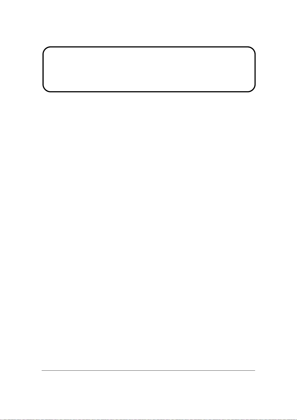
1.4 HANDING AND PLACING METHODS
Correct Methods: Incorrect Methods:
Only touch the metal frame of the LCD
panel or the front cover of the monitor. Do
not touch the surface of the polarizer.
Surface of the LCD panel is pressed by fingers
and that may cause “Mura.”
Take out the monitor with cushions
Taking out the monitor by grasping the LCD
panel. That may cause “Mura.”
ViewSonic Corporation Confidential - Do Not Copy VA712-2_ VA712b-2
2
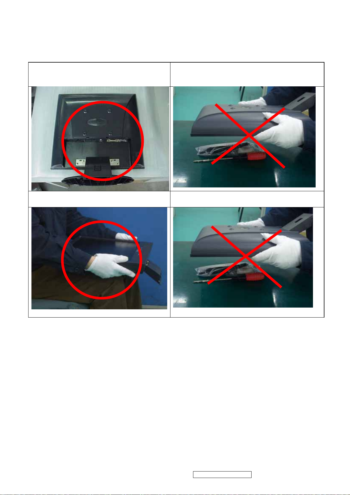
Place the monitor on a clean and soft foam
pad.
Placing the monitor on foreign objects. That
could scratch the surface of the panel or cause
“Mura.”
Place the monitor on the lap, the panel
surface must be upwards.
The panel is placed facedown on the lap. That
may cause “Mura.”
ViewSonic Corporation Confidential - Do Not Copy VA712-2_ VA712b-2
3
2. Specification
2.1 PRODUCT SPECIFICATIONS
LCD Panel 17.0” TFT
Recommend Resolution
1280 x1024@60Hz
Pixel Dimension 0.264(H) x 0.264(V)mm
LCD Display Color 16.2M Colors (RGB 6-bit+FRC data)
Horizontal: 140 °
Viewing Angle
Vertical: 130 °
Contrast Ratio
Brightness
500:1 (Typ.)
300 cd/㎡(Typ.)
Response Time 8ms(Typ.)
Active Display Area 337.9mm(H) x 270.3mm(V)
Maximum Pixel Clock 135 MHz
Horizontal Frequency
Vertical Refresh Rate
30 – 82 kHz
50 – 85 Hz.
Operating: 0°C to +40°C
Temperature
Storage: -20°C to +60°C
Input Signal Analog / Digital
Energy Star compliant VESA
Power Management
DPMS compatible
≦1 W
Input Voltage : 90V~264ACV,50~60Hz(auto switch)
Power
Consumption: 39 Watts(Max.) 36 Watts(Typ.)
ViewSonic Corporation Confidential - Do Not Copy VA712-2_ VA712b-2
4
2.2 FACTORY SUPPORTING MODES
Timing Table :
Item Timing Analog Digital
1 640 x 350 @ 70Hz, 31.5kHz Yes Yes
2 640 x 480 @ 60Hz, 31.5kHz Yes Yes
3 640 x 480 @ 67Hz, 35.0kHz Yes Yes
4 640 x 480 @ 72Hz, 37.9kHz Yes Yes
5 640 x 480 @ 75Hz, 37.5kHz Yes Yes
6 640 x 480 @ 85Hz, 43.27kHz Yes Yes
7 720 x 400 @ 70Hz, 31.5kHz Yes Yes
8 800 x 600 @ 56Hz, 35.1kHz Yes Yes
9 800 x 600 @ 60Hz, 37.9kHz Yes Yes
10 800 x 600 @ 72Hz, 48.1kHz Yes Yes
11 800 x 600 @ 75Hz, 46.9kHz Yes Yes
12 800 x 600 @ 85Hz, 53.7kHz Yes Yes
13 832 x 624 @ 75Hz, 49.7kHz Yes Yes
14 1024 x 768 @ 60Hz, 48.4kHz Yes Yes
15 1024 x 768 @ 70Hz, 56.5kHz Yes Yes
16 1024 x 768 @ 72Hz, 58.1kHz Yes Yes
17 1024 x 768 @ 75Hz, 60.0kHz Yes Yes
18 1024 x 768 @ 85Hz, 68.67kHz Yes Yes
19 1152 x 870 @ 75Hz, 68.6kHz Yes Yes
20 1280 x 1024 @ 60Hz, 63.4kHz Yes Yes
21 1280 x 1024 @ 75Hz, 79.97kHz Yes Yes
22 1280 x 720 @ 60Hz, 45kHz Yes Yes
Primary Preset::VESA : 1280 x1024@60Hz
ViewSonic Corporation Confidential - Do Not Copy VA712-2_ VA712b-2
5
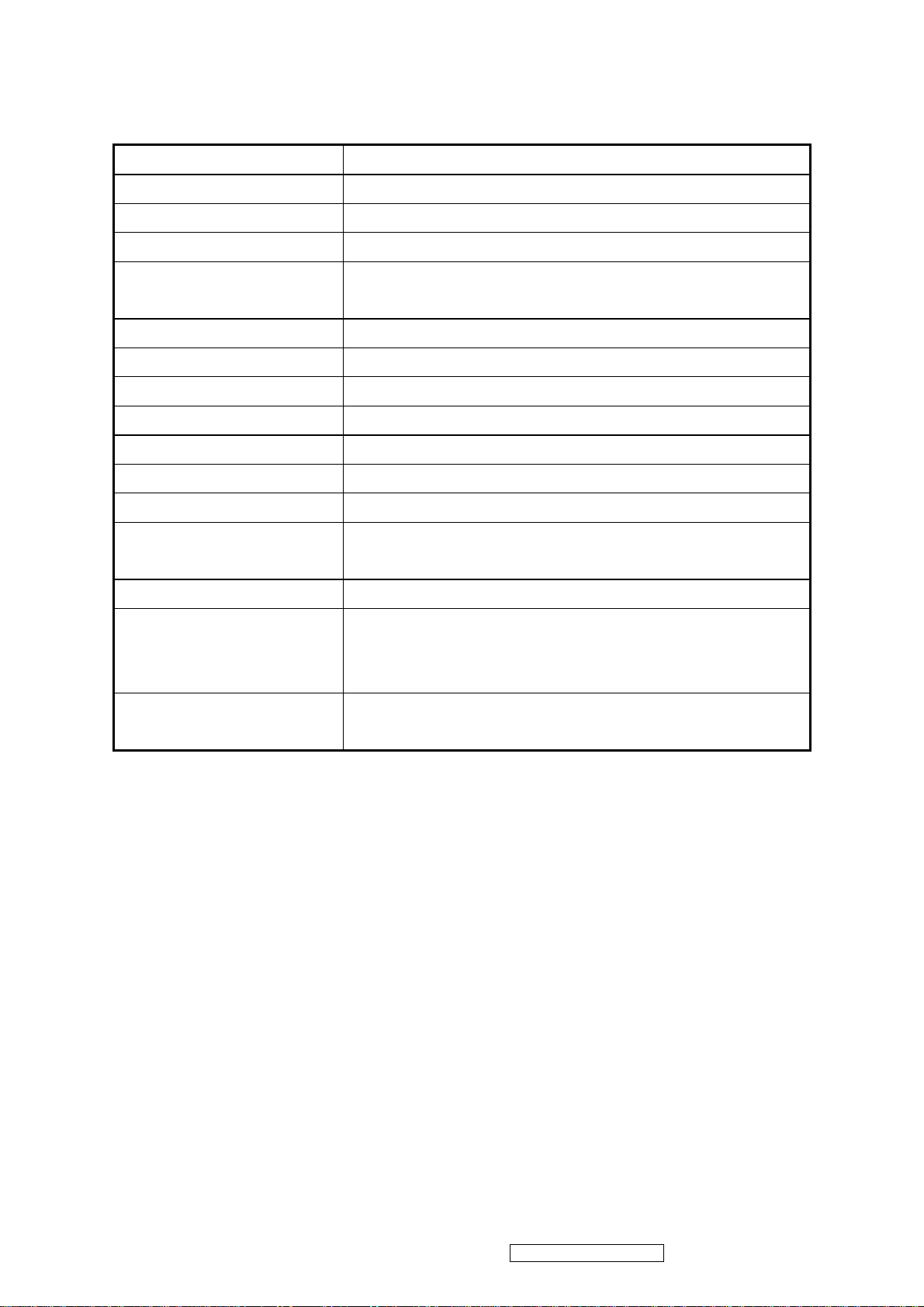
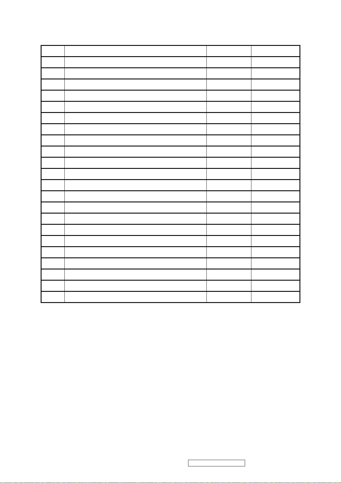
2.3 INTERFACE DESCRIPTION
D-SUB 15 PIN CONNECTOR
15
6
11 15
10
Pin Number Pin Function
1 Red video input
2 Green video input
3 Blue video input
4 No Connection
5 Ground
6 Red video ground
7 Green video ground
8 Blue video ground
9 +5V
10 H/V sync ground
SIGNAL LEVEL
11 No connection
12 (SDA)
Horizontal sync (Composite
13
sync)
14 Vertical sync
15 (SCL)
ViewSonic Corporation Confidential - Do Not Copy VA712-2_ VA712b-2
6

DVI-D 24 PIN CONNECTOR
Pin No. Signal Name Description
1 RX2- TMDS negative differential input, channel 2
2 RX2+ TMDS positive differential input, channel 2
3 GND Logic Ground
4 Reserved 4 Reserved. No connection
5 Reserved 5 Reserved. No connection
6 DDC-CLK DDC2B Clock
7 DDC-DAT DDC2B Data
8 Reserved 8 Reserved. No connection
9 RX1- TMDS negative differential input, channel 1
10 RX1+ TMDS positive differential input, channel 1
11 GND Logic Ground
12 Reserved 12 Reserved. No connection
13 Reserved 13 Reserved. No connection
14 VCCX Power
15 GND Logic Ground
16 SENS SENSE Pin, Pull High
17 RX0- TMDS negative differential input, channel 0
18 RX0+ TMDS positive differential input, channel 0
19 GND Logic Ground
20 Reserved 20 Reserved. No connection
21 Reserved 21 Reserved. No connection
22 GND Logic Ground
23 RXC+ TMDS positive differential input, reference clock
24 RXC- TMDS negative differential input, reference clock
ViewSonic Corporation Confidential - Do Not Copy VA712-2_ VA712b-2
7
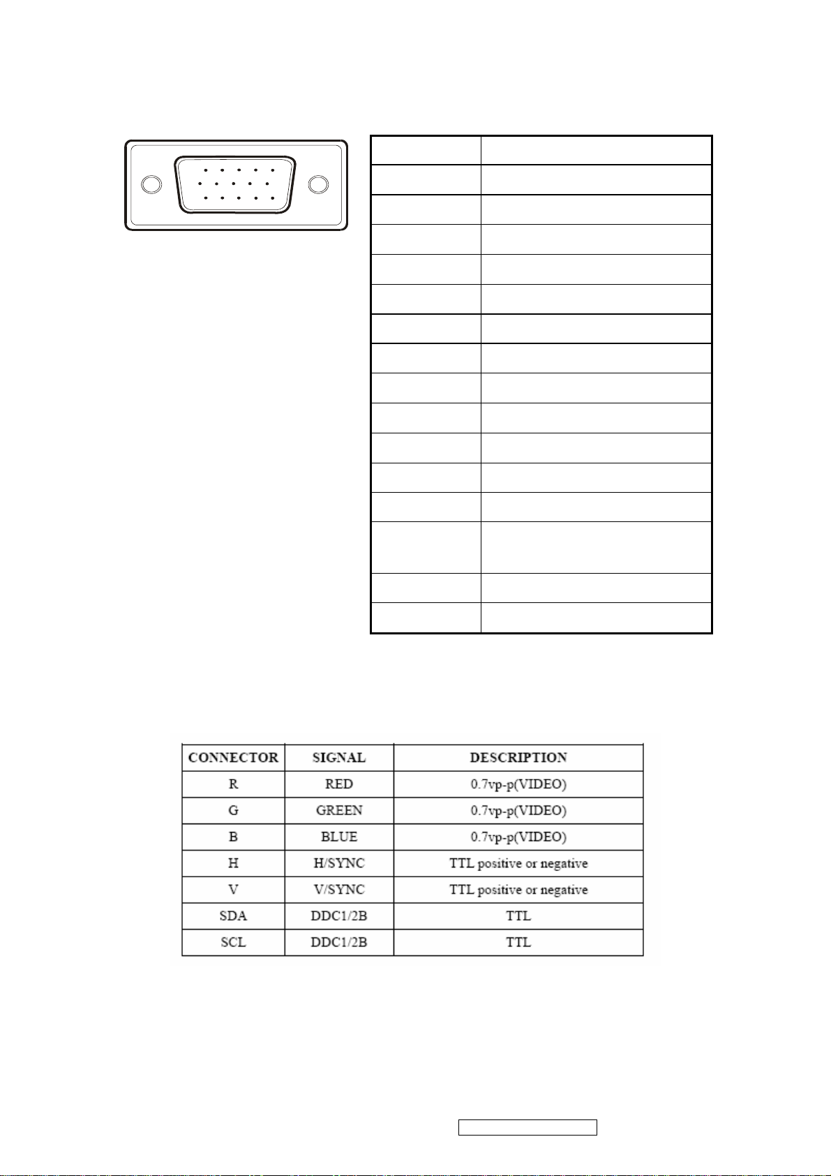
3. Front Panel Function Control Description
ViewSonic Corporation Confidential - Do Not Copy VA712-2_ VA712b-2
8
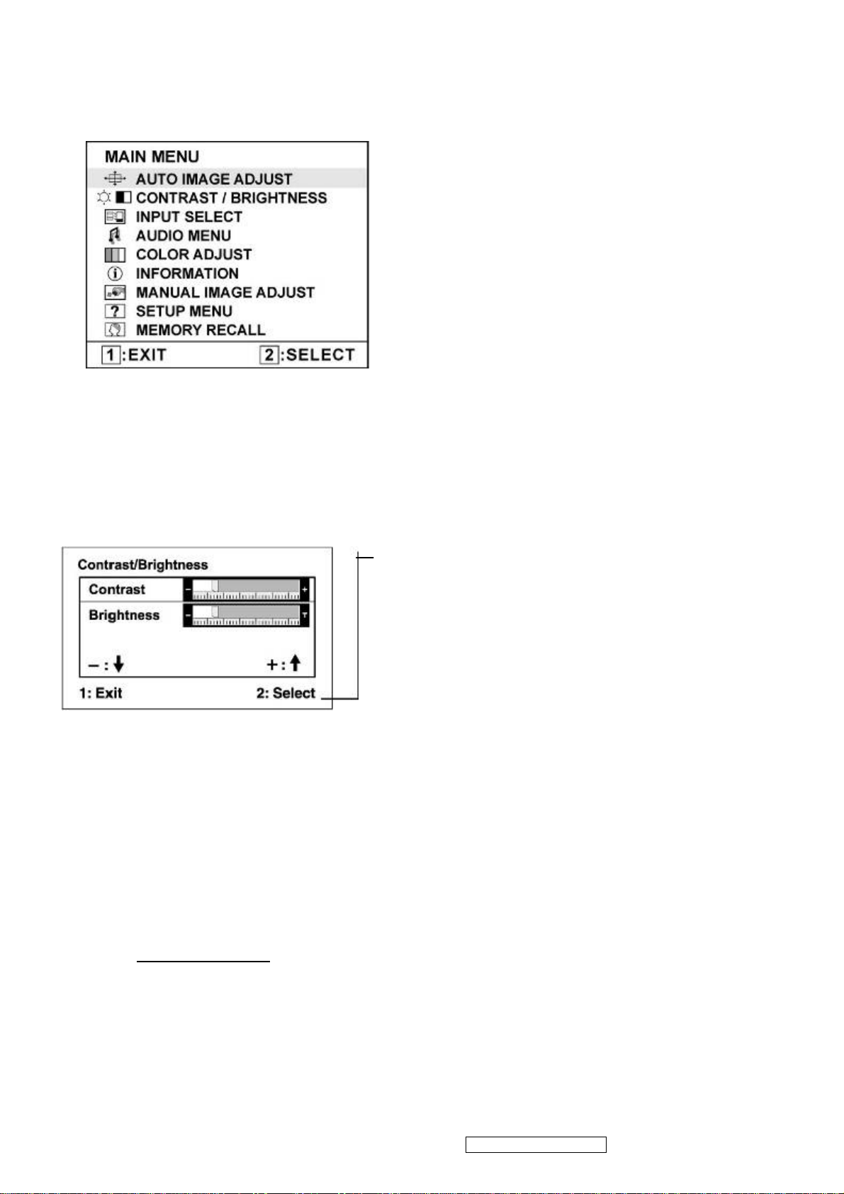
Do the following to adjust the display setting:
1. To display the Main Menu, press button [1].
NOTE: All OSD menus and adjustment screens disappear automatically after about 15 seconds.
This is adjustable through the OSD timeout setting in the setup menu.
2. To select a control to adjust, press or ▼ to ▲ scroll up or down in the Main Menu.
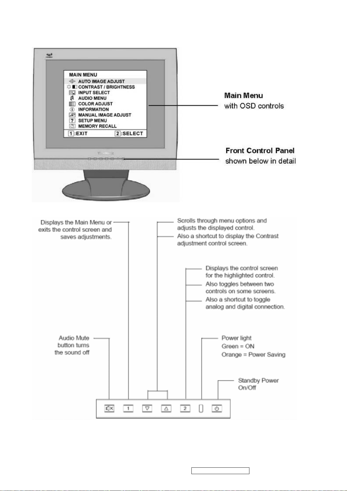
3. After the desired control is selected, press button [2]. A control screen like the one shown
below appears.
The command line at the bottom of the control screen
tells what to do next from this screen. You can toggle
between control screens, adjust the selected option, or
exit the screen.
4. To adjust the setting, press the up ▼ or ▲ down T buttons.
5. To save the adjustments and exit the menu, press button [1] twice.
The following tips may help you optimize your display:
• Adjust the computer's graphics card so that it outputs a 1280 x 1024 @ 60Hz video signal to the
LCD display. (Look for instructions on “changing the refresh rate” in the graphics card's user
guide.)
• If necessary, make small adjustments using H. POSITION and V. POSITION until the screen
image is completely visible. (The black border around the edge of the screen should barely
touch the illuminated “active area” of the LCD display.)
ViewSonic Corporation Confidential - Do Not Copy VA712-2_ VA712b-2
9
Main Menu Controls
Adjust the menu items shown below by using the up and down buttons.
Control Explanation
Auto Image Adjust sizes and centers the screen image automatically.
Contrast adjusts the difference between the image background (black level)
and the foreground (white level).
Brightness adjusts background black level of the screen image.
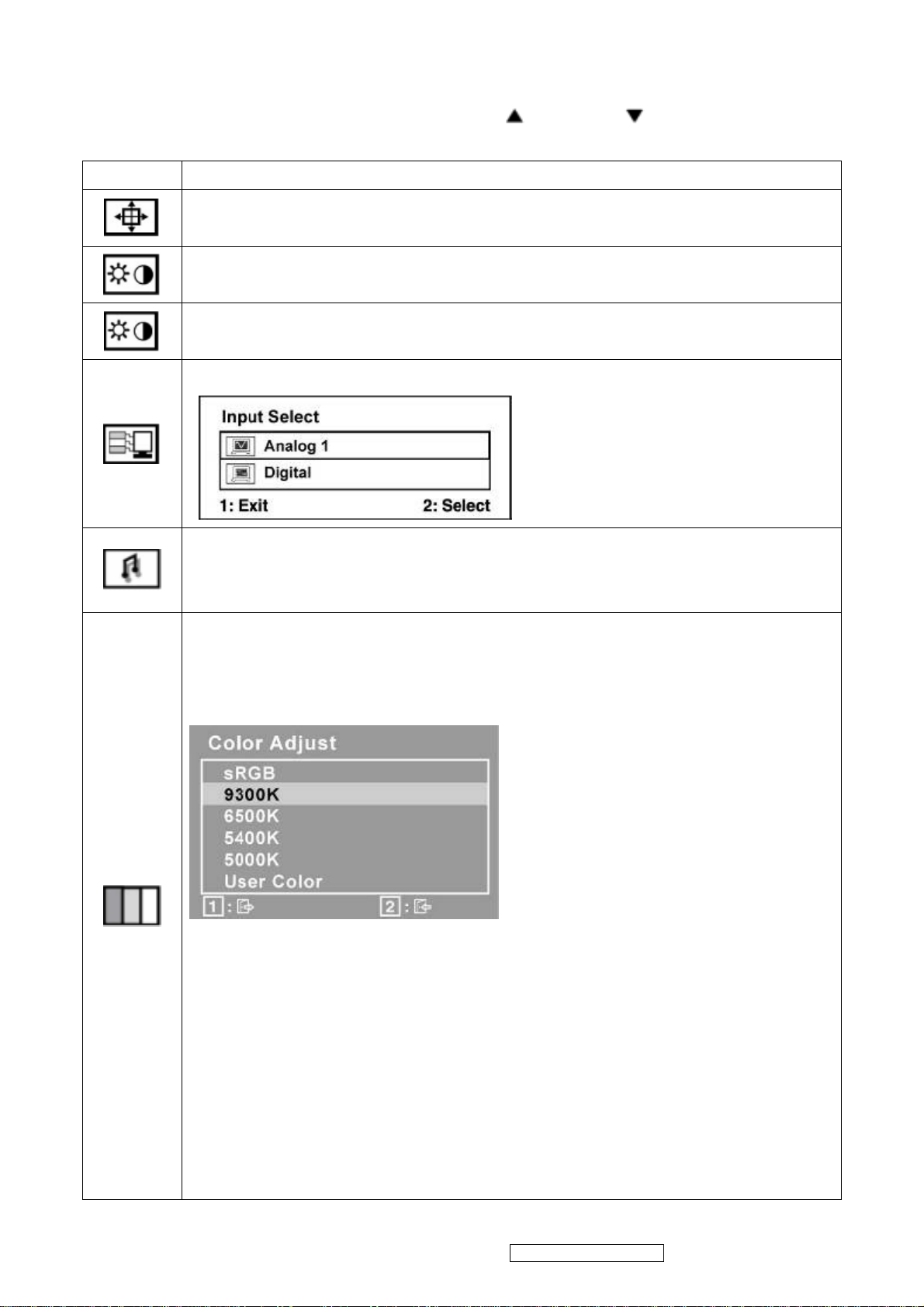
Input Select allows the user to toggle between an analog and a digital signal.
Audio Adjust
Volume increases the volume, decreases the volume, and mutes the audio.
Mute temporarily silences audio output.
Color Adjust provides several color adjustment modes, including preset color
temperatures and a User Color mode which allows independent adjustment of
red (R), green (G), and blue (B). The factory setting for this product is 6500K
(6500 Kelvin).
9300K-Adds blue to the screen image for cooler white (used in most office
settings with fluorescent lighting).
6500K-Adds red to the screen image for warmer white and richer red.
5400K-Adds green to the screen image for a darker color.
5000K-Adds blue and green to the screen image for a darker color.
User Color Individual adjustments for red (R), green (G), and blue (B).
1. To select color (R, G or B) press button [2].
2. To adjust selected color, press ▼ and ▲.
Important: If you select RECALL from the Main Menu when the product is
set to a Preset Timing Mode, colors return to the 6500K factory preset.
ViewSonic Corporation Confidential - Do Not Copy VA712-2_ VA712b-2
10
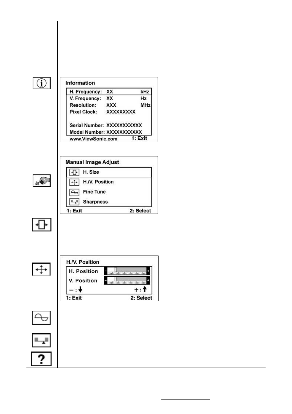
Information displays the timing mode (video signal input) coming from the
graphics card in the computer, the LCD model number, the serial number, and
the ViewSonic® website URL. See your graphics card’s user guide for
instructions on changing the resolution and refresh rate (vertical frequency).
NOTE: VESA 1280 x 1024 @ 60Hz (recommended) means that the resolution
is 1280 x 1024 and the refresh rate is 60 Hertz.
Manual Image Adjust Sub-menu
H. Size (Horizontal Size) adjusts the width of the screen image.
H./V. Position (Horizontal/Vertical Position) moves the screen image left or
right and up or down.
Fine Tune sharpens the focus by aligning text and/or graphics with pixel
boundaries.
NOTE: Try Auto Image Adjust first.
Sharpness adjusts the clarity and focus of the screen image.
Setup Menu displays the menu shown below:
ViewSonic Corporation Confidential - Do Not Copy VA712-2_ VA712b-2
11
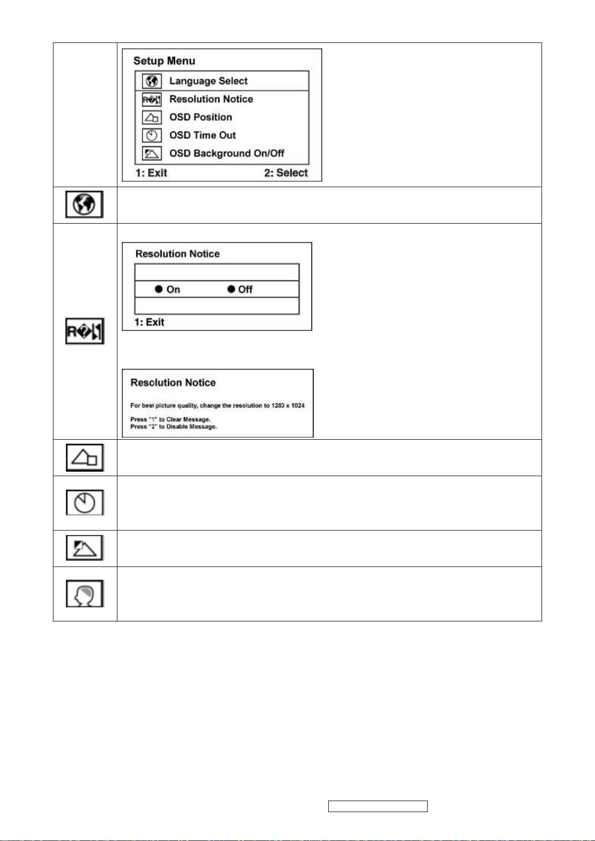
Language Select allows the user to choose the language used in the menus
and control screens.
Resolution Notice allows the user to enable or disable this notice.
If you enable the Resolution Notice shown above and your computer is set at a
resolution other than 1280 x 1024, the following screen appears.
OSD Position allows the user to move the OSD menus and control screens.
OSD Timeout sets the length of time the OSD screen is displayed. For
example, with a “30 second” setting, if a control is not pushed within 30
seconds, the display screen disappears.
OSD Background allows the user to turn the OSD background On or Off.
Memory Recall returns the adjustments back to factory settings if the display
is operating in a factory Preset Timing Mode listed in the Specifications of this
manual.
ViewSonic Corporation Confidential - Do Not Copy VA712-2_ VA712b-2
12
SHORT CUTS FUNCTION FROM THE BUTTONS
[1] Main Menu
[2] Auto Image Adjust
[▼] or [▲]
To immediately activate Contrast menu. It should be
change to Brightness OSD by push button [2]
Recall Contrast or Brightness while in the Contrast or
[▼] + [▲]
Brightness adjustment, or recall both of Contrast and
Brightness when the OSD is not open.
Toggle 720x400 and 640x400 mode when input 720x400
[1] + [2]
or 640x400 mode
[1] + [▼] + [▲] White Balance (Not shown on user’s guide)
• Power Lock: Press and hold “[2], & ▼” for 10 seconds. If
the power button is pressed the message Power Button
Locked will display for 5 seconds. With or without this
[1] + [▼]
setting, after a power failure, your LCD display’s power
will automatically turn ON when power is restored.
• Power Unlock: Press and hold “[2], & ▼” again for 10
seconds.
• OSD Lock: Press and hold "[1], & (▲)" for 10 seconds. If
any buttons are pressed the message OSD Locked will
[1] + [▲]
display for 5 seconds.
• OSD Unlock: Press and hold “[1], & ▲” again for 10
seconds.
[;U] Volume mute on/off
Remark : All the short cuts function are only available while OSD off
ViewSonic Corporation Confidential - Do Not Copy VA712-2_ VA712b-2
13
4. Circuit Description
4.1 LCD MONITOR DESCRIPTION
The LCD MONITOR will contain a Main Board, an Power Board, Key Board which house the flat
panel control logic, brightness control logic and DDC.
The Power Board will provide AC to DC Inverter voltage to drive the backlight of panel and the
Main Board chips each voltage.
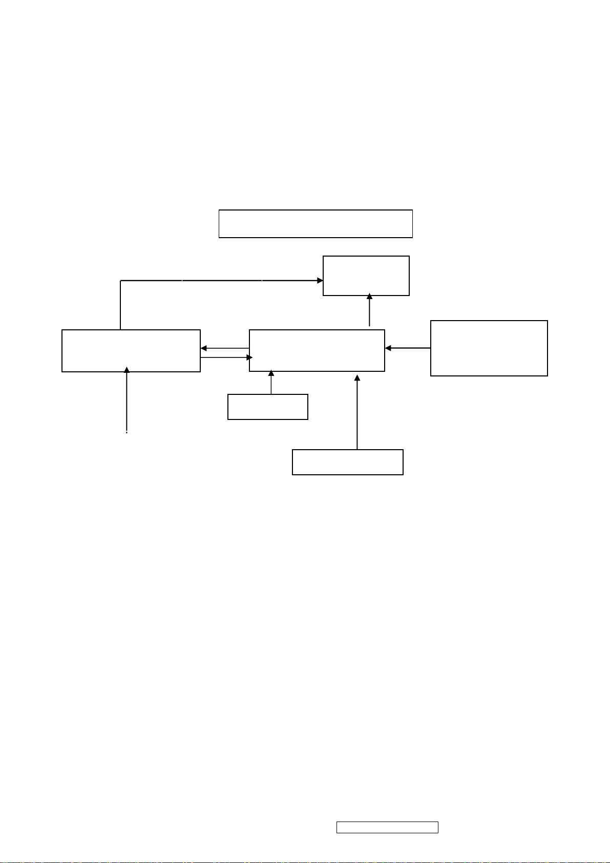
Monitor Block Diagram
Power Board
(Include: adapter, inverter)
AC-IN
100V-240V
CCFL Drive.
Key Board
Flat Panel and
CCFL backlight
Main Board
HOST Computer
RS232 Connector
For white balance
adjustment in factory
mode
Video signal, DDC
ViewSonic Corporation Confidential - Do Not Copy VA712-2_ VA712b-2
14
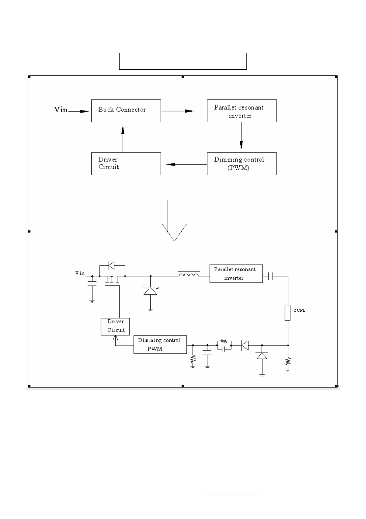
4.2 POWER BLOCK FUNCTION DESCRIPTION
Inverter Block Function
ViewSonic Corporation Confidential - Do Not Copy VA712-2_ VA712b-2
15
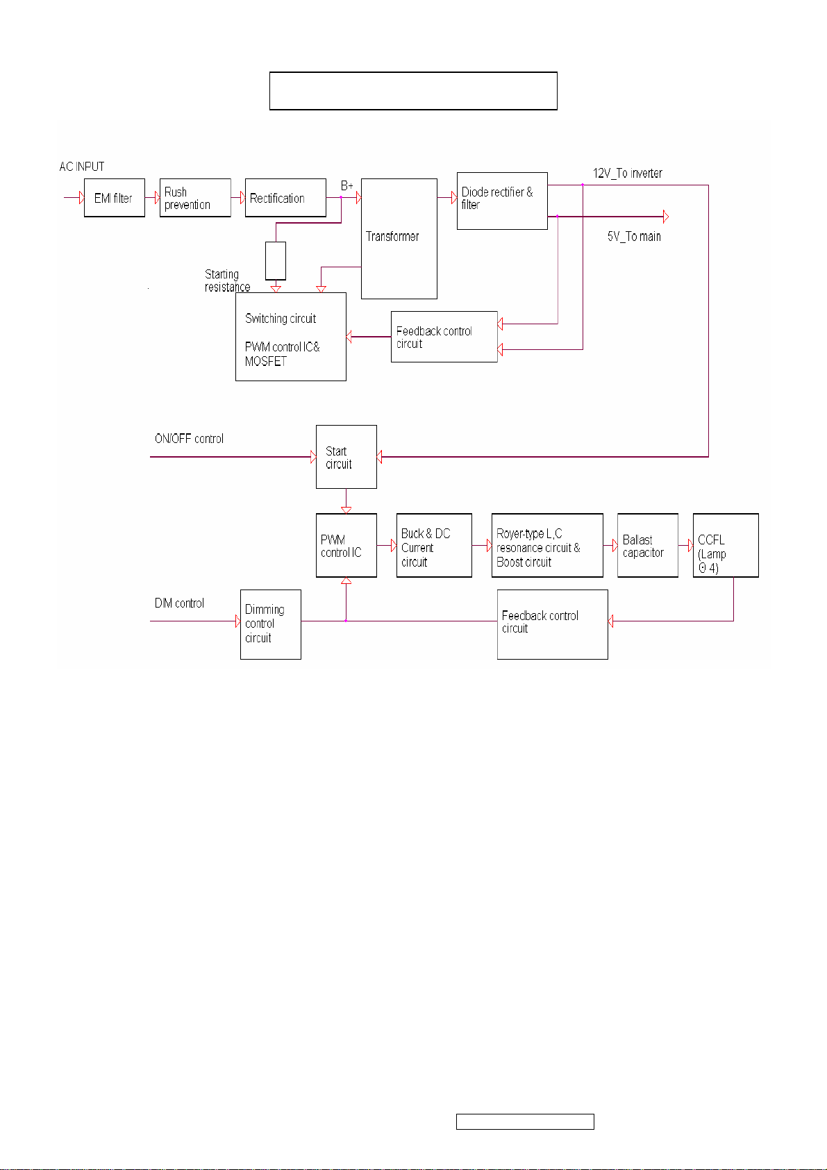
Power Block Function
4.3 Function Test and Alignment Procedure
All Modes Reset
You should do “All Mode Reset” (Refer to Chapter III-3. Hot Keys for Function
Controls) first. This action will allow you to erase all end-user’s settings and restore
the factory defaults.
Auto Image Adjust
Please select and enter “Auto Image Adjust” function on Main Menu to see if it is
workable. The “Auto Image Adjust” function is aimed to offer a better screen quality
by built-in ASIC. For optimum screen quality, the user has to adjust each function
manually.
Firmware
Test Pattern: Burn In Mode (Refer to Chapter III-3. Hot Keys for Function Controls)
- Make sure the F/W is the latest version.
DDC
Test Pattern: EDID program
ViewSonic Corporation Confidential - Do Not Copy VA712-2_ VA712b-2
16

Make sure it can pass test program.
Fine Tune and Sharpness
Test Signal: 1280*1024@60Hz
Test Pattern: Line Moire Pattern
Check and see if the image has noise and focus performs well. Eliminate visual
line bar.
If not, readjust by the following steps:
(a)Select and enter “Fine Tune” function on “Manual Image Adjust” to adjust the
image to eliminate visual wavy noise.
(b)Then, select and enter “Sharpness” function to adjust the clarity and focus of
the screen image.
Boundary
Test Signal: 1280*1024@60Hz
Test Pattern: Horizontal & Vertical Line Thickness Pattern
Check and see if the image boundary is within the screen frame.
If not, readjust by the following steps:
(a)Select and enter “Manual Image Adjust” function on OSD Main Menu.
(b)Then, select and enter “Horizontal Size” or “Horizontal/Vertical Position” function
to adjust the video boundary to be full scanned and within screen frame.
White Balance
Test Signal: 640*480@60Hz
Test Pattern: White and Black Pattern
1.5.8 R, G, B, Colors Contrast
Test Signal: 1280*1024@60Hz
Test Pattern: R, G, B, Color Intensities Pattern and 16 Gray Scale Pattern
- Check and see if each color is normal and distinguishable.
- If not, please return the unit to repair area.
Screen Uniformity and Flicker
Test Signal: 1280*1024@60Hz
Test Pattern: Full White Pattern
- Check and see if it is in normal condition.
1.5.10 Dead Pixel and Line
Test Signal: 1280*1024@60Hz
Test Pattern: Dark and White Screen Pattern
- Check and see if there are dead pixels on LCD panel with shadow gauge and
filter film.
- The total numbers and distance of dead pixels should be compliant with the
spec.
Mura
Test Pattern: White, RGB, Black, & Grey
Test Tool: 10% ND Filter
- Check if the Mura can pass 10% ND Filter.
Audio
Test Signal: Voice signal (optional, depend on model)
Test Pattern: liberty
- Make sure there is audio output.
- Make sure that audio function (volume 80%) is working without noise and
ViewSonic Corporation Confidential - Do Not Copy VA712-2_ VA712b-2
17

resonance.
- Make sure that the sound of right and left speakers are in balance.
Check for Secondary Display Modes
Test Signal:
Analog: 640*350@70Hz; 640*480@60/67/72/75/85Hz;
720*400@70Hz; 800*600@56/60/72/75/85Hz;
832*624@75Hz, 1024*768@60/70/72/75/85Hz;
1280*1024@60/75Hz
Digital: 640*350@70Hz; 640*480@60/72/75/85Hz;
720*400@70Hz; 800*600@56/60/72/75/85Hz;
1024*768@60/70/72/75/85Hz; 1152*870@75Hz,
1280*720@60Hz, 1280*1024@60Hz
- Normally when the primary mode 1280*1024@60Hz is well adjusted and
compliant with the specification, the secondary display modes will also be
compliant with the spec. But we still have to check with the general test pattern to
make sure every secondary is compliant with the specification.
-
All Modes Reset
After final QC step, we have to erase all saved changes again and restore the
factory defaults. You should do “All Mode Reset” again.
Power Off Monitor
Turn off the monitor by pressing “Power” button.
ViewSonic Corporation Confidential - Do Not Copy VA712-2_ VA712b-2
18
4.4 INTRODUCTION OF IC
RTD2523B-LF(U401): integrate ADC, OSD, TMPS, RSDS TX, LVDS TX, convert
analog RGB into digital and room and shrink scaling output to LCD panel.
PIN Function:
Pin Symbol Description
127 XO Crystal OSC output
128 XI Reference clock input from external crystal or from
single-ended CMOS/TTL OSC(3.3V tolerance)
50
51
121
120
DDCSCL1(ADC) Open drain(Internal 75K pull high)
DDCSDA1(ADC) Open drain(Internal 75K pull high)
DDCSCL2(DVI) Open drain(Internal 75K pull high)
DDCSDA2(DVI) Open drain(Internal 75K pull high)
123 RESET_OUT Reset out Open drain( internal 75KOhm high)
110/48 COUT Crystal out
124 33VRST_REF Reference 3.3V for Reset Out
109 33VPNLOUT
Panel on/off switch out (Max current driving 1A)
58 BJT_B Embedded regulator P type BJT control pin out
5 TMDS_TST TMDS_TEST Pin;
Power-on-latch for host interface type.
7/13 TMDS_VDD
TMDS power(3.3V)
6 REXT Impedance Match Reference.
49/112 PWM2
4/48/111 PWM1
3/5/122 PWM0
4 BYPASS For External Bypass Capacitor
125 DPLL_VDD
2 APLL_VDD
Power for digital PLL(3.3V)
Power for multi-phase PLL(3.3V)
3 PLL_TEST1 Test Pin 1;Power-on-latch for MCU crystal location
4 PLL_TEST2 Test Pin 2;Power-on-latch for crystal in frequency
56/118 SCSB
57/119 SCLK
Serial control I/F chip select(Open drain)
Serial control I/F clock(Open drain)
59/83/108 Pad 3.3V Power PVCC
47/116 Digital 1.8V Power VCCK
21/38 ADC_VDD
ADC Power(1.8V)
40 VCLK Video8 Clock
19 AVSO ADC vertical sync input
5V tolerance
Power from PIN 13
20 AHSO ADC horizontal sync input
Adjustable Schmidt trigger 5V tolerance
Power from PIN 13
AIC1084-33PM (U701): DC power convert, used to 5v convert 3.3v.
ViewSonic Corporation Confidential - Do Not Copy VA712-2_ VA712b-2
19
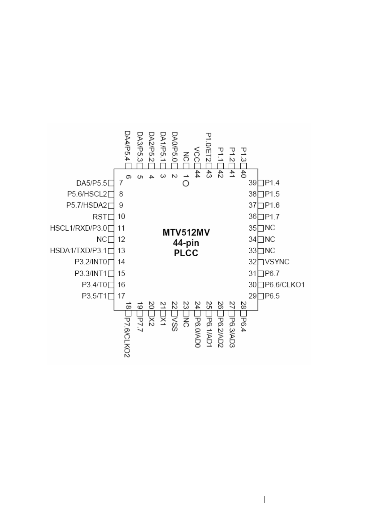
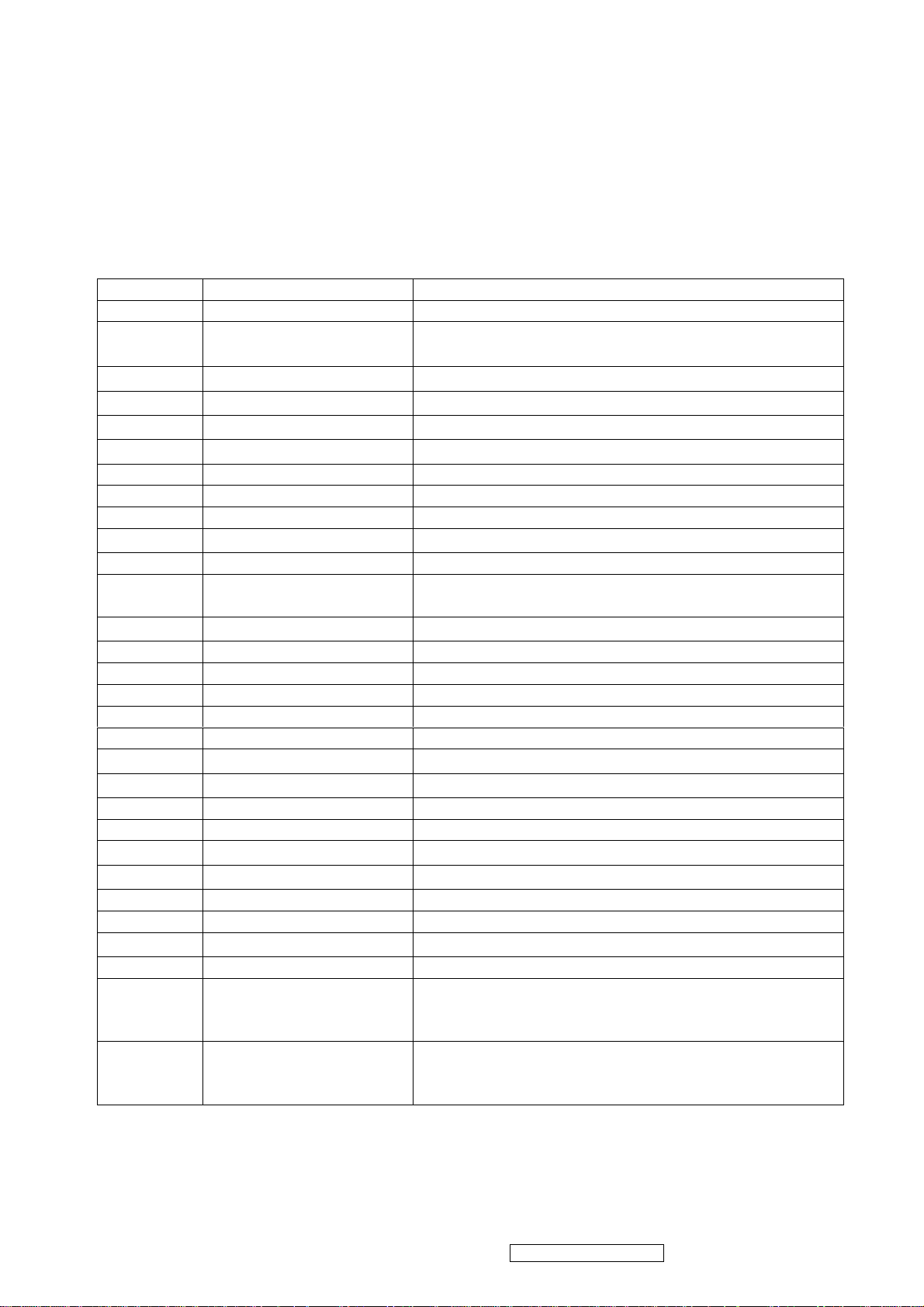
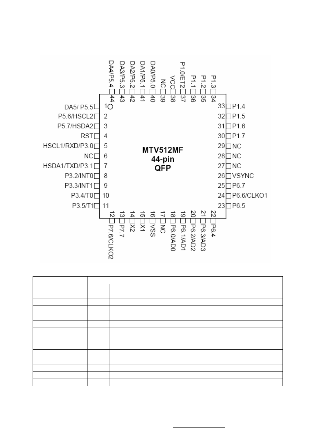
MTV512GMV64 (U402): The MTV512M micro-controller is an 8051 CPU core
embedded device especially tailored for flat panel display applications. It
includes an 8051 CPU core, 768-byte SRAM, 4 channels of 6-bit ADC, 3
external counters/timers, 6 channels of PWM DAC, VESA DDC interface,
and a 64K-byte internal program Flash-ROM memory.
Circuit Diagram
ViewSonic Corporation Confidential - Do Not Copy VA712-2_ VA712b-2
20
PIN Function
Name
NC 1 39
DA0/P5.0 2 40
DA1/P5.1 3 41
DA2/P5.2 4 42
DA3/P5.3 5 43
DA4/P5.4 6 44
DA5/P5.5 7 1
P5.6/HSCL2 8 2
P5.7/HSDA2 9 3
RST 10 4
HSCL1/P3.0/RXD 11 5
HSDA1/P3.1/RXD 13 7
P3.2/INT0 14 8
ViewSonic Corporation Confidential - Do Not Copy VA712-2_ VA712b-2
Pin No.
PLCC QFP
DESCRIPTION
No connection
PWM DAC output/General purpose I/O (open drain)
PWM DAC output/General purpose I/O (open drain)
PWM DAC output/General purpose I/O (open drain)
PWM DAC output/General purpose I/O (open drain)
PWM DAC output/General purpose I/O (open drain)
PWM DAC output/General purpose I/O (open drain)
General purpose I/O/Slave llC1 SCL2(open drain)
General purpose Output/Slave llC1 SCL2(open drain)
High Active RESET
Slave IIC clock/General purpose I/O/Rxd (open drain)
Slave IIC clock/General purpose I/O/Txd (open drain)
General purpose I/O/External interrupt 0(Standard 8051)
21
 Loading...