

Page 1

Service Manual
ViewSonic VA703b-1
VA703m-1
Model No. VS11280
17” Color TFT LCD Display
(VA703b-1_VA703m-1_SM Rev. 1b Oct. 2006)
ViewSonic 381 Brea Canyon Road, Walnut, California 91789 USA - (800) 888-8583
Page 2
Copyright
Copyright © 2006 by ViewSonic Corporation. All rights reserved. No part of this publication
may be reproduced, transmitted, transcribed, stored in a retrieval system, or translated into any
language or computer language, in any form or by any means, electronic, mechanical, magnetic,
optical, chemical, manual or otherwise, without the prior written permission of ViewSonic
Corporation.
Disclaimer
ViewSonic makes no representations or warranties, either expressed or implied, with respect to
the contents hereof and specifically disclaims any warranty of merchantability or fitness for any
particular purpose. Further, ViewSonic reserves the right to revise this publication and to make
changes from time to time in the contents hereof without obligation of ViewSonic to notify any
person of such revision or changes.
Trademarks
Optiquest is a registered trademark of ViewSonic Corporation.
ViewSonic is a registered trademark of ViewSonic Corporation.
All other trademarks used within this document are the property of their respective owners.
Revision History
Revision SM Editing Date ECR Number Description of Changes Editor
1a 7/28/2006 Initial Release Jamie C.
1b 10/24/2006 VS-E060297 Add 2nd panel source (CPT) Jamie C.
ViewSonic Corporation Confidential - Do Not Copy VA703b-1_VA703m-1
i
Page 3
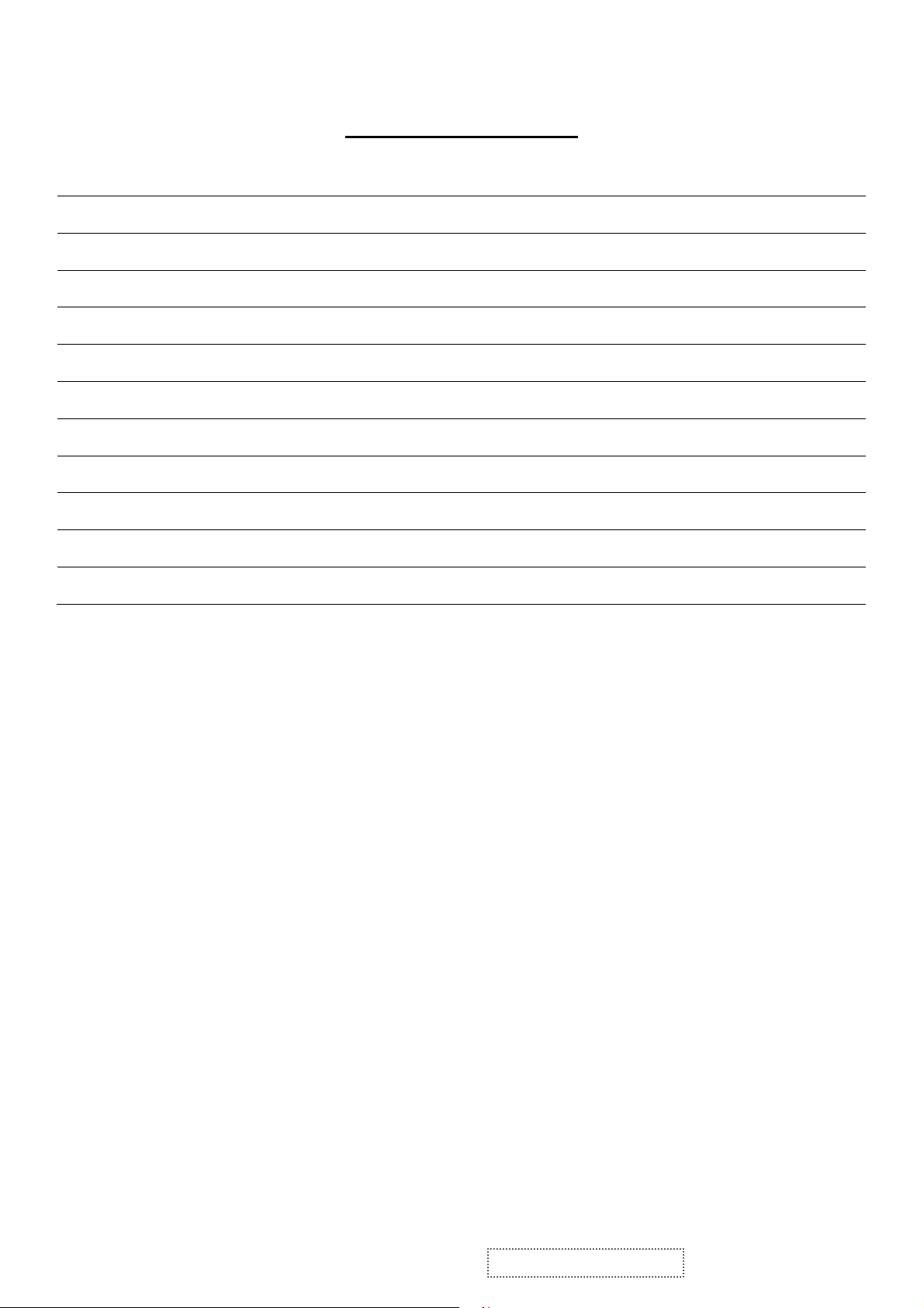
TABLE OF CONTENTS
1. Precautions and Safety Notices 1
2. Specification 4
3. Front Panel Function Control Description 6
4. Circuit Description 12
5. Adjustment Procedure 20
6. Troubleshooting Flow Chart 44
7. Recommended Spare Parts List 45
8. Exploded Diagram and Exploded Parts List 49
9. Block Diagram 53
10. Schematic Diagrams 54
11. PCB Layout Diagrams 63
ViewSonic Corporation Confidential - Do Not Copy VA703b-1_VA703m-1
ii
Page 4

1. Precautions and Safety Notices
1.1 SAFETY PRECAUTIONS
This monitor is manufactured and tested on a ground principle that a user’s safety comes
first. However, improper use or installation may cause damage to the monitor as well as
the user. Carefully go over the following WARNINGS before installing and keep this guide
handy.
WARNINGS
.This monitor should be operated only at the correct power sources indicated on the label
on the rear end of the monitor. If you’re unsure of the power supply in your residence,
consult you local dealer or power company.
.Use only the special power adapter that comes with this monitor for power input.
.Do not try to repair the monitor your self as it contains no user-serviceable parts. This
monitor should only be repaired by a qualified technician.
.Do not remove the monitor cabinet. There is high-voltage parts inside that may cause
electric shock to human bodies, even when the power cord is unplugged.
.Stop using the monitor if the cabinet is damaged. Have it checked by a service technician.
.Put your monitor only in a clean, dry environment. If it gets wet, unplug the power cable
immediately and consult your service technician.
.Always unplug the monitor before cleaning it .Clean the cabinet with a clean, dry cloth.
Apply non-ammonia based cleaner onto the cloth, not directly onto the glass screen.
.Keep the monitor away from magnetic objects, motors, TV sets, and transformer.
.Do not place heavy objects on the monitor or power cord.
1.2 PRODUCT SAFETY NOTICE
Many electrical and mechanical parts in this chassis have special safety visual inspections
and the protection afforded by them cannot necessarily be obtained by using replacement
components rated for higher voltages, wattage, etc. Before replacing any of these
components read the parts list in this manual carefully. The use of substitute replacement
parts which do not have the same safety characteristics as specified in the parts list may
create shock, fire ,or other hazards.
1.3 SERVICE NOTES
1. When replacing parts or circuit boards, clamp the lead wires around terminals before
soldering.
2. When replacing a high wattage resistor(more than 1W of metal oxide film resistor) in
circuit board, keep the resistor about 5mm away from circuit board.
3. Keep wires away from high voltage, high temperature components and sharp edges.
4. Keep wires in their original position so as to reduce interference.
5. Usage of this product please refer to also user’s manual.
ViewSonic Corporation Confidential - Do Not Copy VA703b-1_VA703m-1
1
Page 5
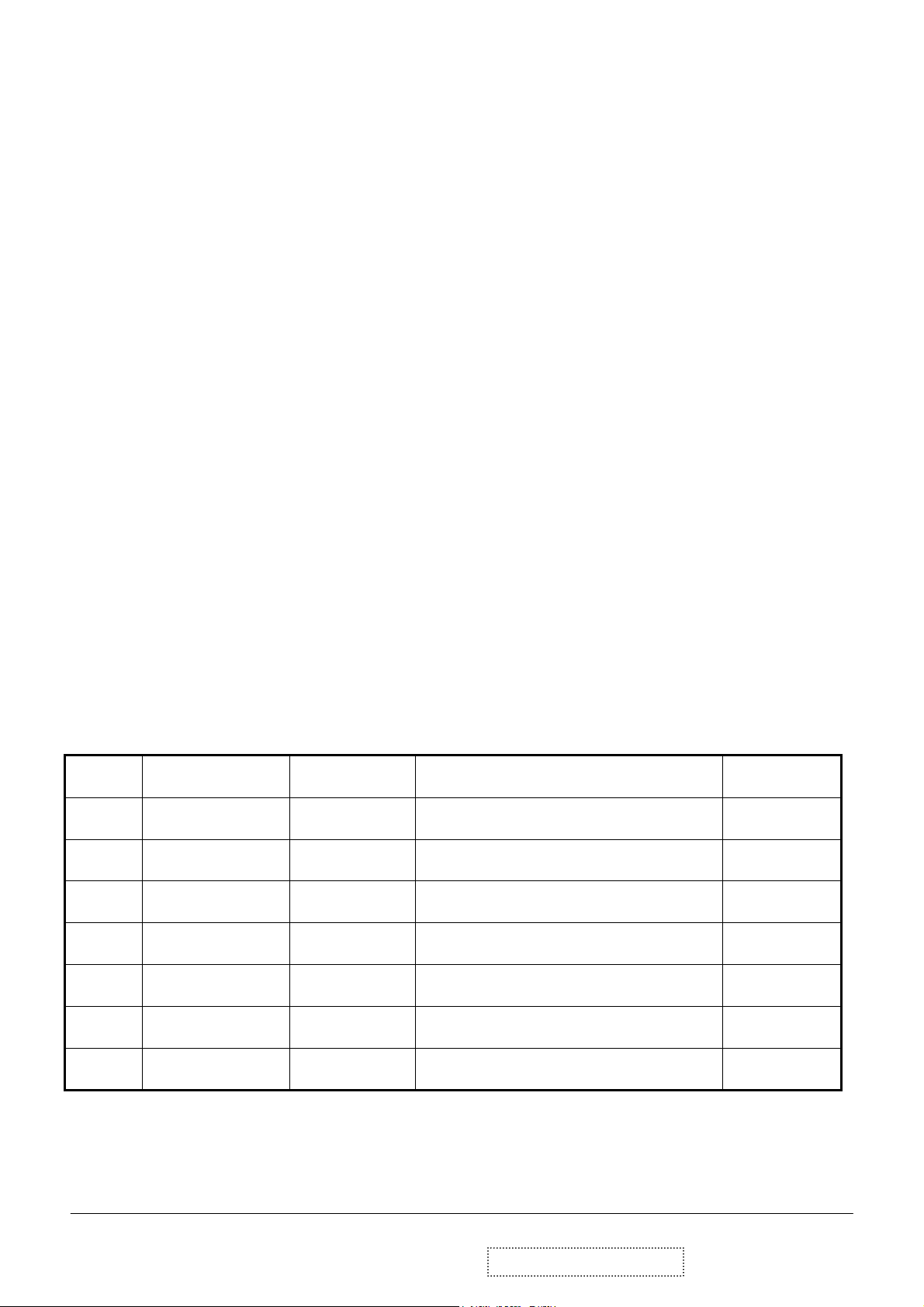
1.4 HANDING AND PLACING METHODS
Correct Methods: Incorrect Methods:
Only touch the metal frame of the LCD
panel or the front cover of the monitor. Do
not touch the surface of the polarizer.
Surface of the LCD panel is pressed by fingers
and that may cause “Mura.”
Take out the monitor with cushions
Taking out the monitor by grasping the LCD
panel. That may cause “Mura.”
ViewSonic Corporation Confidential - Do Not Copy VA703b-1_VA703m-1
2
Page 6
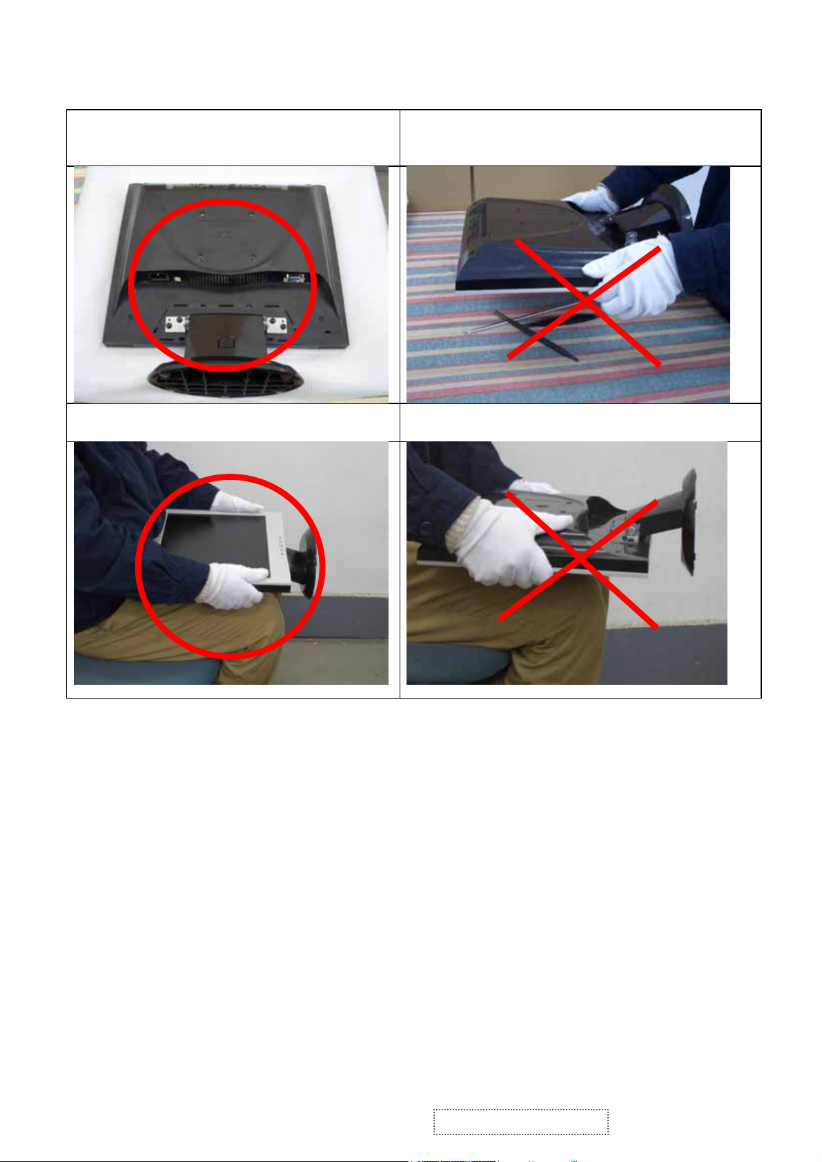
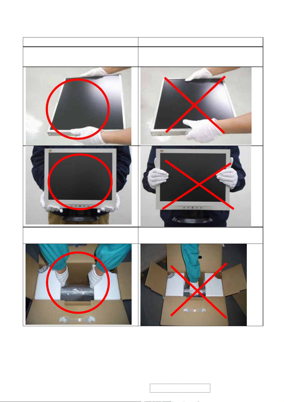
Place the monitor on a clean and soft foam
pad.
Place the monitor on the lap, the panel
surface must be upwards.
Placing the monitor on foreign objects. That
could scratch the surface of the panel or cause
“Mura.”
The panel is placed facedown on the lap. That
may cause “Mura.”
ViewSonic Corporation Confidential - Do Not Copy VA703b-1_VA703m-1
3
Page 7
2. Specification
2.1 PRODUCT SPECIFICATIONS
LCD Panel 17.0” TFT
Recommend Resolution 1280 x 1024@60Hz
Pixel Dimension 0.264(H) x 0.264(V)mm
LCD Display Color 16.2M Colors (6+2bit panel)
Viewing Angle
Contrast Ratio 700:1 (Typ.)
Brightness 300 cd/㎡(Typ.)
Response Time 8ms(Typ.)
Active Display Area 337.92mm(H) x 270.336mm(V)
Maximum Pixel Clock 135 MHz
Horizontal Frequency 30 – 82 kHz
Vertical Refresh Rate 50 – 85 Hz.
Temperature
Power Management
Horizontal: 150
Vertical: 135 °
Operating: 0°C to +40°C
Storage: -20°C to +60°C
Energy Star compliant VESA
DPMS compatible
<1 W
°
Input Voltage : 100V~240V
Power
Consumption: ON Mode < 35 W (max)
POWER SAVING < 2W
OFF < 1W
4
ViewSonic Corporation Confidential - Do Not Copy VA703b-1_VA703m-1
Page 8
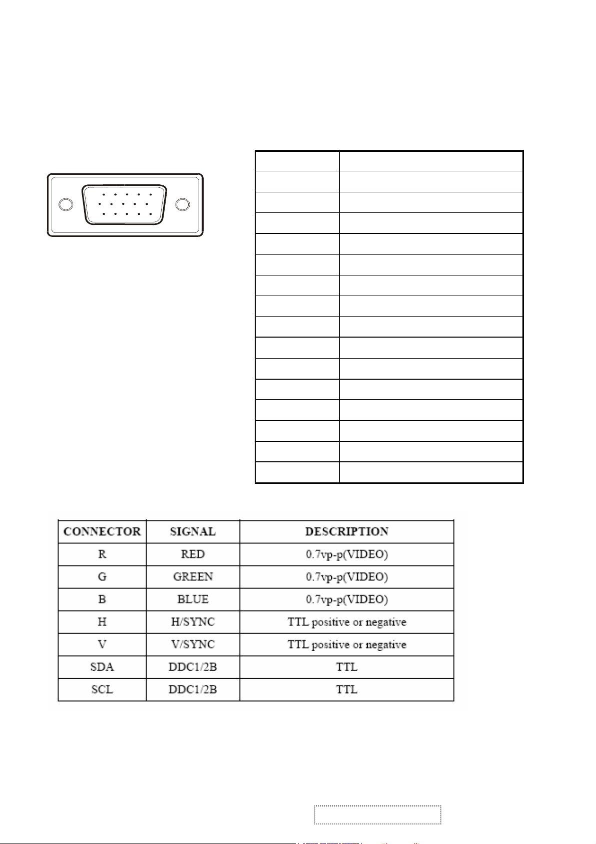
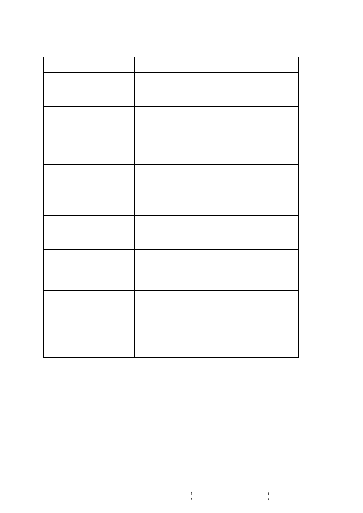
2.2 INTERFACE DESCRIPTION
D-SUB 15 PIN CONNECTOR
15
6
11 15
10
SIGNAL LEVEL
Pin Number Pin Function
1 Red video input
2 Green video input
3 Blue video input
4 No Connection
5 Ground
6 Red video ground
7 Green video ground
8 Blue video ground
9 +5V
10 H/V sync ground
11 No connection
12 (SDA)
13 Horizontal sync (Composite sync)
14 Vertical sync
15 (SCL)
ViewSonic Corporation Confidential - Do Not Copy VA703b-1_VA703m-1
5
Page 9
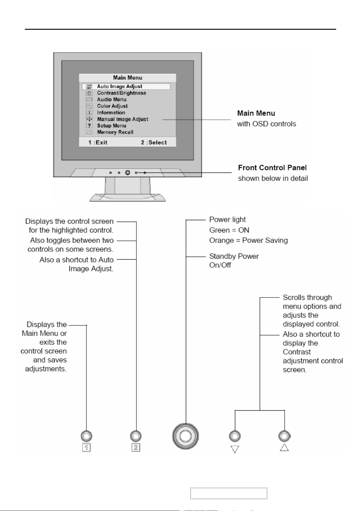
3. Front Panel Function Control Description
ViewSonic Corporation Confidential - Do Not Copy VA703b-1_VA703m-1
6
Page 10
Do the following to adjust the display setting:
1. To display the Main Menu, press button [1].
NOTE: All OSD menus and adjustment screens disappear automatically after about 15
seconds. This is adjustable through the OSD timeout setting in the setup menu.
2. To select a control to adjust, press ▲or ▼ to scroll up or down in the Main Menu.
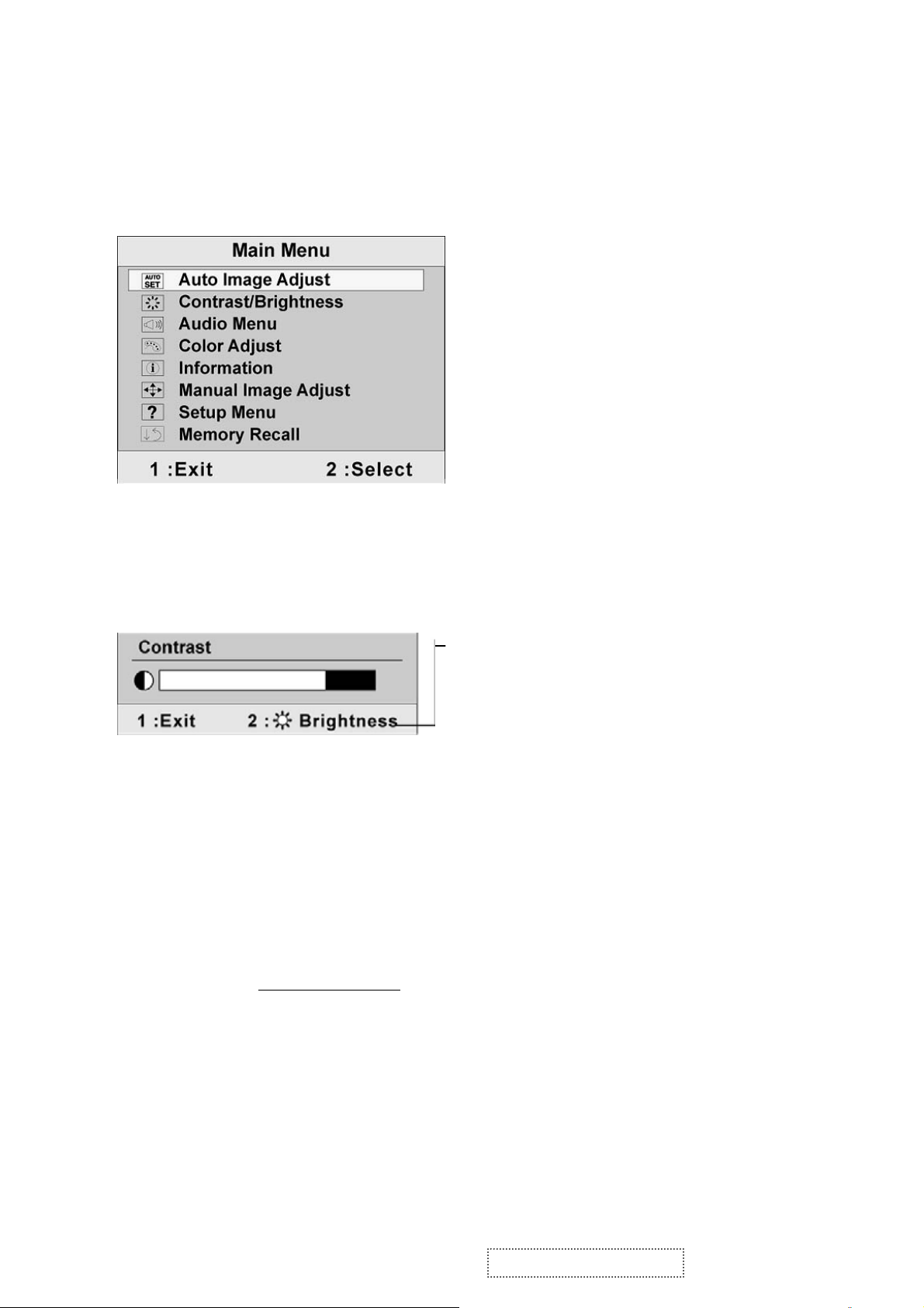
3. After the desired control is selected, press button [2]. A control screen like the one
shown below appears.
The line at the bottom of the screen shows the
current functions of buttons 1 and 2: Exit or
select the Brightness control.
4. To adjust the control, press the up ▲ or▼ down T buttons.
5. To save the adjustments and exit the menu, press button [1] twice.
The following tips may help you optimize your display:
• Adjust the computer's graphics card so that it outputs a 1024 x 768 @ 60Hz video
signal to the LCD display. (Look for instructions on “changing the refresh rate” in the
graphics card's user guide.)
• If necessary, make small adjustments using H. POSITION and V. POSITION until the
screen image is completely visible
should barely touch the illuminated “active area” of the LCD display.)
. (The black border around the edge of the screen
ViewSonic Corporation Confidential - Do Not Copy VA703b-1_VA703m-1
7
Page 11
Main Menu Controls
Adjust the menu items shown below by using the up S and down T buttons.
Control Explanation
Auto Image Adjust automatically sizes, centers, and fine tunes the video signal
to eliminate waviness and distortion. Press the [2] button to obtain a sharper
image.
NOTE: Auto Image Adjust works with most common video cards. If this
function does not work on your LCD display, then lower the video refresh rate
to 60 Hz and set the resolution to its pre-set value.
Contrast adjusts the difference between the image background (black level)
and the foreground (white level).
Brightness adjusts background black level of the screen image.
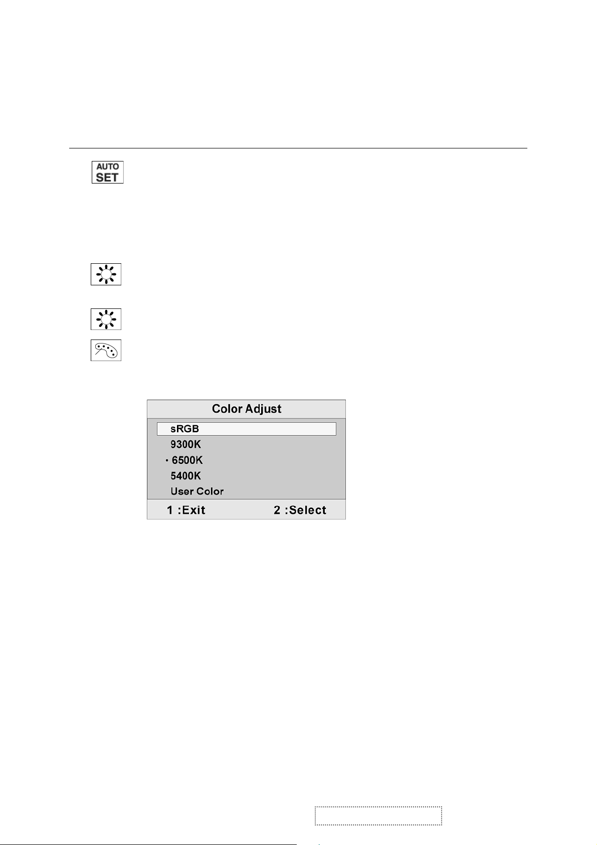
Color Adjust provides several color adjustment modes, including preset color
temperatures and a User Color mode which allows independent adjustment of
red (R), green (G), and blue (B). The factory setting for this product is 6500K
(6500 Kelvin).
sRGB-This is quickly becoming the industry standard for color management,
with support being included in many of the latest applications. Enabling this
setting allows the LCD display to more accurately display colors the way they
were originally intended. Enabling the sRGB setting will cause the Contrast and
Brightness adjustments to be disabled.
9300K-Adds blue to the screen image for cooler white (used in most office
settings with fluorescent lighting).
6500K-Adds red to the screen image for warmer white and richer red.
5400K-Adds green to the screen image for a darker color.
ViewSonic Corporation Confidential - Do Not Copy VA703b-1_VA703m-1
8
Page 12
Control Explanation
User Color Individual adjustments for red (R), green (G), and blue (B).
1. To select color (R, G or B) press button [2].
2. To adjust selected color, pressSandT.
Important: If you select RECALL from the Main Menu when the product is
set to a Preset Timing Mode, colors return to the 6500K factory preset.
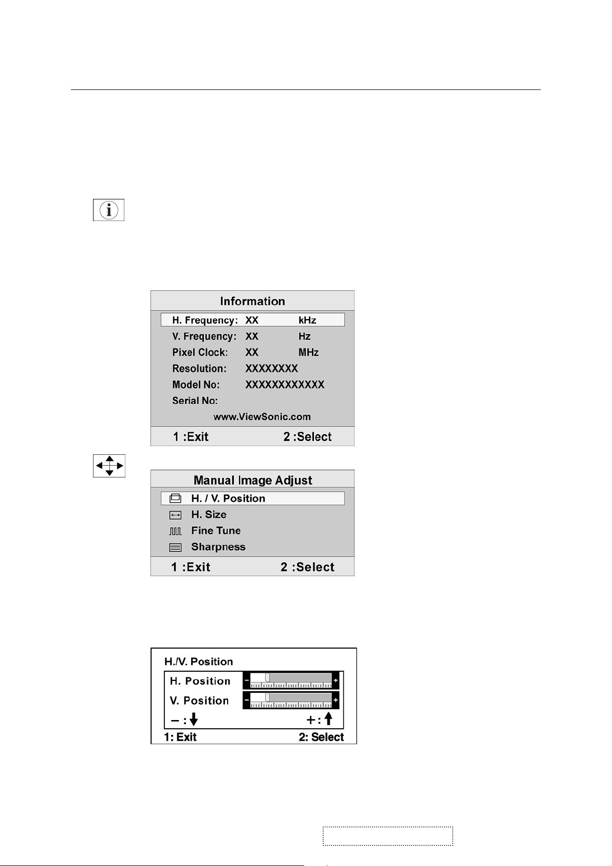
Information displays the timing mode (video signal input) coming from the
graphics card in the computer, the LCD model number, the serial number, and
the ViewSonic® website URL. See your graphics card’s user guide for
instructions on changing the resolution and refresh rate (vertical frequency).
NOTE: VESA 1280 x 1024 @ 60Hz (recommended) means that the resolution
is 1280 x 1024 and the refresh rate is 60 Hertz.
Manual Image Adjust displays the Manual Image Adjust menu.
H. Size (Horizontal Size) adjusts the width of the screen image.
H./V. Position (Horizontal/Vertical Position) moves the screen image left or
right and up or down.
ViewSonic Corporation Confidential - Do Not Copy VA703b-1_VA703m-1
9
Page 13

Control Explanation
Fine Tune sharpens the focus by aligning text and/or graphics with pixel
boundaries.
NOTE: Try Auto Image Adjust first.
Sharpness adjusts the clarity and focus of the screen image.
Setup Menu displays the menu shown below:
Language Select allows the user to choose the language used in the menus and
control screens.
Resolution Notice displays the Resolution Notice menu shown below.
Resolution Notice advises the optimal resolution to use.
OSD Position allows the user to move the OSD menus and control screens.
OSD Timeout sets the length of time the OSD screen is displayed. For example,
with a “15 second” setting, if a control is not pushed within 15 seconds, the
display screen disappears.
OSD Background allows the user to turn the OSD background On or Off.
Memory Recall returns the adjustments back to factory settings if the display is
operating in a factory Preset Timing Mode listed in the Specifications of this
manual.
Exception: This control does not affect changes made with the User Color
control, Language Select or Power Lock setting.
0
1
ViewSonic Corporation Confidential - Do Not Copy VA703b-1_VA703m-1
Page 14
SHORT CUTS FUNCTION FROM THE BUTTONS
[1]
Main Menu
[2]
[▼] or [▲]
[▼] + [▲]
[1] + [2]
[1] + [▼] + [▲]
(keep pushing 5 sec)
[1] + [▼]
[1] + [▲]
Auto Image Adjust
To immediately activate Contrast menu. It should be
change to Brightness OSD by push button [2]
recall both of Contrast and Brightness to default
toggle 720x400 and 640x400 mode when input 720x400
or 640x400 mode
White Balance (Not shown on user’s guide)
Power Lock
OSD Lock
Remark : All the short cuts function are only available while OSD off
1
1
ViewSonic Corporation Confidential - Do Not Copy VA703b-1_VA703m-1
Page 15
4. Circuit Description
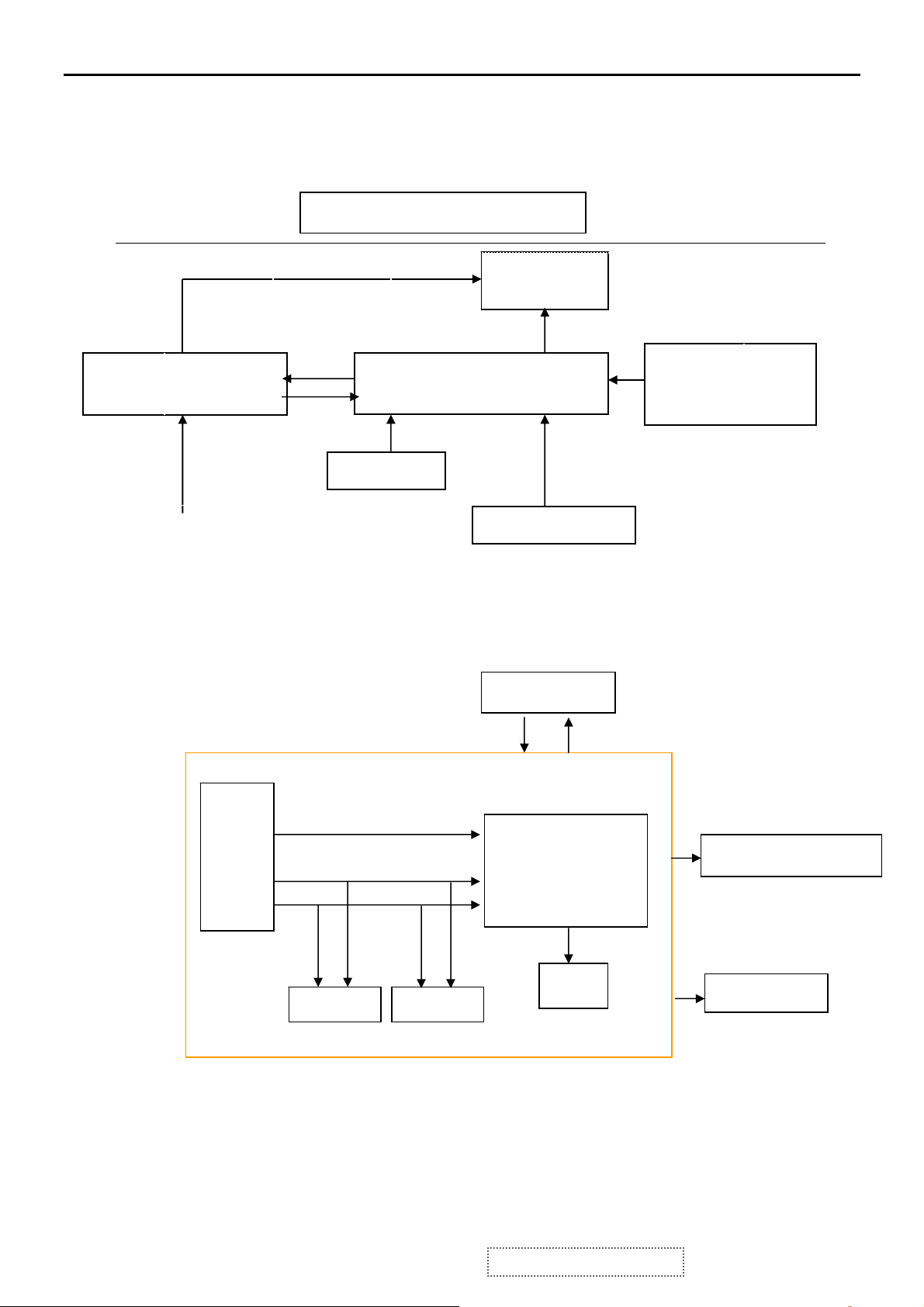
4.1 LCD MONITOR DESCRIPTION
The LCD MONITOR will contain a Main Board, an Power Board, Key Board which
house the flat panel control logic, brightness control logic and DDC.
Monitor Block Diagram
Power Board
(Include: adapter, inverter)
AC-IN
100V-240V
4.2 MAIN BOARD BLOCK FUNCTION DESCRIPTION
The main board contains panel control logic, brightness control logic, DDC and DC
convert DC circuit and so on.
R
G
B
H
V
SDA
SCL
CCFL Drive.
Key Board
EPROM EPROM
Flat Panel and
CCFL backlight
Main Board
HOST Computer
PWPC board
TSUM16AK
OSC
RS232 Connector
For white balance
adjustment in factory
mode
Video signal, DDC
Backlight and Panel
Keyboard
2
1
ViewSonic Corporation Confidential - Do Not Copy VA703b-1_VA703m-1
Page 16
4.3 PWPC BOARD BLOCK FUNCTION DESCRIPTION
PWPC board combines to adapter and inverter, Adapter which commonly consists
of bridge rectifier and filter, start circuit, PWM control circuit, protection circuits and
convert to 12V, 5V DC voltage by input 90V-240V AC voltage that provide power supply
for each chips in the main board and inverter. Inverter is DC TO AC circuit. It changes
the 12v DC of power supply to about 600-800v AC that drives the backlight. It mostly
consists of starting circuit, PWM controller, DC changing circuit, LC surging circuit,
output circuit and protection circuit etc.
AC input
EMI filter
Lamp
OSC and
Output
Circuit
Feedback
Circuit
Bridge
Rectifier
and Filter
Start Circuit
R903, R904,R905
PWM
Control IC
DC Convert
Circuit
Over
Voltage
Transformer
MOSFET
Q203
PWM
Control IC
Rectifier
CMOS
Over
Vol tage
Protect
CN902
5V
12V
ON/OF
ON/OFF
Control
DIM
3
1
ViewSonic Corporation Confidential - Do Not Copy VA703b-1_VA703m-1
Page 17
4.4 INTRODUCTION OF IC
TSUM16AK(U401): integrate ADC, OSD, SCALER, MCU, LVDS, convert analog RGB
into digital and room and shrink scaling output to LCD panel.
PIN Function:
Pin Symbol Description
70 SDO SPI flash serial data output; Input w/5V-tolerant
71 CSZ SPI flash chip select; output
72 SCK SPI flash serial select; output
73 SDI SPI flash serial data input; output
65 DDCA_SDA/RS232_TX DDC data for analog interface; 4mA driving
66 DDCA_SDA/RS232_RX DDC data for analog interface/UART
19 RST Chip reset; High reset; Input w/5V-tolerant
22 RSTN Chip reset; Low reset; Input w/5W-toerant
11 VCTRL Regulator control; Output
63 HSYNCO Analog HSYNC input
64 VSYNCO Analog VSYNC input
62 REFP Internal ADC top de-coupling pin
61 REFM Internal ADC bottom de-coupling pin
51 REXT
21 PWM1 PWM1; 4mA driving strength; Output
29 PWM0 PWM0; 4mA driving strength; Output
4 BYPASS For External Bypass Capacitor
32 XIN Xin; Crystal Oscillator Input
33 XOUT Xout; Crystal Oscillator Output
44、50、60 AVDD_ADC
52
34
14、67、95、
103、115
12、68、97、
117
AIC1084-33PM (U702): DC power convert, used to 5v convert 3.3v.
LT1117-18(U701): DC power convert, used to 5v convert 3.3v.
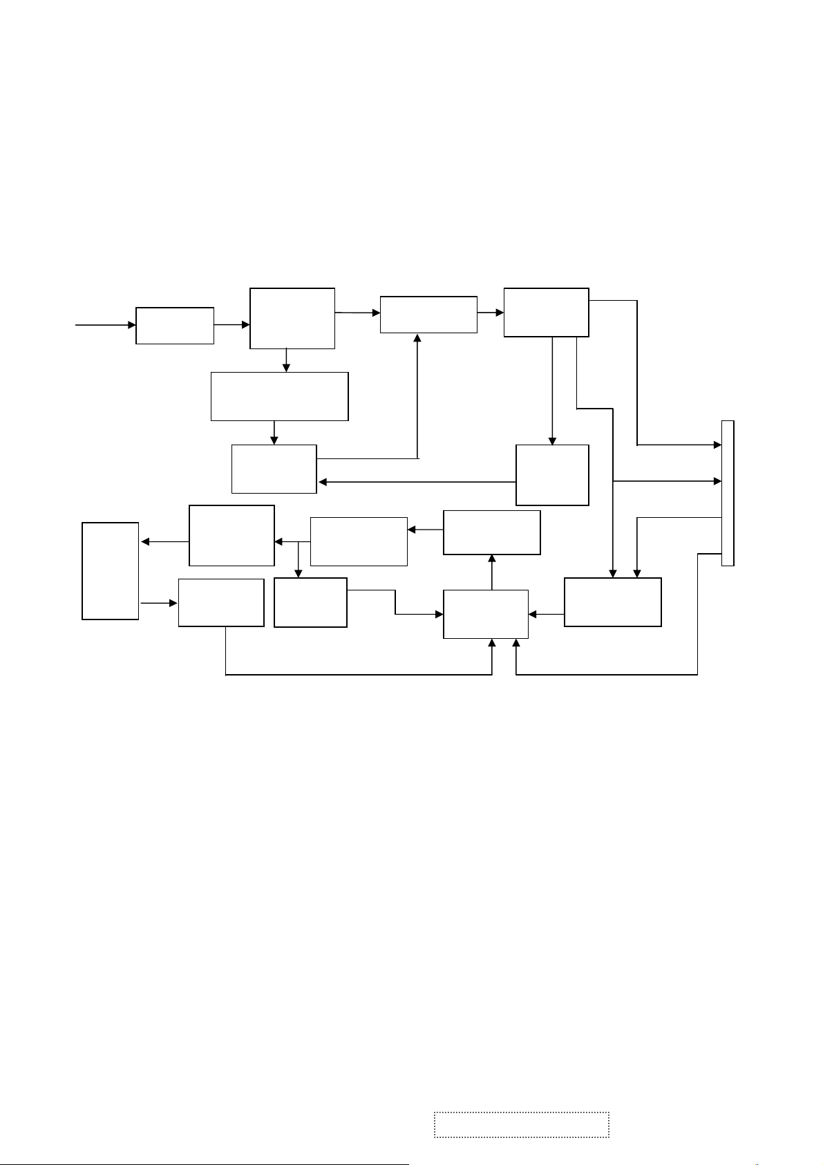
PM25LV010-25SCE (U402): The PM25LV010 are 512 Kbit/1 Mbits 3.0 Volt-only serial
Flash memories. These devices are designed to use a single low voltage,
ranging from 2.7 Volt to 3.6 Volt for 25MHz or from 3.0 Volt to 3.6 Volt for 33MHz
to perform read, erase and program operations. The devices can be programmed
in standard EPROM programmers as well.
AVDD_PLL
AVDD_MPLL
strength/UART transmitter/GPIO; I/O w/5V-tolrant
transmitter/GPIO; Input w/5V-tolrant
External resistor 390 ohm to AVDD_ADC
ADC Power 3.3V
PLL Power 3.3V
MPLL Power 3.3V
VDDP Digital Output Power 3.3V
VDDC Digital Core Power 1.8V
4
1
ViewSonic Corporation Confidential - Do Not Copy VA703b-1_VA703m-1
Page 18
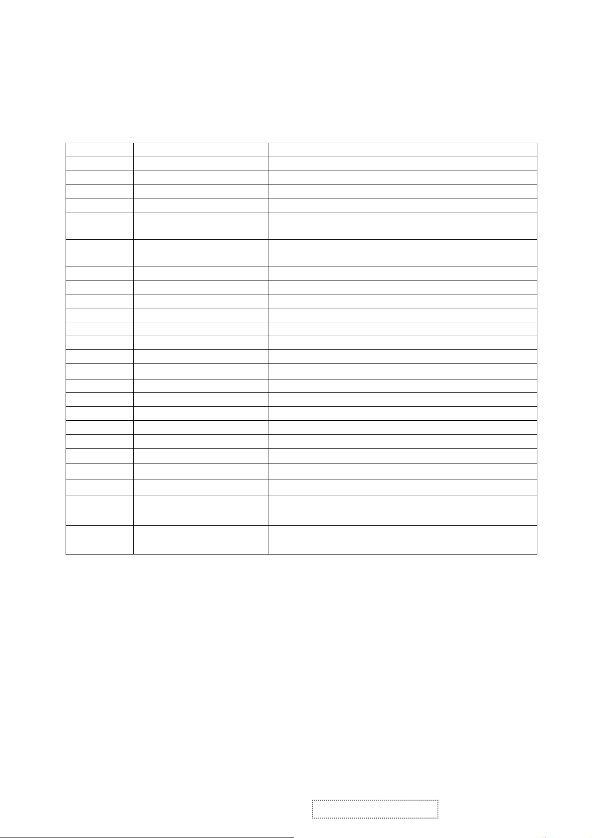
PIN Descriptions:
Symbol Type Description
CE# INPUT Chip Enable: CE# goes low activates the device’s internal
circuitries for device operation. CE# goes high deselects the
device and switches into standby mode to reduce the power
consumption. When the device is not selected, data will not be
accepted via the serial input pin (SI), and the serial output pin
(SO) will remain in a high impedance state.
SCK INPUT Serial Data Clock
SI INPUT Serial Data Input
SO OUTPUT Serial Data Output
GND Ground
Vcc Device Power Supply
WP# INPUT
HOLD# INPUT
Write Protect: When the WP# pin brought to low and WPEN bit is
“1”, all write operations to the status register are inhibited.
Hold: Pause serial communication with the master device without
resetting the serial sequence.
Circuit Diagram
5
1
ViewSonic Corporation Confidential - Do Not Copy VA703b-1_VA703m-1
Page 19
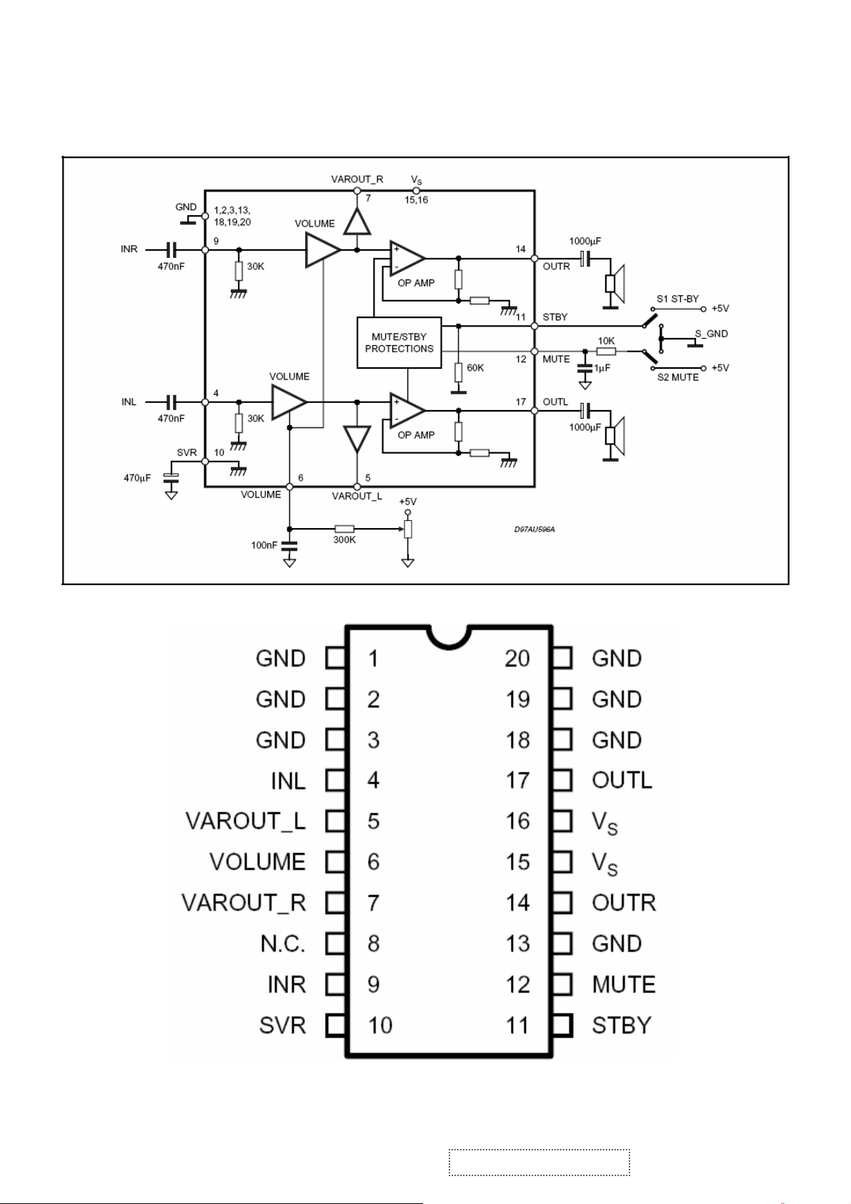
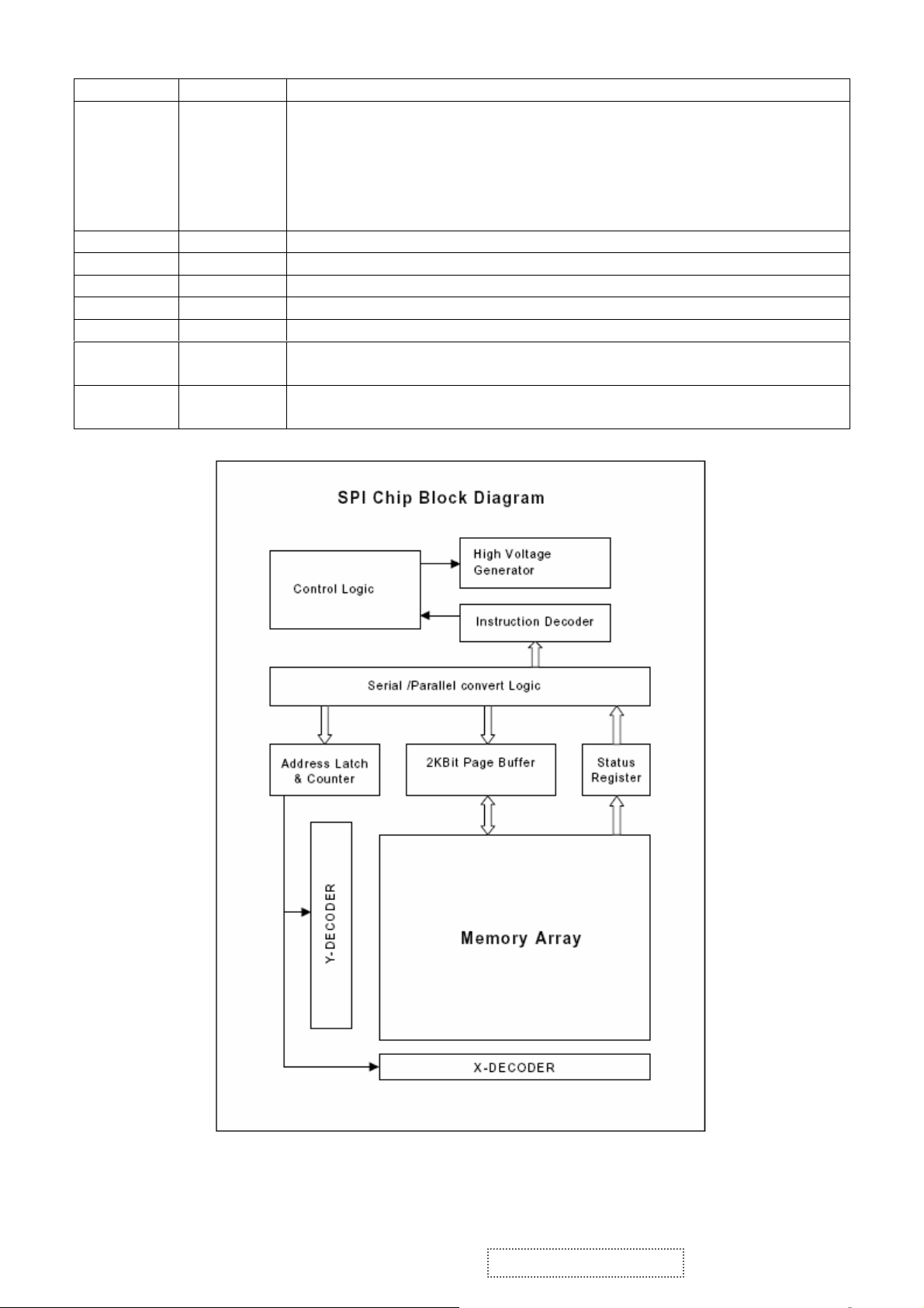
TDA7496L(U201): The TDA7496L is a stereo 2W+2W class AB power amplifier, specially
designed for high quality sound, TV and Monitor applications. Features of the UTC
TDA7496L include linear volume control, Stand-by and mute functions. The function
of each pin and the inside circuit diagram are as follows:
Block Diagram
PIN Function
6
1
ViewSonic Corporation Confidential - Do Not Copy VA703b-1_VA703m-1
Page 20
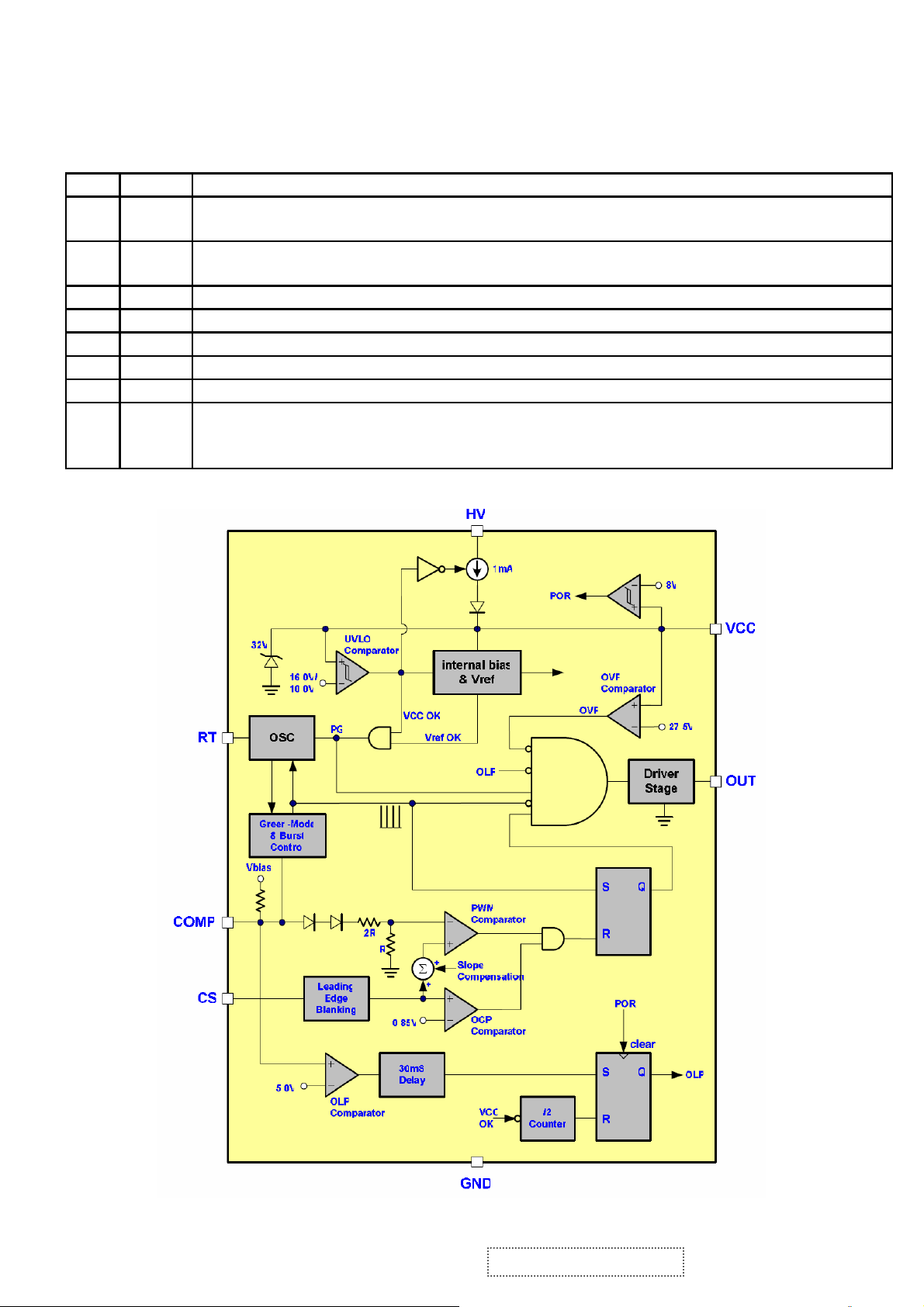
LD7575 PS (IC901): The LD7575 is a current-mode PWM controller with excellent
power-saving operation. The embedded over voltage protection, over load protection
and the special green-mode control provide the solution for users to design a high
performance power circuit easily and etc. The function of each pin and the inside circuit
diagram are as follows:
PIN Descriptions:
Pin Name Function
1 RT
2 COMP
This pin is to program the switching frequency. By connection a resistor to ground
to set the switching frequency.
Voltage feedback pin(same as the COMP pin in UC384X), By connecting a
photo-coupler to close the control loop and achieve the regulation.
3 CS Current sense pin, connect to sense the MOSFET current
4 GND Ground
5 OUT Gate drive output to drive the external MOSFET
6 VCC Supply voltage pin
7 NC Unconnected Pin
Connect this pin to positive of bulk capacitor to provide the startup current for the
8 HV
controller, when Vcc voltage trips the UVLO(on), this HV loop will be off to save
the power loss on the startup circuit.
Block Diagram
7
1
ViewSonic Corporation Confidential - Do Not Copy VA703b-1_VA703m-1
Page 21

OZ9938GN(IC801): The OZ9938 is high performance, cost-effective CCFL controller designed
for driving large-size LCD applications requiring 2 to 6 CCFLs.PWM control, Has such
functions as short-voltage protection, Over-voltage protection, over-current protection
and etc. The function of each pin and the circuit diagram inside are as follows:
PIN Descriptions:
Pin Names Description
1 DRV1 Drive output
2 VDDA Supply voltage input
3 TIMER Timing capacitor to set striking time and shutdown delay time
4 DIM
Analog dimming or Internal LPWM dimming or external PWM pulse
input for dimming function
5 ISEN Current sense feedback
6 VSEN Voltage sense feedback
7 OVPT Over-voltage/ over-current protection threshold setting pin
8 NC No connection
9 NC No connection
10 ENA ON/OFF control of IC
11 LCT
Timing capacitor to set internal PWM dimming frequency and also a
pin for analog dimming selection
12 SSECMP Capacitor for soft start time and loop compensation
13 CT Timing resistor and capacitor for operation and striking frequency
14 GNDA Ground for analog signals
15 DRV2 Drive output
16 PGND Ground for power paths
8
1
ViewSonic Corporation Confidential - Do Not Copy VA703b-1_VA703m-1
Page 22
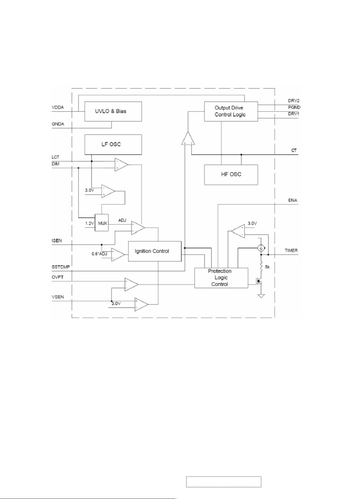
Block Diagram
ViewSonic Corporation Confidential - Do Not Copy VA703b-1_VA703m-1
19
Page 23

5. Adjustment Procedure
5.1 ADJUSTMENT CONDITIONS AND PRECAUTIONS
1. Approximately 30 minutes should be allowed for warm up before proceeding.
2. Adjustments should be undertaken only on those necessary elements since most of them
have been carefully preset at the factory.
3. ESD protection is needed before adjustment.
5.2 MAIN ADJUSTMENTS
NO. FUNCTIONS DESIGNATION
1. White Balance Function Key
2. Geometry Function Key
5.3 ALIGNMENT PROCEDURES
Approximately 30 minutes should be allowed for warm up before proceeding
White-Balance adjustment.
1. Adjust of White Balance
1.)How to do the Chroma-7120 MEM .Channel setting
A、Reference to chroma 7120 user guide
B、Use “ SC” key and “ NEXT” key to modify xyY value and use “ID” key to modify the
TEXT description Following is the procedure to do white-balance adjust
2.)Setting the color temp. You want
A、MEM.CHANNEL9 ( 9300 color):
9300 color temp. parameter is Wx = 0.283 ±0.03;Wy = 0.298 ±0.03;
Y = 250 ±20 cd/m
B、MEM.CHANNEL10 ( 6500 color):
6500 color temp. parameter is Wx = 0.313±0.03;Wy = 0.329 ±0.03;
Y = 260 ±20 cd/m
C、MEM.CHANNEL 11 ( 5400 color):
5400 color temp. parameter is Wx = 0.335±0.03;Wy = 0.350 ±0.03;
Y = 250 ±20 cd/m
D、MEM.CHANNEL10 ( SRGB color):
6500 color temp. parameter is Wx = 0.313±0.03;Wy = 0.329 ±0.03;
Y = 220 ±20 cd/m
2 ,
2,
2,
2,
ViewSonic Corporation Confidential - Do Not Copy VA703b-1_VA703m-1
20
Page 24

3.)Into factory mode of VA503b/VA503m
A、First Power off, then press Switch 2 button along with press Power button will activate
the factory mode, then MCU will do AUTO LEVEL automatically. Meanwhile press
MENU the OSD screen will located at LEFT TOP OF PANEL.
4.)Bias adjustment :
Set the Contrast
Adjust the Brig htness
to 70
to 100.
5.)Gain adjustment :
Move cursor to “-F-” and press MENU key
A、Adjust 9300 color-temperature
(1)、Switch the Chroma-7120 to RGB-Mode (with press “MODE” button )
(2)、Switch the MEM. channel to Channel 9 ( with up or down arrow on chroma 7120 )
(3)、The LCD-indicator on chroma 7120 will show x = 0.283 ±0.03, y =0.298 ±0.03,
2
Y = 250 ±20 cd/m
(4)、Adjust the RED of color1 on factory window until chroma 7120 indicator reached
the value R=100
(5)、Adjust the GREEN of color1 on factory window until chroma 7120 indicator reached
the value G=100
(6)、Adjust the BLUE of color1 on factory window until chroma 7120 indicator reached
the value B=100
(7)、Repeat above procedure ( item 4,5,6) until chroma 7120 RGB value meet the
tolerance =100±5
B、Adjust 6500 color-temperature
(1)、Switch the chroma-7120 to RGB-Mode (with press “MODE” button )
(2)、Switch the MEM .channel to Channel 10( with up or down arrow on chroma 7120 )
(3)、The LCD-indicator on chroma 7120 will show x = 0.313 ±0.03, y = 0.329 ±0.03, Y =
260 ±20 cd/m
2
(4)、Adjust the RED of color3 on factory window until chroma 7120 indicator reached
the value R=100
(5)、Adjust the GREEN of color3 on factory window until chroma 7120 indicator reached
the value G=100
(6)、Adjust the BLUE of color3 on factory window until chroma 7120 indicator reached
the value B=100
(7)、Repeat above procedure ( item 4,5,6) until chroma 7120 RGB value meet the
tolerance =100±5
ViewSonic Corporation Confidential - Do Not Copy VA703b-1_VA703m-1
21
Page 25

C、Adjust 5400 color-temperature
(1) Switch the chroma-7120 to RGB-Mode (with press “MODE” button )
(2)、Switch the MEM .channel to Channel 11( with up or down arrow on chroma 7120 )
(3)、The LCD-indicator on chroma 7120 will show x = 0.335 ±0.03, y = 0.350 ±0.03, Y =
250 ±20 cd/m
(4)、Adjust the RED of color3 on factory window until chroma 7120 indicator reached the
value R=100
(5)、Adjust the GREEN of color3 on factory window until chroma 7120 indicator reached
the value G=100
(6)、Adjust the BLUE of color3 on factory window until chroma 7120 indicator reached
the value B=100
(7)、Repeat above procedure ( item 4,5,6) until chroma 7120 RGB value meet the
tolerance =100±5
D、Adjust SRGB color-temperature
(1)、Switch the chroma-7120 to RGB-Mode (with press “MODE” button )
(2)、Switch the MEM .channel to Channel 10( with up or down arrow on chroma 7120 )
(3)、The LCD-indicator on chroma 7120 will show x = 0.313 ±0.03, y = 0.329 ±0.03, Y =
220 ±20 cd/m
(4)、Adjust the RED of color3 on factory window until chroma 7120 indicator reached
the value R=100
(5)、Adjust the GREEN of color3 on factory window until chroma 7120 indicator reached
the value G=100
(6)、Adjust the BLUE of color3 on factory window until chroma 7120 indicator reached
the value B=100
(7)、Repeat above procedure ( item 4,5,6) until chroma 7120 RGB value meet the
tolerance =100±5
E、Press reset key and Turn the Power-button “off to on” to quit from factory mode.
2. Geometry
1).Set cross-hatch pattern and preset timing as timing table listed.
2).Change to each mode in turn and wait for the monitor finish auto-alignment and save
press before change to next mode.
3).Until all of modes are adjusted,exit OSD menu and press POWER OFF to exit factory
mode.
2
2
ViewSonic Corporation Confidential - Do Not Copy VA703b-1_VA703m-1
22
Page 26

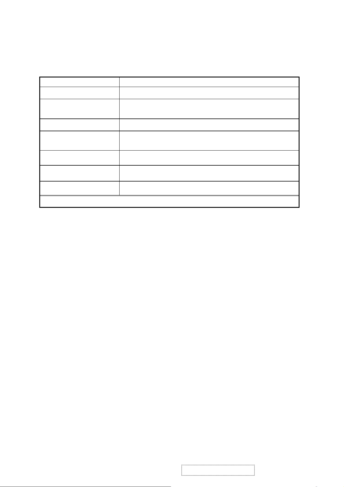
5.4 Factory Defaults
Item Defaults Item Defaults
Contrast 70% Volume 50%
Brightness 100% Balance N/A
Color Temperature 6500K Treble N/A
Sharpness 0% Bass N/A
OSD H. Position 50% 720x400/640x400 720x400
OSD V. Position 50% 640x480@60Hz
OSD Time Out 15 Sec In SOG and Composite,
OSD Background Enabled In SOG and Composite,
Resolution Notice Enabled In SOG and Composite,
5.5 Function Test
(For VA703m only)
640x480@60Hz
720x480@60Hz
N/A
720x480@60Hz
640x480@60Hz
N/A
1152x864@75Hz
1152x870@75Hz
N/A
1280x768@60/75/85Hz
1024x768@60/75/85Hz
1 Product: 17” LCD Monitor
2 Test Equipment: Color Video Signal & Pattern (or PC with SXGA resolution and a
sound card)
3 Test Condition: Before function test and alignment, each LCD Monitor should be
warmed up for at least 30 minutes with the following conditions:
(a)In room temperature,
(b) With full-white screen, RGB, and Black
(c) With cycled display modes,
640*480 (H=43.27kHz, V=85Hz)
800*600 (H=53.7kHz, V=85Hz)
1024*768 (H=68.67kHz, V=85Hz)
1280*1024 (H=79.97kHz, V=75Hz)
4 Test Display Modes & Pattern
Compatible Modes
Item Timing Analog
1 640 x 350 @ 70Hz, 31.5kHz
2 640 x 480 @ 50Hz
3 640 x 480 @ 60Hz, 31.5kHz
4 640 x 480 @ 67Hz, 35.0kHz
5 640 x 480 @ 72Hz, 37.9kHz
6 640 x 480 @ 75Hz, 37.5kHz
7 640 x 480 @ 85Hz, 43.27kHz
8 720 x 400 @ 70Hz, 31.5kHz
9 800 x 600 @ 56Hz, 35.1kHz
Yes
Yes
Yes
Yes
Yes
Yes
Yes
Yes
Yes
ViewSonic Corporation Confidential - Do Not Copy VA703b-1_VA703m-1
23
Page 27

10 800 x 600 @ 60Hz, 37.9kHz
11 800 x 600 @ 72Hz, 48.1kHz
12 800 x 600 @ 75Hz, 46.9kHz
13 800 x 600 @ 85Hz, 53.7kHz
14 832 x 624 @ 75Hz, 49.7kHz
15 1024 x 768 @ 60Hz, 48.4kHz Yes
16 1024 x 768 @ 70Hz, 56.5kHz
17 1024 x 768 @ 72Hz, 58.1kHz
18 1024 x 768 @ 75Hz, 60.0kHz
19 1024 x 768 @ 85Hz
20 1152 x 864 @ 75Hz
21 1152 x 870 @ 75Hz
22 1280 x 720 @ 60Hz
23 1280 x 960 @ 60Hz
24 1280 x 960 @75Hz
25 1280 x 1024 @ 60Hz
26 1280 x 1024 @ 75Hz
Yes
Yes
Yes
Yes
Yes
Yes
Yes
Yes
Yes
Yes
Yes
Yes
Yes
Yes
Yes
Yes
Function Test Display Pattern
Item Test Content Pattern Specification Remark
1
2
3 Boundary
4
Frequency &
Tracking
Contrast/Bright
ness
Fine Line Moire
16 Gray Scale
Horizontal&Vertical
Thickness
RGB Color
Performance
RGB Color Intensities
Screen
5
Uniformity &
Full White
Flicker
6
Dead
Pixel/Line
White Screen & Dark
Screen
7 White Balance White & Black Pattern
Eliminate visual wavy
noise.
16 gray levels sh should
be distinguishable.
Figure 1
Figure 2
Horizontal and Vertical
position of video should
be adjustable to be
Figure 3
within the screen frame.
Contrast of each R, G,
B, color should be
normal.
Should be compliant
with the spec.
Figure
4,5,6
Figure 7
The numbers of dead
pixels should be
Figure 7,8
compliant with the spec.
The screen must have
the pure white and black
Figure 9
pattern, no other color.
ViewSonic Corporation Confidential - Do Not Copy VA703b-1_VA703m-1
24
Page 28

Fine Line Morie Pattern (Figure1) Gray Scale Pattern (Figure2)
Horizontal & Vertical Thickness Pattern R. Color Pattern (Figure 4)
(Figure 3)
G. Color Pattern (Figure 5) B. Color Pattern (Figure 6)
ViewSonic Corporation Confidential - Do Not Copy VA703b-1_VA703m-1
25
Page 29

Full White Pattern (Figure 7) Dark Screen Pattern (Figure 8)
Black-White Pattern (Figure 9)
4.3 Function Test and Alignment Procedure
All Modes Reset
You should do “All Mode Reset” (Refer to Chapter III-3. Hot Keys for Function
Controls) first. This action will allow you to erase all end-user’s settings and restore
the factory defaults.
Auto Image Adjust
Please select and enter “Auto Image Adjust” function on Main Menu to see if it is
workable. The “Auto Image Adjust” function is aimed to offer a better screen quality
by built-in ASIC. For optimum screen quality, the user has to adjust each function
manually.
Firmware
Test Pattern: Burn In Mode (Refer to Chapter III-3. Hot Keys for Function Controls)
- Make sure the F/W is the latest version.
DDC
Test Pattern: EDID program
Make sure it can pass test program.
Fine Tune and Sharpness
Test Signal: 1280*1024@60Hz
Test Pattern: Line Moire Pattern
Check and see if the image has noise and focus performs well. Eliminate visual
ViewSonic Corporation Confidential - Do Not Copy VA703b-1_VA703m-1
26
Page 30

line bar.
If not, readjust by the following steps:
(a)Select and enter “Fine Tune” function on “Manual Image Adjust” to adjust the
image to eliminate visual wavy noise.
(b)Then, select and enter “Sharpness” function to adjust the clarity and focus of
the screen image.
Boundary
Test Signal: 1280*1024@60Hz
Test Pattern: Horizontal & Vertical Line Thickness Pattern
Check and see if the image boundary is within the screen frame.
If not, readjust by the following steps:
(a)Select and enter “Manual Image Adjust” function on OSD Main Menu.
(b)Then, select and enter “Horizontal Size” or “Horizontal/Vertical Position” function
to adjust the video boundary to be full scanned and within screen frame.
White Balance
Test Signal: 640*480@60Hz
Test Pattern: White and Black Pattern
1.5.8 R, G, B, Colors Contrast
Test Signal: 1280*1024@60Hz
Test Pattern: R, G, B, Color Intensities Pattern and 16 Gray Scale Pattern
- Check and see if each color is normal and distinguishable.
- If not, please return the unit to repair area.
Screen Uniformity and Flicker
Test Signal: 1280*1024@60Hz
Test Pattern: Full White Pattern
- Check and see if it is in normal condition.
1.5.10 Dead Pixel and Line
Test Signal: 1280*1024@60Hz
Test Pattern: Dark and White Screen Pattern
- Check and see if there are dead pixels on LCD panel with shadow gauge and
filter film.
- The total numbers and distance of dead pixels should be compliant with the
spec.
Mura
Test Pattern: White, RGB, Black, & Grey
Test Tool: 10% ND Filter
- Check if the Mura can pass 10% ND Filter.
Audio
Test Signal: Voice signal (optional, depend on model)
Test Pattern: liberty
- Make sure there is audio output.
- Make sure that audio function (volume 80%) is working without noise and
resonance.
- Make sure that the sound of right and left speakers are in balance.
Check for Secondary Display Modes
Test Signal:
Analog: 640*350@70Hz; 640*480@60/67/72/75/85Hz;
ViewSonic Corporation Confidential - Do Not Copy VA703b-1_VA703m-1
27
Page 31

720*400@70Hz; 800*600@56/60/72/75/85Hz;
832*624@75Hz, 1024*768@60/70/72/75/85Hz;
1280*1024@60/75Hz
- Normally when the primary mode 1280*1024@60Hz is well adjusted and
compliant with the specification, the secondary display modes will also be
compliant with the spec. But we still have to check with the general test pattern to
make sure every secondary is compliant with the specification.
All Modes Reset
After final QC step, we have to erase all saved changes again and restore the
factory defaults. You should do “All Mode Reset” again.
Power Off Monitor
Turn off the monitor by pressing “Power” button.
5.6 Firmware Upgrade Procedure
When you receive the returned monitor, please check whether the firmware version is
the latest. If not, please do the following procedures to upgrade it to the latest version.
1 Equipment Needed
- VA503/VA703/VA903 Monitor
- Fixture for Firmware Upgrade
- Power Adapter (P/N: 47.58201.001) *1 for Fixture
- VGA Cable (P/N: 42.59901.003) *1(Pin 4, 11 should be connected to GND)
- PC (Personal Computer)
- LPT Cable (P/N: 42.59906.001) *1
- Firmware Upgrade Program
- One additional monitor for checking the program execution
ViewSonic Corporation Confidential - Do Not Copy VA703b-1_VA703m-1
28
Page 32

2 Setup Procedure
2.1 Connect P2 of Fixture with printer port of PC by LPT Cable.
2.2 Connect P1 of Fixture with VA503/VA703/VA903 Monitor by VGA Cable.
2.3 Plug Power Adapter to Fixture.
2.4 Connect Power Cord to VA503/VA703/VA903 Monitor.
2.5 Connect P3 to the Signal Generator (eg.Chroma2326) for verifying it after the
operation being completed.
2.6 Connect PC to the additional monitor.
JP1:to Power Adapter
P1:to VGA Cable
P2:to LPT Cable
P3:to Signal Generator
3 Firmware Upgrade Procedure
Step 1. Let VA503/VA703/VA903 set to be connected with AC cable and VGA cable.
Step 2.Execute the MSstar ISP tool.
ViewSonic Corporation Confidential - Do Not Copy VA703b-1_VA703m-1
29
Page 33

Step 3. Click “Config” button . Select the Port Type: LPT1 and the Base Addr : 0x378
on “Communication Setting” flame, and then the Speed: 47 on “E2PROM Device
Setting” flame
Step 4. Click “Connect” button. (On this step, if the connection is successful, the “Entry
ISP Mode” Dialog will be showed. If not, the error dialog will be done.)
ViewSonic Corporation Confidential - Do Not Copy VA703b-1_VA703m-1
30
Page 34

Step 5. Click “Device” button. Select the “PMC25LV010” or “SST25VF010” viewed on
your set.
Step 6. Click “Read” button. Select the object bincode on your corresponding directory.
Step 7. Click “Auto” button. Execute the flashing action by clicking the “Run” button.
ViewSonic Corporation Confidential - Do Not Copy VA703b-1_VA703m-1
31
Page 35

Step 8. If the flashing F/W has been completed, “Ok” message will be showed on the
right TextBox.
Step 9. Unplug and replug power cord of VA503/VA703/VA903 set and then check the
OSD operation and image on srceen.
Step 10. At last, do “Memory Recall.”
3.2 Setup Procedure
3.2.1 Connect P2 and monitor of Fixture with VGA ports of VA503/VA703/VA903 by
VGA Cable.
3.2.2 Connect P1 of Fixture with Printer port of PC by LPT Cable.
3.2.3 Plug Power Adapter to Fixture.
3.2.4 Connect Power Cord to VA503/VA703/VA903 Monitor.
3.2.5 Connect PC to the additional monitor.
JP1: Power Adapter
P2: VGA Cable
P1:to LTP Cable
ViewSonic Corporation Confidential - Do Not Copy VA703b-1_VA703m-1
32
Page 36

3.3 DDC Key In Procedure
Sep1.Select and execute DDc Key In program
ViewSonic Corporation Confidential - Do Not Copy VA703b-1_VA703m-1
33
Page 37

Sep2:Inpute the S/N and execute “Enter”
ViewSonic Corporation Confidential - Do Not Copy VA703b-1_VA703m-1
34
Page 38

ViewSonic Corporation Confidential - Do Not Copy VA703b-1_VA703m-1
35
Page 39

Sep3:Key the “Enter” and write the data
ViewSonic Corporation Confidential - Do Not Copy VA703b-1_VA703m-1
36
Page 40

Sep4:If ddc program OK and show “data compare ok”
ViewSonic Corporation Confidential - Do Not Copy VA703b-1_VA703m-1
37
Page 41

Disassemble Process
1 Units Disassemble Process
1.1 Tools
Glove
Big cross screwdriver
Small cross screwdriver
Prize equipment or abandoned IC card
Screw box
Cushion
Six angle sleeve spanner
1.2 Disassemble process
1、 Tide up the worktable, spread straight cushion, put the monitor on it, the front side
adown.(Picture 1)
2、 Remove the decorate slice of the back cover.(Picture 2, 3)
3、 Disassemble the 4 screws that fix the stand, remove the stand..(Picture, 4)
4、 Disassemble the 4 screws of the back cover.(Picture 5)
5、 Use equipment or abandoned IC card to prize up the bezel through the bottom flute,
and rip up the bezel downwards.( as showed in the following the picture 6,7,8)
6、 Disassemble the 3 screws and 3 pins of the Key board, remove the Key board. ( as
showed in the following the picture 9,10)
7、 Remove the back cover, refer to the following picture 11.
8、 Disassemble the 6 fixed screw in the shield, remove the shield as the direction
arrowhead showed, refer to the following picture 12.
9、 Disassemble the 5 screws and 5 pins of the PWPC board, remove the PWPC
board.(symbolized the following picture 13 with red color)
10、 Disassemble the 2 screws and 1 pins of the audio board, remove the audio board.
(symbolized the following picture 13 with yellow color)
11、 Disassemble the 3 screws and 2 pins of the main board, remove the main board.
(symbolized the following picture 13,14 with blue color)
12、 Disassemble the 4 fixed screws of the panel, remove the main frame, as showed in
the following the picture 15,16,17. Do not damage the cable of the panel.
13
、 That’s all. The disassemble process of the unit is over.
ViewSonic Corporation Confidential - Do Not Copy VA703b-1_VA703m-1
38
Page 42

1.3 Show pictures:
(Picture 1) (Picture 2)
(Picture 3) (Picture 4)
(Picture 5) (Picture 6)
ViewSonic Corporation Confidential - Do Not Copy VA703b-1_VA703m-1
39
Page 43

(Picture 7) (Picture 8)
(Picture 9) (Picture 10)
(Picture 11) (Picture 12)
ViewSonic Corporation Confidential - Do Not Copy VA703b-1_VA703m-1
40
Page 44

(Picture 13)
(Picture 14)
(Picture 15)
(Picture 16)
ViewSonic Corporation Confidential - Do Not Copy VA703b-1_VA703m-1
41
Page 45

(Picture 17)
ViewSonic Corporation Confidential - Do Not Copy VA703b-1_VA703m-1
42
Page 46

Packing Procedure
ViewSonic Corporation Confidential - Do Not Copy VA703b-1_VA703m-1
43
Page 47

6. Troubleshooting Flow Chart
ViewSonic Corporation Confidential - Do Not Copy VA703b-1_VA703m-1
44
Page 48

7. Recommended Spare Parts List
d
S
ViewSonic Model Number: VS11280
RECOMMENDED SPARE PARTS LIST (VA703b-1)
Serial No. Prefix: Q85 Rev: 1b
Item ECR/ECN ViewSonic P/N Ref. P/N Location Universal number#
1 Accessories: Power Cor
2 Key Board B-00005797 KEPC560KE1P
PC Board Assembly:
3 Sub Board - Conversion Board B-00006634 CBPC780KK5VWP
4 Sub Board - Conversion Board For CPT panel Added on 10/20/06 B-00008144 CBPC780KC5VWP
5 Power Supply Board B-00006635 PWPC1742HDV3P
6 Power Supply Board for CPT panel Added on 10/20/06 B-00008145 PWPC742CV2P
7 Front Panel C-00006636 A34G0026B4Z L
Cabinets:
8 Back Cover C-00006637 A34G0025 4Z 2L
9 Base Assembly C-00006487 A34G0028 4Z L
10 Cover - Hinge C-00006488 A34G0029 4Z L
Cables:
11 Replace and Update CB-00005795
12 Part # 10/20/06 CB-00006702 89G 725HAA704
13 Key Harness CB-00006638 95G8014 16702 X
14 Cable LVDS CB-00006639 95G8018 30695
Documentation:
15 Label - Carton DC-00003727 40G 459709 1B
16 H/V WARNING LABEL DC-00003729 40G 459709 4A
17 Label - Hg DC-00003730 40G457B709 1A
18 HI-POT LABEL FOR 17-LCD DC-00003731 40G 459709 5A
19 Label - S/N DC-00005635 40G581B709 4A
20 Label - Manual DC-00005636 40G 58162435A
21 8ms Sticker DC-00005639 40G581B709 3A
22 Replace and Update DC-00005803
23 Part # 10/20/06 DC-00006645 J41G7801709 7B
24 Label - Model DC-00005812 40G 45760819A
25 Updated Vendor J70G170170913A
26 Part # 10/20/06 J70G170170917A
27 EPA LABEL DC-00006481 J40GSTAR709 1A
28 ID VA703B-C Added on 10/20/06 DC-00008141 J40G170T70911A
Electronic
29 IC M24C02-WMN6TP E-00003738 56G1133 34 U404
Components:
30 IC M24C16-WMN6TP E-00004982 56G1133 56 U403
31 AIC1084-33PM TO-263 E-00005651 56G 563 7 U702
32 RESET_4.38V_G690H438T73U Added on 10/20/06 E-00006315 56G 643 20 U406
33 TSUM16AK PQFP-128 IC E-00005806 56G 562100 U401
34 LCD Panel E-00006641 750GLK70E1131N
35 LCD Panel - CPT Panel Added on 10/20/06 E-00008093 750GLC70A7P 12N
36 Replace and Update E-00006642
37 Part # 10/20/06 E-00006711 56G1133 63 U402
38 IC AP1084K33LA Added on 10/20/06 E-00004979 56G 563 21 U702
Hardware:
39 Hinge HW-00006644 37G 561 1
40 EVA Washer HW-00006476 44G3231 12 A
Miscellaneous:
41 Updated Vendor J15G8312 1
42 Part # 10/20/06 J15G8312 2 SG
Packing Material:
43 PE Bag P-00005642 45G 76 28 V3
44 PE Bag For Base P-00005643 45G 88606
45 PE Bag P-00005644 45G 88607
46 Foam EPS (Left) P-00006647 J44G7003 1
47 Foam EPS (Right) P-00006648 J44G7003 2
48 Generic Foam Set P-00001347 30833
49 Generic Box P-00002515 20653
50 Updated Vendor J44G7003709 2A
51 Part # 10/20/06 J44G7003709 2B
52 Button Function PL-00006485 33G5019 KD C
Plastics:
53 PEDESTAL (STAND) PL-00006486 A34G0027 4Z L
Remark 1:
Remark 2:
Description
A-00003716 89G402A18N L
89G 725HAA903
Signal Cable For CPT Panel
41G7801709 7A
Quick Start Guide
User's Guide DC-00006640
56G1133 63KV3 U402
IC PM25LV010-25SCE
M-00006643Main Frame
P-00006649Craft Box
Above listed items are examples, supplier can expand the rows to add more necessary items.
All revised RSPLs with newly added items or any change made should be highlighted and correlated with the ECN/ECR approved by ViewSonic
Corporation. This is to eliminate repeated cross checks of each item between this version and prior versions.
ViewSonic Corporation Confidential - Do Not Copy VA703b-1_VA703m-1
45
Page 49

ViewSonic Model Number: VS11280
RECOMMENDED SPARE PARTS LIST (VA703m-1)
Serial No. Prefix: Q86 Rev: 1b
Item
1
Accessories:
2 KEY BOARD B-00005824 KEPC560KD9P
PC Board Assembly:
3 Audio Control Board B-00006489 AUPC780B4P
4 Power Supply Board B-00006635 PWPC1742HDV3P
5 Power Supply Board for CPT Panel Added on 10/23/06 B-00008145 PWPC742CV2P
6 Conversion Board B-00006654 CBPC780KK5VWAP
7 Base Assembly C-00006513 A34G0028 KR L
Cabinets:
8 Hinge Cover C-00006514 A34G0029 KR L
9 Front Panel (Bezel) C-00006655 A34G0026AKD L
10 Back Cover C-00006656 A34G0025 KR 1L
11 Audio Cable CB-00004972 89G 173 56 31
Cables:
12
13 Wire (Key Harness) CB-00006638 95G8014 16702 X
14 Cable LVDS CB-00006639 95G8018 30695
15 Label (for Carton) DC-00003727 40G 459709 1B
Documentation:
16 Label (H/V Warning Label) DC-00003729 40G 459709 4A
17 Label (HG Label) DC-00003730 40G457B709 1A
18 Label (Hi-Pot Label for 17" LCD) DC-00003731 40G 459709 5A
19 S/N LABEL DC-00005635 40G581B709 4A
20 MANUAL P/N LABEL DC-00005636 40G 58162435A
21 8ms STICKER DC-00005639 40G581B709 3A
22 LABEL Model DC-00005812 40G 45760819A
23 Label EPA DC-00006481 J40GSTAR709 1A
24 Label - ID Label VA703m Added on 10/23/06 DC-00008142 J40G170T70912A
25
26
27 IC M24C02-WMN6TP E-00003738 56G1133 34 U404
Electronic
28 IC M24C16-WMN6TP E-00004982 56G1133 56 U403
Components:
29 AIC1084-33PM TO-263 E-00005651 56G 563 7 U702
30 IC AP1084K33LA Added on 10/23/06 E-00004979 56G 563 21 U702
31 INTEGRATED CIRCUIT (TSUM16AK PQFP-128) E-00005806 56G 562100 U401
32 IC Reset 4.38V_G690H438T73U E-00006315 56G 643 20 U406
33 LCD Panel E-00006641 750GLK70E1131N
34 LCD panel CLAA170EA07P 17’’ Added on 10/23/06 E-00008093 750GLC70A7P 12N
35 LCD Panel Added on 10/23/06 E-00008107 750GLB70A7P11N
36
37 Speaker E-00006658 78G 455 3 K
38 Washer - EVA HW-00006476 44G3231 12 A
Hardware:
39 Hinge HW-00006644 37G 561 1
Miscellaneous:
40
41 PE BAG P-00005642 45G 76 28 V3
Packing Material:
42 PE BAG FOR BASE P-00005643 45G 88606
43 PE BAG P-00005644 45G 88607
44 EPE BAG P-00005645 45G 88609 B
45 Foam - EPS(L) P-00006647 J44G7003 1
46 Foam - EPS(R) P-00006648 J44G7003 2
47 Carton (BOX) Updated Vendor J44G7003709 1A
48 N/A Part # 10/20/06 J44G7003709 1B
49 Function Button PL-00006485 33G5019 KD C
Plastics:
50 Pedestal PL-00006512 A34G0027 KR L
Remark 1:
Remark 2:
Description
Power Cord A-00003716 89G402A18N LS
AUDIO CABLE - (Signal Cable)
Quick Start Guide
User's Guide
PM25LV010-25SCE
Main Frame
Above listed items are examples, supplier can expand the rows to add more necessary items.
All revised RSPLs with newly added items or any change made should be highlighted and correlated with the ECN/ECR approved by ViewSonic Corporation. This is
to eliminate repeated cross checks of each item between this version and prior versions.
ECR/ECN ViewSonic P/N
Replace and Update CB-00005795 89G 725HAA903
Part # 10/20/06 CB-00006702 89G 725HAA704
Replace and Update DC-00006496 J41G7801709 8A
Part # 10/20/06 DC-00006660 J41G7801709 8B
Updated Vendor J70G170170912A
Part # 10/20/06 J70G170170918A
Replace and Update E-00006642 56G1133 63KV3 U402
Part # 10/20/06 E-00006711 56G1133 63
Updated Vendor J15G8312 1
Part # 10/20/06 J15G8312 2 SG
DC-00006657
M-00006643
P-00006662
Ref. P/N Location Universal number#
6
4
ViewSonic Corporation Confidential - Do Not Copy VA703b-1_VA703m-1
Page 50

BOM LIST (VA703b-1)
ViewSonic Model Number: VS11280
Rev: 1b
Serial No. Prefix: Q85
Item ViewSonic P/N Ref. P/N Description Location Universal number# Q'ty
1 B-00008144 CBPC780KC5VWP CONVERSION BOARD 1
2 B-00005797 KEPC560KE1P KEPC BOARD 1
3 B-00008145 PWPC742CV2P POWER BOARD 1
4 N/A 23G3178709 4A VSC17-LCD FRONT LOGO 1
5 N/A 23G3178709 6A BIRD LOGO (E015-006) 1
6 HW-00006644 37G 561 1 HINGE 1
7 DC-00005812 40G 45760819A MODEL LABEL 1
8 DC-00003727 40G 459709 1B CARTON LABEL 1
9 DC-00003729 40G 459709 4A H/V WARNING LABEL 1
10 DC-00003731 40G 459709 5A HI-POT LABEL FOR 17-LCD 1
11 DC-00005636 40G 58162435A MANUAL P/N LABEL 1
12 DC-00003730 40G457B709 1A Hg LABEL 1
13 DC-00005639 40G581B709 3A 8ms STICKER 1
14 DC-00005635 40G581B709 4A S/N LABEL 2
15 HW-00006476 44G3231 12 A EVA WASHER 1
16 P-00005642 45G 76 28 V3 PE BAG 1
17 P-00005643 45G 88606 PE BAG FOR BASE 1
18 P-00005644 45G 88607 PE BAG 1
19 CB-00006702 89G 725HAA704 SIGNAL CABLE 1.5M 1
20 A-00003716 89G402A18N LS POWER CORD 1
21 CB-00006638 95G8014 16702 X KEY HARNESS 1
22 CB-00006639 95G8018 30695 LVDS 1
23 N/A M1G 130 5120 SCREW M3X5 XN01A 4
24 N/A M1G 330 4120 SCREW XN01A 4
25 N/A M1G 330 6 47 CR3 SCREW XN01A 4
26 N/A M1G1140 6120 SCREW XN01A 1
27 N/A M1G1730 6120 M3*6 XN01B 3
28 N/A M1G1730 6120 M3*6 XN01C 4
29 N/A M1G2640 10 47 CR3 SCREW XN01A 4
30 N/A Q1G 330 6120 SCREW M3X6MM XN01A 3
31 N/A Q1G1140 8120 SCREW XN01A 1
32 N/A Q1G1140 10120 SCREW XN01B 2
33 E-00008107 750GLB70A7P11N CLAA170EA07P 17" LCD PA 1
34 C-00006637 A34G0025 4Z 2L REAR COVER PSWG/W AUDIO 1
35 C-00006636 A34G0026B4Z L BEZEL 1
36 PL-00006486 A34G0027 4Z L STAND 1
37 C-00006487 A34G0028 4Z L BASE 1
38 C-00006488 A34G0029 4Z L HINGE COVER 1
39 M-00006643 J15G8312 2 SG MAIN FRAME 1
40 N/A J15G8313 1 SG AC SOCKET BRKT 1
41 DC-00008141 J40G170T70911A ID VA703B-C 1
42 DC-00006481 J40GSTAR709 1A EPA LABEL 1
43 DC-00006645 J41G7801709 7B QSG 1
44 N/A J41G780170914A INSERT CARD 1
45 P-00006647 J44G7003 1 EPS(L) 1
46 P-00006648 J44G7003 2 EPS(R) 1
47 P-00006649 J44G7003709 2B CARTON 1
48 DC-00006640 J70G170170917A CD MANUAL 1
49 N/A J85G 740 1 2 MAIN SHIELD 1
50 N/A Q52G6025 11997 INSULATION 1
ViewSonic Corporation Confidential - Do Not Copy VA703b-1_VA703m-1
47
Page 51

BOM LIST (VA703m-1)
ViewSonic Model Number: VS11280
Rev: 1b
Serial No. Prefix: Q86
Item ViewSonic P/N Ref. P/N Description Location Universal number# Q'ty
1 B-00006489 AUPC780B4P AUDIO BOARD 1
2 N/A CBPC780KC5VWAP CONVERSION BOARD 1
3 B-00005824 KEPC560KD9P KEPC BOARD 1
4 B-00008145 PWPC742CV2P POWER BOARD 1
5 N/A 23G3178709 4A VSC17-LCD FRONT LOGO 1
6 N/A 23G3178709 6A BIRD LOGO (E015-006) 1
7 HW-00006644 37G 561 1 HINGE 1
8 DC-00005812 40G 45760819A MODEL NAME 1
9 DC-00003727 40G 459709 1B CARTON LABEL 1
10 DC-00003729 40G 459709 4A H/V WARNING LABEL 1
11 DC-00003731 40G 459709 5A HI-POT LABEL FOR 17-LCD 1
12 DC-00005636 40G 58162435A MANUAL P/N LABEL 1
13 DC-00003730 40G457B709 1A Hg LABEL 1
14 DC-00005639 40G581B709 3A 8ms STICKER 1
15 DC-00005635 40G581B709 4A S/N LABEL 2
16 HW-00006476 44G3231 12 A EVA WASHER 1
17 P-00005642 45G 76 28 V3 PE BAG 1
18 P-00005643 45G 88606 PE BAG FOR BASE 1
19 P-00005644 45G 88607 PE BAG 1
20 P-00005645 45G 88609 B EPE COVER 1
21 E-00006658 78G 455 3 K SPEAKER,8OHM 1.5W 2
22 CB-00004972 89G 173 56 31 AUDIO CABLE 1
23 CB-00006702 89G 725HAA704 SIGNAL CABLE 1.5M 1
24 A-00003716 89G402A18N LS POWER CORD 1
25 CB-00006638 95G8014 16702 X KEY HARNESS 1
26 CB-00006639 95G8018 30695 LVDS 1
27 N/A M1G 130 5120 SCREW M3X5 XN01A 4
28 N/A M1G 330 4120 SCREW XN01A 4
29 N/A M1G 330 6 47 CR3 SCREW XN01A 4
30 N/A M1G1140 6120 SCREW XN01A 1
31 N/A M1G1730 6120 M3*6 XN01A 2
32 N/A M1G1730 6120 M3*6 XN01B 3
33 N/A M1G1730 6120 M3*6 XN01C 4
34 N/A M1G2640 10 47 CR3 SCREW XN01A 4
35 N/A Q1G 330 6120 SCREW M3X6MM XN01A 3
36 N/A Q1G1140 8120 SCREW XN01A 1
37 N/A Q1G1140 10120 SCREW XN01B 2
38 E-00008107 750GLB70A7P11N CLAA170EA07P 17" LCD PAN 1
39 C-00006656 A34G0025 KR 1L REAR COVER PSWG/W AUDIO 1
40 C-00006655 A34G0026AKD L BEZEL 1
41 PL-00006512 A34G0027 KR L STAND 1
42 C-00006513 A34G0028 KR L BASE 1
43 C-00006514 A34G0029 KR L HINGE COVER 1
44 M-00006643 J15G8312 2 SG MAIN FRAME 1
45 N/A J15G8313 1 SG AC SOCKET BRKT 1
46 DC-00008142 J40G170T70912A ID VA703M-C 1
47 DC-00006481 J40GSTAR709 1A EPA LABEL 1
48 DC-00006660 J41G7801709 8B QSG 1
49 N/A J41G780170914A INSERT CARD 1
50 P-00006647 J44G7003 1 EPS(L) 1
51 P-00006648 J44G7003 2 EPS(R) 1
52 N/A J44G7003709 1B CARTON 1
53 DC-00006657 J70G170170918A CD MANUAL 1
54 N/A J85G 740 1 3 MAIN SHIELD 1
55 N/A Q52G6025 11997 INSULATION 1
8
4
ViewSonic Corporation Confidential - Do Not Copy VA703b-1_VA703m-1
Page 52

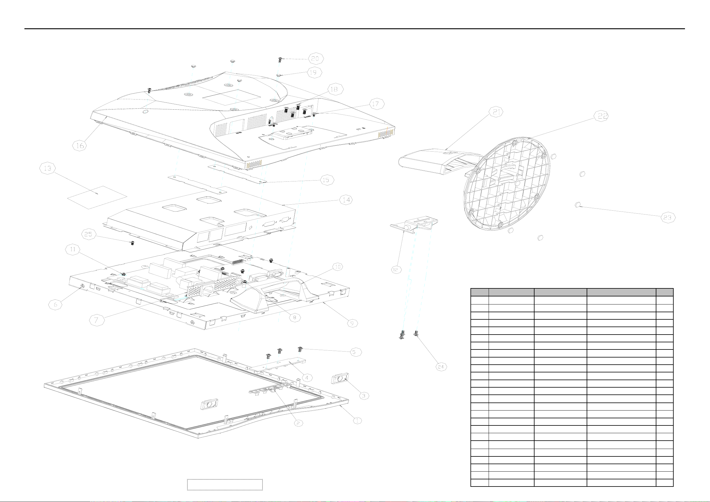
8. Exploded Diagram and Exploded Parts Lis0 t (VA703b-1)
ViewSonic Corporation
Confidential - Do Not Copy VA703b-1_VA703m-1
49
EXPLODED PARTS LIST (VA703b-1)
ViewSonic Model Number: VS11359
Rev: 1a
Serial No. Prefix: Q85
Item ViewSonic P/N Ref. P/N Description Q'ty
1 C-00006636 A34G0026B4Z L BEZEL 1
2 PL-00006485 33G5019 KD C FUNC.BUTTON 1
3 B-00005797 KEPC560KE1P KEPC BOARD 1
4 N/A Q1G 330 6120 SCREW 3
5 N/A J15G8313 1 AC SOCKET BRKT 1
6 N/A M1G 130 5120 SCREW 4
7 N/A M1G1730 6120 SCREW 7
8 M-00006643
9 C-00006488 A34G0029 4Z L HINGE COVER 1
10 N/A M1G 330 4120 SCREW 4
11 N/A Q1G1140 8120 SCREW 3
12 HW-00006644 37G 561 1 HINGE 1
13 N/A Q52G6025 11997 1
14 N/A J85G 740 1 3 MAIN SHIELD 1
15 N/A J15G0013 1 VESA PLATE 2
16 C-00006637 A34G0025 4Z 2L REAR COVER 1
17 N/A M1G 330 6 47 SCREW 2
18 N/A M1G2640 8 47 SCREW 4
19 N/A
20 N/A M1G 330 6 47 SCREW 2
21 PL-00006486
22 C-00006487 A34G0028 4Z L BASE 1
23 N/A J12G 394800 FOOT 6
J15G8312 1
J12G 808 2
A34G0027 4Z L
MAIN FRAME HYDIS 1
INSULATION SPACER
VESA RUBBER 4
STAND 1
Page 53
Exploded Diagram and Exploded Parts List (VA703m-1)
ViewSonic Corporation
0
Confidential - Do Not Copy VA703b-1_VA703m-1
5
EXPLODEDPARTSLIST(VA703m-1)
ViewSonicModelNumber:VS11359
Rev:1a
Serial No. Prefix: Q86
Item ViewSonicP/N Ref.P/N Description Q'ty
1 C-00006655 A34G0026AKDL BEZEL 1
2 PL-00006485 33G5019KDC FUNC.BUTTON 1
3 E-00006658 78G4553K SPEAKER,8OHM1.5W 2
4 B-00005824 KEPC560KD9P KEPCBOARD 1
5 N/A Q1G3306120 SCREW 3
6 N/A M1G1305120 SCREW 4
7 N/A J15G83131 ACSOCKETBRKT 1
8 N/A M1G17306120 SCREW 5
9 M-00006643
10 C-00006514 A34G0029KRL HINGECOVER 1
11 N/A M1G17306120 SCREW 4
12 HW-00006644 37G5611 HINGE 1
13 N/A Q52G602511997 1
14 N/A J85G74013 MAINSHIELD 1
15 N/A J15G00131 VESAPLATE 2
16 C-00006656 A34G0025KR1L REARCOVER 1
17 N/A M1G330647 SCREW 2
18 N/A M1G2640847 SCREW 4
19 N/A J12G8081 VESARUBBER 4
20 N/A M1G330647 SCREW 2
21 PL-00006512 A34G0027KRL STAND 1
22 C-00006513 A34G0028KRL BASE 1
23 N/A J12G394800 FOOT 6
24 N/A Q1G11408120 SCREW 3
25 N/A M1G3304120 SCREW 4
J15G83121
MAINFRAMEHYDIS 1
INSULATION SPACER
Page 54

Packing diagram (VA703b-1)
PACKING PART LIST (VA703b-1 )
ViewSonic Model Number: VS11359
Rev: 1a
Item ViewSonic P/N Ref. P/N Location Q'ty
1 P-00006649 J44G7003709 2A CARTON 1
2 N/A 50G 600 2/3 HANDLE1/2 1
3 P-00005642 45G 76 28 V3 PE BAG 1
4 DC-00006640 J70G170170913A CD MANUAL 1
5 DC-00005803 41G7801709 7A QSG 1
6 P-00005643 45G 88606 PE BAG FOR BASE 1
7 N/A T780KK5HKUVWNBP MONITOR 1
8 P-00005644 45G 88607 PE BAG 1
9 N/A J44G7003 1/2 EPS 1
10 A-00003716 89G402A18N LS POWER CORD 1
11 CB-00005795 89G 725HAA903 SIGNAL CABLE 1
12 C-00006487 A34G0028 4Z L BASE 1
1
5
ViewSonic Corporation Confidential - Do Not Copy VA703b-1_VA703m-1
Page 55

Packing diagram (VA703m-1)
PACKING PARTS LIST (VA703m-1)
ViewSonic Model Number: VS11359
Rev: 1a
Item ViewSonic P/N Ref. P/N Location Q'ty
1 N/A J44G7003709 2A CARTON 1
2 N/A 50G 600 2/3 HANDLE1/2 1
3 N/A 45G 76 28 V3 PE BAG 1
4 N/A J70G170170913A CD MANUAL 1
DC-00006496
5
6 N/A 45G 88606 PE BAG FOR BASE 1
7 N/A T780KK5HKUVWABP MONITOR 1
8 N/A 45G 88609 B EPE BAG 1
9 N/A 45G 88607 PE BAG 1
10
11 N/A 89G 173 56 31 AUDIO CABLE 1
12 N/A 89G402A18N LS POWER CORD 1
13 N/A 89G 725HAA903 SIGNAL CABLE 1
14
P-00006647
P-00006648
C-00006513
41G7801709 8A QSG 1
J44G7003 1 EPS 1
J44G7003 2 EPS 1
A34G0028 KR L BASE 1
2
5
ViewSonic Corporation Confidential - Do Not Copy VA703b-1_VA703m-1
Page 56

9. Block Diagram
ViewSonic Corporation Confidential - Do Not Copy VA703b-1_VA703m-1
53
Page 57

10. Schematic Diagrams
TSUM16AK SCHEMATIC
+5V
B3
+5V
3.INPUT
RIN
GNDR
GIN
GNDG
SOG
BIN
GNDB
HSYNC
VSYNC
DDCA_SDA
DDCA_SCL
DET_VGA
DDC_WP
CLK+
CLK-
DDCD_SDA
DDCD_SCL
DET_DVI
R+
G+
R-
GB+
XGA/SXGA LVDS OUTPUT
B4
RIN
GNDR
GIN
GNDG
SOG
BIN
GNDB
HSYNC
VSYNC
DDCA_SDA
DDCA_SCL
DET_VGA
DDC_WP
R+
R-
G+
G-
B-
B+
B-
CLK+
CLKDDCD_SDA
DDCD_SCL
DET_DVI
VCC1.8
Vcc3.3
+5V
+12V
VCC1.8
VCC3.3
+5V
+12V
VCC3.3
VCC5V
+5V
VCC1.8
+3V3
PC5V
+12V
B2
+12V
+3V3
VCC1.8
Adj_BACKLIGHT
+5V
VCC5V
VCC3.3
2.POWER
on_BACKLIGHT
on_Panel
on_PANEL_12V
VCTRLPC5V
VLCD
VLCD_12V
VLCD
VLCD_12V
on_BACKLIGHT
on_Panel
on_PANEL_12V
VCTRL
Adj_BACKLIGHT
4.SCALER
PA[0..7]
PA[8..13]
PA[14..19]
PB[0..5]
PB[6..11]
PB[12..23]
GPO[0..4]
ESP
OSP
PA[0..7]
PA[8..13]
PA[14..19]
PB[0..5]
PB[6..11]
PB[12..23]
GPO[0..4]
B5
PA[0..7]
PA[8..13]
PA[14..19]
PB[0..5]
PB[6..11]
PB[12..23]
GPO[0..4]
ESP
OSP
VLCD
VLCD_12V
5.PANEL INTERFACE
ViewSonic Corporation
Model
Title
TOP
VLCD_12VVLCD
ViewSonic Corporation Confidential - Do Not Copy VA703b-1_VA703m-1
54
Date Rev:
Page 58

C706
0.1uF
+5V3,4
Adj_BACKLIGHT
NC
on_Panel4
R716
+5V
C707
100uF/25V
C709
0.1uF
+3V3
C701
NC
+
R717
10K 1/16W
4.7K 1/16W
+12V
+5V
C710
+
100uF/25V
R725
C718
0.1uF
U701
NC/LT1117-18
3 2
BL_ADJ(DC)
0V ~ 3.3V 4.7K
0V ~ 5V
BL_ADJ
P W M
+12V 4
GND
GND
+12V
GND
+5V
GND
11
R706
NC
R707
4.7K 1/16W
+5V
R714
10K 1/16W
SOT-223
VI VO
CN701
1
3
5
7
9
CONN
4
VO
GND
1
R31
4.7K
R31
47
4K7D C
2
4
6
8
10
12
VCC5V
Q701
R723 51K 1/16W
Q706
PMBS3904
C703
100uF/25V
C51
1UF
C32
N.C
1uF
BL_ON
BL_ADJ
+12V
GND
+5V
GND
R701
1K 1/16W
R705
PMBS3904
+3V3
R715
NC
C715
0.1uF
+
R29
R32
01UF
X
X
1K
4.7K 1/16W
VLCD
Q704
AO3401L
+
C717
10uF/16V
C708
1uF
R33
X
4.7K
C711
0.1uF
C704
NC
Q4
X
MMBT3904
+5V
R708
10K 1/16W
VLCD 5
+5V
+3V3
Q703
PMBS3904
R721
0 1/16W
R727
10K 1/16W
+3V3
R710 NC
R712 4.7K 1/16W
P.S: The 1N4148 Vf=0.7V~1V can't meet
LDO spec. The BAT42, Vf is OK but the
If=200mA(forward current) can not
meet current spec.
For RSDS and Panel VCC=12V
+3V3
R722
NC
on_Panel_12V4
H2
678
9
123
123
5
678
5
4
4
TP
9
9
+5V
H1
678
678
9
5
4
123
TP
123
R711
10K 1/16W
5
4
D704(SSM12L) Vf=0.38V and If=1A.
So when system power on, the
system loading is about 400mA
(3.3V is about 200mA and 1.8V is
about 200mA), So D35 changed
from 1N4148(or BAT42) to
SSM12L(schottky diode).
+5V
R718
NC/10K
R726 NC/4K7
+5V
C720
NC/0.1uF
R729
NC/10K
+12V
R719
NC/10K
R724 51K
Q707
PMBS3904
C716
0.1uF
H3
9
9
123
123
VLCD_12V
Q705
AO3401L
+
C719
NC/10uF/16V
678
5
678
5
4
4
TP
+5V3,4
VLCD_12V 5
+5V3,4on_BACKLIGHT 4
D704
SMAL140
R728
NC/4K7
+5V
R732
10 1/16W
+5V
C705
1uF/16V
+5V
2
3
C713
0.1uF
R730
0 1/16W
PC5V
1
+12V
+
R709
0 1/16W
D703
BAT54C
R731
NC
VCTRL 4
R702
51 1/16W
VCC1.8
VCC3.3
B
D702
1N4148
R704
100 1/16W
C
Q702
CHT2907
E
D701
1N4148
+
C702
4.7uF/16V
R703
2K 1/16W
Recommond to used "Blue" parts circuit
for VCC1.8V if you want to suppoert DDC
PC5V 3
function when system power off
TO-263
U702
3
VIN
1
ADJ
AIC1084-33PM
2
VOUT
4
VOUT
R720 0 1/16W
R713
NC
C712
+
100uF/25V
C714
0.1uF
12/21 MODIFY
ViewSonic Corporation
VCC1.8 4
VCC3.3 4
VCC3.3
VCC3.3 4
ViewSonic Corporation Confidential - Do Not Copy VA703b-1_VA703m-1
55
Model
Title
POWER
Date Rev:
Page 59

CN405
1716
DB15
RED+
11
12
13
14
15
1
RED-
6
GREEN+
2
GREEN-
7
BLUE+
3
BLUE-
8
4
9
VGA_CON
5
10
MLL5232B 5.6V
PC5V
D406
PC5V
3
C439 0.1uF
2
D403
BAV99
1
3
D404
BAV99
C440 0.1uF
2
1
FB410 0 1/16W
FB411 0 1/16W
FB412 0 1/16W
3
D405
BAV99
ESD_5V
C441 0.1uF
1
2
R438
75 1/16W
R439
75 1/16W
R440
75 1/16W
R434 56 1/16W
R435 56 1/16W
R436 56 1/16W
R437 470 1/16W
R441 100 1/16W
R442 100 1/16W
R443 100 1/16W
+5V
R444
10K 1/16W
+5V 2,4
C432 0.047uF
C433 0.047uF
C434 0.047uF
C435 0.047uF
C436 0.047uF
C437 0.047uF
C438 0.047uF
RIN 4
GIN 4
BIN 4
SOG 4
GNDR 4
GNDG 4
GNDB 4
CN406
RGB GND
HSYNC
VSYNC
SYNC GND
DDC SCL
DDC SDA
1/3shield
2/4shield
0/5shield
clk shield
DAT0+
DAT1+
DAT2+
DAT3+
DAT4+
DAT5+
JACK DVI
HSI
VSI
D408
MLL5232B 5.6V
25
R
26
G
27
B
29
28
8
15
6
7
14
+5V
16
HPD
11
3
19
22
18
17
DAT0-
10
9
DAT1-
2
1
DAT2-
13
12
DAT3-
5
4
DAT4-
21
20
DAT5-
23
clk+
24
clk-
SCL_DVI
SDA_DVI
DVI5V
HPD
DAT0+
DAT0DAT1+
DAT1DAT2+
DAT2-
DCLK+
DCLK-
2
FB409 120 OHM
D409
MLL5232B 5.6V
VCC5V
R472
NC
3
C447
0.1uF
D417
BAV99
3
C448
1
2
0.1uF
R471
10K 1/16W
R458 100 1/16W
D426
LL5232B 5.6V 5%
D418
BAV99
2
1
3
C449
0.1uF
D419
BAV99
1
R448
2.2K 1/16W
DET_DVI 4
D414
LL5232B 5.6V 5%
3
D420
BAV99
C450
1
2
0.1uF
3
C451
2
0.1uF
R446 1K 1/16W
C442
33pF
D415
LL5232B 5.6V 5%
D421
BAV99
1
R449
2.2K 1/16W
R455 100 1/16W
R456 100 1/16W
2
3
C452
0.1uF
D422
BAV99
1
R447 1K 1/16W
C443
220pF
D416
LL5232B 5.6V 5%
3
D423
BAV99
C453
1
2
0.1uF
D411
MLL5232B 5.6V
DVI5V
R457
C445
0.1uF
R462 10 1/16W
R463 10 1/16W
R464 10 1/16W
R465 10 1/16W
R466 10 1/16W
R467 10 1/16W
R468 10 1/16W
R469 10 1/16W
3
D424
BAV99
C454
1
2
0.1uF
R445 100 1/16W
D410
MLL5232B 5.6V
D412
MLL5232B 5.6V
10K 1/16W
ESD_5V
B+ 4
B- 4
G+ 4
G- 4
R+ 4
R- 4
CLK+ 4
CLK- 4
SCL_VGA
SDA_VGA
+5V
1 2
R470
1K 1/16W
D425
RLZ36B
DET_VGA 4
HSYNC 4
VSYNC 4
R450
10K 1/16W
R453 100 1/16W
R454 100 1/16W
DDCA_SDA4
DDCA_SCL4
DDCD_SDA4
DDCD_SCL4
10K 1/16W
10K 1/16W
R459
+5V
R451
R452
10K 1/16W
R460
10K 1/16W
10K 1/16W
2
+5V
R461
PC5V
1
D407
BAV70
3
U404
8
VCC
7
WP
6
SCL
M24C02
DVI5V
3
R473
NC
1
D413
BAV70
U405
8
7
6
M24C02
VCC
WP
SCL
2
1
A0
2
A1
3
A2
45
GNDSDA
A0
A1
A2
GNDSDA
C444
0.1uF
DDC_WP 4
1
2
3
45
C446
0.1uF
DDC_WP 4
ViewSonic Corporation
Model
Title
Date Rev:
INPUT
ViewSonic Corporation Confidential - Do Not Copy VA703b-1_VA703m-1
56
Page 60

DDCA_SDA3
DDCA_SCL3
VCC3.3
+
C418
10uF/16V NC
R404
10K 1/16W NC
+5V
Reset
Circuit
C417
0.1uF
R489
10K 1/16W
R486
NC
U406
GND
1
VCC3.3
R490
10K 1/16W
VCC3.3
R487
10K 1/16W
23
RSTVCC
ASM810MEURF-T
Volume
RIN3
GNDR3
GIN3
GNDG3
SOG3
BIN3
GNDB3
HSYNC3
VSYNC3
R+3
R-3
G+3
G-3
B+3
B-3
CLK+3
DDCD_SDA3
DDCD_SCL3
AVDD
R403 390 1%
U402
8
SDO
VDD
7
3
4 5
HOLD#
WP#
VSS SDI
WP
VCC3.3
R407 NC
R410 NC
CE#
SCK
SST25VF010-20-4C-SAE
C421 22pF
14.318MHz
C423 22pF
R415
10K 1/16W
R431 0 1/16W
R433 NC
VMPLL
VDVI
44
RIN0P
AVDD_DVI
RIN0N
GIN0P
GIN0N
SOGIN0
BIN0P
BIN0N
HSYNC0
VSYNC0
DDCA_SDA
DDCA_SCL
RX2P
RX2N
RX1P
RX1N
RX0P
RX0N
RXCKP
RXCKN
DDCD_SDA
DDCD_SCL
REXT
REFP
REFM
SDO
SCZ
SCK
SDI
RST
XIN
XOUT
MODE[0]
MODE[1]
R430
1K 1/16W
R432 0 1/16W
PMBS3904
50
AVDD_DVI
U401
59
58
56
55
57
54
53
63
64
65
66
39
40
42
43
45
46
48
49
36
37
51
62
C401
61
0.1uF
70
2
71
1
72
6
73
19
X401
32
33
102
104
R416
10K 1/16W
+5V
Q404
VPLL
52
34
4
AVDD_MPLL
AVDD_MPLL
TSUM16AK
RSDS/LVDS/TTL
GND
3896116
13
AVDD
14
60
AVDD_PLL
AVDD_ADC
GND
GND
GND
GND
41
47
C431
NC
67
VDDP
GND
VDDP
95
VDDP
OUT-L+
OUT-L-
VDDP
103
VDDP
VDDC
12
68
97
115
117
VDDP
VDDC
VDDC
VDDC
NC/LVACKP/NC
NC/LVACKM/NC
VDD_OTP
RA1P/LVA2P/RA2
RA1N/LVA2M/RA3
RA2P/LVA1P/RA4
RA2N/LVA1M/RA5
RA3P/LVA0P/RA6
RA3N/LVA0M/RA7
GA3P/LVA3P/GA6
GA3N/LVA3M/GA7
CLKAP/LVB3P/LHSYNC
CLKAN/LVB3M/LVSYNC
CLKBP/LVBCKP/LCK_ODD
CLKBN/LVBCKM/LDE
BB1P/LVB1P/BB2
BB1N/LVB1M/BB3
BB2P/LVB0P/BB4
BB2N/LVB0M/BB5
PWM2/GPIO_P24
GPIO_P27/PWM1
PWM1/GPIO_P25
GPIO_P17/SAR0
GPIO_P00/SAR1
GPIO_P01/SAR2
GPIO_P02/SAR3
PWM0/GPIO_P26
DDCROM_SCL
DDCROM_SDA
FB407
600 OHM
FB408
600 OHM
CN404
1
3
5
7
9
11
13
CONN
VCTRL
GA1P/NC/GA2
GA1N/NC/GA3
GA2P/NC/GA4
GA2N/NC/GA5
BA1P/NC/BA2
BA1N/NC/BA3
BA2P/NC/BA4
BA2N/NC/BA5
BA3P/NC/BA6
BA3N/NC/BA7
RB1P/NC/RB2
RB1N/NC/RB3
RB2P/NC/RB4
RB2N/NC/RB5
RB3P/NC/RB6
RB3N/NC/RB7
GB1P/NC/GB2
GB1N/NC/GB3
GB2P/NC/GB4
GB2N/NC/GB5
GB3P/NC/GB6
GB3N/NC/GB7
NC/LVB2P/NC
NC/LVB2M/NC
BB3P/NC/BB6
BB3N/NC/BB7
GPIO_P22
GPIO_P23
GPIO_P03
GPIO_P16
GPIO_P15
GPIO_P16
GPIO_P06
GPIO_P07
GPIO_P13
GPIO_P14
GPO0
GPO1
GPO2
GPO3
GPO4
GPO5
GPO6
2
4
6
8
10
12
14
OSP
FB401
600 OHM
600 OHM
R474
1 2
4.7uF/16V
FB403
R413
VCC3.3
D402
C403
RLZ36B
VDDC
+
VCC3.3
VCC3.3
3.9K 1/16W
C404
0.1uF
C408
10uF/16V
VCC3.3
Q401
R475
600 OHM
FB406
600 OHM
R414
120 1/16W
PMBS3906
C405
C406
0.1uF
0.1uF
VDDP
+
C409
0.1uF
VDVI
FB404
C414
0.1uF
VMPLL
C419
0.1uF
R421 0 1/16W
FB402
VCC3.3
C411
C410
0.1uF
0.1uF
C415
0.1uF
C420
0.1uF
10K 1/16W
LED_G
R476 1K 1/16W
R477 1K 1/16W
C412
0.1uF
R408
VCC3.32
C413
0.1uF
R478 1K 1/16W
VCC3.32
VCC3.3
R479 1K 1/16W
600 OHM
R409
120 1/16W
Q403
PMBS3906
R419 0 1/16W
R480 1.5K 1/16W
VCC3.3
ViewSonic Corporation
Model
Title
SCALER
AVDD
FB405
600 OHM
LED_A
KEY_AUTO
KEY_RIGHT
KEY_MENU
KEY_LEFT
C407
0.1uF
VPLL
C416
0.1uF
KEY_A
KEY_B
KEY_C
VCC1.8
VCC1.82
11
PA0
107
PA1
108
PA2
109
PA3
110
PA4
111
PA5
112
PA6
113
PA7
114
PA8
98
PA9
99
PA10
100
PA11
101
PA12
105
PA13
106
PA14
89
PA15
90
PA16
91
PA17
92
PA18
93
PA19
94
PB0
9
PB1
10
PB2
15
PB3
16
PB4
17
PB5
18
PB6
2
PB7
3
PB8
5
PB9
6
PB10
7
PB11
8
PB12
118
PB13
119
PB14
120
PB15
121
PB16
122
PB17
123
PB18
124
PB19
125
PB20
126
PB21
127
128
PB22
PB23
1
ESP
80
ESP
81
88
87
86
85
84
83
82
75
74
26
35
69
78
79
20
21
22
23
R418 100 1/16W
24
R420 100 1/16W
25
R411 100 1/16W
27
R422 4.7K 1/16W
28
R423 4.7K 1/16W
29
30
31
77
76
10K 1/16W
+12V
+5V
10K 1/16W
OUT-R+
OUT-R-
OSP
GPO0
GPO1
GPO2
GPO3
GPO4
R488 NC
VCC3.3
R424
+12V 2
+5V 2,3
R484
R425
10K 1/16W
+5V
VCTRL 2
PB[12..23]
WP
AUDIO_MUTE
AUDIO_STBY
R426
AUDIO_STBY
AUDIO_MUTE
10K 1/16W
R427 100 1/16W
R428 100 1/16W
R429 100 1/16W
R485
10K 1/16W
P[0..7]
PA[8..13]
PA[14..19]
PB[0..5]
PB[6..11]
GPO[0..4]
KEY1
KEY2
POWER
Volume
Option
PA[0..7] 5
PA[8..13] 5CLK-3
PA[14..19] 5
PB[0..5] 5
PB[6..11] 5
PB[12..23] 5
ESP 5
OSP 5
GPO[0..4] 5
R405
22K 1/16W
10K 1/16W
on_PANEL_12V 2
DET_DVI 3
DET_VGA 3
on_PANEL 2
on_BACKLIGHT 2
adj_BACKLIGHT 2
U403
8
VCC
7
WP
6
SCL
AT24C16N-10SC-2.7
KEY_B
LED_G
KEY_AUTO
KEY_RIGHT
POWER
OUT-L+
OUT-L-
R406
VCC3.3
VCC3.32
VCC3.32
VCC3.32
GND
DDC_WP 3
R481
NC
B
KEY_A
LED_A
KEY_MENU
KEY_LEFT
KEY_C
OUT-R+
OUT-R-
VCC3.3
C
E
Q405
R482
NC
NC
R483
NC
KEY2
KEY1
LED_G
LED_A
POWER
C426
0.1uF
C427
0.1uF
C428
0.1uF
KEY A
C616
NC
C429
0.1uF
+5V
R412
10K 1/16W
R417 20K 1/16W
C424 0.1uF
3.9K 1/16W
C430
D401
0.1uF
RLZ36B
1 2
+5V 2,3
10K 1/16W
Q402
PMBS3904
C422
0.1uF
C425
0.1uF
1
A0
2
A1
3
A2
45
GNDSDA
CN403
CONN
2
4
6
8
10
12
14
16
1
3
5
7
9
11
13
15
ViewSonic Corporation Confidential - Do Not Copy VA703b-1_VA703m-1
57
Date Rev:
Page 61
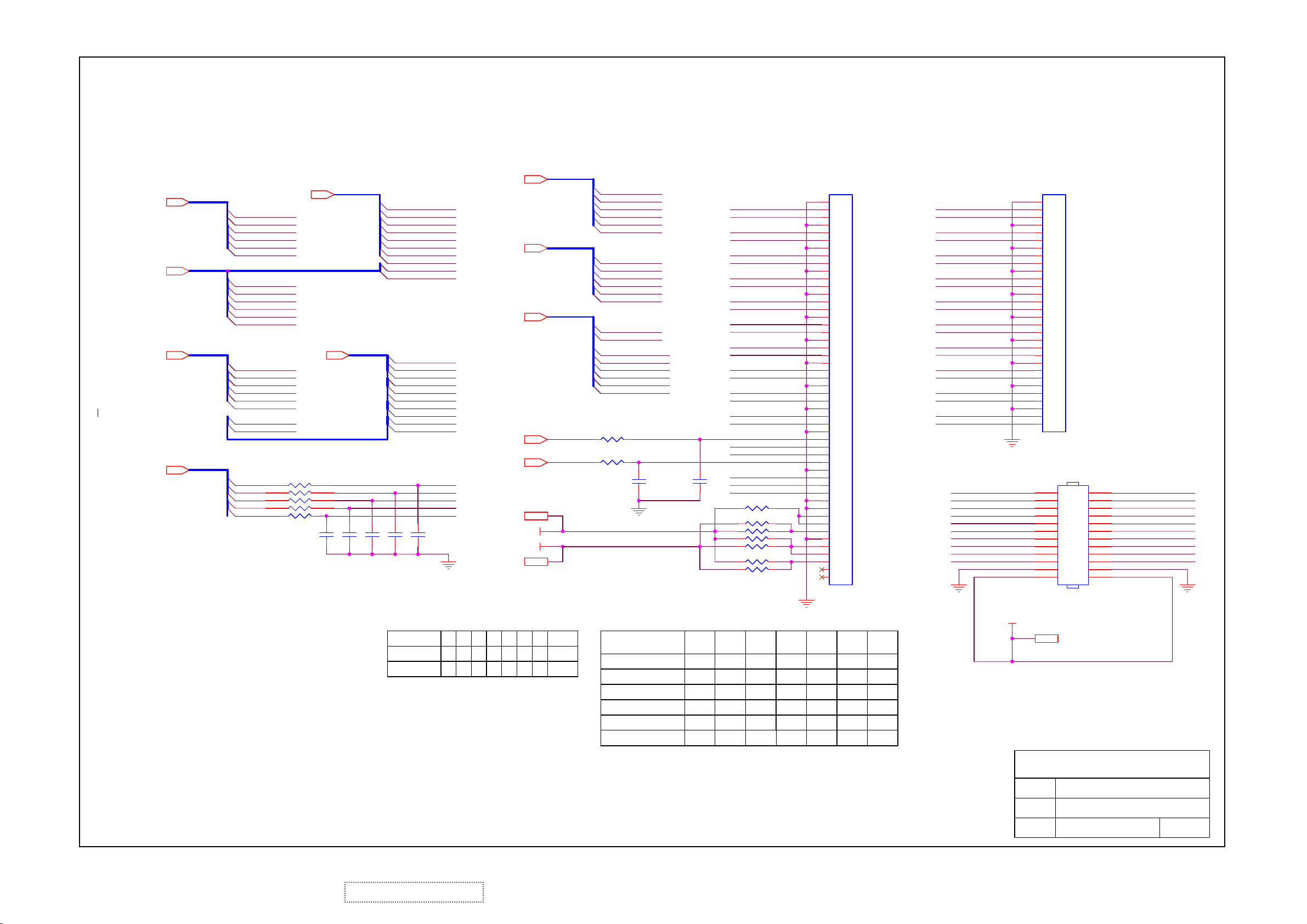
PB[0..5]4
8
7
6
C101
NC
PA[0..7]
PB[12..23]
C102
NC
PA0
LVACKP
PA1
LVACKM
PA2
LVA2P
PA3
LVA2M
LVA1P
PA4
PA5
LVA1M
PA6
LVA0P
PA7
LVA0M
PA12
LVA3P
PA13
LVA3M
PB12
LVB3P
PB13
LVB3M
PB14
LVBCKP
LVBCKM
PB15
PB16
LVB2P
PB17
LVB2M
PB18
LVB1P
LVB1M
PB19
PB20
LVB0P
PB21
LVB0M
GPOO0
GPOO1
GPOO2
GPOO3
GPOO4
C103
NC
C105
C104
NC
NC
CN7
CN8
LVDS Panel
RSDS Panel V
X
V
PB[6..11]4
PB[12..23]4
OSP4
ESP4
VLCD2
VLCD RXE1+
VLCD_12V
VLCD_12V2
R88
RP1
CN9
X
V
V
X
R89
X
X
V
V
PA[0..7]4
PA[8..13]4
PA[14..19]4
GPO[0..4]4
PA[0..7]
PA[8..13]
GPO[0..4]
PA2
PA3
PA4
PA5
PA6
PA7
PA8
PA9
PA11
PA12
PA13
PA14
PA15
PA16
PA17
PA18
PA19
PB12
PB13
GPO0
GPO1
GPO2
GPO3
GPO4
PA[0..7]4
RA1P
RA1N
RA2P
RA2N
RA3P
RA3N
GA1P
GA1N
GA2PPA10
GA2N
GA3P
GA3N
PB[12..23]4
BA1P
BA1N
BA2P
BA2N
BA3P
BA3N
CLKAP
CLKAN
RP101 NC
1
2
3
4 5
R110 NC
PB[0..5]
PB0
RB1P
PB1
RB1N
PB2
RB2P
PB3
RB2N
PB4
RB3P
PB5
RB3N
PB[6..11]
PB6
GB1P
PB7
GB1N
PB8
GB2P
PB9
GB2N
PB10
GB3P
PB11
GB3N
PB[12..23]
CLKBP
PB14
CLKBN
PB15
BB1P
PB18
BB1N
PB19
BB2P
PB20
BB2N
PB21
BB3P
PB22
BB3N
PB23
OSP
R101 NC/0
R102 NC/0
ESP
C106
NC
R91
Table 1
X
X
X
V
Table 1
AU 17
QDI 17
CPT 17
INNOLUX 15
HannStar 15
CPT 15
LG 15
Innolux 17"
R90
NC
3.3V
0R
3.3V
0R
3.3V
0R 0R
3.3V
0R
NC
RA3N
RA3P
RA2N
RA2P
RA1N
RA1P
GA3N
GA3P
GA2N
GA2P
GA1N
GA1P
CLKAN
CLKAP
BA3N
BA3P
BA2N
BA2P
BA1N
BA1P
GPOO1
GPOO0
C107
GPOO3
GPOO2
GPOO4
NC
R103 NC
R104 NC
R105 NC
R106 NC
R107 NC
R108 NC
R109 NC
R92
NC
12V
0R
NC
NC
NC
NC
R93
3.3V
3.3V
3.3V
3.3V
FB0N
FB0P
FB1N
FB1P
FB2N
FB2P
FG0N
FG0P
FG1N
FG1P
FG2N
FG2P
FCLKN
FCLKP
FR0N
FR0P
FR1N
FR1P
FR2N
FR2P
STH
LP
POL
STV2
CLKV
STV1
OE
R94
5V
5V
0R
0R
NC
NC
0R
NC
NC
0R
NC
3.3V
0R
0R
CN102
1
2
3
4
5
6
7
8
9
10
11
12
13
14
15
16
17
18
19
20
21
22
23
24
25
26
27
28
29
30
31
32
33
34
35
36
37
38
39
40
41
42
43
44
45
46
47
48
49
50
IL-FHR-B50S-HF (JAE)
R96
R95
5V
NC
0RV
12V
0R
NC
NC
NC
12V
NC
0R
NC
NC
3.3V
NC
0R
R97
NC
12V
0R
NC
NC
NC
NC
RB3N
RB3P
RB2N
RB2P
RB1N
RB1P
GB3N
GB3P
GB2N
GB2P
GB1N
GB1P
CLKBN
CLKBP
BB3N
BB3P
BB2N
BB2N
BB2P
BB1N
BB1P
B0N
B0P
B1N
B1P
B2N
B2P
BG0N
BG0P
BG1N
BG1P
BG2N
BG2P
BCLKN
BCLKP
BR0N
BR0P
BR1N
BR1P
BR2N
BR2P
LVB0M
LVB1M
LVB2M
LVBCKM
LVB3M
LVA0M
LVA1M
LVA2M
LVACKM
LVA3M
RXO0-
RXO2RXOCRXO3RXE0RXE1RXE2RXECRXE3-
VLCD
CN103
1
2
3
4
5
6
7
8
9
10
11
12
13
14
15
16
17
18
19
20
21
22
23
24
25
26
27
28
29
30
IL-FHR-B30S-HF (JAE)
CN101
1
3
5
7
9
11
13
15
17
19
21
23
CONN
VLCD 2
2
4
6
8
10
12
14
16
18
20
22
24
RXO0+
RXO1+
RXO2+
RXOC+
RXO3+
RXE0+
RXE2+
RXEC+
RXE3+
LVB0P
LVB1PRXO1LVB2P
LVBCKP
LVB3P
LVA0P
LVA1P
LVA2P
LVACKP
LVA3P
ViewSonic Corporation Confidential - Do Not Copy VA703b-1_VA703m-1
58
ViewSonic Corporation
Model
Title
Date Rev:
PANEL INTERFACE
Page 62

+12V
ON/OF F
+5V
DIM
RJ801
0 1/8W
R803
10K 1/10 W
N.C R806
470 1/8W
N.C R838
0 1/8W
R808
RJ802
0 1/8W
RJ803
0 1/10W
RJ804
0 1/8W
C828,C829
R802
300K 1/8W
Q801
PMBS3904
1
N.C C801
0.1uF /50V
32
R804
10K 1/8W
32
Q802
1
PMBS3904
ZD801
RLZ5.6B
R809
R805
470 1/8W
Q803
PMBS3904
N.C C828
0.1uF/50V
AM9945
Q805
R818
15 1/ 8W
C812
N.C R839
1500PF/ 50V
33K 1/8W
6
8
D1N7D1N
S1N1G1N2S2P3G2P
1000P/50V
D2P5D2P
4
N.C C814
R819
15 1/ 8W
C813
1500PF/ 50V
C811
VCC
R807
22 1/8W
+
470UF /25V
32
1
PT801
80GL19T-8-DN
5
3
4
1 8
R820
15K 1/10W
C830
100PF/ 50V
1
3
7
2
D801
BAV70
R821
100K 1/10W
C831
100PF/ 50V
C816
12PF/3K V
C817
5PF/ 3KV
C818
470PF/ 50V
N.C R823
75K 1/10W
R822
3M / 1/2W
R827
3.6K 1/ 10W
CN801
R836
1K 1/10W
3
D802
BAV99
R825
560 1/10W
2
1
2
1
33G8021-2D-U
CN802
2
1
33G8021-2D-U
470K 1/8W
J811
TIN COATED
J812
TIN COATED
J818
TIN COATED
J823
TIN COATED
C803
0.01U F/50V
J814
TIN COATED
J819
TIN COATED
R811
150K 1/ 10W
R812
10K 1/10W
C804
2.2uF/ 25V
J815
TIN COATED
J820
TIN COATED
1M 1/10W
J816
TIN COATED
J821
TIN COATED
C805
1000PF/ 50V
R810
R813
1M 1/ 10W
J817
TIN COATED
J822
TIN COATED
C806
56K 1/ 10W
C820
1UF/25V
R842
10 1/10W
C834
100PF/ 50V
+
N.C C829
0.1uF /50V
IC801
1
DRV1
2
VDDA
3
TIME R
4
DIM
5
ISEN
6
VSEN
7
OVPT
NC18NC2
OZ9938
C822
1500PF/ 50V
33K 1/8W
PGND
DRV2
GNDA
SSTCMP
R828
15 1/ 8W
N.C R840
8
S1N1G1N2S2P3G2P
LCT
ENA
CT
1000P/
D1N7D1N
16
10 1/10 W
15
14
13
12
11
10
9
N.C C815
6
4
R837
D2P5D2P
R829
15 1/ 8W
C823
1500PF/ 50V
Q806
AM9945
R815
100K 1/ 10W
C807
0.01UF/ 50V
5
3
4
1 8
R816
R817
1M 1/ 10W
C809
C808
6800PF/ 50V
PT802
80GL19T-8-DN
R830
15K 1/10W
C832
100PF/ 50V
1
100K 1/ 10W
R814
470UF /25V
39K 1/ 10W
0.047U F/50V
7
2
N.C R844
39K 1/10W
C810
470PF/ 50V
R831
100K 1/10W
R841
R826
C819
0.047U F/25V
360 1/ 10W 1%
390 1/ 10W 1%
1Mohm brust frequency:400HZ
C825
12PF/3K V
C826
5PF/ 3KV
R832
3M / 1/2W
C827
470PF/ 50V
CN803
R843
1K 1/10W
3
D804
BAV99
R835
560 1/10 W
2
1
1
2
33G8021-2D-U
CN804
1
2
33G8021-2D-U
ViewSonic Corporation Confidential - Do Not Copy VA703b-1_VA703m-1
59
3
D803
BAV70
C833
100PF/ 50V
75K 1/10 W
N.C R833
R834
3.6K 1/ 10W
ViewSonic Corporation
Model
Title
Date Rev:
INVERTER
Page 63

R951
3
R900
330K 1/8W
1
+
BD901
2A 600V
2
-
4
2
3
L902
L
穝
1
4
0.001uF /250V
0.001uF /250V
2
3
L901
L
1
4
C909 0. 47uF/250V
R901
330K 1/8W
R902
330K 1/8W
3
12
CN 901
SOCKET
C902
C901
12
t
F901
2.5A/250V
NR901
NTCR
0.1uF /50V
GND1
1
GND
HS3 D920
1
2
HEAT SINK
+
C907
100uF/ 450V
C912
C916
0.1uF/50V
IC901
LD7575
7
R911
100K 1/10W
穝
1000PF/ 25V
GND2
1
GND
HS4 Q900
1
2
HEAT SINK
R905
10K 1/8W
8
HV
LD7575
N.C
OUT
RT1CS
GND
4
2
C914
R952
47 1/8W
R953
47 1/8W
47 1/8W (NC)
T90 1
4
O
12
2
O
1
43
IC921
KIA431
11
O
10
86
7
O
9
12
R954
47 1/8W
R955
47 1/8W
R956
47 1/8W(NC)
3A/60V
R909
1
3 2
1 Q910
100K 2W
D900
BA159GPT
R910
5R1 1/ 8W
Q900
STP9NK60Z PF
R916
0.43 2W
PMBS3906(NC )
3 2
C900
0.0022uF /250V
IC 902
PC123F Y 2 4P
C910
1500pF/ 1KV
D901
UF 4003PT
+
C911
D910
LL4148WP
R912
10 1/ 8W
10K 1/ 10W
R913
1K 1/ 10W
C915
22uF/ 50V
R915
D911
LL4148WP(NC)
0.1UF /25V(NC )
N.C ZD901
RLZ27B(NC)
1 2
6
VCC
5
3
COMP
C913
220pF/ 50V
C920
0.001uF /500V
D920
3
STPS20H100CT
2
1
3
2
D921
FMW-2156
1
D922
C921
0.001uF /500V
R922
470 1/ 4W
R925
1K 1/ 10W
C928
0.1uF /50V
R928
1K 1/ 4W
+
C922
680uF/ 25V
ZD 921
RLZ13B
1 2
D915
LL4148WP
R927
100 1/ 10W
蔼跋
+
C926
1000uF/ 16V
ZD922
RLZ5.1B
1 2
D916
+
C923
680uF/ 25V
+
C932
1000uF/ 16V(N C)
LL4148WP
R923
10K 1/ 10W
C929
0.1uF/50V
100 1/10W
19mm,
L921
+
C924
680uF/ 25V
R930
RJ901
0 1/8W
ㄏノ
13x16size
3.5U H
+
470UF /25V
L922
3.5UH
R924
3.6K 1/ 10W 1%
R929
2.4K 1/ 10W 1%
C925
+
C927
470UF /25V
R926
33K 1/ 10W 1%
RJ902
0 1/ 8W
R931
10K 1/8W
CN 902
CONNECTOR
1
2
3
4
5
6
7
8
9
10
F902
0 1/ 8W
PTZ9.1 B
1 2
C931
0.1uF /50V
+12V
ZD920
F903
0 1/ 8W
ON/OFF
+5V
C930
0.1uF /50V
audio 12V
DIM
ViewSonic Corporation
Model
+5V
J901
TIN COATED
J902
TIN COATED
J903
TIN COATED
J904
TIN COATED
J905
TIN COATED
J906
TIN COATED
J907
TIN COATED
J908
TIN COATED
J909
TIN COATED
J910
TIN COATED
J911
TIN COATED
ViewSonic Corporation Confidential - Do Not Copy VA703b-1_VA703m-1
60
Title
A-D POWER
Date Rev:
Page 64

12V
CN202
pin header2*7 2mm f emale
OUT_L
+12V
MUTE
NC
CN201
PHONEJACK
CN204
13
11
9
7
3
2
1
GND
VOLUME
GND
1
5
4
3
2
GND
R201
R203 18K 1/16W
C211
100pF
18K 1/16W
R210
20K 1/ 16W
R211
20K 1/ 16W
200
C212
100pF
R212
+
C209
1.0uF
C204 0.47uF/25V
C206 0.47uF/25V
+
C210
1.0uF
5
3
1
STANDBY
4
9
6
11
12
C213
0.1uF
14
12
10
8
6
4
2
INL
INR
VOLUME
STBY
MU TE
GND
123
+
C201
680uF/25V
U201
SVR
TDA7496L
17
14
10
7
5
C208
8
NC
GND
15
16
VS
VAROUT_R
VAROU T_L
GND
GND
GND
13
181920
VS
OUTL
OUTR
GND
GND
+
C202
680uF/25V
R207
+
470uF/16V
GND
1K
C203
0.1uF
OUT_R
C205
+
470uF/16V
+
470uF/16V
C207
R208
1K
GND
61
ViewSonic Corporation Confidential - Do Not Copy VA703b-1_VA703m-1
GND
GND GND
ViewSonic Corporation
Model
Title
Date Rev:
Audio
Page 65
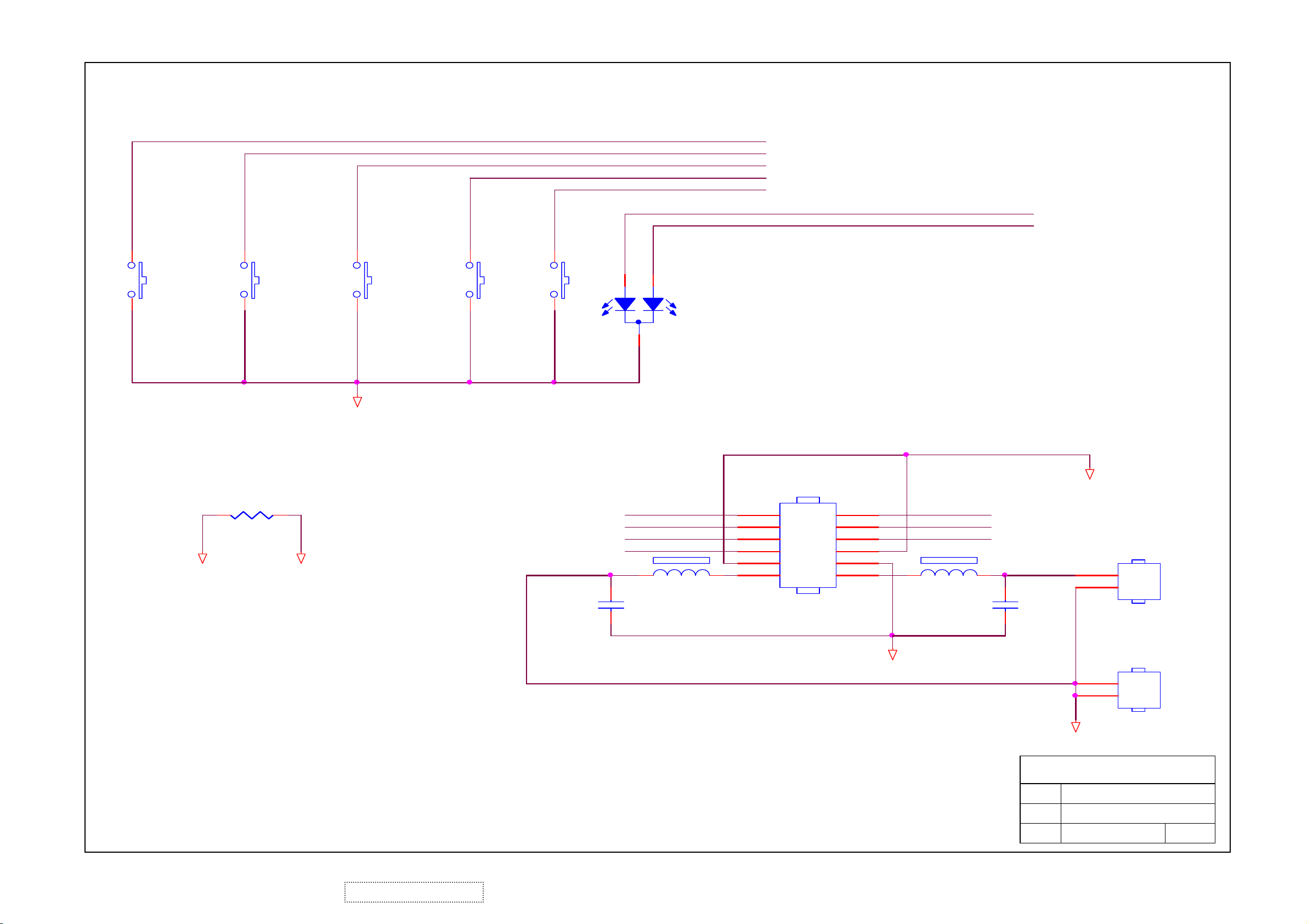
KEY_MENU
KEY_AUTO
POWER_KEY
KEY_LEFT
KEY_RIGHT
LED_Y
LED_G
KEY_MENU
SW1
SW2
KEY_AUTO
R003
0 1/16W
A_GND
POWER_KEY
GND
SW3
SW4
KEY_LEFT
SPKR_L+
SW5
1
3
2
KEY_RI GHT
LED_G
KEY_AUTO
KEY_RIGHT
POWER_KEY
C01
DP1
LED
FB01
120 OHM
GND
1
3
5
7
9
11
CN001
2
4
6
8
10
12
GND
LED_Y
KEY_MENU
KEY_LEFT
120 OHM
FB2
SPKR_R+GND
C02
GND
1
2
CN3
SPK-R
100pF
62
ViewSonic Corporation Confidential - Do Not Copy VA703b-1_VA703m-1
CONN
A_GND
100pF
1
2
A_GND
ViewSonic Corporation
Model
Title
Date Rev:
Key Pad
CN4
SPK-L
Page 66

11. PCB Layout Diagrams
11.1 MAIN BOARD PCB TOP VIEW
ViewSonic Corporation Confidential - Do Not Copy VA703b-1_VA703m-1
63
Page 67

11.2 MAIN BOARD PCB BUTTON VIEW
ViewSonic Corporation Confidential - Do Not Copy VA703b-1_VA703m-1
64
Page 68

11..3 POWER PCB TOP VIEW
65
ViewSonic Corporation Confidential - Do Not Copy VA703b-1_VA703m-1
Page 69

11.4 POWER PCB BUTTON VIEW
66
ViewSonic Corporation Confidential - Do Not Copy VA703b-1_VA703m-1
Page 70

11.5 KEY BOARD TOP VIEW 11.6 KEY BOARD BUTTON VIEW
67
ViewSonic Corporation Confidential - Do Not Copy VA703b-1_VA703m-1
Page 71

11.7 AUDIO PCB TOP VIEW & BUTTON VIEW
68
ViewSonic Corporation Confidential - Do Not Copy VA703b-1_VA703m-1
Page 72

* Reader’s Response*
Dear Readers:
Thank you in advance for your feedback on our Service Manual, which allows continuous improvement
of our products. We would appreciate your completion of the Assessment Matrix below, for return to
ViewSonic Corporation.
Assessment
A. What do you think about the content of this Service Manual?
Unit Excellent
1. Precautions and Safety Notices
2. Specification
3. Front Panel Function Control Description
4. Circuit Description
5. Adjustment Procedure
6. Troubleshooting Flow Chart
7. Recommended Spare Parts List
8. Exploded Diagram and Exploded Parts List
9. Block Diagrams
10. Schematic Diagrams
11.PCB Layout Diagrams
B. Are you satisfied with this Service Manual?
Good Fair Bad
Item Excellent Good Fair Bad
1. Service Manual Content
2. Service Manual Layout
3. The form and listing
C. Do you have any other opinions or suggestions regarding this service manual?
Reader’s basic dada:
Name:
Title:
Company:
Add:
Tel:
Fax:
E-mail:
After completing this form, please return it to ViewSonic Quality Assurance in the USA at facsimile
1-909-839-7943. You may also e-mail any suggestions to the Director, Quality Systems & Processes
(marc.maupin@viewsonic.com)
ViewSonic Corporation Confidential - Do Not Copy VA703b-1_VA703m-1
69
 Loading...