

ViewSonic VA702-2,VA721-3,VA721b-3,VS10781 Service manual
Service Manual
ViewSonic VA702-2
VA721-3
VA721b-3
Model No. VS10781
17” Color TFT LCD Display
(VA702-2_VA721-3_VA721b-3_SM Rev. 1b Sep. 2006)
ViewSonic 381 Brea Canyon Road, Walnut, California 91789 USA – (800) 888-8583

Copyright
Copyright © 2006 by ViewSonic Corporation. All rights reserved. No part of this publication
may be reproduced, transmitted, transcribed, stored in a retrieval system, or translated into any
language or computer language, in any form or by any means, electronic, mechanical, magnetic,
optical, chemical, manual or otherwise, without the prior written permission of ViewSonic
Corporation.
Disclaimer
ViewSonic makes no representations or warranties, either expressed or implied, with respect to
the contents hereof and specifically disclaims any warranty of merchantability or fitness for any
particular purpose. Further, ViewSonic reserves the right to revise this publication and to make
changes from time to time in the contents hereof without obligation of ViewSonic to notify any
person of such revision or changes.
Trademarks
Optiquest is a registered trademark of ViewSonic Corporation.
ViewSonic is a registered trademark of ViewSonic Corporation.
All other trademarks used within this document are the property of their respective owners.
Revision History
Revision SM Editing Date ECR Number Description of Changes Editor
1a 03/06/2006 Initial Release Jamie Chang
1b 09/01/2006
VS-E060223
VS-E060293
Add panel source (MT170EN01 V7)
Add panel source (MT170EN01 VA)
Jamie Chang
ViewSonic Corporation Confidential - Do Not Copy
i
VA702-2_VA721-3_VA721b-3
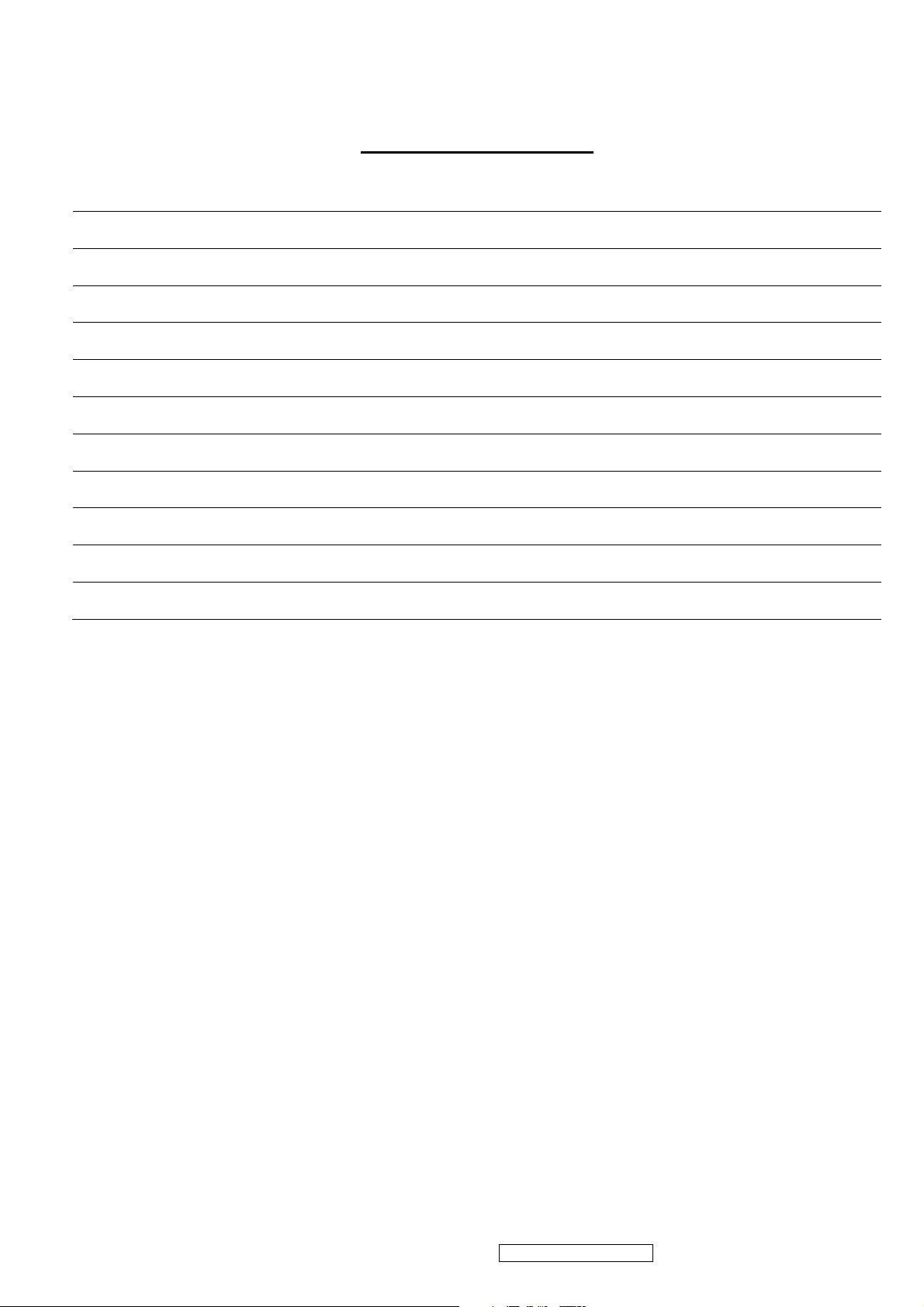
TABLE OF CONTENTS
1. Precautions and Safety Notices 1
2. Specification 4
3. Front Panel Function Control Description 13
4. Circuit Description 17
5. Adjustment Procedure 27
6. Troubleshooting Flow Chart 33
7. Recommended Spare Parts List 40
8. Exploded Diagram and Exploded Parts List 46
9. Block Diagram 50
10. Schematic Diagrams 51
11. PCB Layout Diagrams 59
ViewSonic Corporation Confidential - Do Not Copy VA702-2_VA721-3_VA721b-3
ii

1. Precautions and Safety Notices
SAFETY PRECAUTIONS
This monitor is manufactured and tested on a ground principle that a user’s safety comes first.
However, improper used or installation may cause damage to the monitor as well as to the user.
WARNINGS:
l This monitor should be operated only at the correct power sources indicated on the label on the
rear of the monitor. If you’re unsure of the power supply in you residence, consult your local
dealer or Power Company.
l Use only the special power adapter that comes with this monitor for power input.
l Do not try to repair the monitor by yourself, as it contains no user-serviceable parts. Only the
qualified technician can repair it.
l Do not remove the monitor cabinet. There are high-voltage parts inside that may cause electric
shock to human bodies.
l Stop using the monitor if the cabinet is damaged. Have it checked by a service technician.
l Put your monitor only in a lean, cool, dry environment. If it gets wet, unplug the power cable
immediately and consult your closed dealer.
l Always unplug the monitor before cleaning it. Clean the cabinet with a clean, dry cloth. Apply
non-ammonia based cleaner onto the cloth, not directly onto the glass screen.
l Do not place heavy objects on the monitor or power cord.
PRODUCT SAFETY NOTICE
Many electrical and mechanical parts in this chassis have special safety visual inspections and the
protection afforded by them cannot necessarily be obtained by using replacement components
rated for higher voltage, wattage, etc. Before replacing any of these components read the parts list
in this manual carefully. The use of substitute replacement parts, which do not have the same
safety characteristics as specified in the parts list, may create shock, fire, or other hazards.
SERVICE NOTES
l When replacing parts or circuit boards, clamp the lead wires around terminals before soldering.
l Keep wires away from high voltage, high temperature components and sharp edges.
l Keep wires in their original position so as to reduce interference.
l Adjustment of this product please refers to the user’ manual.
ViewSonic Corporation Confidential - Do Not Copy
1
VA702-2_VA721-3_VA721b-3
Handling and Placing Methods
Correct Methods: Incorrect Methods:
Only touch the metal of the LCD panel or the front
cover of he monitor. Do not touch the surface of the
polarizer.
Surface of the LCD panel is pressed by fingers and
that may cause "Mura".
Take out the monitor with cushions.
Taking out the monitor by grasping the LCD panel.
That may cause "Mura".
ViewSonic Corporation Confidential - Do Not Copy
2
VA702-2_VA721-3_VA721b-3
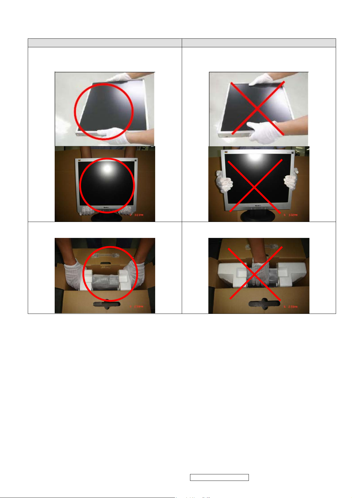
Correct Methods: Incorrect Methods:
Place the monitor on a clean and soft foam pad.
Placing the monitor on foreign objects, That could
scratch the surface of the panel or cause "Mura".
The panel is placed facedown on the lap. That may
cause "Mura".
ViewSonic Corporation Confidential - Do Not Copy
3
VA702-2_VA721-3_VA721b-3
2. Specification
1. INTPRODUCTION
FEATURES VA702/b-2 / VA702/b-2U
Size
Luminance (Typ)
1st panel source
TFTLCD PANEL
Contrast Ratio (Typ) 500:1
Colors (6 bits + 2 bits FRC) 16.2 M
Response Time (Typ) 8 ms
Viewing Angle (H/V) 140 ° / 130 °
Recommend resolution 1280x1024@60Hz
Size
Luminance (Typ)
2nd panel source
TFTLCD PANEL
Contrast Ratio (Typ) 500:1
Colors (6 bits + 2 bits FRC) 16.2 M
Response Time (Typ) 8 ms
Viewing Angle (H/V) 150 ° / 135 °
Recommend resolution 1280x1024@60Hz
Size
Luminance (Typ)
3rd panel source
TFTLCD PANEL
Contrast Ratio (Typ) 600:1
Colors (6 bits + 2 bits FRC) 16.2 M
Response Time (Typ) 8 ms
Viewing Angle (H/V) 150 ° / 135°
Recommend resolution 1280x1024@60Hz
Input Signal
Analog (75ohms, 0.7/1.0 Vp-p) Yes
Digital No
Separate Sync Yes
Sync Compatibility
Composite Sync No
Sync on Green No
PC Yes
Compatibility
Power Mac Yes
TV Box (NextVision 6) Yes
Power Voltage AC 100-240V, 50/60Hz Yes
Power Consumption
On Mode(Max / Typ) 36 W/ 35 W
Off Mode (Max)
Audio No
Tilt ( 20 ° - -5 °)
Ergonomics
Swivel No
Pivot No
Height Adjust No
OSD Control [ 1 ] [▼] [▲] [ 2 ] [ ] Yes
Dimension
Weight
Operating Condition
Storage Condition
Physical (W x H x D) 378 x 374 x 196 mm
Package (W x H x D) 440 x 511 x 132 mm
Physical (Net Weight) 4.5 kg
Package (Gross Weight) 6.2 kg
Temperature ( / )℉℃ 32℉-104℉ / 0℃-40℃
Humidity (%) 10 % - 90 %
Temperature ( / )℉℃ -4℉-140℉ / -20℃-60℃
Humidity (%) 5 % - 90 %
UL, cUL, FCC-B, CB, CE, ENERGY, NOM, TUV/GS, TUV ERGO
Regulation
(covers ISO13406-2 & MPRII), TCO’03, GOST-R+20 ORIGINAL
COPIES HYGIENIC, SASO, PCBC, VCCI, BSMI, CCC, (PSB), (CTICK), TUV-S, Green Mark, Energy Star, WEEE, RoHS
17 “
300 cd/㎡
17 “
300 cd/㎡
17 “
280 cd/㎡
≦1 W
Yes
ViewSonic Corporation Confidential - Do Not Copy
4
VA702-2_VA721-3_VA721b-3
FEATURES VA721/b-3
Size
Luminance (Typ)
1st panel source
TFTLCD PANEL
2nd panel source
TFTLCD PANEL
Input Signal
Sync Compatibility
Compatibility
Power Voltage AC 100-240V, 50/60Hz Yes
Power Consumption
Audio No
Ergonomics
OSD Control [ 1 ] [▼] [▲] [ 2 ] [ ] Yes
Dimension
Weight
Operating Condition
Storage Condition
Regulation
Contrast Ratio (Typ) 500:1
Colors (6 bits + 2 bits FRC) 16.2 M
Response Time (Typ) 8 ms
Viewing Angle (H/V) 150 ° / 135 °
Recommend resolution 1280x1024@60Hz
Size
Luminance (Typ)
Contrast Ratio (Typ) 600:1
Colors (6 bits + 2 bits FRC) 16.2 M
Response Time (Typ) 8 ms
Viewing Angle (H/V) 150 ° / 135°
Recommend resolution 1280x1024@60Hz
Analog (75ohms, 0.7/1.0 Vp-p) Yes
Digital No
Separate Sync Yes
Composite Sync No
Sync on Green No
PC Yes
Power Mac Yes
TV Box (NextVision 6) Yes
On Mode(Max / Typ) 36 W/ 35 W
Off Mode (Max)
Tilt ( 20 ° - -5 °)
Swivel No
Pivot No
Height Adjust No
Physical (W x H x D) 378 x 374 x 196 mm
Package (W x H x D) 440 x 511 x 132 mm
Physical (Net Weight) 4.5 kg
Package (Gross Weight) 6.2 kg
Temperature ( / )℉℃ 32℉-104℉ / 0℃-40℃
Humidity (%) 10 % - 90 %
Temperature ( / )℉℃ -4℉-140℉ / -20℃-60℃
Humidity (%) 5 % - 90 %
UL, cUL, FCC-B, CB, CE, ENERGY, NOM, TUV/GS, TUV ERGO (covers
ISO13406-2 & MPRII), TCO’03, GOST-R+20 ORIGINAL COPIES HYGIENIC,
SASO, PCBC, VCCI, BSMI, CCC, (PSB), (C-TICK), TUV-S, Green Mark,
Energy Star, WEEE, RoHS
17 “
300 cd/㎡
17 “
280 cd/㎡
≦1 W
Yes
2 GENERAL specification
Test Resolution & Frequency 1280x1024 @ 60Hz
Test Image Size Full Size
Factory Default:
Contrast and Brightness Controls
Contrast = 70%, Brightness = 100%
ViewSonic Corporation Confidential - Do Not Copy
5
VA702-2_VA721-3_VA721b-3
3 VIDEO INTERFACE
Analog Input Connector DB-15 (Analog), refer the appendix A
Video Cable Strain Relief
Video Cable Connector DB-15 Pin out Compliant DDC 1/2B
Video Signals Video RGB (Analog) - Separate
Video Impedance 75 Ohms (Analog)
Maximum PC Video Signal 950 mV with no damage to monitor
Maximum Mac Video Signal 1250 mV with no damage to monitor
Sync Signals LVDS
DDC 1/2B Compliant with Revision 1.3
Sync Compatibility Separate Sync
Video Compatibility
Resolution Compatibility
Exclusions Not compatible with interlaced video
Equal to twice the weight of the monitor for five
minutes
Shall be compatible with all PC type computers,
Macintosh computers, and after market video cards
640 x 350, 640 x 480, 720 x 400 (640 x 400*), 800 x
600, 832 x 624, 1024 x 768, 1152 x 870, 1280 x 720,
1280 x 1024
4 POWER SUPPLY
Internal Power Supply Part Number: ILIPI-004
Input Voltage Range 90 TO 264 VAC
Input Frequency Range 47.5 TO 63 HERTZ
Short Circuit Protection Output can be shorted without damage
Over Current Protection 2.4 A typical at 14.2 VDC
Leakage Current 3.5mA (Max) at 254VAC / 60Hz
Efficiency 80% typical at 115VAC Full Load
Fuse Internal and not user replaceable
Power Dissipation 36w (max) / 35 Watts (typ)
Max Input AC Current 0.8 Arms @ 90VAC, 0.4 Arms @265VAC
INRUSH CURRENT (COLD START) 30 A @ 120VAC, 50 A (max) @ 220VAC
Shall start and function properly when
Power Supply Cold Start
under full load, with all combinations of
input voltage, input frequency, and
operating temperature
Shall be able to withstand an ANSI/IEEE
Power Supply Transient Immunity
C62.41-1980 2000V 200 ampere ring wave
transient test with no damage
Shall be able to withstand 1.5 times
Power Supply Line Surge Immunity
nominal line voltage for one cycle with no
damage
Shall be able to function properly, without
Power Supply Missing Cycle Immunity
reset or visible screen artifacts, when ½
cycle of AC power is randomly missing at
nominal input
The power supply shall not produce audible
noise that would be detectable by the user.
Power Supply Acoustics
Audible shall be defined to be in compliance
with ISO 7779 (DIN EN27779:1991) Noise
measurements of machines acoustics.
Power Switch noise shall not be considered
ViewSonic Corporation Confidential - Do Not Copy
6
VA702-2_VA721-3_VA721b-3
US Type Power Cable
European Type Power Cable
Separate 3-prong NEMA 5-15P type plug.
Length = 1.8m. Connects to display.
Color = Black
Schuko CEE7-7 type plug.
Length = 1.8m, Connects to display.
Color = Black
CCC Type Power Cable
Separate 3-prong type plug.
Length = 1.8m. Connects to display.
Color = Black
Separate 2-prong NEMA 1-15P type plug.
PSE Type Power Cable
Length = 1.8m. Connects to display.
Color = Black
Power Saving Operation(Method) VESA DPMS Signaling
On Mode < 36 W (max)
Power Consumption
Off Mode< 1W
Recovery Time On Mode = N/A, Active Off < 3 sec
5 ELECTRICAL REQUIREMENT
Horizontal / Vertical Frequency
Horizontal Frequency 30 – 82 kHz
Vertical Refresh Rate 50 – 85* Hz.
* When the resolution is set to 1280 x 1024, the vertical refresh
rate may be up to 75 Hz; for all other resolutions, the vertical
refresh rate may be up to 85Hz.
Maximum Pixel Clock 140 MHz
Sync Polarity Independent of sync polarity.
Timing Table
Item Timing Analog
1 640 x 350 @ 70Hz, 31.5kHz Yes
2 640 x 400 @ 60Hz, 31.5kHz Yes
3 640 x 400 @ 70Hz, 31.5kHz Yes
4 640 x 480 @ 50Hz, 24.7kHz Yes
5 640 x 480 @ 60Hz, 31.5kHz Yes
6 640 x 480 @ 67Hz, 35.0kHz Yes
7 640 x 480 @ 72Hz, 37.9kHz Yes
8 640 x 480 @ 75Hz, 37.5kHz Yes
9 640 x 480 @ 85Hz, 43.27kHz Yes
10 720 x 400 @ 70Hz, 31.5kHz Yes
11 800 x 600 @ 56Hz, 35.1kHz Yes
12 800 x 600 @ 60Hz, 37.9kHz Yes
13 800 x 600 @ 75Hz, 46.9kHz Yes
14 800 x 600 @ 72Hz, 48.1kHz Yes
15 800 x 600 @ 85Hz, 53.7kHz Yes
16 832 x 624 @ 75Hz, 49.7kHz Yes
17 1024 x 768 @ 60Hz, 48.4kHz Yes
18 1024 x 768 @ 70Hz, 56.5kHz Yes
19 1024 x 768 @ 72Hz, 58.1kHz Yes
ViewSonic Corporation Confidential - Do Not Copy
7
VA702-2_VA721-3_VA721b-3
20 1024 x 768 @ 75Hz, 60.0kHz Yes
21 1024 x 768 @ 85Hz, 68.67kHz Yes
22 1152 x 870 @ 75Hz, 68.7kHz Yes
23 1280 x 1024 @ 60Hz, 63.4kHz Yes
24 1280 x 1024 @ 75Hz, 79.97kHz Yes
25 1280x 720 @ 60Hz, 45kHz (HDTV) Yes
Primary Presets
1280x1024 @ 60Hz
User Presets
Number of User Presets (recognized timings) Available: 10 presets total in FIFO configuration
Changing Modes
● Maximum Mode Change Blank Time for image stability: 3 seconds (Max), excluding “Auto
Image Adjust” time.
● Under DOS mode (640 x 350, 720 x 400 & 640 x 400), it should recall factory setting when
execute “Auto Image Adjust”.
The monitor needs to do “Auto Image Adjust” the first time when a new mode is detected. (See
section “0-Touch™ Function Actions”)
TFT LCD PANEL (for VA702-2)
Panel Characteristics:
st
1
Source Panel
Model number Innolux MT170EN01 V2
Type TN type with LVDS interface
Active Size 337.9 (H) x 270.3 (V)
Pixel Arrangement RGB Vertical Stripe
Pixel Pitch 0.264 mm
GLASS TREATMENT Anti Glare (Hard coating 3H)
# OF BACKLIGHTS 4 CCFL edge-light (2 top / 2 bottom)
BACKLIGHT LIFE 40,000 Hours (Min) / 50,000 (Typ)
Luminance (Center) –
Condition:
CT = 6500K, Contrast = Max,
300 cd/m2 (Typ after 30 minute warm up)
250 cd/m2 (Min after 30 minute warm up)
Brightness = Max
Brightness Uniformity (13 points)
0.8 (Typ), 0.75(Min)
δ = Min Luminance of 13 points/Max
Luminance of 13 points
Contrast Ratio 500:1 (Typ), 400:1 (min)
Color Depth 16.2 million colors (6 bits + 2 bits FRC)
Viewing Angle (Horizontal) @ CR>=10
Typical: 140º
Minimum: 130º
VIEWING ANGLE (VERTICAL)
@ CR>=10
Typical: 130º
Minimum: 110º
Response Time
10%-90% @ Ta=25°C
8 ms (Tr= 2 ms, Tf = 6 ms) (typ)
18 ms (Tr= 7 ms, Tf = 11 ms)(max)
@ CR>= 5
Typical: 160º
Minimum: 140º
@ CR>= 5
Typical: 160º
Minimum: 140º
Panel Defects Please see Panel Quality Specifications.
ViewSonic Corporation Confidential - Do Not Copy
8
VA702-2_VA721-3_VA721b-3
2nd Source Panel
Model number Innolux MT170EN01 V4
Type TN type with LVDS interface
Active Size 337.9 (H) x 270.3 (V)
Pixel Arrangement RGB Vertical Stripe
Pixel Pitch 0.264 mm
GLASS TREATMENT Anti Glare (Hard coating 3H)
# OF BACKLIGHTS 4 CCFL edge-light (2 top / 2 bottom)
BACKLIGHT LIFE 40,000 Hours (Min) / 50,000 (Typ)
Luminance (Center) –
Condition:
CT = 6500K, Contrast = Max,
300 cd/m2 (Typ after 30 minute warm up)
250 cd/m2 (Min after 30 minute warm up)
Brightness = Max
Brightness Uniformity (13 points) 0.8 (Typ), 0.75(Min)
δ = Min Luminance of 13 points/Max
Luminance of 13 points
Contrast Ratio 500:1 (Typ), 400:1 (min)
Color Depth 16.2 million colors (6 bits + 2 bits FRC)
Viewing Angle (Horizontal) @ CR>=10
Typical: 150º
Minimum: 130º
VIEWING ANGLE (VERTICAL)
@ CR>=10
Typical: 135º
Minimum: 115º
Response Time
10%-90% @ Ta=25°C
8 ms (Tr= 2 ms, Tf = 6 ms) (typ)
18 ms (Tr= 7 ms, Tf = 11 ms)(max)
@ CR>= 5
Typical: 170º
Minimum: 150º
@ CR>= 5
Typical: 155º
Minimum: 135º
Panel Defects Please see Panel Quality Specifications.
rd
3
Source Panel
Model number Innolux MT170EN01 V7
Type TN type with LVDS interface
Active Size 337.9 (H) x 270.3 (V)
Pixel Arrangement RGB Vertical Stripe
Pixel Pitch 0.264 mm
GLASS TREATMENT Anti Glare (Hard coating 3H)
# OF BACKLIGHTS 4 CCFL edge-light (2 top / 2 bottom)
BACKLIGHT LIFE 40,000 Hours (Min) / 50,000 (Typ)
Luminance (Center) –
Condition:
CT = 6500K, Contrast = Max,
280 cd/m2 (Typ after 30 minute warm up)
250 cd/m2 (Min after 30 minute warm up)
Brightness = Max
Brightness Uniformity (13 points) 0.8 (Typ), 0.75(Min)
δ = Min Luminance of 13 points/Max
Luminance of 13 points
Contrast Ratio 600:1 (Typ), 500:1 (min)
Color Depth 16.2 million colors (6 bits + 2 bits FRC)
Viewing Angle (Horizontal) @ CR>=10
Typical: 150º
Minimum: 130º
VIEWING ANGLE (VERTICAL)
@ CR>=10
Typical: 135º
Minimum: 115º
Response Time
10%-90% @ Ta=25°C
8 ms (typ)
16 ms (max)
@ CR>= 5
Typical: 170º
Minimum: 150º
@ CR>= 5
Typical: 155º
Minimum: 135º
Panel Defects Please see Panel Quality Specifications.
ViewSonic Corporation Confidential - Do Not Copy
9
VA702-2_VA721-3_VA721b-3
TFT LCD PANEL (for VA721/b-3)
Panel Characteristics:
st
1
Source Panel
Model number Innolux MT170EN01 V4
Type TN type with LVDS interface
Active Size 337.9 (H) x 270.3 (V)
Pixel Arrangement RGB Vertical Stripe
Pixel Pitch 0.264 mm
GLASS TREATMENT Anti Glare (Hard coating 3H)
# OF BACKLIGHTS 4 CCFL edge-light (2 top / 2 bottom)
BACKLIGHT LIFE 40,000 Hours (Min) / 50,000 (Typ)
Luminance (Center) –
Condition:
CT = 6500K, Contrast = Max,
300 cd/m2 (Typ after 30 minute warm up)
250 cd/m2 (Min after 30 minute warm up)
Brightness = Max
Brightness Uniformity (13 points) 0.8 (Typ), 0.75(Min)
δ = Min Luminance of 13 points/Max
Luminance of 13 points
Contrast Ratio 500:1 (Typ), 400:1 (min)
Color Depth 16.2 million colors (6 bits + 2 bits FRC)
Viewing Angle (Horizontal) @ CR>=10
Typical: 150º
Minimum: 130º
VIEWING ANGLE (VERTICAL)
@ CR>=10
Typical: 135º
Minimum: 115º
Response Time
10%-90% @ Ta=25°C
8 ms (Tr= 2 ms, Tf = 6 ms) (typ)
18 ms (Tr= 7 ms, Tf = 11 ms)(max)
@ CR>= 5
Typical: 170º
Minimum: 150º
@ CR>= 5
Typical: 155º
Minimum: 135º
Panel Defects Please see Panel Quality Specifications.
ViewSonic Corporation Confidential - Do Not Copy
10
VA702-2_VA721-3_VA721b-3
2nd Source Panel
Model number Innolux MT170EN01 V7
Type TN type with LVDS interface
Active Size 337.9 (H) x 270.3 (V)
Pixel Arrangement RGB Vertical Stripe
Pixel Pitch 0.264 mm
GLASS TREATMENT Anti Glare (Hard coating 3H)
# OF BACKLIGHTS 4 CCFL edge-light (2 top / 2 bottom)
BACKLIGHT LIFE 40,000 Hours (Min) / 50,000 (Typ)
Luminance (Center) –
Condition:
CT = 6500K, Contrast = Max,
280 cd/m2 (Typ after 30 minute warm up)
250 cd/m2 (Min after 30 minute warm up)
Brightness = Max
Brightness Uniformity (13 points) 0.8 (Typ), 0.75(Min)
δ = Min Luminance of 13 points/Max
Luminance of 13 points
Contrast Ratio 600:1 (Typ), 500:1 (min)
Color Depth 16.2 million colors (6 bits + 2 bits FRC)
Viewing Angle (Horizontal) @ CR>=10
Typical: 150º
Minimum: 130º
VIEWING ANGLE (VERTICAL)
@ CR>=10
Typical: 135º
Minimum: 115º
Response Time
10%-90% @ Ta=25°C
8 ms (typ)
16 ms (max)
@ CR>= 5
Typical: 170º
Minimum: 150º
@ CR>= 5
Typical: 155º
Minimum: 135º
Panel Defects Please see Panel Quality Specifications.
ViewSonic Corporation Confidential - Do Not Copy
11
VA702-2_VA721-3_VA721b-3

Dimension (Desktop)
Width 378mm (14.9 inch)
Height 374 mm (14.7 inch)
Depth 196 mm ( 7.7 inch)
Monitor Weight 4.5 Kg (9.9 lbs)
*Refer to Figure 1
Dimension (Head Only / Wall Mount) – Unfolding the Monitor Stand
Width 378 mm (14.9 inch)
Height 424 mm (16.7 inch)
Depth 61 mm (2.38 inch)
Monitor Weight 4.5 Kg (9.9 lbs)
*Refer to Figure 1
Ergonomics
Tilt Up
Tilt Down
Cabinet Material
Display Head Plastic Material ABS UL94-HB
Neck/Base Plastic Material ABS UL94-HB
Internal Plastic Cabinet Components
Front Bezel Color
Neck, Base, and Rear Cover Color
Rear logo color
Cabinet Color Drift Due To UV-Light
Cabinet Texture
Samples
From 0º up to ≧20º
From 0º down to -3º ~ -5 º
All internal plastic cabinet components shall be in
compliance with the requirements of TCO’03
The reference for the bezel is the silver color
(VA702) and the midnight gray color (VA702b) chip
provided by ViewSonic
The reference for the bezel is the black color
(VA702) and the midnight gray color (VA702b) chip
provided by ViewSonic.
The color difference between any two cabinet
components shall be less than 0.80 “Delta E”, in the
1976 CIE L*a*b Color space.
The rear logo is silver color with the black color
background (VA702) and midnight gray color and
background (VA702b) chip provided by ViewSonic
The color drift due to UV-Light shall be less than 3.0
“Delta E” in the 1976 CIE L*a*b color space. Testing
shall be performed according to the requirements of
ASTM Test Method D4459-93.
Mold-Tech # 11010 used on all external textured
surfaces.
The supplier shall submit textured color chips, plastic
material specifications, and Material Safety Data
Sheets for approval.
ViewSonic Corporation Confidential - Do Not Copy
12
VA702-2_VA721-3_VA721b-3
3. Front Panel Function Control Description
1. Key Function Description
CONTROL KEY KEYS FUNCTION
[AUTO] [2] By pressing [AUTO] key, “Auto Image Adjust” is performed
[MENU] [1] By pressing [MENU] key, Main menu display
A. When “MENU OSD” display, press these keys to change the contents of
[▼] [▲]
an adjustment item, or change an adjustment value
B. When “MENU OSD” is un-display, press these keys to change brightness
and contrast
[POWER] Power on or power off the monitor
2. Hot Key Operation
CONTROL KEY KEYS FUNCTION
Recall Contrast or Brightness while in the Contrast or Brightness adjustment,
[▼] + [▲]
or recall both of Contrast and Brightness when the OSD is not open.
[1] + [2] Toggle 720x400 and 640x400 mode when input 720x400 or 640x400 mode.
[1] + [▼] + [▲]
[1] + [▼]
[1] + [▲]
White Balance (Not shown on user’s guide)
Power Lock
OSD Lock
Remark : All the short cuts function are only available while OSD off
3. OSD Control
3.1 OSD table
Layer 1 Layer 2 Layer 3
Auto Image Adjust
Contrast (+ / -)
Contrast/Brightness
Brightness (+ / -)
Srgb
9300K
6500K
Color Adjust
5400K
User Color
Information
Red (+ / -)
Green (+ / -)
Blue (+ / -)
H/V Position
H Position (+ / -) Manual Image Adjust
V Position (+ / -)
ViewSonic Corporation Confidential - Do Not Copy
13
VA702-2_VA721-3_VA721b-3
H Size + / Fine Tune + / Sharpness + / -
English
French
German
Italian
Language Select
Setup Menu
Resolution Notice On/Off
OSD Position
OSD Time Out
OSD Background On/Off
Memory Recall
3.2 OSD lock Menu function
OSD Lock Menu Function Check
Item Method Phenomenon
Spanish
Finnish
Japanese
Simplified Chinese
Traditional Chinese
H Position (+ / -)
V Position (+ / -)
Press any of buttons"1", "▼",
Activate OSD lock
[1] + [▲] 10S
"▲", "2" will appear "OSD
Locked" 3s
Deactivate OSD lock:
[1] + [▲] 10S(again)
NOTICE:
When the OSD is locked will lock all functions.
Status bar indicating OSD Lock or Unlock is in progress and when complete it will indicate
“OSD Locked”
OSD Lock should not lock Power Button and Power Lock function
ViewSonic Corporation Confidential - Do Not Copy
14
VA702-2_VA721-3_VA721b-3
3.3 Power lock Menu function
Item Method Phenomenon
Power Lock Menu Function Check
Activate Power Lock
Deactivate Power
Lock
NOTICE:
Status bar indicating Power Button lock or unlock is in progress and when complete it will
indicate “Power Button Locked”
Power should only be lockable in the “On State”
3.4 Resolution notice function
[1] + [▼] 10S
[1] + [▼] 10S(again)
Resolution Notice Menu
Can not turn off the LCD;
Press the power button will
appear "Power Button Locked"
OSD 3s;
LCD would automatically turn
back "On" when power is
restored after a power failure
Item Method Phenomenon
Resolution Notice OSD should
show on screen after changing
Activate Resolution
to non-native mode for 30 sec,
------
Notice Menu
And it should disappear after 10s
or by pushing button [1] or [2]
Deactivate
Push button [2] under Resolution
Resolution Notice
-------
Notice OSD, select Disable
Menu
3.5 Factory Mode Introduction
When input the signal, press “power key” to turn off the monitor. Press” [▼] +[▲] +[ ] “at the same time
so as to enter factory mode. After power on, press ‘’Menu[1]’’ key, you can see the Factory menu.
INL : Currently using panel model name
V2 050526 : Currently using firmware version information.
Auto Color : Automatically calibrate chip ADC parameter by using chip internal DAC
Color Temperature : The R, G, B of 9300K and 6500K and 5400K and User Mode
Colors are all generated from scaling back end.
ViewSonic Corporation Confidential - Do Not Copy
15
VA702-2_VA721-3_VA721b-3

4. Circuit Description
4.1 Switching Mode Power Supply
4.1.1 AC Current Input Circuit
P801 is a connector for connecting AC Power. F801 is a fuse to protect all the circuit. AC input
voltage is from 90V to 264V. R820 and R821 joined between two inputting main circuit to prevent
man from shock. L801 is used to clear up low frequency wave. C801 and C806 are used to
discharge the waves that L801 produced. High frequency waves are damped by C801 and C806.
D801 is a rectifier which composed of 4 build-in diodes, it inverts AC to DC.
4.1.2High Voltage to Low Voltage Control Circuit
C805 is used to smooth the wave from rectifier. IC802 is a highly integrated PWM controller, which
build-in a power MOSFET. When rectified DC high voltage is applied to the DRAIN pin during
start-up, the MOSFET is off initially, and the CONTROL pin capacitor is charged through a
switched high voltage current source connected internally between the DRAIN and CONTROL
pins. When the CONTROL pin voltage Vc reaches approximately 5.8V, the control circuitry is
activated and the soft-start begins. The soft-start circuit gradually increases the duty cycle of the
MOSFET from zero to the maximum value over approximately 10ms. If no external
feedback/supply current is fed into the CONTROL pin by the end of the soft-start, the high voltage
current source is turned off and the CONTROL pin will start discharging in response to the supply
current drawn by the control circuitry.
Resistor R803, R807, R824 and R825 are for line over voltage shut-down (OVP) and line
under-voltage detection (UVP).Resistors R801, R805, R822, and R823 are for external current
limit adjustment, and used to reduce the current limit externally to a value close to the operating
peak current of primary about 1.35A. The mean is power will protected when the primary current
over about 1.35A.
When PWM is turned off, the main current flow will be consumed through D804 and ZD802, This
will prevent MOSFET which built-in IC802 from being damaged under large current impulse and
voltage spike.
D806 and C815 provide internal Auxiliary current to CONTROL pin during normal operation. In
addition, error amplifier and feedback current to the CONTROL pin are for duty cycle control.
4.1.3DC_5V and DC_14V Output Circuit
For DC 5V, D805 is used to rectify the inducted current. R806 and C811 are used to store energy
when current is reversed. The parts including C812, C814, C822, C821, B801 and L803 are used
to smooth the current waves.
For DC 14V, D803 is used to rectify the inducted current. R802 and C802 are used to store energy
when current is reversed. The parts including C808, C810 and L802 are used to smooth the
current waves.
4.1.4Feedback and OVP Protect Circuit
Pin R of IC803 is supplied 2.5V stable voltage. It is connected to 5V and 14V output through R811,
R810 and R818. R811, R810 and R818 are output sampling resistor. When the sampling voltage
more than 2.5V or less than 2.5V, feedback current of IC802 will change, this can change the
voltage from transformer T801.
For 5VDC output OVP, ZD803 is a zener diode, when 5V output voltage becomes up to 5.6V, the
ViewSonic Corporation Confidential - Do Not Copy
16
VA702-2_VA721-3_VA721b-3

zener current cause R819 voltage become up to 0.7V, Q801 is triggered and OVP starts. For
12VDC output OVP, ZD804 is a Zener Diode, when 14V output voltage becomes up to 16V, the
zener current cause R819 voltage become up to 0.7V, Q801 is triggered and OVP starts. The
collector current of Q801 is used to make build-in diode light. FB Current of IC802 will be changed;
it can change the voltage from T801.
Q802, R827, R828 and ZD801 make up of dummy loading circuit. For start-up sequence, during
5V output take place high loading first, this dummy loading circuit operated to insure 14V not be
increased.
4. 2 Inverter circuit
4.2.1Low voltage to high voltage circuit
12VDC supplies the power to IC501 through F501; the control signals that BRIGHTNESS and
ON/OFF come from I/F board. ON/OFF signal connect to pin8 of IC501 and makes IC501 enabled.
BRIGHTNESS is connected to pin7 of IC501 to adjust the panel luminance. R524, R529, C505
make up of a delay-time circuit and R528, R523, R524 make up of a voltage divided circuit. C504
is used to filter the high frequency noise. The operation frequency is determined by R522 and
C529. For BURST MODE, its dimming frequency is determined by R527 and C506. C502 is used
for soft start and compensation, C502, C528 are used to filter noise.
The output drives, including NDR4, NDRV2, PDRV3, PDRV1 (pins1, 3, 15, 16 respectively),
generate a square pulses to drive MOSFET U501, U502. And U501, U502 works as full-bridge
topology, it is high efficient, zero voltage switch.
During start up, VSEN (pin9) detects the voltage at the transformer secondary. When VSEN
reaches 3.0V, the output voltage is regulated. If no current is detected for around 1.5 seconds,
IC501 will shut down.
The current flowing through CCFL is detected and regulated through sense resistor R509, R511.
The feedback voltage through R506, R507, and C508 connected to Pin11 (ISEN), and then
compared with a reference voltage (1.5V) via a current amplifier, resulting in PWM drive outputs to
full-bridge switches.
4.2.2Protection circuit
Over Voltage Protection: R501and R502 are connected in high voltage output connector, the
divided AC voltage is inverted DC voltage through D508, R505 and C507are used to rectify wave
& dump noise. Then the voltage signal reaches Pin9 VSEN of IC501, when the voltage changes,
build-in PWM of IC501 will adjust output voltage.
Open Lamp Protection: In normal operation, the resistors R510, R511, R512, R509 are sensed a
high level AC voltage, the AC signal IS1 invert DC voltage through D509, R515, C533, and the
high level DC voltage reaches the gate pin of Q502, similarly, the gate pin of Q503, Q504, Q505
has high level DC voltage. So the gate pin of Q501 has a low level voltage, and the IC501 is
normal operation. Once one of signal IS1, IS2, IS3, and IS4 is low, the voltages of Q501 gate pin
is high level, and make the voltage of ISEN low level, the IC501 will shut down.
4.3I/F Board Circuit
4.3.1Power Input
ViewSonic Corporation Confidential - Do Not Copy
17
VA702-2_VA721-3_VA721b-3
 Loading...