

Page 1

ViewSonic VA503b-1
VA503m-1
Model No. VS11248
15” Color TFT LCD Display
(VA503b-1_ VA503m-1_SM Rev. 1c Nov. 2006)
ViewSonic 381 Brea Canyon Road, Walnut, California 91789 USA – (800) 888-8583
Service Manual
Page 2

ViewSonic Corporation VA503b-1_ VA503m-1
i
Copyright
Copyright © 2006 by ViewSonic Corporation. All rights reserved. No part of this publication
may be reproduced, transmitted, transcribed, stored in a retrieval system, or translated into any
language or computer language, in any form or by any means, electronic, mechanical, magnetic,
optical, chemical, manual or otherwise, without the prior written permission of ViewSonic
Corporation.
Disclaimer
ViewSonic makes no representations or warranties, either expressed or implied, with respect to
the contents hereof and specifically disclaims any warranty of merchantability or fitness for any
particular purpose. Further, ViewSonic reserves the right to revise this publication and to make
changes from time to time in the contents hereof without obligation of ViewSonic to notify any
person of such revision or changes.
Trademarks
Revision History
Revision SM Editing Date ECR Number Description of Changes Editor
1a 05/10/2006 Initial Release Jamie Chang
Confidential - Do Not Copy
1b 08/01/2006 VS-E060194 Add 2nd panel source( HSD A02) Jamie Chang
Optiquest is a registered trademark of ViewSonic Corporation.
ViewSonic is a registered trademark of ViewSonic Corporation.
All other trademarks used within this document are the property of their respective owners.
1c 11/17/2006 VS-E060417 Add SVA NEC XG04 TB panel source Jamie Chang
Page 3
ViewSonic Corporation VA503b-1_ VA503m-1
ii
TABLE OF CONTENTS
1. Precautions and Safety Notices 1
2. Specification 4
3. Front Panel Function Control Description 13
4. Circuit Description 19
5. Adjustment Procedure 26
6. Troubleshooting Flow Chart 50
7. Recommended Spare Parts List 51
8. Exploded Diagram and Exploded Parts List 57
9. Block Diagram 67
10. Schematic Diagrams 68
11. PCB Layout Diagrams 75
Confidential - Do Not Copy
Page 4

ViewSonic Corporation VA503b-1_ VA503m-1
1
1. Precautions and Safety Notices
1.1 SAFETY PRECAUTIONS
This monitor is manufactured and tested on a ground principle that a user’s safety comes
first. However, improper use or installation may cause damage to the monitor as well as
the user. Carefully go over the following WARNINGS before installing and keep this guide
handy.
WARNINGS
.This monitor should be operated only at the correct power sources indicated on the label
on the rear end of the monitor. If you’re unsure of the power supply in your residence,
consult you local dealer or power company.
.Use only the special power adapter that comes with this monitor for power input.
.Do not try to repair the monitor your self as it contains no user-serviceable parts. This
monitor should only be repaired by a qualified technician.
.Do not remove the monitor cabinet. There is high-voltage parts inside that may cause
electric shock to human bodies, even when the power cord is unplugged.
.Stop using the monitor if the cabinet is damaged. Have it checked by a service technician.
.Put your monitor only in a clean, dry environment. If it gets wet, unplug the power cable
immediately and consult your service technician.
.Always unplug the monitor before cleaning it .Clean the cabinet with a clean, dry cloth.
Apply non-ammonia based cleaner onto the cloth, not directly onto the glass screen.
.Keep the monitor away from magnetic objects, motors, TV sets, and transformer.
.Do not place heavy objects on the monitor or power cord.
1.2 PRODUCT SAFETY NOTICE
Many electrical and mechanical parts in this chassis have special safety visual inspections
and the protection afforded by them cannot necessarily be obtained by using replacement
components rated for higher voltages, wattage, etc. Before replacing any of these
components read the parts list in this manual carefully. The use of substitute replacement
parts which do not have the same safety characteristics as specified in the parts list may
create shock, fire ,or other hazards.
1.3 SERVICE NOTES
1. When replacing parts or circuit boards, clamp the lead wires around terminals before
soldering.
2. When replacing a high wattage resistor(more than 1W of metal oxide film resistor) in
circuit board, keep the resistor about 5mm away from circuit board.
3. Keep wires away from high voltage, high temperature components and sharp edges.
4. Keep wires in their original position so as to reduce interference.
5. Usage of this product please refer to also user’s manual.
Confidential - Do Not Copy
Page 5
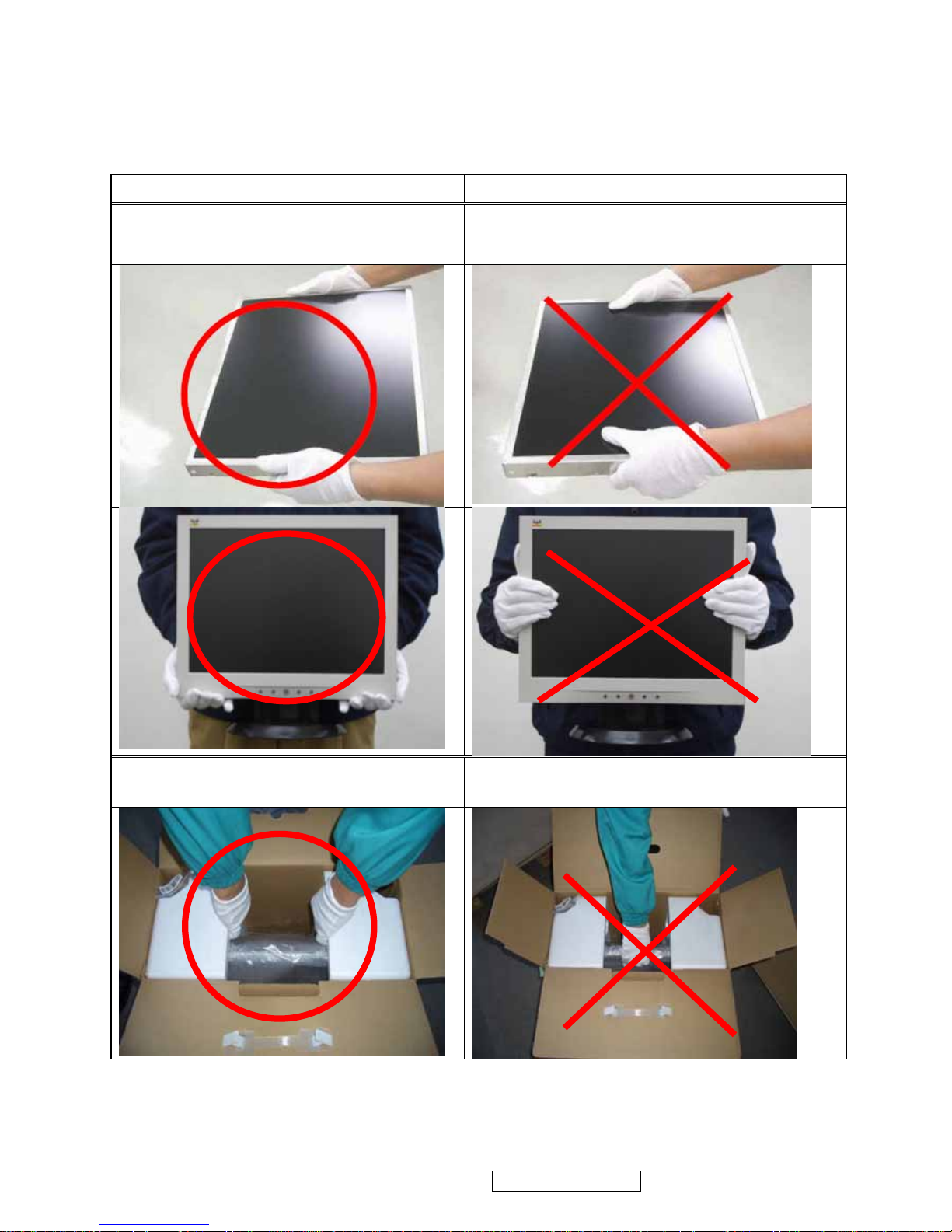
1.4 HANDING AND PLACING METHODS
Correct Methods: Incorrect Methods:
Only touch the metal frame of the LCD
panel or the front cover of the monitor. Do
not touch the surface of the polarizer.
Surface of the LCD panel is pressed by fingers
and that may cause “Mura.”
Take out the monitor with cushions
Taking out the monitor by grasping the LCD
panel. That may cause “Mura.”
ViewSonic Corporation VA503b-1_ VA503m-1
2
Confidential - Do Not Copy
Page 6
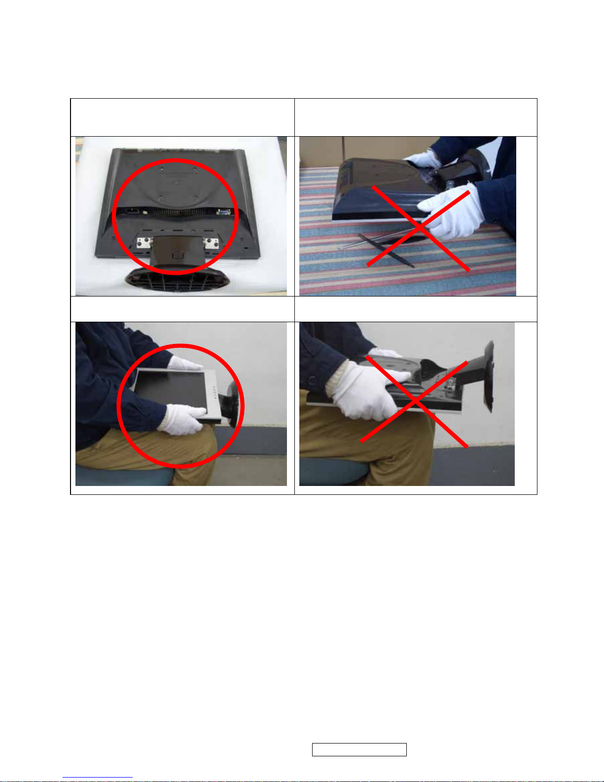
Place the monitor on a clean and soft foam
pad.
Placing the monitor on foreign objects. That
could scratch the surface of the panel or cause
“Mura.”
Place the monitor on the lap, the panel
surface must be upwards.
The panel is placed facedown on the lap. That
may cause “Mura.”
ViewSonic Corporation VA503b-1_ VA503m-1
3
Confidential - Do Not Copy
Page 7
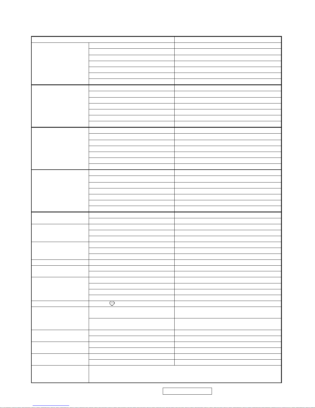
INTRODUCTION
FEATURES VA503b / VA503m
Size 15 “
Luminance (Typ)
250 cd/㎡
Contrast Ratio (Typ) 500:1
Colors 16.2 M colors (6+2bit panel)
Response Time (Typ) 12 ms
Viewing Angle (H/V) 120 ° / 100 °
1st TFT LCD panel
Recommend resolution 1024 x 768 @60Hz
Size 15 “
Luminance (Typ)
200 cd/㎡
Contrast Ratio (Typ) 500 :1
Colors 16.2 M colors (6+2bit panel)
Response Time (Typ) 12 ms
Viewing Angle (H/V) 140 ° / 120 °
2nd TFT LCD panel
Recommend resolution 1024 x 768 @60Hz
Size 15 “
Luminance (Typ)
250 cd/㎡
Contrast Ratio (Typ) 500:1
Colors 16.2 M colors (6+2bit panel)
Response Time (Typ) 12 ms
Viewing Angle (H/V) 120 ° / 100 °
3rd TFT LCD panel
Recommend resolution 1024 x 768 @60Hz
Size 15 “
Luminance (Typ)
250 cd/㎡
Contrast Ratio (Typ) 450:1
Colors 16.2 M colors (6+2bit panel)
Response Time (Typ) 16 ms
Viewing Angle (H/V) 120 ° / 100 °
4th TFT LCD panel
Recommend resolution 1024 x 768 @60Hz
Analog (75ohms, 0.7/1.0 Vp-p) Yes
Input Signal
Digital (DVI-D) No
Separate Sync Yes
Composite Sync No
Sync Compatibility
Sync on Green No
PC Yes
Power Mac Yes
Compatibility
TV Box (NextVision 6) Yes
Power Voltage AC 100-240V, 50/60Hz Yes
On Mode(Max / Typ) Under 23 W in max
Power Consumption
Active Off Mode (Max) Saving mode< 2W / Off mode <1 W
Tilt ( -5 ° - 22.5 °)
Yes
Swivel No
Pivot No
Ergonomics
Height Adjust No
OSD Control [ 1 ] [ 2 ] [ ][▼] [▲] Yes
Physical (W x H x D) 344 x 347.5 x 147 (mm)
13.15 x 13.68 x 5.79 (in)
Dimension
Package (W x H x D) 396 x 400 x 141 (mm)
15.59 x 15.75 x 5.55 (in
Physical (Net Weight) 2.7 kg / 5.95 lbs
Weight
Package (Gross Weight) 3.7 kg / 8.16 lbs
Temperature (℉/℃) 32℉~104℉ / 0℃~40℃
Operating Condition
Humidity (%) 20 % - 90 %
Temperature (℉/℃) -4℉~140℉ / -20℃~60℃
Storage Condition
Humidity (%) 5 % - 90 %
Regulation
CB / TCO99 / UL/cUL / FCC-B / ICES 003 / Argentina-TUV/S / NOM / EPA Energy Star /
TUV/Ergo / ISO134062 / TUV/GS / CE / GOST-R / SASO / BSMI / PSB / C-Tick / CCC / RoHS
/ WEEE
ViewSonic Corporation VA503b-1_ VA503m-1
4
Confidential - Do Not Copy
2. Specification
Page 8
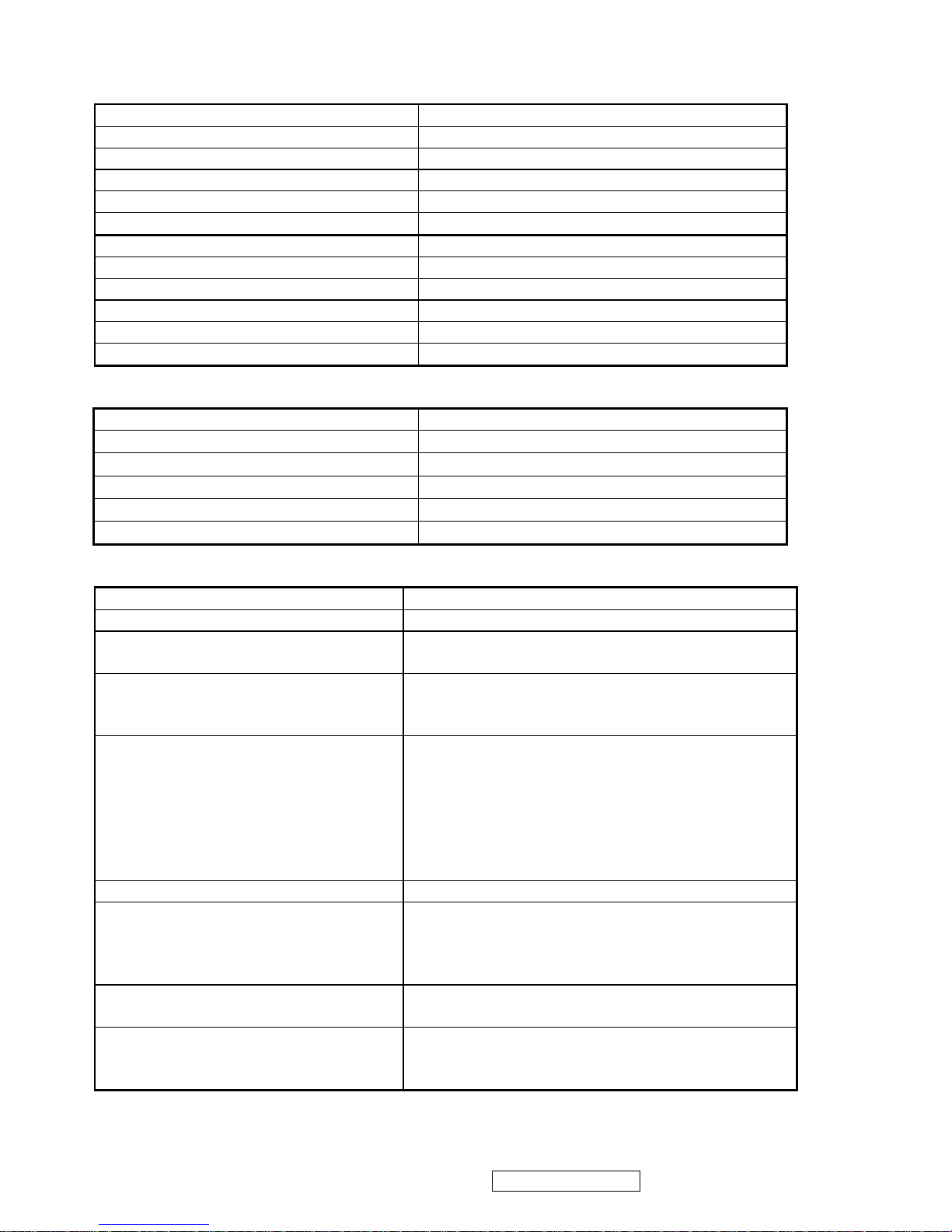
1 GENERAL specification
Test Resolution & Frequency 1024 x 768 @ 60Hz
Test Image Size Full Size
Contrast and Brightness Controls
Factory Default:
Contrast = 70%, Brightness = 100%
2 VIDEO INTERFACE
Analog Input Connector DB-15 (Analog), refer the appendix A
Default Input Connector Defaults to the first detected input
Video Cable Strain Relief
Equal to twice the weight of the monitor for five
minutes
Video Cable Connector DB-15 Pin out Compliant DDC 1/2B
Video Signals 1. Video RGB (Analog), Separate
Video Impedance 75 Ohms (Analog)
Maximum PC Video Signal 950 mV with no damage to monitor
Maximum Mac Video Signal 1250 mV with no damage to monitor
Sync Signals LVDS
DDC 1/2B Compliant with Revision 1.3
Sync Compatibility Separate Sync
Video Compatibility
Shall be compatible with all PC type computers,
Macintosh computers, and after market video
cards
Resolution Compatibility
640 x 350, 640 x 480, 720 x 400 (640 x 400),
800 x 600, 832 x 624, 1024 x 768
Exclusions Not compatible with interlaced video
3 POWER SUPPLY
Internal Power Supply Part Number: 715G1823-I
Input Voltage Range 100 TO 240 VAC
Input Frequency Range 50 TO 60 HERTZ
Short Circuit Protection Output can be shorted without damage
Over Current Protection (1)13V_4.5A@5V_1.5A
(2)5V_6A@13V_2A
Leakage Current 3.5 mA (Max) at 254VAC / 60Hz
Efficiency 80 % typical at 115VAC Full Load
Fuse Internal and not user replaceable
Power Dissipation 4 Watts (typ)
Max Input AC Current 1 Arms @ 90VAC, 0.5 Arms @180VAC
Inrush Current (Cold Start) 60 A @ 240 VAC, 30 A(max) @ 110 VAC
Power Supply Cold Start
Shall start and function properly when under full load, with
all combinations of input voltage, input frequency, and
operating temperature
Power Supply Transient Immunity
Shall be able to withstand an ANSI/IEEE C62.41-1980
6000V 200 ampere ring wave transient test with no damage
Power Supply Line Surge Immunity
Shall be able to withstand 1.5 times nominal line voltage
for one cycle with no damage
Power Supply Missing Cycle Immunity
Shall be able to function properly, without reset or visible
screen artifacts, when ½ cycle of AC power is randomly
missing at nominal input
Power Supply Acoustics
The power supply shall not produce audible noise that
would be detectable by the user. Audible shall define to be
ViewSonic Corporation VA503b-1_ VA503m-1
5
Confidential - Do Not Copy
Page 9
in compliance with ISO 7779 (DIN EN27779:1991) Noise
measurements of machines acoustics. Power Switch noise
shall not be considered
US Type Power Cable Length = 1.8m. Connects to AC/DC Power Color = Black
Power Saving Operation(Method) VESA DPMS Signaling
Power Consumption
ON Mode < 23 W (max)
POWER SAVING < 2W ,OFF < 1W
Recovery Time On Mode = N/A, Active Off < 3 sec
4 ELECTRICAL REQUIREMENT
Horizontal / Vertical Frequency
Horizontal Frequency 30 – 62 KHZ
Vertical Refresh Rate 50 – 85 HZ.
Maximum Pixel Clock 80 MHz
Sync Polarity Independent of sync polarity.
Timing Table
Item Timing Analog
1 640 x 350 @ 70Hz, 31.5kHz
Yes
2 640 x 400 @ 70Hz
Yes
3 640 x 480 @ 50Hz
Yes
4 640 x 480 @ 60Hz, 31.5kHz
Yes
5 640 x 480 @ 67Hz, 35.0kHz
Yes
6 640 x 480 @ 72Hz, 37.9kHz
Yes
7 640 x 480 @ 75Hz, 37.5kHz
Yes
8 640 x 480 @ 85Hz, 43.27kHz
Yes
9 720 x 400 @ 70Hz, 31.5kHz
Yes
10 800 x 600 @ 56Hz, 35.1kHz
Yes
11 800 x 600 @ 60Hz, 37.9kHz
Yes
12 800 x 600 @ 72Hz, 48.1kHz
Yes
13 800 x 600 @ 75Hz, 46.9kHz
Yes
14 800 x 600 @ 85Hz, 53.7kHz
Yes
15 832 x 624 @ 75Hz, 49.7kHz
Yes
16 1024 x 768 @ 60Hz, 48.4kHz
Yes
17 1024 x 768 @ 70Hz, 56.5kHz
Yes
18 1024 x 768 @ 72Hz, 58.1kHz
Yes
19 1024 x 768 @ 75Hz, 60.0kHz
Yes
*1. Tolerance ≧ ± 2kHz.
*2. Any timing not in the list, it should display as normal or show on “OUT OF RANGE” OSD message
without blanking.
*3. The image quality of 85Hz mode might be worse than 75Hz.
AUDIO INTERFACE (SPEAKER SPECIFICATION) (For VA503m only)
Line input connection 3.5 mm stereo jack
Line input signal 1.0Vrms
Line input impedance >10 kOhm
Maximum power output (Electric) 1 W @ < 8% distortion
Signal to Noise Ratio 50 dB
Frequency response 500 Hz – 20 Khz
Distortion < 8 % THD (@1kHz)
ViewSonic Corporation VA503b-1_ VA503m-1
6
Confidential - Do Not Copy
Page 10
Vibration
There should be no audible vibration with volume at
100%. (Input signal within 1.0 Vrms)
Screen image
There should be no affect on the screen image stability
under any conditions
Connector PC99 requirement Audio in Lime Green pantone # 577C
Cable type / length 3.5mm stereo cable / 1.8m length
Audio DPMS
Note: There is no guarantee <1 W power consumption in
Active Off mode, when the Audio Cable is connected
ViewSonic Corporation VA503b-1_ VA503m-1
7
Confidential - Do Not Copy
Page 11

TFT LCD PANEL
1st Panel Source HSD 150MX17 A01
Type TN, LVDS
Active Size 304.1 mm (H) x 228.1mm (V)
Pixel Arrangement RGB Vertical Stripe
Pixel Pitch 0.297 mm
Glass Treatment Anti Glare (Hard coating 3H)
# of Backlights 2 CCFL edge-light
Backlight Life 30,000 Hours (Min)
Luminance –Condition: CT = 6500 K
Contrast = Max, Brightness = Max
250 cd/m2 (Typ after 30 minute warm up)
200 cd/m2 (Min after 30 minute warm up)
Brightness Uniformity 75 % (min)
Contrast Ratio 500 :1 (Typ), 400 :1 (Min)
Color Depth Vertical) 16.2 million colors (6+2 bit panel)
Viewing Angle (Horizontal)
120° (Typ)@ CR>10 / X° (Typ)@ CR>5
Viewing Angle (Vertical)
100° (Typ) @ CR>10 / X° (Typ)@ CR>5
Response Time
10%-90% @ Ta=25°C
12 ms (Tr= 8.5 ms, Tf = 3.5 ms) (Typ)
18 ms (Tr= 5 ms, Tf = 11 ms) (max)
Panel Defects Please see Panel Quality Specifications.
2nd Panel Source AUO, M150XN07 v3
Type TN, LVDS
Active Size 304.128 mm (H) x 228.096mm (V)
Pixel Arrangement RGB Vertical Stripe
Pixel Pitch 0.297 mm
Glass Treatment Anti Glare (Hard coating 3H)
# of Backlights 2 CCFL edge-light
Backlight Life 30,000 Hours (at 8.0mA)
Luminance –Condition: CT = 6500 K
Contrast = Max, Brightness = Max
200 cd/m2 (Typ after 30 minute warm up)
150 cd/m2 (Min after 30 minute warm up)
Brightness Uniformity 80%(typ) / 75 % (min)
Contrast Ratio 500 :1 (Typ), 400 :1 (Min)
Color Depth Vertical) 16.2 million colors (6+2 bit panel)
Viewing Angle (Horizontal) 140° (Typ)@ CR>10 / 140° (Typ)@ CR>5
Viewing Angle (Vertical) 120° (Typ) @ CR>10 / 130° (Typ)@ CR>5
Response Time
10%-90% @ Ta=25°C
12 ms (Tr= 8.5 ms, Tf = 3.5 ms) (Typ)
16 ms (Tr= 11 ms, Tf = 5 ms) (max)
Panel Defects Please see Panel Quality Specifications.
ViewSonic Corporation VA503b-1_ VA503m-1
8
Confidential - Do Not Copy
Page 12
3rd Panel Source HSD 150MX17 A02
Type TN, LVDS
Active Size 304.1 mm (H) x 228.1mm (V)
Pixel Arrangement RGB Vertical Stripe
Pixel Pitch 0.297 mm
Glass Treatment Anti Glare (Hard coating 3H)
# of Backlights 2 CCFL edge-light
Backlight Life 30,000 Hours (Min)
Luminance –Condition: CT = 6500 K
Contrast = Max, Brightness = Max
250 cd/m2 (Typ after 30 minute warm up)
200 cd/m2 (Min after 30 minute warm up)
Brightness Uniformity 75 % (min)
Contrast Ratio 500 :1 (Typ), 400 :1 (Min)
Color Depth Vertical) 16.2 million colors (6+2 bit panel)
Viewing Angle (Horizontal)
120° (Typ)@ CR>10 / X° (Typ)@ CR>5
Viewing Angle (Vertical)
100° (Typ) @ CR>10 / X° (Typ)@ CR>5
Response Time
10%-90% @ Ta=25°C
12 ms (Tr= 8.5 ms, Tf = 3.5 ms) (Typ)
18 ms (Tr= 5 ms, Tf = 11 ms) (max)
Panel Defects Please see Panel Quality Specifications.
4th Panel Source SVA 150XG04TB
Type TN, LVDS
Active Size 304.1 mm (H) x 228.1mm (V)
Pixel Arrangement RGB Vertical Stripe
Pixel Pitch 0.297 mm
Glass Treatment Anti Glare (Hard coating 3H)
# of Backlights 2 CCFL edge-light
Backlight Life 30,000 Hours (Min)
Luminance –Condition: CT = 6500 K
Contrast = Max, Brightness = Max
250 cd/m2 (Typ after 30 minute warm up)
200 cd/m2 (Min after 30 minute warm up)
Brightness Uniformity 75 % (min)
Contrast Ratio 450 :1 (Typ), 350 :1 (Min)
Color Depth Vertical) 16.2 million colors (6+2 bit panel)
Viewing Angle (Horizontal)
120° (Typ)@ CR>10 / X° (Typ)@ CR>5
Viewing Angle (Vertical)
100° (Typ) @ CR>10 / X° (Typ)@ CR>5
Response Time
10%-90% @ Ta=25°C
16 ms (Tr= 4 ms, Tf = 12 ms) (Typ)
25 ms (Tr= 7 ms, Tf = 18 ms) (max)
Panel Defects Please see Panel Quality Specifications.
ViewSonic Corporation VA503b-1_ VA503m-1
9
Confidential - Do Not Copy
Page 13
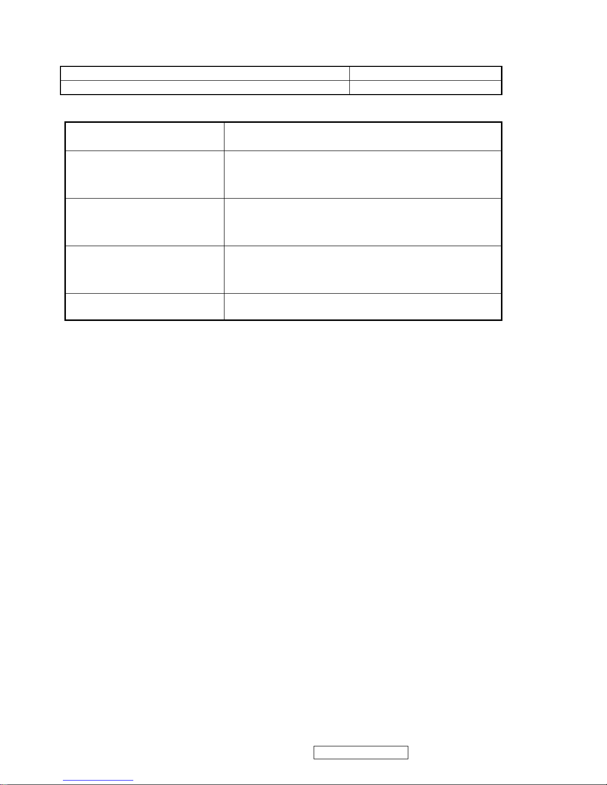
IMAGE PERFORMANCE
Display Size
Horizontal Display Size, Primary Preset Full Screen
Vertical Display Size, Primary Preset Full Screen
Preset Color Temperatures
sRGB
It should meet IEC 61966-2-1 (1999-10) standard.
CCT (typ) = 9300K (u’CCT=0.1888; v’ CCT=0.4457)
CCT (max) = 10250K, CCT (min) = 8500K
Preset 1(9300K)
CCT(Max) = 10250K
CCT(Min) = 8500K
Δu’v’<0.01 (@ Full White pattern)
CCT (typ) = 6500K (u’CCT=0.1978; v’ CCT=0.4684)
CCT (max) = 7595K, CCT (min) = 5930K
Preset 2 (Primary)(6500K)
CCT(Max) = 7595K
CCT(Min) = 5930K
Δu’v’<0.01 (@ Full White pattern)
CCT (typ) = 5400K (u’CCT=0.2044; v’ CCT=0.4808)
CCT (max) = 5830K, CCT (min) = 4860K
Preset 3(5400K)
CCT(Max) = 5830K
CCT(Min) = 4860K
Δu’v’<0.01 (@ Full White pattern)
Preset Color Temperature
Each color preset shall be adjustable. Red, Green, and Blue
shall be individually controlled.
Video Cards Compatibility
Peaking Performance: Peaking is not adjustable
Raster Artifacts
● Video Artifacts : No visible streaking, sag, or smearing artifacts when driven by the specified video
cards in the primary mode and after user adjustment to best condition
● Power Supply, and Grounding Artifacts : No visible artifacts in any specified video mode within the
horizontal or vertical frequency range of the monitor
Temperature Drift : Image shall not drift or lose fine-tune adjustment
ViewSonic Corporation VA503b-1_ VA503m-1
10
Confidential - Do Not Copy
Page 14
MECHANICAL
Dimension
Dimension (Desktop) 344mm(W)*347.5mm(H)*147mm(D)
Width 344mm
Height (Height adjust to the bottom) 347.5mm
Depth 147mm
Monitor Weight 2.7Kg(N/W); 3.7Kg(G/W)
*Refer to Figure 1
Dimension (Head Only / Wall Mount) 344mm (W)*290mm(H)*54mm(D)
Width 344mm
Height 290mm
Depth 54mm
Monitor Weight 2.4Kg
*Refer to Figure 1
Ergonomics
Tilt Up step 1 0° to 20°±2.5°
Tilt Down N/A
Swivel Right N/A
Swivel Left N/A
Height Adjust N/A
Pivot N/A
Cabinet Material
Display Head Plastic Material Samsung starex ABS SD-0150 (94HB)
Neck/Base Plastic Material Samsung starex ABS SD-0150 (94HB)
Internal Plastic Cabinet Components
All internal plastic cabinet components shall be in
compliance with the requirements of TCO99
Front Bezel Color
The reference for the bezel is the silver color
(VA503m) and the midnight gray color (VA503b)
chip provided by ViewSonic
Neck, Base, and Rear Cover Color
The reference for the bezel is the black color
(VA503m) and the midnight gray color
(VA503b) chip provided by ViewSonic.
The color difference between any two cabinet
components shall be less than 0.80 “Delta E”,
in the 1976 CIE L*a*b Colorspace.
Rear logo color Mold type
Cabinet Color Drift Due To UV-Light
The color drift due to UV-Light shall be less than 3.0
“Delta E” in the 1976 CIE L*a*b colorspace.
Testing shall be performed according to the
requirements of ASTM Test Method D4459-93.
Cabinet Texture
Mold-Tech # 11010 used on all external textured
surfaces.
Samples
The supplier shall submit textured color chips, plastic
material specifications, and Material Safety Data
Sheets for approval.
ViewSonic Corporation VA503b-1_ VA503m-1
11
Confidential - Do Not Copy
Page 15
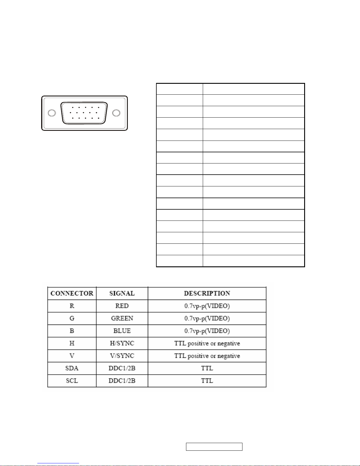
INTERFACE DESCRIPTION
D-SUB 15 PIN CONNECTOR
15
6
10
11 15
SIGNAL LEVEL
Pin Number Pin Function
1 Red video input
2 Green video input
3 Blue video input
4 No Connection
5 Ground
6 Red video ground
7 Green video ground
8 Blue video ground
9 +5V
10 H/V sync ground
11 No connection
12 (SDA)
13 Horizontal sync (Composite sync)
14 Vertical sync
15 (SCL)
ViewSonic Corporation VA503b-1_ VA503m-1
12
Confidential - Do Not Copy
Page 16
ViewSonic Corporation VA503b-1_ VA503m-1
13
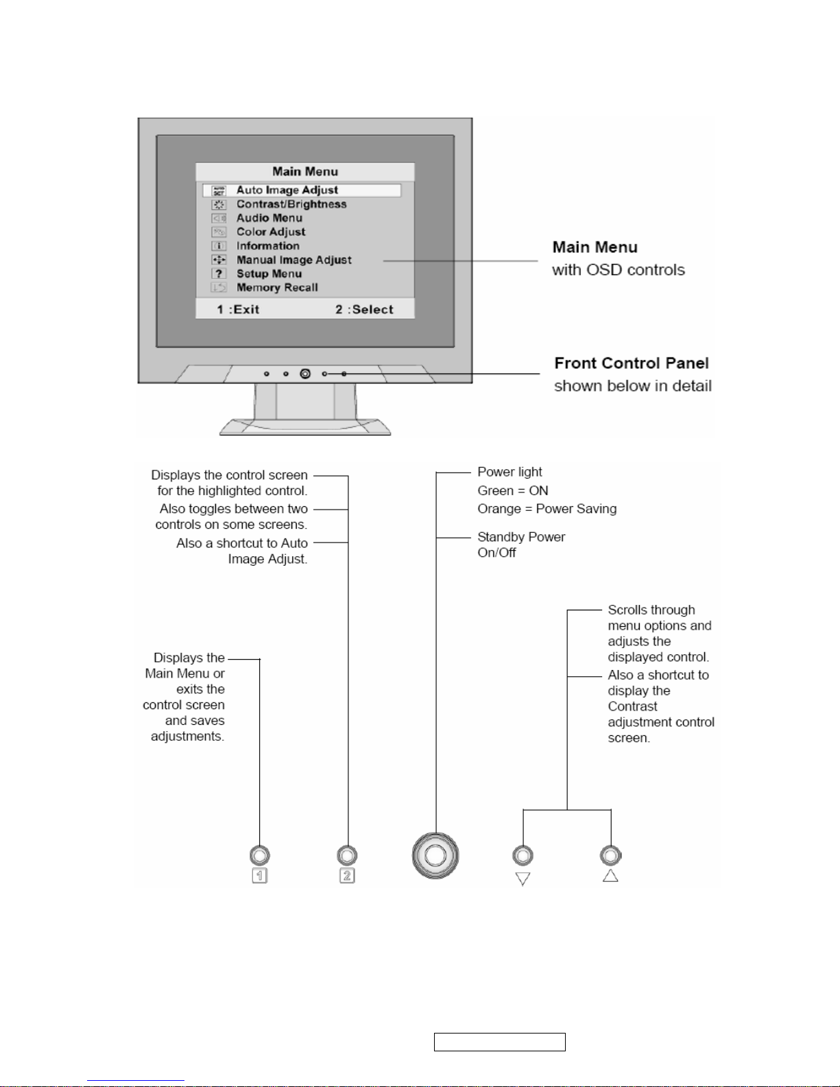
3. Front Panel Function Control Description
Confidential - Do Not Copy
Page 17
Do the following to adjust the display setting:
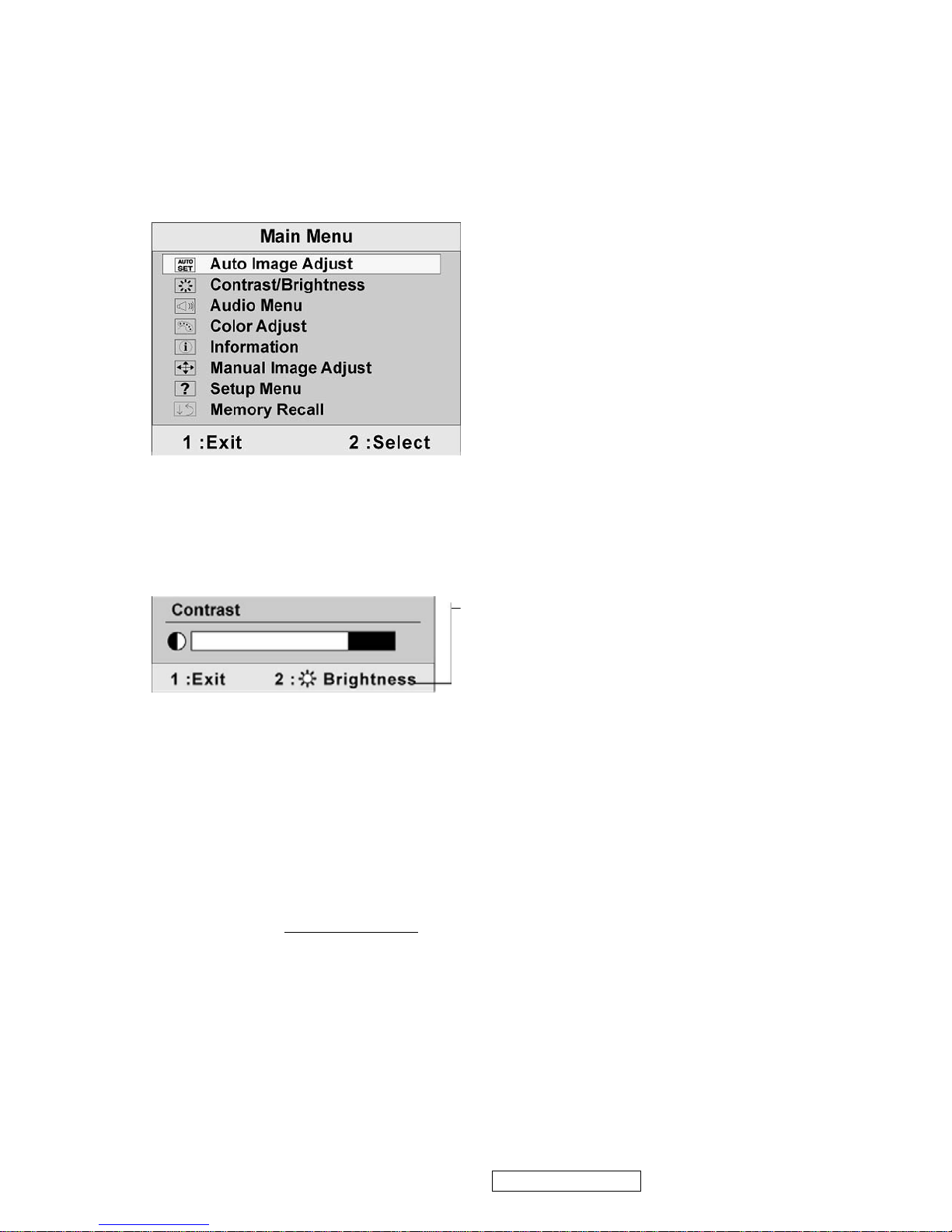
1. To display the Main Menu, press button [1].
NOTE: All OSD menus and adjustment screens disappear automatically after about 15
seconds. This is adjustable through the OSD timeout setting in the setup menu.
2. To select a control to adjust, press ▲or ▼ to scroll up or down in the Main Menu.
3. After the desired control is selected, press button [2]. A control screen like the one
shown below appears.
The line at the bottom of the screen shows the
current functions of buttons 1 and 2: Exit or
select the Brightness control.
4. To adjust the control, press the up ▲ or▼ down T buttons.
5. To save the adjustments and exit the menu, press button [1] twice.
The following tips may help you optimize your display:
• Adjust the computer's graphics card so that it outputs a 1024 x 768 @ 60Hz video
signal to the LCD display. (Look for instructions on “changing the refresh rate” in the
graphics card's user guide.)
• If necessary, make small adjustments using H. POSITION and V. POSITION until the
screen image is completely visible
. (The black border around the edge of the screen
should barely touch the illuminated “active area” of the LCD display.)
ViewSonic Corporation VA503b-1_ VA503m-1
14
Confidential - Do Not Copy
Page 18
Audio Adjust(For VA503m only)
Volume increases the volume, decreases the volume, and mutes the audio.
Mute temporarily silences audio output.
ViewSonic Corporation VA503b-1_ VA503m-1
15
Confidential - Do Not Copy
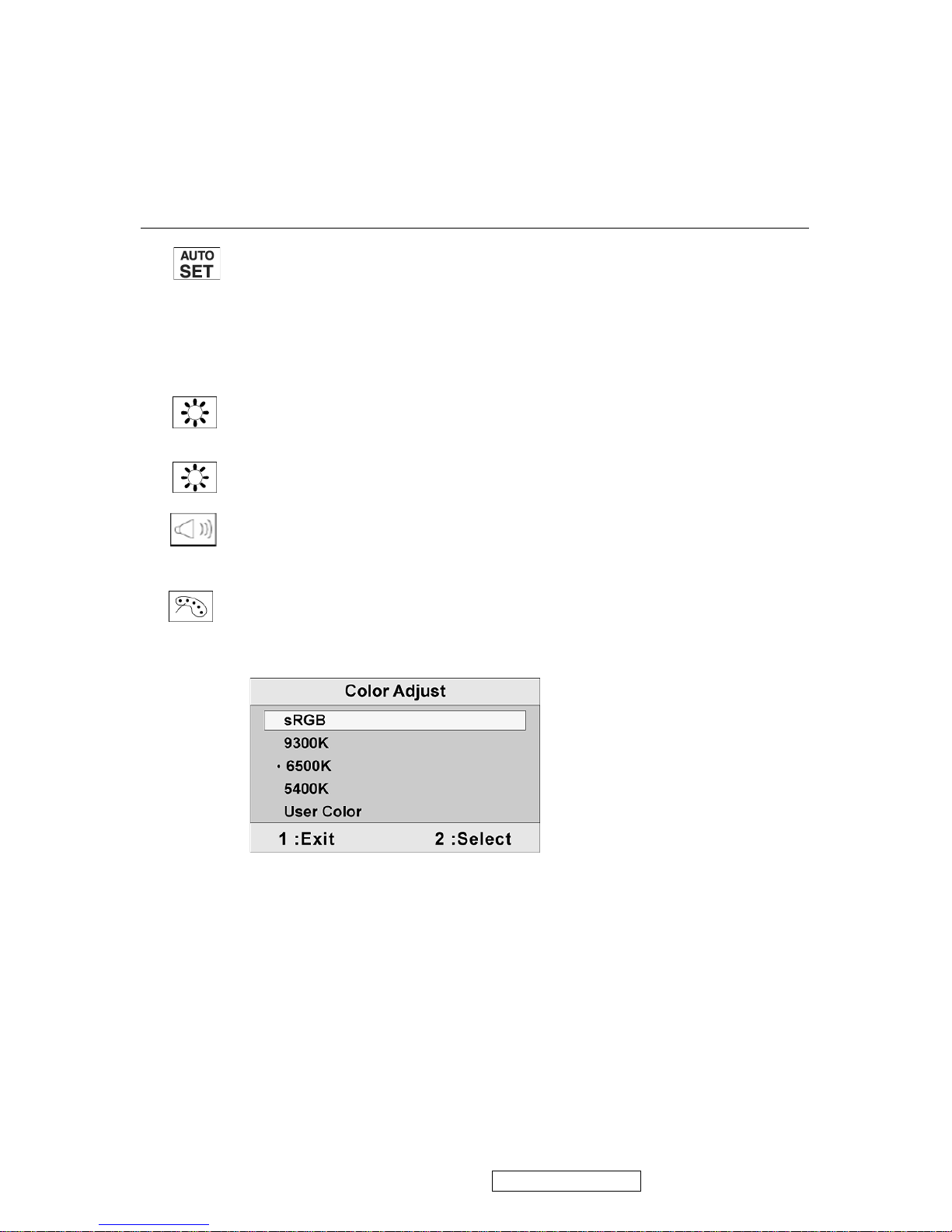
Color Adjust provides several color adjustment modes, including preset color
temperatures and a User Color mode which allows independent adjustment of
red (R), green (G), and blue (B). The factory setting for this product is 6500K
(6500 Kelvin).
sRGB-This is quickly becoming the industry standard for color management,
with support being included in many of the latest applications. Enabling this
setting allows the LCD display to more accurately display colors the way they
were originally intended. Enabling the sRGB setting will cause the Contrast and
Brightness adjustments to be disabled.
9300K-Adds blue to the screen image for cooler white (used in most office
settings with fluorescent lighting).
6500K-Adds red to the screen image for warmer white and richer red.
5400K-Adds green to the screen image for a darker color.
Main Menu Controls
Adjust the menu items shown below by using the up S and down T buttons.
Control Explanation
Auto Image Adjust automatically sizes, centers, and fine tunes the video signal
to eliminate waviness and distortion. Press the [2] button to obtain a sharper
image.
NOTE: Auto Image Adjust works with most common video cards. If this
function does not work on your LCD display, then lower the video refresh rate
to 60 Hz and set the resolution to its pre-set value.
Contrast adjusts the difference between the image background (black level)
and the foreground (white level).
Brightness adjusts background black level of the screen image.
Page 19
ViewSonic Corporation VA503b-1_ VA503m-1
16
Confidential - Do Not Copy
Control Explanation
User Color Individual adjustments for red (R), green (G), and blue (B).
1. To select color (R, G or B) press button [2].
2. To adjust selected color, pressSandT.
Important: If you select RECALL from the Main Menu when the product is
set to a Preset Timing Mode, colors return to the 6500K factory preset.
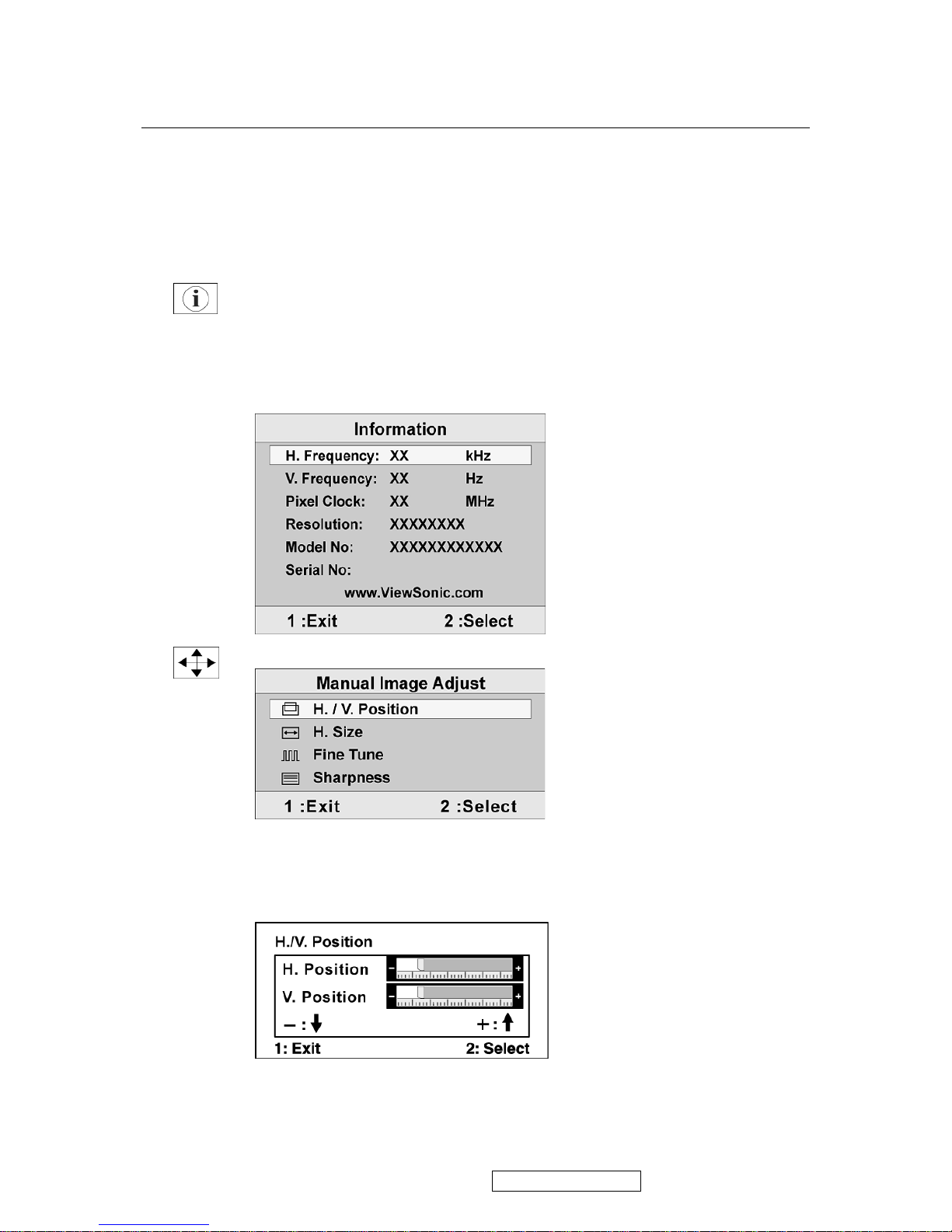
Information displays the timing mode (video signal input) coming from the
graphics card in the computer, the LCD model number, the serial number, and
the ViewSonic® website URL. See your graphics card’s user guide for
instructions on changing the resolution and refresh rate (vertical frequency).
NOTE: VESA 1024 x 768 @ 60Hz (recommended) means that the resolution is
1024 x 768 and the refresh rate is 60 Hertz.
Manual Image Adjust displays the Manual Image Adjust menu.
H. Size (Horizontal Size) adjusts the width of the screen image.
H./V. Position (Horizontal/Vertical Position) moves the screen image left or
right and up or down.
Page 20
ViewSonic Corporation VA503b-1_ VA503m-1
17
Confidential - Do Not Copy
Control Explanation
Fine Tune sharpens the focus by aligning text and/or graphics with pixel
boundaries.
NOTE: Try Auto Image Adjust first.
Sharpness adjusts the clarity and focus of the screen image.
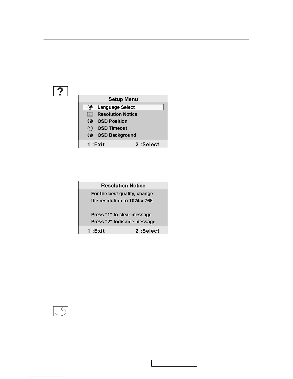
Setup Menu displays the menu shown below:
Language Select allows the user to choose the language used in the menus and
control screens.
Resolution Notice displays the Resolution Notice menu shown below.
Resolution Notice advises the optimal resolution to use.
OSD Position allows the user to move the OSD menus and control screens.
OSD Timeout sets the length of time the OSD screen is displayed. For example,
with a “15 second” setting, if a control is not pushed within 15 seconds, the
display screen disappears.
OSD Background allows the user to turn the OSD background On or Off.
Memory Recall returns the adjustments back to factory settings if the display is
operating in a factory Preset Timing Mode listed in the Specifications of this
manual.
Exception: This control does not affect changes made with the User Color
control, Language Select or Power Lock setting.
Page 21
SHORT CUTS FUNCTION FROM THE BUTTONS
[1]
Main Menu
[2]
Auto Image Adjust
[▼] or [▲]
To immediately activate Contrast menu. It should be
change to Brightness OSD by push button [2]
[▼] + [▲]
recall both of Contrast and Brightness to default
[1] + [2]
toggle 720x400 and 640x400 mode when input 720x400
or 640x400 mode
[1] + [▼] + [▲]
(keep pushing 5 sec)
White Balance (Not shown on user’s guide)
[1] + [▼]
Power Lock
[1] + [▲]
OSD Lock
Remark : All the short cuts function are only available while OSD off
ViewSonic Corporation VA503b-1_ VA503m-1
18
Confidential - Do Not Copy
Page 22
ViewSonic Corporation VA503b-1_ VA503m-1
19
4. Circuit Description
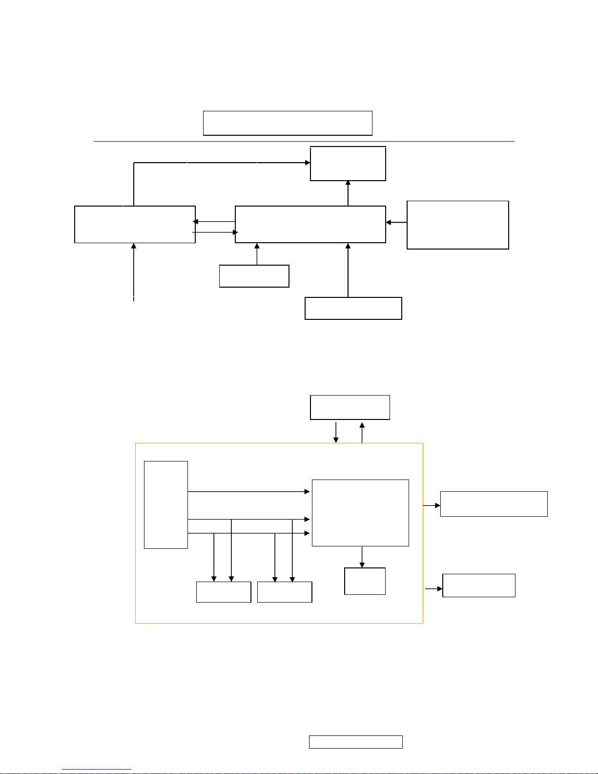
4.1 LCD MONITOR DESCRIPTION
The LCD MONITOR will contain a Main Board, an Power Board, Key Board which
house the flat panel control logic, brightness control logic and DDC.
4.2 MAIN BOARD BLOCK FUNCTION DESCRIPTION
The main board contains panel control logic, brightness control logic, DDC and DC
convert DC circuit and so on.
Power Board
(Include: adapter, inverter)
Flat Panel and
CCFL backlight
Main Board
Key Board
RS232 Connector
For white balance
adjustment in factory
mode
HOST Computer
CCFL Drive.
AC-IN
100V-240V
Video signal, DDC
Monitor Block Diagram
R
G
B
H
V
SDA
SCL
OSC
Backlight and Panel
PWPC board
EPROM EPROM
Keyboard
TSUM16AK
Confidential - Do Not Copy
Page 23
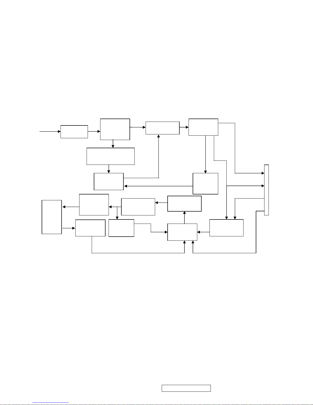
4.3 PWPC BOARD BLOCK FUNCTION DESCRIPTION
PWPC board combines to adapter and inverter, Adapter which commonly consists
of bridge rectifier and filter, start circuit, PWM control circuit, protection circuits and
convert to 12V, 5V DC voltage by input 90V-240V AC voltage that provide power supply
for each chips in the main board and inverter. Inverter is DC TO AC circuit. It changes
the 12v DC of power supply to about 600-800v AC that drives the backlight. It mostly
consists of starting circuit, PWM controller, DC changing circuit, LC surging circuit,
output circuit and protection circuit etc.
AC input
EMI filter
Bridge
Rectifier
and Filter
Start Circuit
R903, R904,R905
PWM
Control IC
Over
Voltage
Protect
Rectifier
CMOS
ON/OFF
Control
PWM
Control IC
Feedback
Circuit
OSC and
Output
Circuit
DC Convert
Circuit
MOSFET
Q203
Over
Voltage
CN902
Transformer
Lamp
5V
12V
ON/OF
DIM
ViewSonic Corporation VA503b-1_ VA503m-1
20
Confidential - Do Not Copy
Page 24
4.4 INTRODUCTION OF IC
STUM16AK(U401): integrate ADC, OSD, SCALER, MCU, LVDS, convert analog RGB
into digital and room and shrink scaling output to LCD panel.
PIN Function:
AIC1084-33PM (U702): DC power convert, used to 5v convert 3.3v.
LT1117-18(U701): DC power convert, used to 5v convert 3.3v.
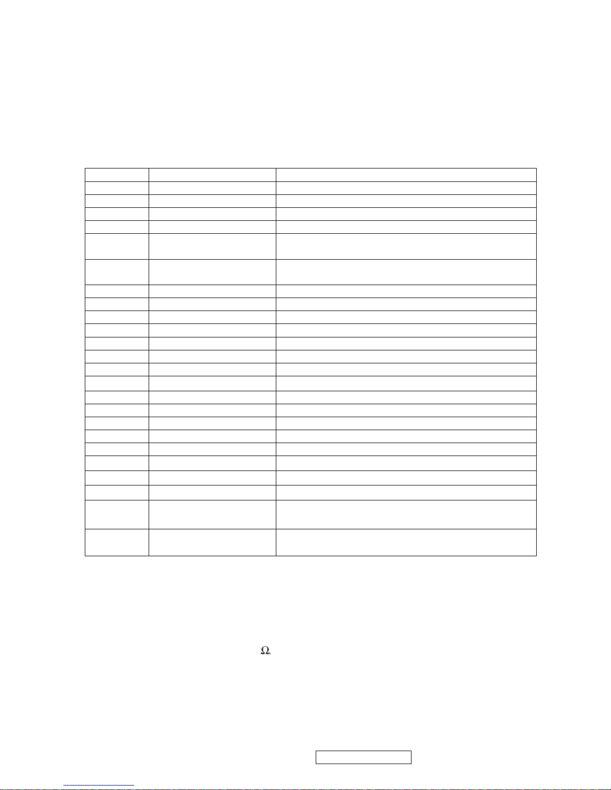
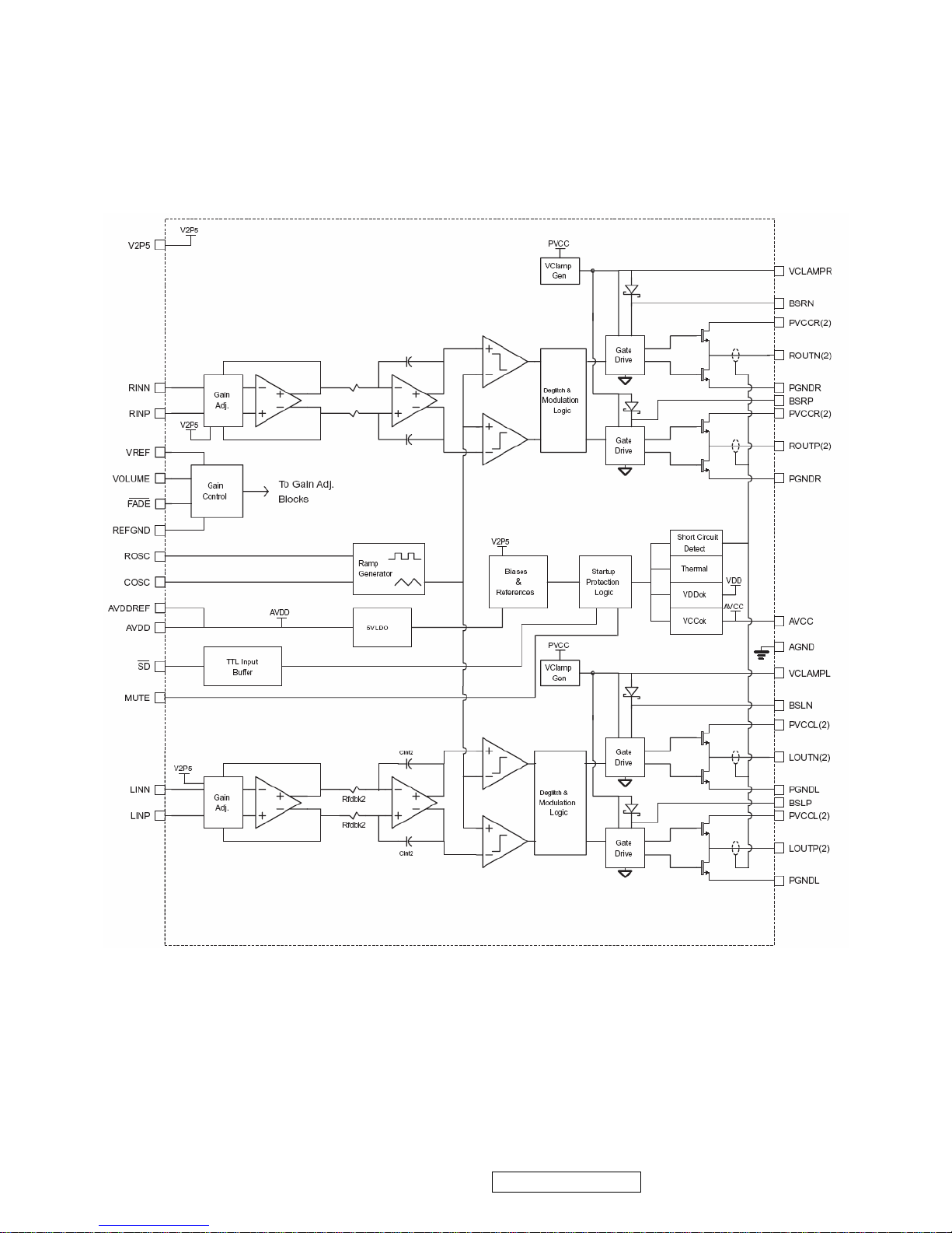
TPA3003D2 (U601): The TPA3003D2 is a audio amplifier IC,3-W efficient, driving
speakers as low as 8
, range of gain from -40dB to 36 dB. The function of
each pin and the inside circuit diagram are as follows:
Pin Symbol Description
70 SDO SPI flash serial data output; Input w/5V-tolerant
71 CSZ SPI flash chip select; output
72 SCK SPI flash serial select; output
73 SDI SPI flash serial data input; output
65 DDCA_SDA/RS232_TX DDC data for analog interface; 4mA driving
strength/UART transmitter/GPIO; I/O w/5V-tolrant
66 DDCA_SDA/RS232_RX DDC data for analog interface/UART
transmitter/GPIO;Input w/5V-tolrant
19 RST Chip reset; High reset; Input w/5V-tolerant
22 RSTN Chip reset; Low reset; Input w/5W-toerant
11 VCTRL Regulator control; Output
63 HSYNCO Analog HSYNC input
64 VSYNCO Analog VSYNC input
62 REFP Internal ADC top de-coupling pin
61 REFM Internal ADC bottom de-coupling pin
51 REXT
External resistor 390 ohm to AVDD_ADC
21 PWM1 PWM1; 4mA driving strength; Output
29 PWM0 PWM0; 4mA driving strength; Output
4 BYPASS For External Bypass Capacitor
32 XIN Xin; Crystal Oscillator Input
33 XOUT Xout; Crystal Oscillator Output
44、50、60 AVDD_ADC
ADC Power 3.3V
52
AVDD_PLL
PLL Power 3.3V
34
AVDD_MPLL
MPLL Power 3.3V
14、67、95、
103、115
VDDP Digital Output Power 3.3V
12、68、97、
117
VDDC Digital Core Power 1.8V
ViewSonic Corporation VA503b-1_ VA503m-1
21
Confidential - Do Not Copy
Page 25
Circuit Diagram
ViewSonic Corporation VA503b-1_ VA503m-1
22
Confidential - Do Not Copy
Page 26
PIN Function
TERMINAL
NO. NAME
I/O DESCRIPTION
AGND 9,10,26 -
Analog ground for digital/an alog cells in core
AVcc 33 -
High-voltage analog power supply (8.5V to 14V)
AVDD 29 O
5-V Regulated output
AVDDREF 7 O
5-V Reference output-provided for connection to adjacent VREF terminal.
BSLN 13 I/O
Bootstrap I/O for left channel, negative high-side FET
BSLP 24 I/O
Bootstrap I/O for left channel, positive high-side FET
BSRN 48 I/O
Bootstrap I/O for right channel, negative high-side FET
BSRP 37 I/O
Bootstrap I/O for right channel, positive high-side FET
COSC 28 I/O
I/O for charge/discharging currents onto capacitor for ramp generator triangle wave
biased at V2P5
FADE 30 I
Input for controlling volume ramp rate when cycling SD or during power-up. A logic
low on this pin places the amplifier in fade mode. A logic
high on this pin allows a quick transition to the desired volume setting.
LINN 6 I
Negative differential audio input for left channel
LINP 5 I
Positive differential audio input for left channel
LOUTN 16,17 O
Class-D 1/2-H-bridge negative output for left channel
LOUTP 20,21 O
Class-D 1/2-H-bridge positive output for left channel
MUTE 34 I
A logic high on this pin di sables the outputs. A low on this pin enables the outputs.
NC 31,32,35 -
Not internally connected
PGNDL 18,19 -
Power ground for left channel H-bridge
PGNDR 42,43 -
Power ground for right channel H-bridge
PVVCCL 14,15 -
Power supply for left channel H-bridge(tied to pins 22 and 23 internally), not
connected to PVCCR or AVcc
PVVCCL 22,23 -
Power supply for left channel H-bridge(tied to pins 14 and 15 internally), not
connected to PVCCR or AVcc
PVCCR 38,39 -
Power supply for right channel H-bridge(tied to pins 46 and 47 internally), not
connected to PVCCL or AVcc
PVCCR 46,47 -
Power supply for right channel H-bridge(tied to pins 38 and 39 internally), not
connected to PVCCL or AVcc
REFGND 12 -
Ground for gain control circuitry. Connect to AGND. If using a DAC to control the
volume, connect the DAC ground to this terminal.
RINP 3 I
Positive differential audio input for right channel
RINN 2 I
Negative differential audio input for right channel
ROSC 27 I/O
Current setting resistor for ramp generator. Nominally equal to 1/8*Vcc
ROUTN 44,45 O
Class-D 1/2-H-bridge negative output for right channel
ROUTP 40,41 O
Class-D 1/2-H-bridge positive output for right channel
SD 1 I
Shutdown signal for IC (low=shutdown, high=operational). TTL logic levels with
compliance to Vcc.
VCLAMPL 25 -
Internally generated voltage supply for left channel bootstrap capacitors.
VCLAMPR 36 -
Internally generated voltage supply for right channel bootstrap capacitors.
VOLUME 11 I
DC voltage that sets the gain of the amplifier.
VREF 8 I
Analog reference for gain control section.
V2P5 4 O
2.5-V Reference for analog cells, as well as reference for unused audio input when
using single-ended inputs.
ViewSonic Corporation VA503b-1_ VA503m-1
23
Confidential - Do Not Copy
Page 27

NCP1203D60R2G (IC901): PWM control, high-voltage startup current. The circuit unit
has functions such as over-current protection, over-voltage protection, output
short-circuit protection and etc. The function of each pin and the inside circuit diagram
are as follows:
Pin
No.
Pin
Name
Function Pin Description
1 Adj
Adjust the skipping
peak current
This pin lets you adjust the level at which the cycle
skipping process takes place. Shorting this pin to ground,
permanently disables the skip cycle feature.
2 FB
Sets the peak
current setpoint
By connecting an optocoupler to this pin, the peak current
setpoint is adjusted accordingly to the output power
demand. Skip cycle occurs when FB falls below Vpin1.
3 CS Current sense input
This pin senses the primary current and routes it to the
internal comparator via an L.E.B.
4 GND The IC ground −
5 Drv Driving pulses The driver’s output to an external MOSFET.
6 VCC Supplies the IC
This pin is connected to an external bulk capacitor of
typically 22 F.
7 NC −
This unconnected pin ensures adequate creepage
distance.
8 HV
Ensure a clean and
lossless startup
sequence
Connected to the high−voltage rail, this pin injects a
constant current into the VCC capacitor during the startup
sequence.
ViewSonic Corporation VA503b-1_ VA503m-1
24
Confidential - Do Not Copy
Page 28

TL1451 (IC201): PWM control, voltage range for working: 3.6~35V, Has such functions
as short-voltage protection, Over-voltage protection, over-current protection and
etc. The function of each pin and the circuit diagram inside are as follows:
Pin Symbol Description Pin Symbol Description
1 CT External timing capacitor 9 VCC Power supply
2 RT External timing resistor 10 2OUT Output 2
3 1IN+ Positive input for error amplifier 1 11 2DTC Output 2 dead time/soft start setting
4 1IN- Positive input for error amplifier 2 12 2FBK Error amplifier 2 output
5 1FBK Error amplifier 1 output 13 2IN+ Positive input for error amplifier
6 1DTC
Output 1 dead time/soft start
setting
14 2IN- Positive input for error amplifier
7 1OUT Output 1 15 SCP Timing latch setting
8 GND Ground 16 REF Reference voltage output (2.5v)
ViewSonic Corporation VA503b-1_ VA503m-1
25
Confidential - Do Not Copy
Page 29

ViewSonic Corporation VA503b-1_ VA503m-1
26
5. Adjustment Procedure
5.1 ADJUSTMENT CONDITIONS AND PRECAUTIONS
1. Approximately 30 minutes should be allowed for warm up before proceeding.
2. Adjustments should be undertaken only on those necessary elements since most of them
have been carefully preset at the factory.
3. ESD protection is needed before adjustment.
5.2 MAIN ADJUSTMENTS
NO. FUNCTIONS DESIGNATION
1. White Balance Function Key
2. Geometry Function Key
5.3 ALIGNMENT PROCEDURES
Approximately 30 minutes should be allowed for warm up before proceeding
White-Balance adjustment.
1. Adjust of White Balance
1.)How to do the Chroma-7120 MEM .Channel setting
A、Reference to chroma 7120 user guide
B、Use “ SC” key and “ NEXT” key to modify xyY value and use “ID” key to modify the
TEXT description Following is the procedure to do white-balance adjust
2.)Setting the color temp. You want
A、MEM.CHANNEL9 ( 9300 color):
9300 color temp. parameter is Wx = 0.283 ±0.03;Wy = 0.298 ±0.03;
Y = 250 ±20 cd/m
2 ,
B、MEM.CHANNEL10 ( 6500 color):
6500 color temp. parameter is Wx = 0.313±0.03;Wy = 0.329 ±0.03;
Y = 260 ±20 cd/m
2,
C、MEM.CHANNEL 11 ( 5400 color):
5400 color temp. parameter is Wx = 0.335±0.03;Wy = 0.350 ±0.03;
Y = 250 ±20 cd/m
2,
D、MEM.CHANNEL10 ( SRGB color):
6500 color temp. parameter is Wx = 0.313±0.03;Wy = 0.329 ±0.03;
Y = 220 ±20 cd/m
2,
Confidential - Do Not Copy
Page 30

3.)Into factory mode of VA503b/VA503m
A、First Power off, then press Switch 2 button along with press Power button will activate
the factory mode, then MCU will do AUTO LEVEL automatically. Meanwhile press
MENU the OSD screen will located at LEFT TOP OF PANEL.
4.)Bias adjustment :
Set the Contrast
to 70
Adjust the Brightness
to 100.
5.)Gain adjustment :
Move cursor to “-F-” and press MENU key
A、Adjust 9300 color-temperature
(1)、Switch the Chroma-7120 to RGB-Mode (with press “MODE” button )
(2)、Switch the MEM. channel to Channel 9 ( with up or down arrow on chroma 7120 )
(3)、The LCD-indicator on chroma 7120 will show x = 0.283 ±0.03, y =0.298 ±0.03,
Y = 250 ±20 cd/m
2
(4)、Adjust the RED of color1 on factory window until chroma 7120 indicator reached
the value R=100
(5)、Adjust the GREEN of color1 on factory window until chroma 7120 indicator reached
the value G=100
(6)、Adjust the BLUE of color1 on factory window until chroma 7120 indicator reached
the value B=100
(7)、Repeat above procedure ( item 4,5,6) until chroma 7120 RGB value meet the
tolerance =100±5
B、Adjust 6500 color-temperature
(1)、Switch the chroma-7120 to RGB-Mode (with press “MODE” button )
(2)、Switch the MEM .channel to Channel 10( with up or down arrow on chroma 7120 )
(3)、The LCD-indicator on chroma 7120 will show x = 0.313 ±0.03, y = 0.329 ±0.03, Y =
260 ±20 cd/m
2
(4)、Adjust the RED of color3 on factory window until chroma 7120 indicator reached
the value R=100
(5)、Adjust the GREEN of color3 on factory window until chroma 7120 indicator reached
the value G=100
(6)、Adjust the BLUE of color3 on factory window until chroma 7120 indicator reached
the value B=100
(7)、Repeat above procedure ( item 4,5,6) until chroma 7120 RGB value meet the
tolerance =100±5
ViewSonic Corporation VA503b-1_ VA503m-1
27
Confidential - Do Not Copy
Page 31

C、Adjust 5400 color-temperature
(1) Switch the chroma-7120 to RGB-Mode (with press “MODE” button )
(2)、Switch the MEM .channel to Channel 11( with up or down arrow on chroma 7120 )
(3)、The LCD-indicator on chroma 7120 will show x = 0.335 ±0.03, y = 0.350 ±0.03, Y =
250 ±20 cd/m
2
(4)、Adjust the RED of color3 on factory window until chroma 7120 indicator reached the
value R=100
(5)、Adjust the GREEN of color3 on factory window until chroma 7120 indicator reached
the value G=100
(6)、Adjust the BLUE of color3 on factory window until chroma 7120 indicator reached
the value B=100
(7)、Repeat above procedure ( item 4,5,6) until chroma 7120 RGB value meet the
tolerance =100±5
D、Adjust SRGB color-temperature
(1)、Switch the chroma-7120 to RGB-Mode (with press “MODE” button )
(2)、Switch the MEM .channel to Channel 10( with up or down arrow on chroma 7120 )
(3)、The LCD-indicator on chroma 7120 will show x = 0.313 ±0.03, y = 0.329 ±0.03, Y =
220 ±20 cd/m
2
(4)、Adjust the RED of color3 on factory window until chroma 7120 indicator reached
the value R=100
(5)、Adjust the GREEN of color3 on factory window until chroma 7120 indicator reached
the value G=100
(6)、Adjust the BLUE of color3 on factory window until chroma 7120 indicator reached
the value B=100
(7)、Repeat above procedure ( item 4,5,6) until chroma 7120 RGB value meet the
tolerance =100±5
E、Press reset key and Turn the Power-button “off to on” to quit from factory mode.
2. Geometry
1).Set cross-hatch pattern and preset timing as timing table listed.
2).Change to each mode in turn and wait for the monitor finish auto-alignment and save
press before change to next mode.
3).Until all of modes are adjusted,exit OSD menu and press POWER OFF to exit factory
mode.
ViewSonic Corporation VA503b-1_ VA503m-1
28
Confidential - Do Not Copy
Page 32

5.4 Factory Defaults
Item Defaults Item Defaults
Contrast 70% Volume 50%
(For VA503m only)
Brightness 100% Balance N/A
Color Temperature 6500K Treble N/A
Sharpness 0% Bass N/A
OSD H. Position 50% 720x400/640x400 720x400
OSD V. Position 50% 640x480@60Hz
720x480@60Hz
640x480@60Hz
OSD Time Out 15 Sec In SOG and Composite,
720x480@60Hz
640x480@60Hz
N/A
OSD Background Enabled In SOG and Composite,
1152x864@75Hz
1152x870@75Hz
N/A
Resolution Notice Enabled In SOG and Composite,
1280x768@60/75/85Hz
1024x768@60/75/85Hz
N/A
5.5 Function Test
1 Product: 17” LCD Monitor
2 Test Equipment: Color Video Signal & Pattern (or PC with SXGA resolution and a
sound card)
3 Test Condition: Before function test and alignment, each LCD Monitor should be
warmed up for at least 30 minutes with the following conditions:
(a)In room temperature,
(b) With full-white screen, RGB, and Black
(c) With cycled display modes,
640*480 (H=43.27kHz, V=85Hz)
800*600 (H=53.7kHz, V=85Hz)
1024*768 (H=68.67kHz, V=85Hz)
4 Test Display Modes & Pattern
Compatible Modes
Item Timing Analog
1 640 x 350 @ 70Hz, 31.5kHz
Yes
2 640 x 400 @ 70Hz
Yes
3 640 x 480 @ 50Hz
Yes
4 640 x 480 @ 60Hz, 31.5kHz
Yes
5 640 x 480 @ 67Hz, 35.0kHz
Yes
6 640 x 480 @ 72Hz, 37.9kHz
Yes
7 640 x 480 @ 75Hz, 37.5kHz
Yes
8 640 x 480 @ 85Hz, 43.27kHz
Yes
9 720 x 400 @ 70Hz, 31.5kHz
Yes
10 800 x 600 @ 56Hz, 35.1kHz
Yes
ViewSonic Corporation VA503b-1_ VA503m-1
29
Confidential - Do Not Copy
Page 33

1 1 800 x 600 @ 60Hz, 37.9kHz
Yes
12 800 x 600 @ 72Hz, 48.1kHz
Yes
13 800 x 600 @ 75Hz, 46.9kHz
Yes
14 800 x 600 @ 85Hz, 53.7kHz
Yes
15 832 x 624 @ 75Hz, 49.7kHz
Yes
16 1024 x 768 @ 60Hz, 48.4kHz Yes
17 1024 x 768 @ 70Hz, 56.5kHz
Yes
18 1024 x 768 @ 72Hz, 58.1kHz
Yes
19 1024 x 768 @ 75Hz, 60.0kHz
Yes
Function Test Display Pattern
Item Test Content Pattern Specification Remark
1
Frequency &
Tracking
Fine Line Moire
Eliminate visual wavy
noise.
Figure 1
2
Contrast/Bright
ness
16 Gray Scale
16 gray levels sh should
be distinguishable.
Figure 2
3 Boundary
Horizontal&Vertical
Thickness
Horizontal and Vertical
position of video should
be adjustable to be
within the screen frame.
Figure 3
4
RGB Color
Performance
RGB Color Intensities
Contrast of each R, G,
B, color should be
normal.
Figure
4,5,6
5
Screen
Uniformity &
Flicker
Full White
Should be compliant
with the spec.
Figure 7
6
Dead
Pixel/Line
White Screen & Dark
Screen
The numbers of dead
pixels should be
compliant with the spec.
Figure 7,8
7 White Balance White & Black Pattern
The screen must have
the pure white and black
pattern, no other color.
Figure 9
Fine Line Morie Pattern (Figure1) Gray Scale Pattern (Figure2)
ViewSonic Corporation VA503b-1_ VA503m-1
30
Confidential - Do Not Copy
Page 34

Horizontal & Vertical Thickness Pattern R. Color Pattern (Figure 4)
(Figure 3)
G. Color Pattern (Figure 5) B. Color Pattern (Figure 6)
Full White Pattern (Figure 7) Dark Screen Pattern (Figure 8)
ViewSonic Corporation VA503b-1_ VA503m-1
31
Confidential - Do Not Copy
Page 35

Black-White Pattern (Figure 9)
4.3 Function Test and Alignment Procedure
All Modes Reset
You should do “All Mode Reset” (Refer to Chapter III-3. Hot Keys for Function
Controls) first. This action will allow you to erase all end-user’s settings and restore
the factory defaults.
Auto Image Adjust
Please select and enter “Auto Image Adjust” function on Main Menu to see if it is
workable. The “Auto Image Adjust” function is aimed to offer a better screen quality
by built-in ASIC. For optimum screen quality, the user has to adjust each function
manually.
Firmware
Test Pattern: Burn In Mode (Refer to Chapter III-3. Hot Keys for Function Controls)
- Make sure the F/W is the latest version.
DDC
Test Pattern: EDID program
Make sure it can pass test program.
Fine Tune and Sharpness
Test Signal: 1024*768@60Hz
Test Pattern: Line Moire Pattern
Check and see if the image has noise and focus performs well. Eliminate visual
line bar.
If not, readjust by the following steps:
(a)Select and enter “Fine Tune” function on “Manual Image Adjust” to adjust the
image to eliminate visual wavy noise.
(b)Then, select and enter “Sharpness” function to adjust the clarity and focus of
the screen image.
Boundary
Test Signal: 1024*768@60Hz
Test Pattern: Horizontal & Vertical Line Thickness Pattern
Check and see if the image boundary is within the screen frame.
If not, readjust by the following steps:
(a)Select and enter “Manual Image Adjust” function on OSD Main Menu.
(b)Then, select and enter “Horizontal Size” or “Horizontal/Vertical Position” function
to adjust the video boundary to be full scanned and within screen frame.
ViewSonic Corporation VA503b-1_ VA503m-1
32
Confidential - Do Not Copy
Page 36

White Balance
Test Signal: 640*480@60Hz
Test Pattern: White and Black Pattern
1.5.8 R, G, B, Colors Contrast
Test Signal: 1024*768@60Hz
Test Pattern: R, G, B, Color Intensities Pattern and 16 Gray Scale Pattern
- Check and see if each color is normal and distinguishable.
- If not, please return the unit to repair area.
Screen Uniformity and Flicker
Test Signal: 1024*768@60Hz
Test Pattern: Full White Pattern
- Check and see if it is in normal condition.
1.5.10 Dead Pixel and Line
Test Signal: 1024*768@60Hz
Test Pattern: Dark and White Screen Pattern
- Check and see if there are dead pixels on LCD panel with shadow gauge and
filter film.
- The total numbers and distance of dead pixels should be compliant with the
spec.
Mura
Test Pattern: White, RGB, Black, & Grey
Test Tool: 10% ND Filter
- Check if the Mura can pass 10% ND Filter.
Audio
Test Signal: Voice signal (optional, depend on model)
Test Pattern: liberty
- Make sure there is audio output.
- Make sure that audio function (volume 80%) is working without noise and
resonance.
- Make sure that the sound of right and left speakers are in balance.
Check for Secondary Display Modes
Test Signal:
Analog: 640*350@70Hz; 640*480@60/67/72/75/85Hz;
720*400@70Hz; 800*600@56/60/72/75/85Hz;
832*624@75Hz, 1024*768@60/70/72/75/85Hz;
Digital: 640*350@70Hz; 640*480@60/72/75/85Hz;
720*400@70Hz; 800*600@56/60/72/75/85Hz;
1024*768@60/70/72/75/85Hz; 1152*870@75Hz,
- Normally when the primary mode 1024*768@60Hz is well adjusted and
compliant with the specification, the secondary display modes will also be
compliant with the spec. But we still have to check with the general test pattern to
make sure every secondary is compliant with the specification.
All Modes Reset
After final QC step, we have to erase all saved changes again and restore the
factory defaults. You should do “All Mode Reset” again.
Power Off Monitor
Turn off the monitor by pressing “Power” button.
ViewSonic Corporation VA503b-1_ VA503m-1
33
Confidential - Do Not Copy
Page 37

5.6 Firmware Upgrade Procedure
When you receive the returned monitor, please check whether the firmware version is
the latest. If not, please do the following procedures to upgrade it to the latest version.
1 Equipment Needed
- VA503/VA703/VA903 Monitor
- Fixture for Firmware Upgrade
- Power Adapter (P/N: 47.58201.001) *1 for Fixture
- VGA Cable (P/N: 42.59901.003) *1(Pin 4, 11 should be connected to GND)
- PC (Personal Computer)
- LPT Cable (P/N: 42.59906.001) *1
- Firmware Upgrade Program
- One additional monitor for checking the program execution
2 Setup Procedure
2.1 Connect P2 of Fixture with printer port of PC by LPT Cable.
2.2 Connect P1 of Fixture with VA503/VA703/VA903 Monitor by VGA Cable.
2.3 Plug Power Adapter to Fixture.
2.4 Connect Power Cord to VA503/VA703/VA903 Monitor.
ViewSonic Corporation VA503b-1_ VA503m-1
34
Confidential - Do Not Copy
Page 38

2.5 Connect P3 to the Signal Generator (eg.Chroma2326) for verifying it after the
operation being completed.
2.6 Connect PC to the additional monitor.
3 Firmware Upgrade Procedure
Step 1. Let VA503/VA703/VA903 set to be connected with AC cable and VGA cable.
Step 2.Execute the MSstar ISP tool.
Step 3. Click “Config” button . Select the Port Type: LPT1 and the Base Addr : 0x378
on “Communication Setting” flame, and then the Speed: 47 on “E2PROM Device
Setting” flame
P2:to LPT Cable
JP1:to Power Adapter
P1:to VGA Cable
P3:to Signal Generator
ViewSonic Corporation VA503b-1_ VA503m-1
35
Confidential - Do Not Copy
Page 39

Step 4. Click “Connect” button. (On this step, if the connection is successful, the “Entry
ISP Mode” Dialog will be showed. If not, the error dialog will be done.)
Step 5. Click “Device” button. Select the “PMC25LV010” or “SST25VF010” viewed on
your set.
Step 6. Click “Read” button. Select the object bincode on your corresponding directory.
ViewSonic Corporation VA503b-1_ VA503m-1
36
Confidential - Do Not Copy
Page 40

Step 7. Click “Auto” button. Execute the flashing action by clicking the “Run” button.
Step 8. If the flashing F/W has been completed, “Ok” message will be showed on the
right TextBox.
Step 9. Unplug and replug power cord of VA503/VA703/VA903 set and then check the
OSD operation and image on srceen.
ViewSonic Corporation VA503b-1_ VA503m-1
37
Confidential - Do Not Copy
Page 41

Step 10. At last, do “Memory Recall.”
3.2 Setup Procedure
3.2.1 Connect P2 and monitor of Fixture with VGA ports of VA503/VA703/VA903 by
VGA Cable.
3.2.2 Connect P1 of Fixture with Printer port of PC by LPT Cable.
3.2.3 Plug Power Adapter to Fixture.
3.2.4 Connect Power Cord to VA503/VA703/VA903 Monitor.
3.2.5 Connect PC to the additional monitor.
JP1: Power Adapter
P2: VGA Cable
P1:to LTP Cable
ViewSonic Corporation VA503b-1_ VA503m-1
38
Confidential - Do Not Copy
Page 42

3.3 DDC Key In Procedure
Sep1.Select and execute DDc Key In program
ViewSonic Corporation VA503b-1_ VA503m-1
39
Confidential - Do Not Copy
Page 43

Sep2:Inpute the S/N and execute “Enter”
ViewSonic Corporation VA503b-1_ VA503m-1
40
Confidential - Do Not Copy
Page 44

ViewSonic Corporation VA503b-1_ VA503m-1
41
Confidential - Do Not Copy
Page 45

Sep3:Key the “Enter” and write the data
ViewSonic Corporation VA503b-1_ VA503m-1
42
Confidential - Do Not Copy
Page 46

Sep4:If ddc program OK and show “data compare ok”
ViewSonic Corporation VA503b-1_ VA503m-1
43
Confidential - Do Not Copy
Page 47

Disassemble Process
1 Units Disassemble Process
1.1 Tools
Glove
Big cross screwdriver
Small cross screwdriver
Prize equipment or abandoned IC card
Screw box
Cushion
Six angle sleeve spanner
1.2 Disassemble process
1、 Tide up the worktable, spread straight cushion, put the monitor on it, the front side
adown.(Picture 1)
2、 Remove the decorate slice of the back cover.(Picture 2, 3)
3、 Disassemble the 4 screws that fix the stand, remove the stand..(Picture, 4)
4、 Disassemble the 4 screws of the back cover.(Picture 5)
5、 Use equipment or abandoned IC card to prize up the bezel through the bottom flute,
and rip up the bezel downwards.( as showed in the following the picture 6,7,8)
6、 Disassemble the 3 screws and 3 pins of the Key board, remove the Key board. ( as
showed in the following the picture 9,10)
7、 Remove the back cover, refer to the following picture 11.
8、 Disassemble the 3 fixed screw in the shield, remove the shield as the direction
arrowhead showed, refer to the following picture 12.
9、 Disassemble the 5 screws and 4 pins of the PWPC board, remove the PWPC
board.(symbolized the following picture 13 with red color)
10、 Disassemble the 2 screws and 4 pins of the audio board, remove the audio board.
(symbolized the following picture 13 with yellow color)
11、 Disassemble the 3 screws and 2 pins of the main board, remove the main board.
(symbolized the following picture 13,14 with blue color)
12、 Disassemble the 4 fixed screws of the panel, remove the main frame, as showed in
the following the picture 15,16,17. Do not damage the cable of the panel.
13
、 That’s all. The disassemble process of the unit is over.
ViewSonic Corporation VA503b-1_ VA503m-1
44
Confidential - Do Not Copy
Page 48

1.3 Show pictures:
(Picture 1) (Picture 2)
(Picture 3) (Picture 4)
(Picture 5) (Picture 6)
ViewSonic Corporation VA503b-1_ VA503m-1
45
Confidential - Do Not Copy
Page 49

(Picture 7) (Picture 8)
(Picture 9) (Picture 10)
(Picture 11) (Picture 12)
ViewSonic Corporation VA503b-1_ VA503m-1
46
Confidential - Do Not Copy
Page 50

(Picture 13)
(Picture 14)
(Picture 15)
(Picture 16)
ViewSonic Corporation VA503b-1_ VA503m-1
47
Confidential - Do Not Copy
Page 51

(Picture 17)
ViewSonic Corporation VA503b-1_ VA503m-1
48
Confidential - Do Not Copy
Page 52

First picture second picture third picture
fourth picture fifth picture sixth picture
seventh picture eighth picture ninth picture
Tenth picture
Packing Procedure
ViewSonic Corporation VA503b-1_ VA503m-1
49
Confidential - Do Not Copy
Page 53

ViewSonic Corporation VA503b-1_ VA503m-1
50
6. Troubleshooting Flow Chart
Confidential - Do Not Copy
Page 54

ViewSonic Corporation VA503b-1_ VA503m-1
51
7. Recommended Spare Parts List
Confidential - Do Not Copy
ViewSonic Model Number: VS11248
Rev: 1d
Serial No. Prefix: Q78
Item ECR/ECN ViewSonic P/N Ref. P/N Location Universal number#
1 Power Cord Added on 11/13/06 A-00003716 89G402A18N LS
2 Power Cord (EUROPE) A-00004962 89G404A18N LS
3 Power Cord (CHINA) A-00006663 89G414A18N LS
4 Power Cord (AP) Added on 07/31/06 A-00006703 89G420A18N IS
5 Key Board B-00005797 KEPC560KE1P
6 Power Cord B-00005798 PWPC1521HDV1P
7 Conversion Board Added on 07/31/06 B-00006704 CBPC561KH5VWP
8 Conversion Board Added on 11/13/06 B-00008194 CBPC560KV5VWP
9 Bezel C-00005799 34G1877B4Z B
10 Rear Cover C-00005800 34G1878 4Z 2B
11 Base C-00005821 34G1880 4Z B
12 Hinge Cover C-00006646 33G5020 4Z B
13 Wire Harness CB-00005801 95G8014 16701 X
14 Wire Harness Added on 07/31/06 CB-00006650 95G8018 24 16 Q
15 Signal Cable Added on 07/31/06 CB-00006702 89G 725HAA704
16 Carton Label DC-00003727 40G 459709 1B
17 H/V Warning Label DC-00003729 40G 459709 4A
18 Hg Label DC-00003730 40G457B709 1A
19 HI-POT Label For 17-LCD DC-00003731 40G 459709 5A
20 S/N Label DC-00005635 40G581B709 4A
21 Manual P/N Label DC-00005636 40G 58162435A
22 CD Manual DC-00005804 70G1501709 1A
23 Model Label DC-00005812 40G 45760819A
24 SPECIAL PAPER FOR CARTON/PALLET Added on 11/13/06 DC-00005813 40G 581 26704
25 QSG Added on 07/31/06 DC-00006645 J41G7801709 7B
26 ID Label Added on 11/13/06 DC-00008160 J40G 15T709 4A
27 Insert Card Added on 11/13/06 DC-00008161 J41G780170914A
28 CD Manual Added on 11/13/06 DC-00008162 J70G1501709 5A
29 IC M24C02-WMN6TP E-00003738 56G1133 34 U404
30 RESET_4.38V_G690H438T73U Added on 11/13/06 E-00003739 56G 643 20 U406
31 IC AP1084K33LA Added on 11/13/06 E-00004979 56G 563 21 U702
32 IC M24C16-WMN6TP E-00004982 56G1133 56 U403
33 AIC1084-33PM TO-263 E-00005651 56G 563 7 U702
34 TSUM16AK PQFP-128 IC E-00005806 56G 562100 U401
35 AIC1084-33PE TO-252 E-00005807 56G 563 25 U701
36 MAX810STRG SOT-23 IC E-00005808 56G 643 5A U406
37 Panel Added on 07/31/06 E-00006653 750GLH50X1732N000V
38 PM25LV010-25SCE Added on 07/31/06 E-00006711 56G1133 63 U402
39 LCD Module HSD150MX17-A02 Added on 10/9/06 E-00008092 750GLH50 X17-31N-000V
40 Integrated Circuit SG5841 VS-E060344 / Added on 10/27/06 E-00008126 56G 379 75 IC901
41 Resistance 12 k, SMD1206 VS-E060344 / Added on 10/27/06 E-00008127 61L1206123 R909
42 Resistance 220ohm SMD0805 VS-E060344 / Added on 10/27/06 E-00008128 61L0805221 R940
43 Resistance 0.47ohm VS-E060344 / Added on 10/27/06 E-00008129 61L153M47858F R919
44 Capacitance 470pF, MD0805 VS-E060344 / Added on 10/27/06 E-00008130 65G0805471 21 C940
45 Photo Coupler TCET1103G VS-E060344 / Added on 10/27/06 E-00008131 56G 139 5A IC902
46 Capacitance EUROP VS-E060344 / Added on 10/27/06 E-00008132 63G210J2242AC C213
47 Capacitance ARCO 0.22UF VS-E060344 / Added on 10/27/06 E-00008133 64G180J224AAT C213
48 IC GM6605-3.3TC3R TO-252 Added on 11/13/06 E-00008193 56G 563 78 U701
49 IC PM25LV010 Added on 11/13/06 E-00008194 56G1133 63 X U402
50 LCD Module SVA 150XG04TB Added on 11/13/06 E-00008195
750GLD504TB81N
51
Hardware:
Hinge HW-00005811 37G 481 1
52 Main Frame M-00005810 15G8935VSC 1
53 Main Frame Added on 11/13/06 M-00008051 J15G8935VSCSG3
54 Added on 07/31/06 E-00006651 J44G5001709 1C
Added on 08/21/06 P-00008046
55 PE Bag P-00005642 45G 76 28 V3
56 PE Bag for Base P-00005643 45G 88606
57 PE Bag P-00005644 45G 88607
58 EPS(L) P-00005817 J44G5001 1
59 EPS(R) P-00005818 J44G5001 2
60 Generic Foam Set P-00001345 31468
61 Generic Box P-00002513 20656
62
Plastics:
Stan
d
PL-00005820 34G1879 4Z B
Remark 1:
Above listed items are examples, supplier can expand the rows to add more necessary items.
Remark 2:
Cables: [All Cables]
Documentation:
Electronic
Components: [CRT-
EEPROM, Fly Back
Transformer,
Microprocessor]
[LCD TV-Panel]
Miscellaneous:
Packing Material:
[Box, Foam]
All revised RSPLs with newly added items or any change made should be highlighted and correlated with the ECN/ECR approved by ViewSonic Corporation. This is to
eliminate repeated cross checks of each item between this version and prior versions.
RECOMMENDED SPARE PARTS LIST (VA503B)
Description
Craft Box
Accessories:
[Adapter, Remote
Control]
PC Board Assembly:
[All PCBA]
Cabinets:
[Front Panel, Back
Cover, Base]
Page 55

Rev: 1d
Serial No. Prefix: Q79
Item ECR/ECN ViewSonic P/N Ref. P/N Location Universal number#
1
Power Cord (America)
A-00003716 89G402A18N LS
2
Power Cord
Added on 11/13/06 A-00004962 89G404A18N LS
3
Power Cord (China)
A-00006663 89G414A18N LS
4
Power Cord (AP)
A-00006703 89G420A18N IS
5
Audio Board
B-00005822 AUPC560B9P
6
Key Board
B-00005824 KEPC560KD9P
7
Power Board
B-00005825 PWPC1521HDV2P
8
Conversion Board
Added on 07/3106 B-00006659 CBPC561KH5VWAP
9
Conversion Board
Added on 11/13/06 B-00008196
CBPC560KV5VWAP
10
EPE Cover
C-00005816 45G 88609
11
Bezel
C-00005826 34G1877AKD B
12
Rear Cover
C-00005827 34G1878 KR 1B
13
Base
C-00005833 34G1880 KR B
14
Hinge Cover
Added on 07/3106 C-00006708 33G5020 KR B
15
Audio Cable
Added on 11/13/06 CB-00008078
89G 17356G554
16
Audio Cable
CB-00004972 89G 173 56 31
17
Wire Harness
CB-00005801 95G8014 16701 X
18
Wire Harness
CB-00006650 95G8018 24 16 Q
19
Signal Cable
CB-00006702 89G 725HAA704
20
Carton Label
DC-00003727 40G 459709 1B
21
H/V Warning Label
DC-00003729 40G 459709 4A
22
HG Label
DC-00003730 40G457B709 1A
23
HI-POT Label for 17-LCD
DC-00003731 40G 459709 5A
24
S/N Label
DC-00005635 40G581B709 4A
25
Manual P/N Label
DC-00005636 40G 58162435A
26
Model Label
DC-00005812 40G 45760819A
27
Special Paper for Carton/Pallet
DC-00005813 40G 581 26704
28
Pallet Label
DC-00005814 40G 58170918D
29
QSG
Added on 07/3106 DC-00006660 J41G7801709 8B
30
CD Manual
Added on 07/3106 DC-00006661 J70G1501709 2A
31
Insert Card
Added on 11/13/06 DC-00008161 J41G780170914A
32
ID Label
Added on 11/13/06 DC-00008165
J40G 15T709 3A
33
CD Manual
Added on 11/13/06 DC-00008166
J70G1501709 6A
34
IC M24C02-WMN6TP
E-00003738 56G1133 34 U404
35
RESET_4.38V_G690H438T73U
E-00003739 56G 643 20 U406
36
IC AP1084K33LA
Added on 11/13/06 E-00004979
56G 563 21
U702
37
IC M24C16-WMN6TP
E-00004982 56G1133 56 U403
38
AIC1084-33PM TO-263
E-00005651 56G 563 7 U702
39
TSUM16AK PQFP-128 IC
E-00005806 56G 562100 U401
40
AIC1084-33PE TO-252
E-00005807 56G 563 25 U701
41
Speaker
E-00005828 78G 455 1 K
42
Speaker
Added on 11/13/06 E-00005829
78G 455 1 Y
43
Panel
E-00006653 750GLH50X1732N000V
44
MAX810STRG SOT-23 IC
Added on 07/3106 E-00006706 56G 643 6 U406
45
PM25LV010-25SCE
E-00006711 56G1133 63 U402
46
LCD Module HSD150MX17-A02
Added on 10/9/06 E-00008092 750GLH50 X17-31N-000V
47
Integrated Circuit SG5841
VS-E060344 /
Added on 10/27/06
E-00008126 56G 379 75 IC901
48
Resistance 12 k, SMD1206
VS-E060344 /
Added on 10/27/06
E-00008127 61L1206123 R909
49
Resistance 220ohm SMD0805
VS-E060344 /
Added on 10/27/06
E-00008128 61L0805221 R940
50
Resistance 0.47ohm
VS-E060344 /
Added on 10/27/06
E-00008129 61L153M47858F R919
51
Capacitance 470pF, MD0805
VS-E060344 /
Added on 10/27/06
E-00008130 65G0805471 21 C940
52
Photo Coupler TCET1103G
VS-E060344 /
Added on 10/27/06
E-00008131 56G 139 5A IC902
53
Capacitance EUROP
VS-E060344 /
Added on 10/27/06
E-00008132 63G210J2242AC C213
54
Capacitance ARCO 0.22UF
VS-E060344 /
Added on 10/27/06
E-00008133 64G180J224AAT C213
55
GM6605-3.3TC3R TO-252
Added on 11/13/06 E-00008193
56G 563 78
U701
56
PM25LV010
Added on 11/13/06 E-00008194
56G1133 63 X
U402
57
LCD Module- SVA 150XG04TB
Added on 11/13/06 E-00008195
750GLD504TB81N
58
Hardware:
Hin
ge
HW-00005811 37G 481 1
59 Main Frame M-00005810 15G8935VSC 1
60 Main Frame Added on 11/13/06 M-00008051
J15G8935VSCSG3
61 PE Bag P-00005642 45G 76 28 V3
62 PE Bad for Base P-00005643 45G 88606
63 PE Bag P-00005644 45G 88607
64 EPS(L) P-00005817 J44G5001 1
65 EPS(R) P-00005818 J44G5001 2
66 Carton Label Added on 07/3106 P-00006707 J44G5001709 2C
67 Generic Foam Set P-00001345 31468
68 Generic Box P-00002513 20656
69
Plastics:
Stand PL-00005832 34G1879 KR B
Remark 1:
Remark 2:
Packing Material:
RECOMMENDED SPARE PARTS LIST (VA503M)
Accessories:
PC Board
Assembly:
All revised RSPLs with newly added items or any change made should be highlighted and correlated with the ECN/ECR approved by ViewSonic
Cor
p
oration. This is to eliminate repeated cross checks of each item between this version and prior version
s
Above listed items are examples, supplier can expand the rows to add more necessary items.
Description
Cabinets:
Cables:
Documentation:
Electronic
Components:
ViewSonic Model Number: VS1124
8
Miscellaneous:
ViewSonic Corporation VA503b-1_ VA503m-1
52
Confidential - Do Not Copy
Page 56

Rev: 1d
Serial No. Prefix: Q78
Item ViewSonic P/N Ref. P/N Description Location Universal number# Q'ty
1 B-00008194 CBPC560KV5VWP CONVERSION BOARD
1
2 B-00005797 KEPC560KE1P KEPC BOARD
1
3 B-00005798 PWPC1521HDV1P POWER BOARD
1
4 N/A 11G6055 1 SQUARE FRAME
2
5 N/A 12G 808 1 VESA RUBBER
4
6 N/A 15G5791 1 VESA BRACKET
1
7 N/A 15G5908 2 AC BRACKET
1
8 M-00008051 J15G8935VSCSG3 MAIN FRAME
1
9 N/A 23G3178709 6A BIRD LOGO (E015-006)
1
10 PL-00006485 33G5019 KD C FUNC.BUTTON
1
11 C-00006708 33G5020 KR B HINGE COVER
1
12 C-00005799 34G1877B4Z B BEZEL
1
13 C-00005800 34G1878 4Z 2B REAR COVER
1
14 PL-00005820 34G1879 4Z B STAND
1
15 C-00005821 34G1880 4Z B BASE
1
16 HW-00005811 37G 481 1 HINGE
1
17 DC-00005812 40G 45760819A MODEL LABEL
1
18 DC-00003727 40G 459709 1B CARTON LABEL
1
19 DC-00005635 40G581B709 4A S/N LABEL
1
20 DC-00003729 40G 459709 4A H/V WARNING LABEL
1
21 DC-00003731 40G 459709 5A HI-POT LABEL FOR 17-LCD
1
22 DC-00005636 40G 58162435A MANUAL P/N LABEL
1
23 DC-00003730 40G457B709 1A Hg LABEL
1
24 DC-00005635 40G581B709 4A S/N LABEL
2
25 P-00005642 45G 76 28 V3 PE BAG
1
26 N/A 45G 77 3 TRANSPARENT SHEET
173
27 P-00005643 45G 88606 PE BAG FOR BASE
1
28 P-00005644 45G 88607 PE BAG
1
29 N/A 50G 600 1 W WHITE PACKING TAPE
74
30 N/A J50G 600 5 HANDLE1
1
31 N/A J50G 600 6 HANDLE2
1
32 N/A 52G 1185 MIDDLE TAPE FOR CARTON
10
33 N/A 52G 1185 24 TAPE
65
34 N/A 52G 1207 A ALUMINUM-FOIL TAPE
1
35 N/A 52G 2191 D TAPE
75
36 N/A 52G6019 1 YELLOW TAPE
9
37 N/A 52G6020 2 PROTECT FILM
1
38 N/A 52G6025 11582 MYLAR SHIELD
1
39 N/A 52G6025 11731 INSULATE SHEET
1
40 N/A 52G6025 11791 MYLAR(AUDIO PCB)
1
41 N/A 78G 455 1 K/R SPEAKER
2
42 N/A 85G 645 1 NAREOM SHIELD
1
43 CB-00006702 89G 725HAA704 SIGNAL CABLE
1
44 N/A 89G402A18N LS(USA) POWER CORD
1
45 CB-00005801 95G8014 16701 X WIRE HARNESS
1
46 N/A 95G8018 24 16 Q WIRE HARNESS
1
47 N/A M1G 330 4128 CR3 SCREW FOR BRACKET
1
48 N/A M1G 330 4128 CR3 SCREW FOR BRACKET
4
49 N/A M1G 330 6 47 CR3 SCREW
4
50 N/A M1G1140 6128 CR3 SCREW
1
51 N/A M1G1730 6128 CR3 SCREW
4
52 N/A M1G1730 6128 CR3 SCREW
2
53 N/A M1G1730 6128 CR3 SCREW
3
54 N/A M1G1740 10 47 CR3 SCREW 4X10MM
4
55 N/A Q1G 140 10128 CR3 SCREW
3
56 N/A Q1G 330 6120 SCREW M3X6MM
3
57 E-00008195 750GLD504TB81N SVA150XG04TB REV:Q
1
58 N/A J12G 394800 FOOT
6
ViewSonic Model Number: VS11248
BOM LIST (VA503B)
ViewSonic Corporation VA503b-1_ VA503m-1
53
Confidential - Do Not Copy
Page 57

Item ViewSonic P/N Ref. P/N Description Location Universal number# Q'ty
59 DC-00008160 J40G 15T709 4A ID VA503M
1
60 P-00005817 J44G5001 1 EPS(L)
1
61 P-00005818 J44G5001 2 EPS(R)
1
62 P-00008046 J44G5001709 1C CARTON
1
63 DC-00006645 J41G7801709 7B QSG
1
64 DC-00008161 J41G780170914A INSERT CARD
1
65 DC-00008162 J70G1501709 5A CD MANUAL
1
ViewSonic Corporation VA503b-1_ VA503m-1
54
Confidential - Do Not Copy
Page 58

Rev: 1c
Serial No. Prefix: Q79
Item ViewSonic P/N Ref. P/N Description Location Universal number# Q'ty
1 B-00005822 AUPC560B9P AUDIO BOARD 1
2 B-00008196 CBPC560KV5VWAP CONVERSION BOARD 1
3 B-00005824 KEPC560KD9P KEPC BOARD 1
4 B-00005825 PWPC1521HDV2P POWER BOARD 1
5 N/A 11G6055 1 SQUARE FRAME 2
6 N/A 12G 808 1 VESA RUBBER 4
7 N/A 15G5791 1 VESA BRACKET 1
8 N/A 15G5908 2 AC BRACKET 1
9 M-00008051 J15G8935VSCSG3 MAIN FRAME 1
10 N/A 23G3178709 6A BIRD LOGO (E015-006) 1
11 PL-00006485 33G5019 KD C FUNC.BUTTON 1
12 C-00006708 33G5020 KR B HINGE COVER 1
13 C-00005826 34G1877AKD B BEZEL 1
14 C-00005827 34G1878 KR 1B REAR COVER 1
15 PL-00005832 34G1879 KR B STAND 1
16 C-00005833 34G1880 KR B BASE 1
17 HW-00005811 37G 481 1 HINGE 1
18 DC-00005812 40G 45760819A MODEL LABEL 1
19 DC-00003727 40G 459709 1B CARTON LABEL 1
20 DC-00005635 40G581B709 4A S/N LABEL 1
21 DC-00003729 40G 459709 4A H/V WARNING LABEL 1
22 DC-00003731 40G 459709 5A HI-POT LABEL FOR 17-LCD 1
23 DC-00005636 40G 58162435A MANUAL P/N LABEL 1
24 DC-00003730 40G457B709 1A Hg LABEL 1
25 DC-00005635 40G581B709 4A S/N LABEL 2
26 P-00005642 45G 76 28 V3 PE BAG 1
27 N/A 45G 77 3 TRANSPARENT SHEET 173
28 P-00005643 45G 88606 PE BAG FOR BASE 1
29 P-00005644 45G 88607 PE BAG 1
30 C-00005816 45G 88609 EPE COVER 1
31 N/A 50G 600 1 W WHITE PACKING TAPE 74
32 N/A J50G 600 5 HANDLE1 1
33 N/A J50G 600 6 HANDLE2 1
34 N/A 52G 1185 MIDDLE TAPE FOR CARTON 10
35 N/A 52G 1185 24 TAPE 65
36 N/A 52G 1207 A ALUMINUM-FOIL TAPE 1
37 N/A 52G 2191 D TAPE 75
38 N/A 52G6019 1 YELLOW TAPE 9
39 N/A 52G6020 2 PROTECT FILM 1
40 N/A 52G6025 11582 MYLAR SHIELD 1
41 N/A 52G6025 11731 INSULATE SHEET 1
42 N/A 52G6025 11791 MYLAR(AUDIO PCB) 1
43 N/A 78G 455 1 K/R SPEAKER 2
44 N/A 85G 645 1 NAREOM SHIELD 1
45 CB-00008078 89G 17356G554 AUDIO CABLE 1
46 CB-00006702 89G 725HAA704 SIGNAL CABLE 1
47 N/A 89G404A18N LS(EUROPE) POWER CORD 1
48 POWER CORD 1
49 CB-00005801 95G8014 16701 X WIRE HARNESS 1
50 N/A 95G8018 24 16 Q WIRE HARNESS 1
51 N/A M1G 330 4128 CR3 SCREW FOR BRACKET 1
52 N/A M1G 330 4128 CR3 SCREW FOR BRACKET 4
53 N/A M1G 330 6 47 CR3 SCREW 4
54 N/A M1G1140 6128 CR3 SCREW 1
55 N/A M1G1730 6128 CR3 SCREW 4
56 N/A M1G1730 6128 CR3 SCREW 2
57 N/A M1G1730 6128 CR3 SCREW 3
58 N/A M1G1740 10 47 CR3 SCREW 4X10MM 4
59 N/A Q1G 140 10128 CR3 SCREW 3
60 N/A Q1G 330 6120 SCREW M3X6MM 3
61 N/A 750GLD504TB81N SVA150XG04TB REV:Q 1
62 N/A J12G 394800 FOOT 6
63 N/A J40G 15T709 3A ID VA503M 1
64 DC-00006481 J40GSTAR709 1A EPA LABEL 1
65 P-00005817 J44G5001 1 EPS(L) 1
66 P-00005818 J44G5001 2 EPS(R) 1
67 P-00006707 J44G5001709 2C CARTON 1
ViewSonic Model Number: VS11248
BOM LIST (VA503M)
ViewSonic Corporation VA503b-1_ VA503m-1
55
Confidential - Do Not Copy
Page 59

Item ViewSonic P/N Ref. P/N Description Location Universal number# Q'ty
68 DC-00006660 J41G7801709 8B QSG 1
69 N/A J41G780170914A INSERT CARD 1
70 N/A J52G8001 9 NON-WOVEN FABRICS 4
71 N/A J52G8001 10 NON-WOVEN FABRICS 2
72 N/A J70G1501709 6A CD MANUAL
1
ViewSonic Corporation VA503b-1_ VA503m-1
56
Confidential - Do Not Copy
Page 60

8. Exploded Diagram and Exploded Parts List
ViewSonic Corporation VA503b-1_ VA503m-1
57
Confidential - Do Not Copy
(VA503b)
Page 61

ViewSonic Corporation VA503b-1_ VA503m-1
58
ViewSonic Model Number: VS11248
Rev: 1a
Serial No. Prefix: Q78
Item ViewSonic P/N Ref. P/N Description Q'ty
1 N/A 33G5019 KD C FUNC. BUTTON 1
2 C-00005799 34G1877B4Z B BEZEL 1
3 N/A 23G3178709 6A VSC LOGO 1
4 N/A KEPC560KD9P KEPC BOARD 1
5 N/A Q1G 330 6120 SCREW 3
6 N/A 750GLH9013A11N000V HSD190ME13 19" LCD PANEL 1
7 M-00005810 15G8935VSC 1 MIAN FRAME 1
8 N/A M1G 330 4120 SCREW 4
9 N/A 52G6025 11731 MYLAR 1
10 N/A PWPC1942HV1P POWER BOARD 1
11 N/A 52G6025 11582 MYLAR 1
12 N/A M1G1730 6120 SCREW 3
13 N/A CBPC980KH5VWAP CONVERSION 1
14 N/A M1G1730 6120 SCREW 4
15 N/A 85G645 1 SHIELD 1
16 N/A M1G330 4120 SCREW 1
17 N/A 15G5791 1 VESA BRACKET 1
18 N/A 34G1878 4Z 1B REAR COVER 1
19 N/A 12G808 1 VESA RUBBER 4
20 N/A M1G330 6 47 SCREW 4
21 N/A 33G5020 4Z B HINGE COVER 1
22 N/A 37G481 1 HINGE 1
23 PL-00005820 34G1879 4Z B STAND 1
24 C-00005821 34G1880 4Z B BASE 1
25 N/A 12G394800 PORON FOOT 6
26 N/A QIG140 10120 SCREW 3
27 N/A M1G740 10 47 SCREW 4
28 N/A M1G1140 6120 SCREW 4
EXPLODED PARTS LIST (VA503b-1)
Confidential - Do Not Copy
Page 62

ViewSonic Corporation VA503b-1_ VA503m-1
59
EXPLODED SPARE PARTS LIST (VA503b-1)
ViewSonic Model Number: VS11248
Rev: 1b
ITEM ViewSonic P/N Ref. P/N Description Qty
1 N/A 33G5019 KD C FUNC. BUTTON 1
2 N/A 34G1877B4Z B BEZEL 1
3 N/A 23G3178709 6A VSC LOGO 1
4 B-00005824 KEPC560KD9P KEPC BOARD 1
5 HW-00003750 Q1G 330 6120 SCREW 3
6 N/A 750GLH50X1731N000V HSD150MX17 15" LCD PANEL 1
7 N/A 15G8935VSC 1 MIAN FRAME 1
8 N/A M1G 330 4120 SCREW 4
9 N/A 52G6025 11731 MYLAR 1
10 B-00006463 PWPC1942HV1P POWER BOARD 1
11 N/A 52G6025 11582 MYLAR 1
12 N/A M1G1730 6120 SCREW 3
13 B-00006490 CBPC980KH5VWAP CONVERSION 1
14 N/A M1G1730 6120 SCREW 4
15 N/A 85G645 1 SHIELD 1
16 N/A M1G330 4120 SCREW 1
17 N/A 15G5791 1 VESA BRACKET 1
18 N/A 34G1878 4Z 1B REAR COVER 1
19 N/A 12G808 1 VESA RUBBER 4
20 N/A M1G330 6 47 SCREW 4
21 N/A 33G5020 4Z B HINGE COVER 1
22 N/A 37G481 1 HINGE 1
23 N/A 34G1879 4Z B STAND 1
24 N/A 34G1880 4Z B BASE 1
25 N/A 12G394800 PORON FOOT 6
26 N/A QIG140 10120 SCREW 3
27 N/A M1G740 10 47 SCREW 4
28 HW-00004991 M1G1140 6120 SCREW 4
Confidential - Do Not Copy
Page 63

ViewSonic Corporation VA503b-1_ VA503m-1
60
(VA503m)
Confidential - Do Not Copy
Page 64

ViewSonic Model Number: VS11248
Rev: 1a
Serial No. Prefix: Q79
Item ViewSonic P/N Ref. P/N Description Q'ty
1 N/A 33G5019 KD C FUNC. BUTTON 1
2 C-00005799 34G1877B4Z B BEZEL 1
3 N/A 23G3178709 6A VSC LOGO 1
4 B-00005824 KEPC560KD9P KEPC BOARD 1
5 N/A Q1G 330 6120 SCREW 3
6 N/A 750GLH9013A11N000V HSD190ME13 19" LCD PANEL 1
7 M-00005810 15G8935VSC 1 MIAN FRAME 1
8 N/A M1G 330 4120 SCREW 4
9 N/A 52G6025 11731 MYLAR 1
10 N/A PWPC1942HV1P POWER BOARD 1
11 N/A 52G6025 11582 MYLAR 1
12 N/A M1G1730 6120 SCREW 3
13 N/A CBPC980KH5VWAP CONVERSION 1
14 N/A M1G1730 6120 SCREW 4
15 N/A 85G645 1 SHIELD 1
16 N/A M1G330 4120 SCREW 1
17 N/A 15G5791 1 VESA BRACKET 1
18 N/A 34G1878 4Z 1B REAR COVER 1
19 N/A 12G808 1 VESA RUBBER 4
20 N/A M1G330 6 47 SCREW 4
21 N/A 33G5020 4Z B HINGE COVER 1
22 N/A 37G481 1 HINGE 1
23 PL-00005820 34G1879 4Z B STAND 1
24 C-00005821 34G1880 4Z B BASE 1
25 N/A 12G394800 PORON FOOT 6
26 N/A QIG140 10120 SCREW 3
27 N/A M1G740 10 47 SCREW 4
28 N/A M1G1140 6120 SCREW 4
29 N/A 78G 455 1 K/Y SPEAKER 2
30 B-00005822 AUPC560B9P AUDIO BOARD 1
31 N/A M1G1730 6120 SCREW 2
EXPLODED PARTS LIST (VA503m-1)
ViewSonic Corporation VA503b-1_ VA503m-1
61
Confidential - Do Not Copy
Page 65

Rev: 1b
Serial No. Prefix: Q79
ITEM ViewSonic P/N Ref. P/N Description Qty
1 N/A 33G5019 KD C FUNC. BUTTON 1
2 N/A 34G1877B4Z B BEZEL 1
3 N/A 23G3178709 6A VSC LOGO 1
4 B-00005824 KEPC560KD9P KEPC BOARD 1
5 HW-00003750 Q1G 330 6120 SCREW 3
6 N/A 750GLH50X1731N000V HSD150MX17 15" LCD PANEL 1
7 N/A 15G8935VSC 1 MIAN FRAME 1
8 N/A M1G 330 4120 SCREW 4
9 N/A 52G6025 11731 MYLAR 1
10 B-00006463 PWPC1942HV1P POWER BOARD 1
11 N/A 52G6025 11582 MYLAR 1
12 N/A M1G1730 6120 SCREW 3
13 B-00006490 CBPC980KH5VWAP CONVERSION 1
14 N/A M1G1730 6120 SCREW 4
15 N/A 85G645 1 SHIELD 1
16 N/A M1G330 4120 SCREW 1
17 N/A 15G5791 1 VESA BRACKET 1
18 N/A 34G1878 4Z 1B REAR COVER 1
19 N/A 12G808 1 VESA RUBBER 4
20 N/A M1G330 6 47 SCREW 4
21 N/A 33G5020 4Z B HINGE COVER 1
22 N/A 37G481 1 HINGE 1
23 N/A 34G1879 4Z B STAND 1
24 N/A 34G1880 4Z B BASE 1
25 N/A 12G394800 PORON FOOT 6
26 N/A QIG140 10120 SCREW 3
27 N/A M1G740 10 47 SCREW 4
28 HW-00004991 M1G1140 6120 SCREW 4
29 N/A 78G 455 1 K/Y SPEAKER 2
30 B-00005822 AUPC560B9P AUDIO BOARD 1
31 N/A M1G1730 6120 SCREW 2
ViewSonic Model Number: VS11248
EXPLODED SPARE PARTS LIST (VA503m-1)
ViewSonic Corporation VA503b-1_ VA503m-1
62
Confidential - Do Not Copy
Page 66

ViewSonic Corporation VA503b-1_ VA503m-1
63
Packing for Shipping (VA503b)
Confidential - Do Not Copy
Page 67

PACKING PARTS LIST (VA503b-1)
ViewSonic Model Number: VS11248
Rev: 1b
ITEM ViewSonic P/N Ref. P/N DESCRIPTION Q'TY
1 E-00006651 J44G5001709 1C CARTON 1
2 N/A 50G 600 2/3 HANDLE1/2 1
3 P-00005642 45G 76 28 V3 PE BAG 1
4 DC-00005804 70G1501709 1A CD MANUAL 1
5 DC-00006645 J41G7801709 7B QSG 1
6 P-00005643 45G 88606 EPE COVER 1
7 N/A T561KH5HTUVWNBP MONITOR 1
8 P-00005644 45G 88607 PE BAG 1
9 N/A J44G5001 1/2 EPS 1
10 A-00006664 89G420A18N LS POWER CORD 1
11 CB-00006702 89G 725HAA704 SIGNAL CABLE 1
12 N/A 34G1800 4Z B BASE 1
Rev: 1a
Item ViewSonic P/N Ref. P/N Location Q'ty
1
P-00005819
J44G5001709 1A CARTON 1
2 N/A 50G 600 2/3 HANDLE1/2 1
3 P-00005642 45G 76 28 V3 PE BAG 1
4 DC-00005804 70G1501709 1A CD MANUAL 1
5 DC-00005803 41G7801709 7A QSG 1
6 P-00005643 45G 88606 EPE COVER 1
7 N/A T560KH5HKUVWNBP MONITOR 1
8 P-00005644 45G 88607 PE BAG 1
9 N/A J44G5001 1/2 EPS 1
10 A-00003716 89G402A18N LS POWER CORD 1
11 CB-00005795 89G 725HAA903 SIGNAL CABLE 1
12 N/A 34G1800 4Z B BASE 1
PACKING PART LIST (VA503b-1)
ViewSonic Model Number: VS11248
ViewSonic Corporation VA503b-1_ VA503m-1
64
Confidential - Do Not Copy
Page 68

ViewSonic Corporation VA503b-1_ VA503m-1
65
Packing for Shipping (VA503m)
Confidential - Do Not Copy
Page 69

PACKING PARTS LIST (VA503m-1)
ViewSonic Model Number: VS11248
Rev: 1b
ITEM ViewSonic P/N Ref. P/N DESCRIPTION Q'TY
1 N/A J44G50017092C CARTON 1
2 N/A 50G6002/3 HANDLE1/2 1
3 N/A 45G7628V3 PE BAG 1
4 N/A J70G15017092A CD MANUAL 1
5 N/A J41G78017098B QSG 1
6 N/A 45G88606 EPE COVER 1
7 N/A T561KH5HTUVWABP MONITOR 1
8 N/A 45G88609 EPE BAG 1
9 N/A 45G88607 PE BAG 1
10 N/A J44G50011/2 EPS 1
11 N/A 89G1735631 AUDIO CABLE 1
12 N/A 89G420A18NLS POWER CORD 1
13 N/A 89G725HAA704 SIGNAL CABLE 1
14 N/A 34G1800KRB BASE 1
ViewSonic Model Number: VS11248
Rev: 1a
Item ViewSonic P/N Ref. P/N Location Q'ty
1 P-00005831 J44G5001709 2A CARTON 1
2 N/A 50G 600 2/3 HANDLE1/2 1
3 P-00005642 45G 76 28 V3 PE BAG 1
4 N/A J70G1501709 2A CD MANUAL 1
5 N/A J41G7801709 8A QSG 1
6 P-00005643 45G 88606 EPE COVER 1
7 N/A T560KH5HKUVWABP MONITOR 1
8 C-00005816 45G 88609 EPE BAG 1
9 P-00005644 45G 88607 PE BAG 1
10 N/A J44G5001 1/2 EPS 1
11 CB-00004972 89G 173 56 31 AUDIO CABLE 1
12 A-00003716 89G402A18N LS POWER CORD 1
13 CB-00005795 89G 725HAA903 SIGNAL CABLE 1
14 N/A 34G1800 KR B BASE 1
PACKING PART LIST (VA503m-1)
ViewSonic Corporation VA503b-1_ VA503m-1
66
Confidential - Do Not Copy
Page 70

ViewSonic Corporation VA503b-1_ VA503m-1
67
9. Block Diagram
Flash
LCD Interface
Scaler TSUM16AK
(Include:ADC,OSD,MCU etc)
OSDControl
Interface
(Keypad)
Crystal
14.318MHZ
EEPROM
24C16
D-SUB
Connector
EEPROM
24C02
Confidential - Do Not Copy
Page 71

10. Schematic Diagram
ViewSonic Corporation
Confidential - Do Not Copy
VA503b-1_ VA503m-1
68
Model
Title
Date Rev:
ViewSonic Corporation
POWER
+12V+12V
+5V
GND
+5V
GND
GND
BL_ON
BL_ADJ
GND GND
GND
on_Panel4
VLCD_12V 5
on_Panel_12V4
VLCD 5
VCTRL 4
VCC1.8 4
VCC3.3 4
on_BACKLIGHT 4
+3V3
+5V3,4
+12V 4
VCC3.3 4
+5V3,4 PC5V 3
+5V3,4
Adj_BACKLIGHT
+5V
+12V+5V VLCD_12V
+3V3+5V
VLCD
+3V3+3V3
VCC3.3
VCC1.8
+5V +3V3
+12V
+5V
PC5V
VCC3.3
+5V
+12V+5V
+5V
+5V
+5V
+5V
VCC5V
C51
4.7K
4.7K 1UF
R33
MMBT3904
Q4
XX
4.7K1UF
R320R29
X1K
X
BL_ADJ(DC)
0V ~ 3.3V
0V ~ 5V
R31
BL_ADJ
P W M
D C
N.C
R31 C32
47
1uF4K7
12/21 MODIFY
TO-263
P.S: The 1N4148 Vf=0.7V~1V can't meet
LDO spec. The BAT42, Vf is OK but the
If=200mA(forward current) can not
meet current spec.
D704(SSM12L) Vf=0.38V and If=1A.
So when system power on, the
system loading is about 400mA
(3.3V is about 200mA and 1.8V is
about 200mA), So D35 changed
from 1N4148(or BAT42) to
SSM12L(schottky diode).
R117NCR117
NC
C708
1uF
C708
1uF
R726 NC/4K7R726 NC/4K7
C?NCC?
NC
11223
3
4
4
5
5
66778
8
9
9
H2TPH2
TP
R? 51KR? 51K
R731NCR731
NC
R? 0 1/16W
R? 0 1/16W
C711
0.1uF
C711
0.1uF
R725
4.7K 1/16W
R725
4.7K 1/16W
R?
2K 1/16W
R?2K 1/16W
+
C712
100uF/25V
+
C712
100uF/25V
R?
0 1/16W
R?0 1/16W
C716
0.1uF
C716
0.1uF
R730
0 1/16W
R730
0 1/16W
11223
3
4
4
5
5
66778
8
9
9
H3TPH3
TP
R?
51 1/16W
R?51 1/16W
R?
100 1/16W
R?100 1/16W
+
C?
1uF/16V
+
C?
1uF/16V
+
C710
100uF/25V
+
C710
100uF/25V
D?
1N4148D?1N4148
+
C?
4.7uF/16V
+
C?
4.7uF/16V
R706NCR706
NC
11223
3
4
4
5
5
66778
8
9
9
H3TPH3
TP
R118NCR118
NC
Q705
AO3401L
Q705
AO3401L
R705
4.7K 1/16W
R705
4.7K 1/16W
R52NCR52
NC
+
C707
100uF/25V
+
C707
100uF/25V
R732
10 1/16W
R732
10 1/16W
R43
10K 1/16W
R43
10K 1/16W
R46 4.7K 1/16W
R46 4.7K 1/16W
Q707
PMBS3904
Q707
PMBS3904
R711
10K 1/16W
R711
10K 1/16W
R49
NC/10K
R49
NC/10K
R? 51K
1/16W
R? 51K
1/16W
R707
4.7K 1/16W
R707
4.7K 1/16W
Q704
AO3401L
Q704
AO3401L
+
C39
NC/10uF/16V
+
C39
NC/10uF/16V
C?NCC?
NC
R?NCR?
NC
C
B
E
Q?
CHT2907Q?CHT2907
C709
0.1uF
C709
0.1uF
+
C717
10uF/16V
+
C717
10uF/16V
C49
0.1uF
C49
0.1uF
C718
0.1uF
C718
0.1uF
R44 NCR44 NC
C713
0.1uF
C713
0.1uF
R51
0 1/16W
R51
0 1/16W
VIN
3
ADJ
1
VOUT
2
VOUT
4
U702
AIC1084-33PM
U702
AIC1084-33PM
2
4
6
8
10
12
1
3
5
7
9
11
CN701
CONN
CN701
CONN
C714
0.1uF
C714
0.1uF
Q701
PMBS3904
Q701
PMBS3904
R56
NC/4K7
R56
NC/4K7
VI3VO
2
GND
1
VO
4
U?
NC/LT1117-18U?NC/LT1117-18
D704
SMAL140
D704
SMAL140
C715
0.1uF
C715
0.1uF
C40
NC/0.1uF
C40
NC/0.1uF
R701
1K 1/16W
R701
1K 1/16W
3
1
2
D6
BAT54CD6BAT54C
R719
NC/10K
R719
NC/10K
R717
10K 1/16W
R717
10K 1/16W
R727
10K 1/16W
R727
10K 1/16W
+
C?
100uF/16V
+
C?
100uF/16V
D?
1N4148D?1N4148
Q703
PMBS3904
Q703
PMBS3904
R729
NC/10K
R729
NC/10K
Q706
PMBS3904
Q706
PMBS3904
Page 72

ViewSonic Corporation
Confidential - Do Not Copy
VA503b-1_ VA503m-1
69
Model
Title
Date Rev:
ViewSonic Corporation
INPUT
VSI
HSI
SDA_VGA
SCL_VGA
RED-
VGA_CON
RED+
BLUE+
BLUE-
GREEN+
GREEN-
PC5V
RIN 4
GIN 4
BIN 4
VSYNC 4
GNDR 4
GNDG 4
GNDB 4
DET_VGA 4
HSYNC 4
SOG 4
DDCA_SDA4
DDCA_SCL4
+5V 2,4
DDC_WP 4
ESD_5V
+5V
+5V
PC5V
PC5V
FB3 120 OHMFB3 120 OHM
C444
0.1uF
C444
0.1uF
R28
75 1/16W
R28
75 1/16W
R35 100 1/16W
R35 100 1/16W
R452
10K 1/16W
R452
10K 1/16W
D?
MLL5232B 5.6V
D?
MLL5232B 5.6V
R27 470 1/16W
R27 470 1/16W
1
6
2
7
3
8
4
9
5
11
12
13
14
15
10
1716
CN405
DB15
CN405
DB15
C21 0.047uFC21 0.047uF
C438 0.047uFC438 0.047uF
R25 56 1/16W
R25 56 1/16W
R38 1K 1/16WR38 1K 1/16W
R31 100 1/16W
R31 100 1/16W
D6
MLL5232B 5.6V
D6
MLL5232B 5.6V
R42
10K 1/16W
R42
10K 1/16W
R30
75 1/16W
R30
75 1/16W
R33 100 1/16W
R33 100 1/16W
3
1
2
D3
BAV99D3BAV99
3
1
2
D5
BAV70D5BAV70
D7
MLL5232B 5.6V
D7
MLL5232B 5.6V
R36 1K 1/16WR36 1K 1/16W
A0
1
A1
2
A2
3
GND
4
SDA
5
SCL
6
WP
7
VCC
8
U404
M24C02
U404
M24C02
C435 0.047uFC435 0.047uF
C441 0.1uFC441 0.1uF
3
1
2
D2
BAV99D2BAV99
FB412 0 1/16W
FB412 0 1/16W
C434 0.047uFC434 0.047uF
C433 0.047uFC433 0.047uF
C28 0.1uFC28 0.1uF
C436 0.047uFC436 0.047uF
R32 100 1/16W
R32 100 1/16W
C440 0.1uFC440 0.1uF
D8
MLL5232B 5.6V
D8
MLL5232B 5.6V
R34
10K 1/16W
R34
10K 1/16W
FB411 0 1/16W
FB411 0 1/16W
R43 100 1/16W
R43 100 1/16W
R40
2.2K 1/16W
R40
2.2K 1/16W
R41
10K 1/16W
R41
10K 1/16W
C31
33pF
C31
33pF
D10
MLL5232B 5.6V
D10
MLL5232B 5.6V
R26 56 1/16W
R26 56 1/16W
R24 56 1/16W
R24 56 1/16W
3
1
2
D4
BAV99D4BAV99
R44 100 1/16W
R44 100 1/16W
FB410 0 1/16W
FB410 0 1/16W
D9
MLL5232B 5.6V
D9
MLL5232B 5.6V
C32
220pF
C32
220pF
C437 0.047uFC437 0.047uF
R29
75 1/16W
R29
75 1/16W
R39
2.2K 1/16W
R39
2.2K 1/16W
Page 73

ViewSonic Corporation
Confidential - Do Not Copy
VA503b-1_ VA503m-1
70
Model
Title
Date Rev:
ViewSonic Corporation
SCALER
LED_G
LED_A
KEY2
P[0..7]
KEY1
OUT-L-
OUT-L+ OUT-R+
OUT-R-
LED_G
KEY_LEFT
OUT-L-
KEY_AUTO
OUT-R+
KEY_RIGHT
OUT-R-
POWER
OUT-L+
LED_A
KEY_MENU
POWER
KEY A
KEY_A
KEY_B
KEY_RIGHT
KEY_MENU
KEY2
LED_G
POWER
KEY1
LED_A
KEY_AUTO
KEY_C
KEY_LEFT
KEY_AKEY_B
KEY_C
AUDIO_MUTE
GPO3
PB7
PB3
PA11
AUDIO_STBY
PB19
PB16
PA10
PA12
PA0
PB20
PB18
PB15
PA[8..13]
GPO2
GPO0
PB4
GPO1
PA19
PB11
PB10
PB8
PB1
PA14
PA1
PB[6..11]
AUDIO_MUTE
AUDIO_STBY
OSP
WP
PB14
PA[14..19]
GPO4
ESP
PA9
GPO[0..4]
PB5
PA15
PB[12..23]
Volume
PB23
PB22
PA8
PB17
PA6
PB2
PA17
PA18
PB13
PB12
PA2
PB[0..5]
Volume
PB21
PA5
PA4
PB6
PA16
PA13
PA3
PB9
PB0
PA7
WP
VCC3.32
VCC3.32
VCC1.82
DDCA_SDA3
DDCA_SCL3
+5V 2,3
GPO[0..4] 5
PB[0..5] 5
PA[8..13] 5
PA[0..7] 5
PB[6..11] 5
ESP 5
PA[14..19] 5
OSP 5
PB[12..23] 5
VCC3.32 VCC3.32
VCC3.32
DET_DVI 3
on_BACKLIGHT 2
on_PANEL 2
adj_BACKLIGHT 2
VCTRL 2
on_PANEL_12V 2
DET_VGA 3
DDC_WP 3
+12V 2
+5V 2,3
R-3
B-3
G-3
GNDG3
GNDB3
DDCD_SCL3
R+3
SOG3
G+3
RIN3
DDCD_SDA3
VSYNC3
B+3
CLK-3
GNDR3
HSYNC3
CLK+3
GIN3
BIN3
VCC1.8
VCC3.3
VDDC
AVDD
VCC3.3
VDDP
AVDD
VCC3.3
VCC3.3
VCC3.3
VCC3.3
VCC3.3+5V
VCC3.3
VPLLVDVI VMPLL
VCC3.3 VDVI VCC3.3 VPLL
VMPLLVCC3.3
VDDP
+12V
GND
VCC3.3
AVDD
VCC3.3
+5V
+5V
+5V
VDDC
+5V
VCC3.3
RSDS/LVDS/TTL
R418 100 1/16W
R418 100 1/16W
C425
0.1uF
C425
0.1uF
+
C403
4.7uF/16V
+
C403
4.7uF/16V
C407
0.1uF
C407
0.1uF
Q403
PMBS3906
Q403
PMBS3906
C416
0.1uF
C416
0.1uF
R? NCR? NC
GND
1
RST2VCC
3
U406
ASM810MEURF-T
U406
ASM810MEURF-T
+
C418
10uF/16V NC
+
C418
10uF/16V NC C420
0.1uF
C420
0.1uF
R53
10K 1/16W NC
R53
10K 1/16W NC
R432
0 1/16W
R432
0 1/16W
R481NCR481
NC
FB406
600 OHM
FB406
600 OHM
2
4
6
8
10
12
14
16
1
3
5
7
9
11
13
15
CN403
CONN
CN403
CONN
R411 100 1/16W
R411 100 1/16W
FB404
600 OHM
FB404
600 OHM
R488 NCR488 NC
R? 100 1/16W R? 100 1/16W
R476 1K 1/16WR476 1K 1/16W
R68
10K 1/16W
R68
10K 1/16W
FB403
600 OHM
FB403
600 OHM
R74
4.7K 1/16W
R74
4.7K 1/16W
C405
0.1uF
C405
0.1uF
X1
14.318MHzX114.318MHz
R486NCR486
NC
C131
0.1uF
C131
0.1uF
FB408
600 OHM
FB408
600 OHM
R?
10K 1/16W
R?10K 1/16W
R416
10K 1/16W
R416
10K 1/16W
R478 1K 1/16W R478 1K 1/16W
R484
10K 1/16W
R484
10K 1/16W
FB402
600 OHM
FB402
600 OHM
Q402
PMBS3904
Q402
PMBS3904
C415
0.1uF
C415
0.1uF
R409
120 1/16W
R409
120 1/16W
A0
1
A1
2
A2
3
GND4SDA
5
SCL
6
WP
7
VCC
8
U403
AT24C16N-10SC-2.7
U403
AT24C16N-10SC-2.7
2
4
6
8
10
12
14
1
3
5
7
9
11
13
CN404
CONN
CN404
CONN
R490
10K 1/16W
R490
10K 1/16W
FB407
600 OHM
FB407
600 OHM
R19 100 1/16W
R19 100 1/16W
R18 100 1/16W
R18 100 1/16W
R474
3.9K 1/16W
R474
3.9K 1/16W
R17
10K 1/16W
R17
10K 1/16W
C427
0.1uF
C427
0.1uF
FB405
600 OHM
FB405
600 OHM
C426
0.1uF
C426
0.1uF
C404
0.1uF
C404
0.1uF
R63
120 1/16W
R63
120 1/16W
C414
0.1uF
C414
0.1uF
C424 0.1uFC424 0.1uF
R475
3.9K 1/16W
R475
3.9K 1/16W
RIN0P
59
GIN0P
56
SOGIN0
57
BIN0P
54
RIN0N
58
GIN0N
55
BIN0N
53
HSYNC0
63
VSYNC0
64
REXT
51
REFP
62
REFM
61
SDO
70
SCK
72
SCZ
71
SDI
73
GPIO_P27/PWM1
79
PWM1/GPIO_P25
21
NC/LVACKM/NC
108
XIN
32
XOUT
33
RA1P/LVA2P/RA2
109
RA1N/LVA2M/RA3
110
RA2P/LVA1P/RA4
111
RA2N/LVA1M/RA5
112
RA3P/LVA0P/RA6
113
RA3N/LVA0M/RA7
114
CLKAP/LVB3P/LHSYNC
118
CLKAN/LVB3M/LVSYNC
119
CLKBP/LVBCKP/LCK_ODD
120
CLKBN/LVBCKM/LDE
121
NC/LVB2P/NC
122
NC/LVB2M/NC
123
BB1P/LVB1P/BB2
124
BB1N/LVB1M/BB3
125
BB2P/LVB0P/BB4
126
BB2N/LVB0M/BB5
127
NC/LVACKP/NC
107
GA3N/LVA3M/GA7
106
GA3P/LVA3P/GA6
105
GND41GND
47
RX2P
39
RX2N
40
RX1P
42
RX1N
43
AVDD_DVI
44
RX0P
45
RX0N
46
RXCKP
48
RXCKN
49
GND38GND96GND
116
VDDP
67
VDDC
12
MODE[1]
104
MODE[0]
102
VCTRL
11
VDDP
14
VDD_OTP
68
DDCA_SDA
65
DDCA_SCL
66
DDCD_SDA
36
DDCD_SCL
37
PWM0/GPIO_P26
29
AVDD_DVI
50
VDDC
97
GPIO_P15
69
PWM2/GPIO_P24
78
GPIO_P16
20
GPIO_P17/SAR0
22
GPIO_P00/SAR1
23
GPIO_P01/SAR2
24
GPIO_P06
27
GPIO_P07
28
GPIO_P13
30
GPIO_P14
31
GPIO_P16
35
DDCROM_SDA
76
DDCROM_SCL
77
RST
19
GA2P/NC/GA4
100
GA2N/NC/GA5
101
GA1P/NC/GA2
98
GA1N/NC/GA3
99
BA3P/NC/BA6
93
BA3N/NC/BA7
94
BA2P/NC/BA4
91
BA2N/NC/BA5
92
BA1P/NC/BA2
89
BA1N/NC/BA3
90
RB1P/NC/RB2
9
RB1N/NC/RB3
10
RB2P/NC/RB4
15
RB2N/NC/RB5
16
RB3P/NC/RB6
17
RB3N/NC/RB7
18
GB1P/NC/GB2
2
GB1N/NC/GB3
3
GB2P/NC/GB4
5
GB2N/NC/GB5
6
GB3P/NC/GB6
7
GB3N/NC/GB7
8
BB3P/NC/BB6
128
BB3N/NC/BB7
1
ESP
80
OSP
81
GPO0
88
GPO1
87
GPO2
86
GPO3
85
GPO4
84
GPO5
83
GPO6
82
GPIO_P02/SAR3
25
GPIO_P03
26
GPIO_P22
75
GPIO_P23
74
AVDD_PLL
52
AVDD_MPLL34AVDD_MPLL
4
VDDP95VDDP
103
VDDP
115
VDDC
117
AVDD_ADC
60
GND
13
U103
TSUM16AK
U103
TSUM16AK
C63 22pFC63 22pF
R408
10K 1/16W
R408
10K 1/16W
R415
10K 1/16W
R415
10K 1/16W
R480 1.5K 1/16W R480 1.5K 1/16W
R479 1K 1/16W R479 1K 1/16W
R70 0 1/16W R70 0 1/16W
C131
0.1uF
C131
0.1uF
C409
0.1uF
C409
0.1uF
R420
100 1/16W
R420
100 1/16W
C428
0.1uF
C428
0.1uF
R485
10K 1/16W
R485
10K 1/16W
C616NCC616
NC
R477 1K 1/16WR477 1K 1/16W
R489
10K 1/16W
R489
10K 1/16W
R?
22K 1/16W
R?22K 1/16W
C429
0.1uF
C429
0.1uF
C406
0.1uF
C406
0.1uF
1 2
D401
RLZ36B
D401
RLZ36B
Q401
PMBS3906
Q401
PMBS3906
R487
10K 1/16W
R487
10K 1/16W
R? 0 1/16W R? 0 1/16W
1 2
D402
RLZ36B
D402
RLZ36B
R137 NCR137 NC
R64
10K 1/16W
R64
10K 1/16W
CE#
1
SDO
2
WP#
3
VSS4SDI
5
SCK
6
HOLD#
7
VDD
8
U402
SST25VF010-20-4C-SAE
U402
SST25VF010-20-4C-SAE
C422
0.1uF
C422
0.1uF
R?
1K 1/16W
R?1K 1/16W
+
C408
10uF/16V
+
C408
10uF/16V
FB4
600 OHM
FB4
600 OHM
R73 4.7K 1/16W
R73 4.7K 1/16W
R16
10K 1/16W
R16
10K 1/16W
C411
0.1uF
C411
0.1uF
C413
0.1uF
C413
0.1uF
C59 22pFC59 22pF
R67 20K 1/16W
R67 20K 1/16W
R70 0 1/16W
R70 0 1/16W
C412
0.1uF
C412
0.1uF
E
B
C
Q405NCQ405
NC
Q404
PMBS3904
Q404
PMBS3904
R482NCR482
NC
C430
0.1uF
C430
0.1uF
R483NCR483
NC
C419
0.1uF
C419
0.1uF
R137 390 1%R137 390 1%
C?NCC?
NC
R?
10K 1/16W
R?10K 1/16W
C410
0.1uF
C410
0.1uF
R137 NCR137 NC
Page 74

ViewSonic Corporation
Confidential - Do Not Copy
VA503b-1_ VA503m-1
71
Model
Title
Date Rev:
ViewSonic Corporation
INTERVER
C222
0.47uF/25V
C210
1uF/25V
C207
330pF
C206
NC
PT202
POWER X'FMR
1
8
11
9
6
12
Q205
PMBS3906
R230
470 1/10W
C212
18pF/3KV
R222
1.8K 1/ 4W
Q207
KTC5103L-Y-U /P
R231
12K 1/10W
C223
0.1uF/25V
D208
1N4148
Q204
PMBS3904
R227
1K 1/4W
R226
1K 1/4W
C205 1uF/25V
C201
0.1uF/25V
CN203
CONN
1
2
R201
2.4K 1/ 10W
R208 0 1/10W
C204
0.1uF/25V
D203
1N4148
R206
12K 1/10W
+
C209
33uF/50V
R209 0 1/10W
CN202
CONN
1
2
R213
4.7K 1/ 10W
C213
18pF/3KV
Q201
DTC144WKA
R207
10K 1/10W
D205
1N4148
Q206
KTC5103L-Y-U /P
+
C203
470uF/25V
C211
12pF/3KV
Q203
AOU401L
2
1
3
TP2
HVO
1
R214
12K 1/10W
C208
0.1uF/25V
R232
51K 1/10
W
R202
220 1/10W
R210
47K 1/10W
ON/OFF
R228
1K 1/4W
C214
12pF/3KV
CN201
CONN
1
2
TP1
HVO
1
+12V
R223
1.8K 1/ 4W
R203
2.4K 1/10W
is power GND
D207
1N4148
D206
1N4148
D202
1N4148
R221
1.8K 1/4W
Q202
DTA144WKA
R224
1.8K 1/4W
R212
62K 1/10W
C221
0.33uF/250V
PT201
POWER X'FMR
1
8
11
9
6
12
GND
C202
0.1uF/25V
IC201
TL1451ACD
1
2
3
4
5
6
7
8
9
10
11
12
13
14
15
16
CTRT1IN+
1IN-
1FEEDBACK
1DTC
1OUT
GND VC C
2OUT
2DTC
2FEEDBACK
2IN-
2IN+
SCP
REF
ZD201
RLZ11B
1
2
DIM
R205
16K 1/10W
R225
1K 1/4W
TP4
HVL
1
D204
1N4148
R204
470 1/10W
TP3
HVO
1
R229
680 1/10W
D209
1N4148
L201 L
is signal GND
D210
LL4148-GS08
R211
NC
CN204
CONN
1
2
D201
RB050L-40
Page 75

ViewSonic Corporation
Confidential - Do Not Copy
VA503b-1_ VA503m-1
72
Model
Title
Date Rev:
ViewSonic Corporation
PANEL INTERFACE
GPO4
GPOO1
GPO[0..4]
GB2PPB8
GPO2
GPO0
RB1PPB0
GB1PPB6
RB3NPB5
GB3NPB11
OSP
GPO3 GPOO3
GB2NPB9
RB2PPB2
RB2NPB3
PB[6..11]
ESP
GB3PPB10
RB3PPB4
GPO1
RB1NPB1
GB1NPB7
PB[0..5]
RXE1+ LVA1P
RXO2+ LVB2P
RXEC+ LVACKP
RXE3+ LVA3P
RXO1+ LVB1P
RXO3+ LVB3P
RXE0+ LVA0P
RXO0+ LVB0P
RXOC+ LVBCKP
RXE2+ LVA2P
PA[0..7]
BG1PGB2P
RB2P B1P
RB2N B1N
BR2PBB1P
BR2NBB1N
RB3P B0P
BG0PGB3P
RB1P B2P
BG0NGB3N
BG1NGB2N
RB1N B2N
BG2PGB1P
BCLKNCLKBN
BCLKPCLKBP
BG2NGB1N
RB3N B0N
RXO1-LVB1M
RXE1-LVA1M
RXE0-LVA0M
RXO3-LVB3M
RXO0-LVB0M
LVB2M RXO2-
RXE3-LVA3M
PA[8..13]
LVBCKM RXOC-
LVACKM RXEC-
RXE2-LVA2M
BB3N BR0N
BB3P BR0P
BB2NBB2N BR1N
BB2P BR1P
PB21 BB2N
LVACKPPA0
LVA1MPA5RA3PPA6
LVA1PPA4
LVB2PPB16
LVB1MPB19
PB14 CLKBP
LVACKMPA1
LVB3PPB12
BA3PPA18
CLKANPB13
LVA0PPA6
PB22 BB3P
RA2PPA4
PA12 LVA3P
RA3NPA7
RA1NPA3
BA2PPA16
GA1PPA8
PB20 LVB0P
GPOO0
PB14 LVBCKP
PB15 LVBCKM
PA2 LVA2P
PA12 GA3P
BA1NPA15
LVB3MPB13
RA2NPA5
CLKAPPB12
GA1NPA9
GA2PPA10
LVB2MPB17
PB20 BB2PBA1PPA14
BA2NPA17
PB[12..23]
PB21 LVB0M
LVB1PPB18
PA[0..7]
RA1PPA2
PB23 BB3N
PA13 LVA3M
LVA2MPA3
PB19 BB1N
GPOO2
GA3NPA13
GA2NPA11
PB[12..23]
PB18 BB1P
PB15 CLKBN
BA3NPA19
LVA0MPA7
GPOO4
CLKAP FCLKP
CLKVGPOO3
STV1GPOO2
RA3P FB0P
GA2P FG1P
RA1P FB2P
STV2
GA2N FG1N
CLKAN FCLKN
RA2N FB1N
RA1N FB2N
BA1N FR2N
BA3P FR0P
OEGPOO4
LPGPOO1
FG0NGA3N
GA1N FG2N
BA2N FR1N
GA1P FG2P
STH
RA3N FB0N
GA3P FG0P
BA3N FR0N
BA2P FR1P
RA2P FB1P
POLGPOO0
BA1P FR2P
PA[14..19]4
PA[0..7]4
PA[8..13]4
GPO[0..4]4
VLCD_12V2
VLCD2
PB[12..23]4
PB[0..5]4
PA[0..7]4
PB[12..23]4
PB[6..11]4
ESP4
OSP4
VLCD 2
VLCD
VLCD_12V
VLCD
NC
R90
0R
0R
NC
HannStar 15
NC
R94
3.3V
12V
NC
3.3V
0RNC
NC
QDI 17
0R
0R
NC
5V
0R
0R
NC
0R
NC
NC
3.3V
NC
NC
0R 0RNC
5V
NC
NC
3.3V
NC
NC
3.3V
12V
R92
CPT 17
3.3V
NC
3.3V
INNOLUX 15
0R
12V
5V
NC
AU 17
NC
R95
NC
0R
0R
LG 15
0R
R93
CPT 15
R96
12V
R97
Innolux 17" NC NC NC
3.3V
0R
3.3V
0R
3.3V
0RNC
LVDS Panel
RSDS Panel
CN7 CN8 CN9 RP1 R88 R89 R91
Table 1
Table 1
XX XXXX X
XVVVVVVV V
R? NCR? NC
1
2
3
4
5
6
7
8
9
10
11
12
13
14
15
16
17
18
19
20
21
22
23
24
25
26
27
28
29
30
31
32
33
34
35
36
37
38
39
40
41
42
43
44
45
46
47
48
49
50
CN102
IL-FHR-B50S-HF (JAE)
CN102
IL-FHR-B50S-HF (JAE)
R? NCR? NC
C?NCC?
NC
1
2
3
4
5
6
7
8
9
10
11
12
13
14
15
16
17
18
19
20
21
22
23
24
25
26
27
28
29
30
CN?
IL-FHR-B30S-HF (JAE)
CN?
IL-FHR-B30S-HF (JAE)
R? NCR? NC
C?NCC?
NC
R? NCR? NC
C?NCC?
NC
R? NC/0R? NC/0
C?NCC?
NC
2
4
6
8
10
12
14
16
18
20
22
24
1
3
5
7
9
11
13
15
17
19
21
23
CN101
CONN
CN101
CONN
R? NCR? NC
C?NCC?
NC
R? NCR? NC
R? NCR? NC
R? NC/0R? NC/0
R? NCR? NC
1
2
3
4 5
6
7
8
RP101 NCRP101 NC
C?NCC?NCC?NCC?
NC
Page 76

ViewSonic Corporation
Confidential - Do Not Copy
VA503b-1_ VA503m-1
73
Model
Title
Date Rev:
ViewSonic Corporation
AUDIO
12V
MUTE
OUT_R
OUT_L
STANDBY
VOLUME
GND
+12V
GND
GNDGND
GND
GND
GND
GND
+
C210
1.0uF
+
C210
1.0uF
C206 0.47uF/25VC206 0.47uF/25V
R212
200
R212
200
R203 18K 1/16W
R203 18K 1/16W
1
2
3
CN204NCCN204
NC
R201
18K 1/16W
R201
18K 1/16W
+
C208
470uF/16V
+
C208
470uF/16V
C212
100pF
C212
100pF
2
4
6
8
10
12
14
1
3
5
7
9
11
13
CN202
pin header2*7 2mm female
CN202
pin header2*7 2mm female
1
4
5
2
3
CN201
PHONEJACK
CN201
PHONEJACK
R207
1K
R207
1K
C213
0.1uF
C213
0.1uF
+
C201
680uF/25V
+
C201
680uF/25V
R210
20K 1/16W
R210
20K 1/16W
+
C205
470uF/16V
+
C205
470uF/16V
+
C202
680uF/25V
+
C202
680uF/25V
GND1GND2GND
3
INL
4
VAROUT_L
5
VOLUME
6
VAROUT_R
7
NC
8
INR
9
SVR
10
STBY
11
MUTE
12
GND
13
OUTR
14
VS15VS
16
OUTL
17
GND18GND19GND
20
U201
TDA7496L
U201
TDA7496L
+
C207
470uF/16V
+
C207
470uF/16V
C211
100pF
C211
100pF
C203
0.1uF
C203
0.1uF
R208
1K
R208
1K
+
C209
1.0uF
+
C209
1.0uF
C204
0.47uF/25V
C204
0.47uF/25V
R211
20K 1/16W
R211
20K 1/16W
Page 77

ViewSonic Corporation
Confidential - Do Not Copy
VA503b-1_ VA503m-1
74
Model
Title
Date Rev:
ViewSonic Corporation
KEY PAD
KEY_AUTO
GND
SPKR_R+
KEY_RIGHT
LED_Y
KEY_MENU
KEY_LEFT
POWER_KEY
LED_G
GND
SPKR_L+
KEY_RIGHT
POWER_KEY
KEY_MENU
LED_Y
LED_G
KEY_AUTO
KEY_LEFT
A_GNDGND
A_GND
GND
GND
A_GND
1
2
CN4
SPK-L
CN4
SPK-L
C01
100pF
C01
100pF
2
4
6
8
10
12
1
3
5
7
9
11
CN001
CONN
CN001
CONN
1
2
CN3
SPK-R
CN3
SPK-R
SW4
KEY_LEFT
SW4
KEY_LEFT
C02
100pF
C02
100pF
R003
0 1/16W
R003
0 1/16W
SW3
POWER_KEY
SW3
POWER_KEY
SW1
KEY_MENU
SW1
KEY_MENU
1
3
2
DP1
LED
DP1
LED
FB2
120 OHM
FB2
120 OHM
FB01
120 OHM
FB01
120 OHM
SW5
KEY_RIGHT
SW5
KEY_RIGHT
SW2
KEY_AUTO
SW2
KEY_AUTO
Page 78

ViewSonic Corporation
Confidential - Do Not Copy
VA503b-1_ VA503m-1
75
11. PCB Layout Diagram
Page 79

ViewSonic Corporation
Confidential - Do Not Copy
VA503b-1_ VA503m-1
76
Page 80

ViewSonic Corporation
Confidential - Do Not Copy
VA503b-1_ VA503m-1
77
MAIN BOARD PCB BUTTON VIEW
Page 81

ViewSonic Corporation
Confidential - Do Not Copy
VA503b-1_ VA503m-1
78
POWER PCB VIEW
Page 82

ViewSonic Corporation
Confidential - Do Not Copy
VA503b-1_ VA503m-1
79
Page 83

ViewSonic Corporation
Confidential - Do Not Copy
VA503b-1_ VA503m-1
80
KEYBOARD TOP VIEW
KEYBOARD BUTTON VIEW
AUDIO PCB TOP VIEW
Page 84

ViewSonic Corporation
Confidential - Do Not Copy
VA503b-1_ VA503m-1
81
AUDIO PCB BUTTON VIEW
AUDIO PCB TOP VIEW
Page 85

ViewSonic Corporation VA503b-1_ VA503m-1
82
* Reader’s Response*
Dear Readers:
Thank you in advance for your feedback on our Service Manual, which allows continuous improvement
of our products. We would appreciate your completion of the Assessment Matrix below, for return to
ViewSonic Corporation.
Assessment
A. What do you think about the content of this Service Manual?
Unit Excellent Good Fair Bad
1. Precautions and Safety Notices
2. Specification
3. Front Panel Function Control Description
4. Circuit Description
5. Adjustment Procedure
6. Troubleshooting Flow Chart
7. Recommended Spare Parts List
8. Exploded Diagram and Exploded Parts List
9. Block Diagrams
10. Schematic Diagrams
11.PCB Layout Diagrams
B. Are you satisfied with this Service Manual?
Item Excellent Good Fair Bad
1. Service Manual Content
2. Service Manual Layout
3. The form and listing
C. Do you have any other opinions or suggestions regarding this service manual?
Reader’s basic dada:
Name:
Title:
Company:
Add:
Tel:
Fax:
E-mail:
After completing this form, please return it to ViewSonic Quality Assurance in the USA at facsimile
1-909-839-7943. You may also e-mail any suggestions to the Director, Quality Systems & Processes
(marc.maupin@viewsonic.com)
Confidential - Do Not Copy
 Loading...