

ViewSonic VA502mb-1,VS11352 Service manual

Service Manual
ViewSonic VA502mb-1
Model No. VS11352
15” Color TFT LCD Display
(VA502mb-1_SM Rev. 1a Dec. 2006)
ViewSonic 381 Brea Canyon Road, Walnut, California 91789 USA - (800) 888-8583
Copyright
Copyright © 2006 by ViewSonic Corporation. All rights reserved. No part of this publication
may be reproduced, transmitted, transcribed, stored in a retrieval system, or translated into any
language or computer language, in any form or by any means, electronic, mechanical, magnetic,
optical, chemical, manual or otherwise, without the prior written permission of ViewSonic
Corporation.
Disclaimer
ViewSonic makes no representations or warranties, either expressed or implied, with respect to
the contents hereof and specifically disclaims any warranty of merchantability or fitness for any
particular purpose. Further, ViewSonic reserves the right to revise this publication and to make
changes from time to time in the contents hereof without obligation of ViewSonic to notify any
person of such revision or changes.
Trademarks
Optiquest is a registered trademark of ViewSonic Corporation.
ViewSonic is a registered trademark of ViewSonic Corporation.
All other trademarks used within this document are the property of their respective owners.
Revision History
Revision SM Editing Date ECR Number Description of Changes Editor
1a 12/20/2006 Initial Release Jamie Chang
i
ViewSonic Corporation Confidential - Do Not Copy VA502mb-1
TABLE OF CONTENTS
1. Precautions and Safety Notices 1
2. Specification 4
3. Front Panel Function Control Description 6
4. Circuit Description 8
5. Adjustment Procedure 19
6. Troubleshooting Flow Chart 39
7. Block Diagram 40
8. Schematic Diagrams 41
9. PCB Layout Diagrams 50
10. Exploded Diagram and Exploded Parts List 56
11. Recommended Spare Parts List 60
ii
ViewSonic Corporation Confidential - Do Not Copy VA502mb-1

1. Precautions and Safety Notices
1.1 SAFETY PRECAUTIONS
This monitor is manufactured and tested on a ground principle that a user’s safety comes
first. However, improper use or installation may cause damage to the monitor as well as the
user. Carefully go over the following WARNINGS before installing and keep this guide
handy.
WARNINGS
- This monitor should be operated only at the correct power sources indicated on the label on
the rear end of the monitor. If you’re unsure of the power supply in your residence, consult
you local dealer or power company.
- Use only the special power adapter that comes with this monitor for power input.
- Do not try to repair the monitor your self as it contains no userserviceable parts. This
monitor should only be repaired by a qualified technician.
- Do not remove the monitor cabinet. There is highvoltage parts inside that may cause
electric shock to human bodies, even when the power cord is unplugged.
- Stop using the monitor if the cabinet is damaged. Have it checked by a service technician.
- Put your monitor only in a clean, dry environment. If it gets wet, unplug the power cable
immediately and consult your service technician.
- Always unplug the monitor before cleaning it .Clean the cabinet with a clean, dry cloth.
Apply nonammonia based cleaner onto the cloth, not directly onto the glass screen.
- Keep the monitor away from magnetic objects, motors, TV sets, and transformer.
- Do not place heavy objects on the monitor or power cord.
1.2 PRODUCT SAFETY NOTICE
Many electrical and mechanical parts in this chassis have special safety visual inspections
and the protection afforded by them cannot necessarily be obtained by using replacement
components rated for higher voltages, wattage, etc. Before replacing any of these
components read the parts list in this manual carefully. The use of substitute replacement
parts which do not have the same safety characteristics as specified in the parts list may
create shock, fire ,or other hazards.
1.3 SERVICE NOTES
When replacing parts or circuit boards, clamp the lead wires around terminals before
soldering.
When replacing a high wattage resistor(more than 1W of metal oxide film resistor) in circuit
board, keep the resistor about 5mm away from circuit board.
Keep wires away from high voltage, high temperature components and sharp edges.
Keep wires in their original position so as to reduce interference.
Usage of this product please refer to also user’s manual.
1
ViewSonic Corporation Confidential - Do Not Copy VA502mb-1
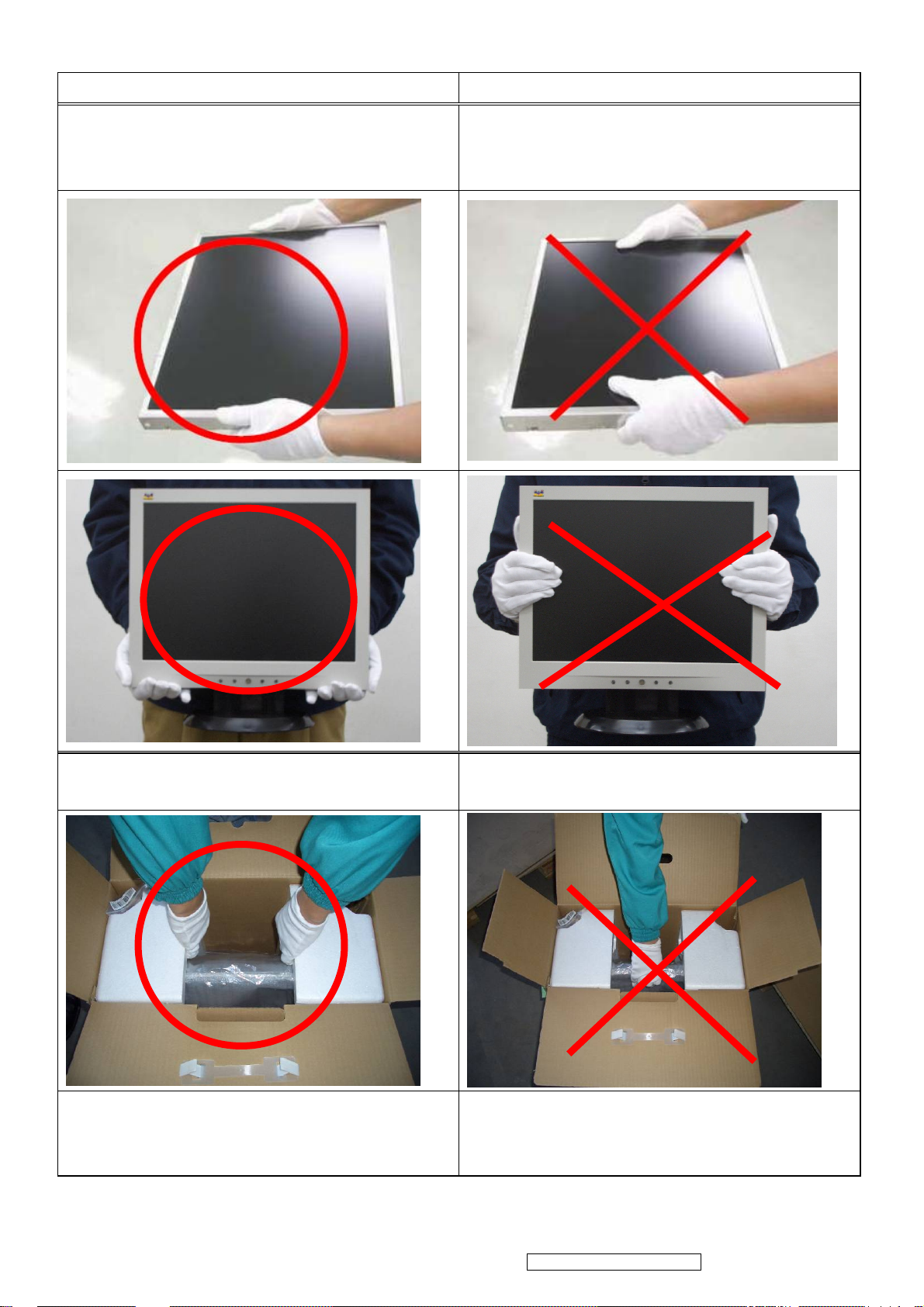
1.4 HANDING AND PLACING METHODS
Correct Methods: Incorrect Methods:
Only touch the metal frame of the LCD panel
or the front cover of the monitor. Do not touch
the surface of the polarizer.
Surface of the LCD panel is pressed by fingers
and that may cause “Mura.”
Take out the monitor with cushions
Place the monitor on a clean and soft foam
pad.
Taking out the monitor by grasping the LCD
panel. That may cause “Mura.”
Placing the monitor on foreign objects. That
could scratch the surface of the panel or cause
“Mura.”
2
ViewSonic Corporation Confidential - Do Not Copy VA502mb-1

Place the monitor on the lap, the panel surface
The panel is placed facedown on the lap. That
must be upwards.
may cause “Mura.”
3
ViewSonic Corporation Confidential - Do Not Copy VA502mb-1
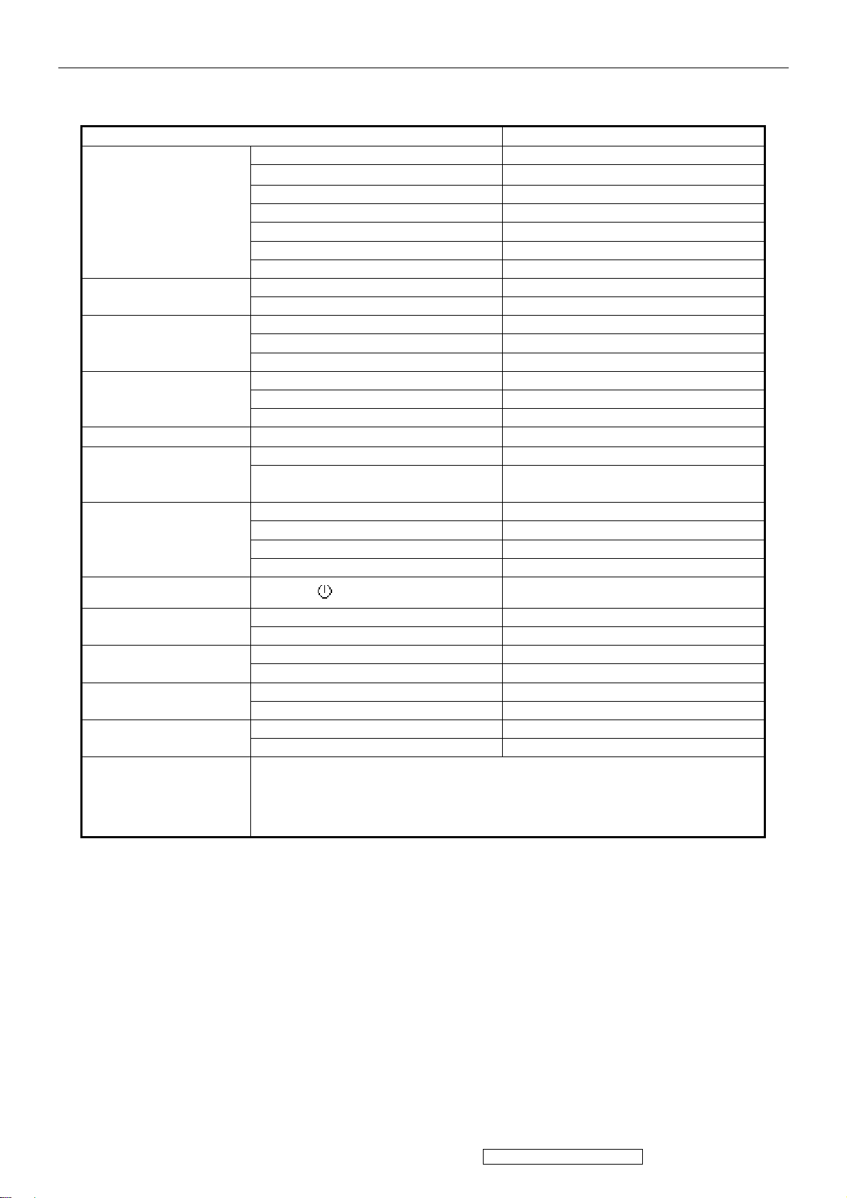
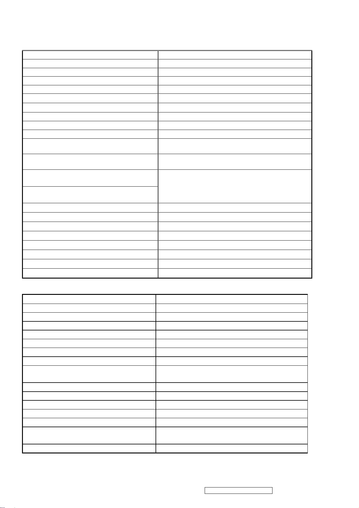
2. Specification
2.1 PRODUCT SPECIFICATIONS
INTRODUCTION
1st TFT LCD panel
Input Signal
Sync Compatibility
Compatibility
Power Voltage AC 100-240V, 50/60Hz Yes
Power Consumption
Ergonomics
FEATURES VA502mb
Size 15 “
Luminance (Typ)
Contrast Ratio (Typ) 450 :1
Colors 16.2 M colors (6+2bit panel)
Response Time (Typ) 16 ms
Viewing Angle (H/V) (Typ) 120° / 100 °
Recommend resolution 1024x768 @60Hz
Analog (75ohms, 0.7/1.0 Vp-p) Yes
Digital (DVI-D) No
Separate Sync Yes
Composite Sync No
Sync on Green No
PC Yes
Power Mac Yes
TV Box (NextVision 6) no
On Mode(Max / Typ) Under30 W in max
Active Off Mode (Max)
Tilt ( -5 ° - 22.5 °)
Swivel No
Pivot No
Height Adjust No
250 cd/㎡
Saving mode< 4W
Off mode <2 W
Yes
OSD Control [ 1 ] [ 2 ] [ ][▲] [▼] Yes
Dimension
Weight
Operating Condition
Storage Condition
Regulation UL, cUL, TUV/GS, TUV/ERGO (cover ISO13406-2),
Physical (W x H x D) 344.6x336.5 x 160 mm
Package (W x H x D) 408x414 x 314 mm
Physical (Net Weight) 3.0Kg
Package (Gross Weight) 4.2 Kg
Temperature ( / )℉℃ 41℉~95℉ / 5℃~35℃
Humidity (%) 10 % - 85 %
Temperature ( / )℉℃ -4℉~140℉ / -20℃~60℃
Humidity (%) 5 % - 85 %
4
ViewSonic Corporation Confidential - Do Not Copy VA502mb-1
PRODUCT DEFINITION AND SPECIFICATION
Product Name VA502mb
Model Number VS11352
Region M model for America
OSD Languages English, Spanish, Portuguese
TFT LCD Panel and Model # SAV Model # :150XG04TB
Scalar Novatech Model# NT68521A-XFG
Input Signal Analog
Sync Compatibility Separate
Adapter
No
Power Cable Refer to Appendix D
Analog Cable (1.8m, color : black), with PC
2001 and Hot Plug Detect &DDC
Audio Cable (1.8m, Color: black) with PC
2001
Yes
Yes
ViewSonic CD Wizard
English, Spanish, Portuguese,
ViewSonic Quick Start Guide
Screen Protector Mylar
Hi Pot label
QA pass label
Hg Warnning label
Yes
Yes
Yes
Yes
Warranty Sticker NO
Warranty Card NO
Carton Sticker NO
PE bag of Carton
NO
TFT LCD PANEL
st
Panel Source
1
SVA 150XG04TB
Type TN, LVDS
Active Size 304.128 mm (H) x 228.096mm (V)
Pixel Arrangement RGB Vertical Stripe
Pixel Pitch 0.297 mm
Glass Treatment Anti Glare (Hard coating 3H)
# of Backlights 2 CCFL edge-light
Backlight Life 30,000 Hours (Min)
Luminance –Condition: CT = 6500 K
Contrast = Max, Brightness = Max
250cd/m2 (Typ after 30 minute warm up)
Brightness Uniformity 1.3 (max)
Contrast Ratio 450:1 (Typ), 350:1 (Min)
Color Depth Vertical) 16.2 million colors (6+2 bit panel)
Viewing Angle (Horizontal) 120 deg (Typ)@ CR>10
Viewing Angle (Vertical) 100 deg (Typ) @ CR>10
Response Time
10%-90% @ Ta=25°C
16 ms (Tr= 12ms, Tf = 4 ms) (Typ)
25 ms (Tr= 18ms, Tf = 7 ms) (Max)
Panel Defects Please see Panel Quality Specifications.
5
ViewSonic Corporation Confidential - Do Not Copy VA502mb-1
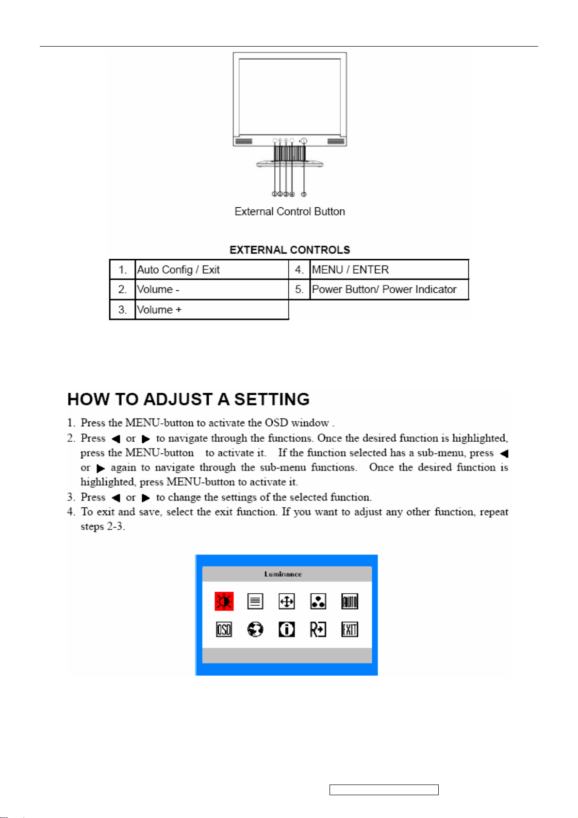
3. Front Panel Function Control Description
Do the following to adjust the display setting:
6
ViewSonic Corporation Confidential - Do Not Copy VA502mb-1
7
ViewSonic Corporation Confidential - Do Not Copy VA502mb-1
4. Circuit Description
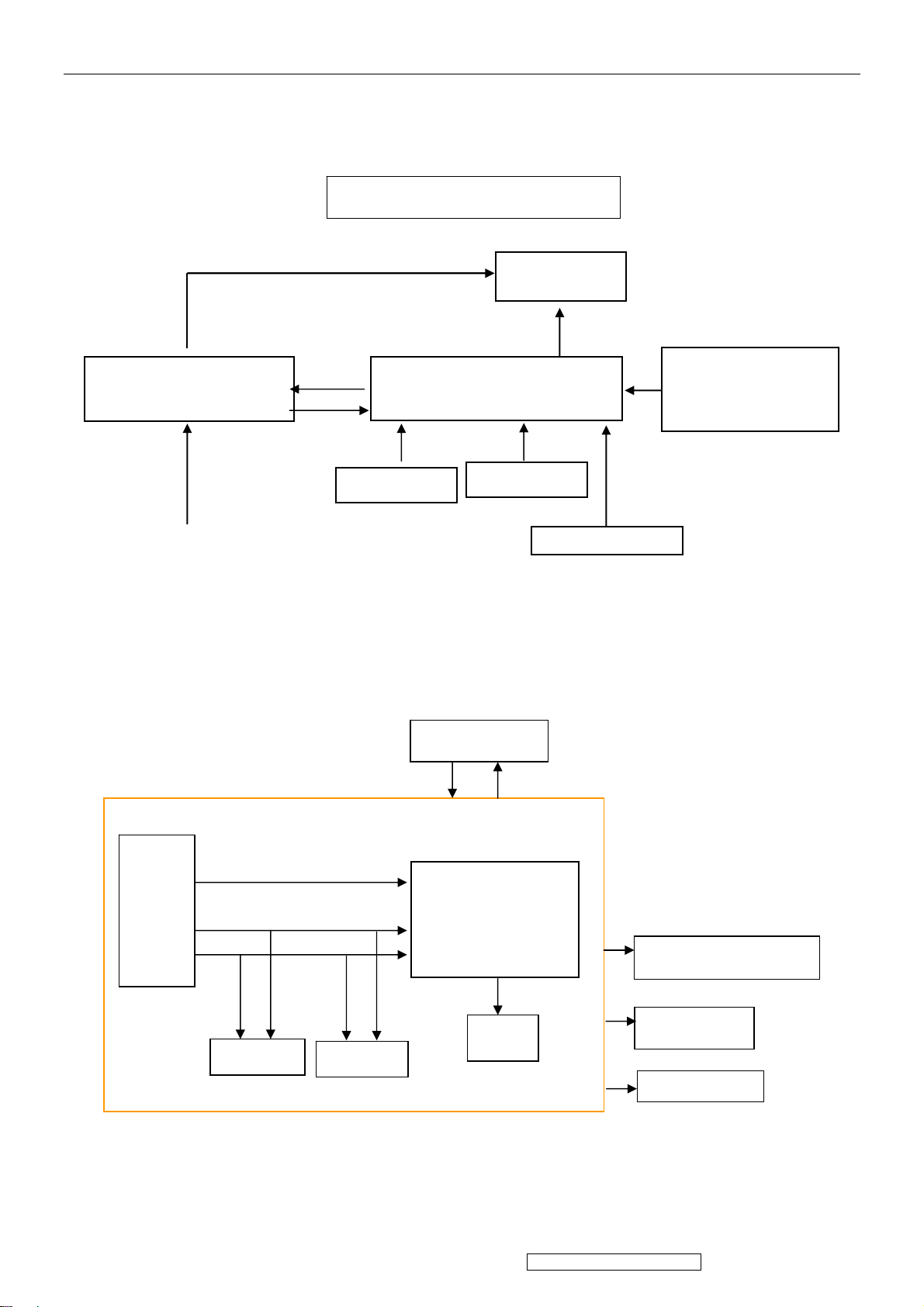
4.1 LCD MONITOR DESCRIPTION
The LCD MONITOR will contain a Main Board, a Power Board, Key Board and Audio board
which house the flat panel control logic, brightness control logic and DDC.
Monitor Block Diagram
Power Board
(Include: adapter, inverter)
AC-IN
100V-240V
CCFL Drive.
Main Board
Key Board
Flat Panel and
CCFL backlight
Audio Board
HOST Computer
RS232 Connector
For white balance
adjustment in factory
mode
Video signal, DDC
4.2 MAIN BOARD BLOCK FUNCTION DESCRIPTION
The main board contains panel control logic, brightness control logic; DDC and DC convert DC
circuit and so on.
R
G
B
H
V
SDA
SCL
EPROM
EPROM
Power board
MST8011B
OSC
Backlight and Panel
Audio board
Key board
8
ViewSonic Corporation Confidential - Do Not Copy VA502mb-1
4.3 PWPC BOARD BLOCK FUNCTION DESCRIPTION
Q203
PWPC board combines to adapter and inverter, Adapter which commonly consists of bridge
rectifier and filter, start circuit, PWM control circuit, protection circuits and convert to 12V, 5V DC
voltage by input 90V-240V AC voltage that provide power supply for each chips in the main board
and inverter. Inverter is DC TO AC circuit. It changes the 12v DC of power supply to about
600-800v AC that drives the backlight. It mostly consists of starting circuit, PWM controller, DC
changing circuit, LC surging circuit, output circuit and protection circuit etc.
AC input
EMI filter
Bridge
Rectifier
and Filter
Transformer
Rectifier
CMOS
Lamp
Start Circuit
R906, R907
Control
OSC and
Output
Circuit
Feedback
Circuit
PWM
Over
Voltage
DC Convert
Circuit
MOSFET
PWM
Control
Over
Voltage
Protect
CN102
5V
12V
ON/OFF
ON/OFF
Control
DIM
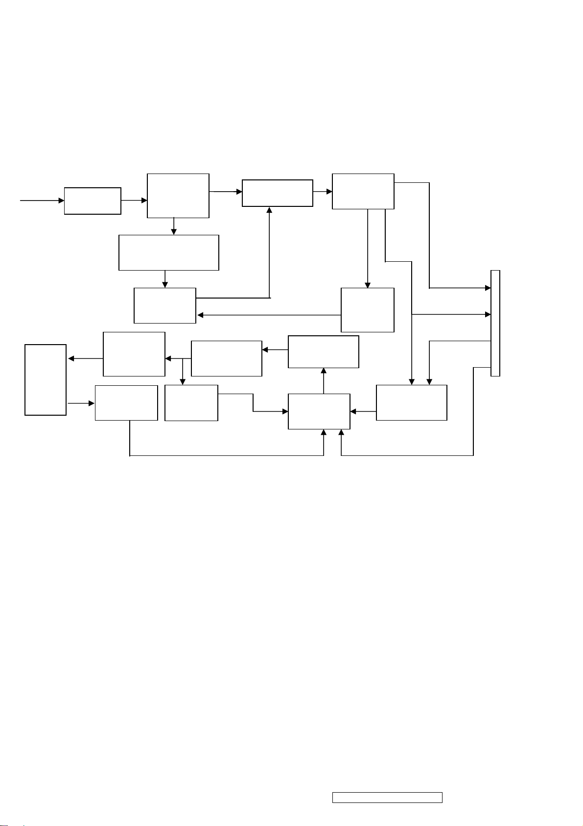
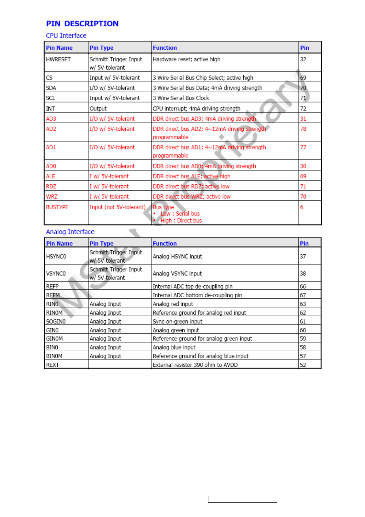
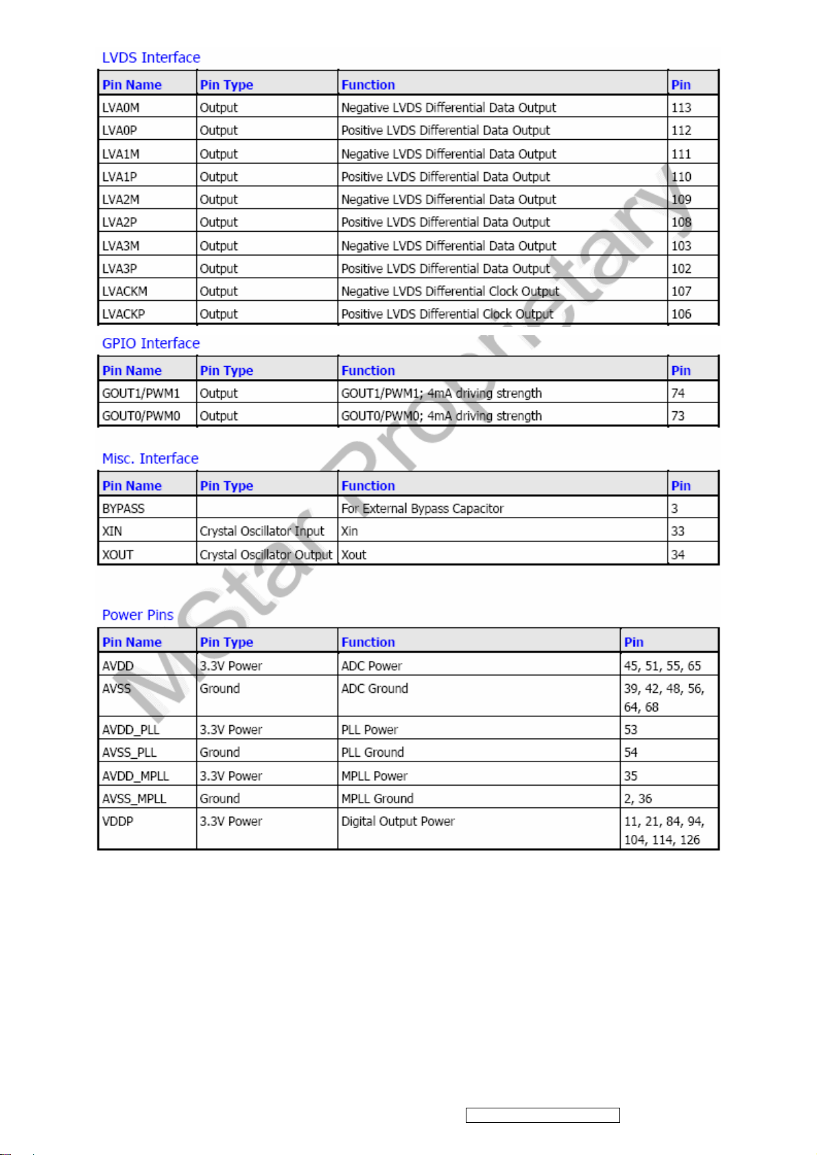
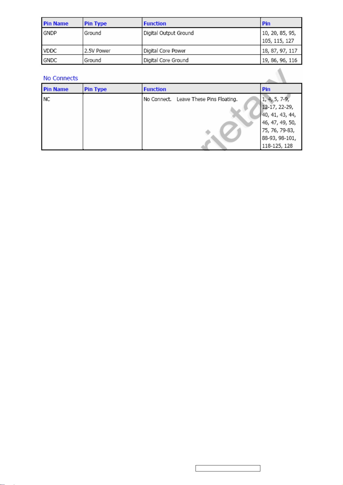
4.4 INTRODUCTION OF IC
MST8011B (U401): integrate ADC, OSD, SCALER, LVDS, convert analog RGB into digital and
room and shrink scaling output to LCD panel.
PIN Function:
9
ViewSonic Corporation Confidential - Do Not Copy VA502mb-1
10
ViewSonic Corporation Confidential - Do Not Copy VA502mb-1
11
ViewSonic Corporation Confidential - Do Not Copy VA502mb-1
AIC1084-33PM (U202): DC power convert, used to 5v convert 3.3v.
RT9164-25PL (U201): DC power convert, used to 5v convert 2.5v.
W78E065A40PL (U601):
The W78E65 is an 8-bit microcontroller which has an in-system programmable Flash EPROM for
firmware updating. The instruction set of the W78E65 is fully compatible with the standard 8052.
The W78E65 contains a 64K bytes of main ROM and a 4K bytes of auxiliary ROM which allows
the contents of the 64KB main ROM to be updated by the loader program located at the 4KB
auxiliary ROM; 256+1K bytes of on-chip RAM; four 8-bit bi-directional and bit-addressable I/O
ports; an additional 4-bit port P4; three 16-bit timer/counters; a serial port. These peripherals are
supported by a eight sources two-level interrupt capability. To facilitate programming and
verification, the ROM inside the W78E65 allows the program memory to be programmed and
read electronically. Once the code is confirmed, the user can protect the code for security.
The W78E65 microcontroller has two power reduction modes, idle mode and power-down mode,
both of which are software selectable. The idle mode turns off the processor clock but allows for
continued peripheral operation. The power-down mode stops the crystal oscillator for minimum
power consumption. The external clock can be stopped at any time and in any state without
affecting the processor.
12
ViewSonic Corporation Confidential - Do Not Copy VA502mb-1
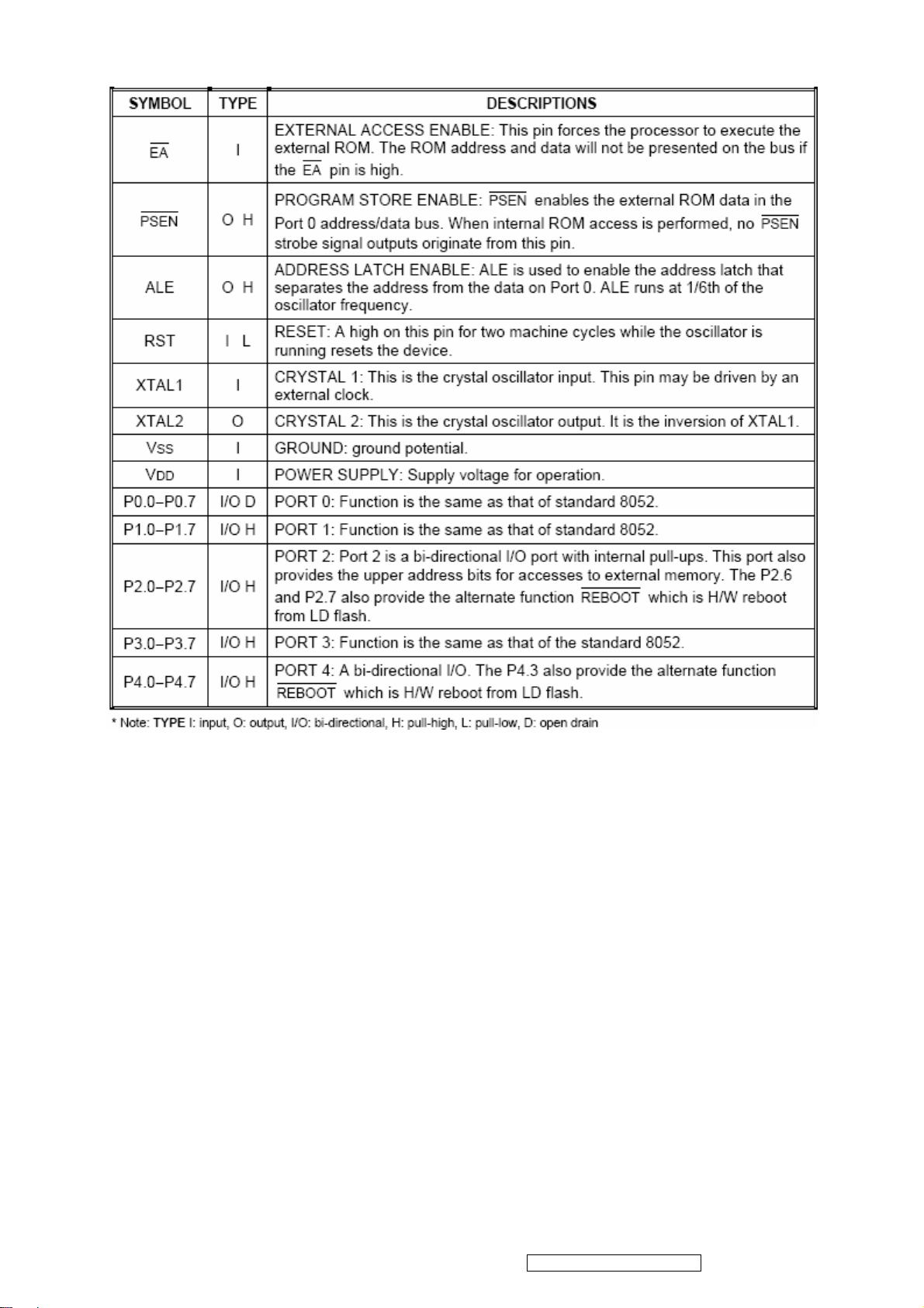
PIN Descriptions:
13
ViewSonic Corporation Confidential - Do Not Copy VA502mb-1
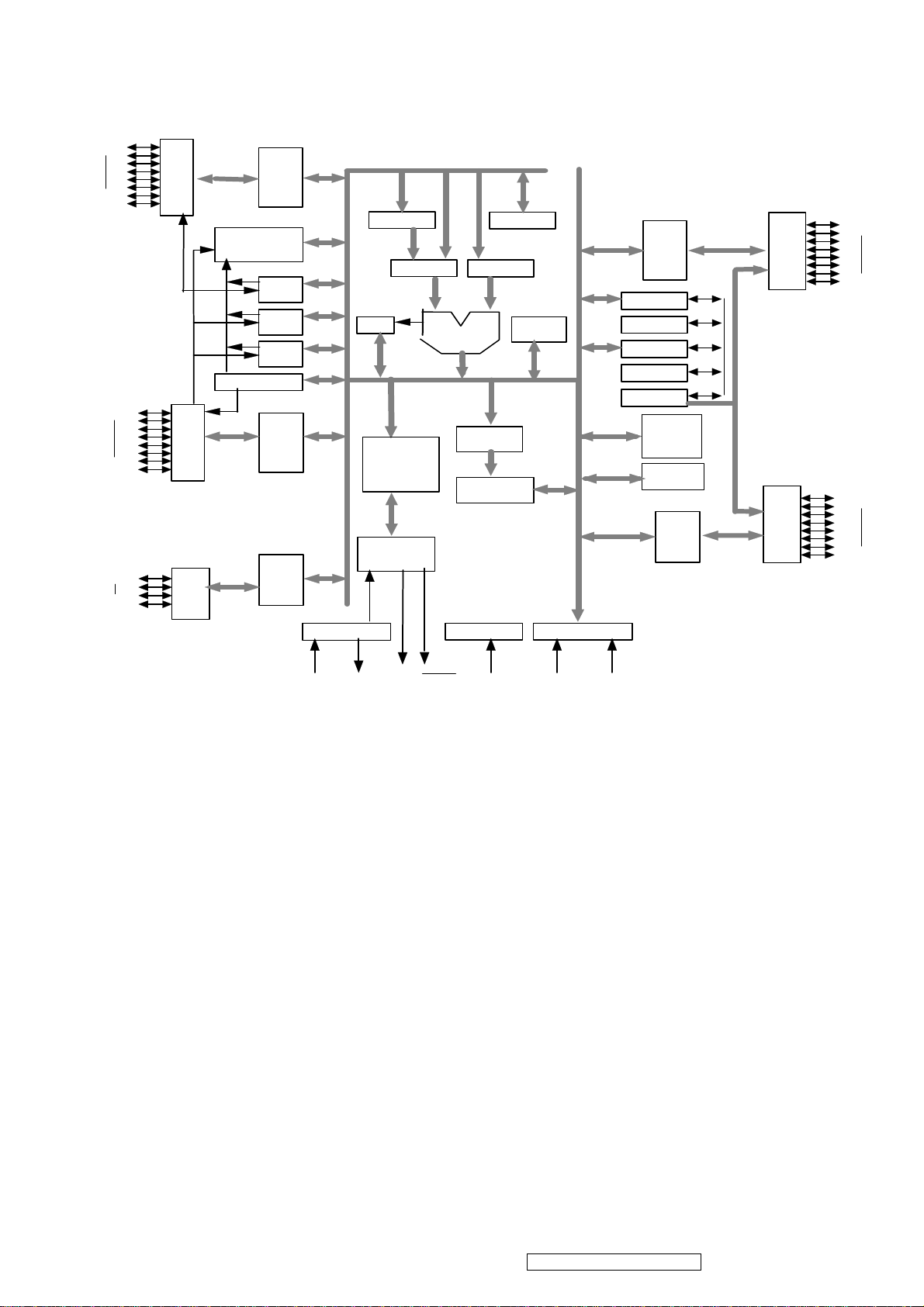
Circuit Diagram
P1.0
Port
1
P1.7
P3.0
Port
3
P3.7
P4.0
P4.7
Port
4
Interrupt
UART
Port 1
Latch
Timer
2
Timer
0
Timer
1
Port 3
Latch
Port 4
Latch
Oscillator
ACC
PSW
Instruction
Decoder
&
Sequencer
Bus & Clock
Controller
T1
ALU
SFR RAM
Address
256+1K bytes
RAM & SFR
Reset Block
B
Port 0
T2
Latch
Port
0
P0.0
P0.7
DPTR
Stack
Pointer
Temp Reg.
PC
Incrementor
Addr. Reg.
64KB
Flash E ROM
4KB
Flash EROM
P2.0
Port 2
Latch
Port
2
P2.7
Power control
XTAL1
ALE
PSEN
RSTXTAL2
VCC
Vss
TDA7496(U201): The TDA7496L is a stereo 2W+2W class AB power amplifier assembled in the
@ Powerdip 14+3+3 package, specially designed for high quality sound, TV and Monitor
applications. Features of the TDA7496L include linear volume control, Stand-by and mute
functions. The function of each pin and the inside circuit diagram are as follows:
14
ViewSonic Corporation Confidential - Do Not Copy VA502mb-1
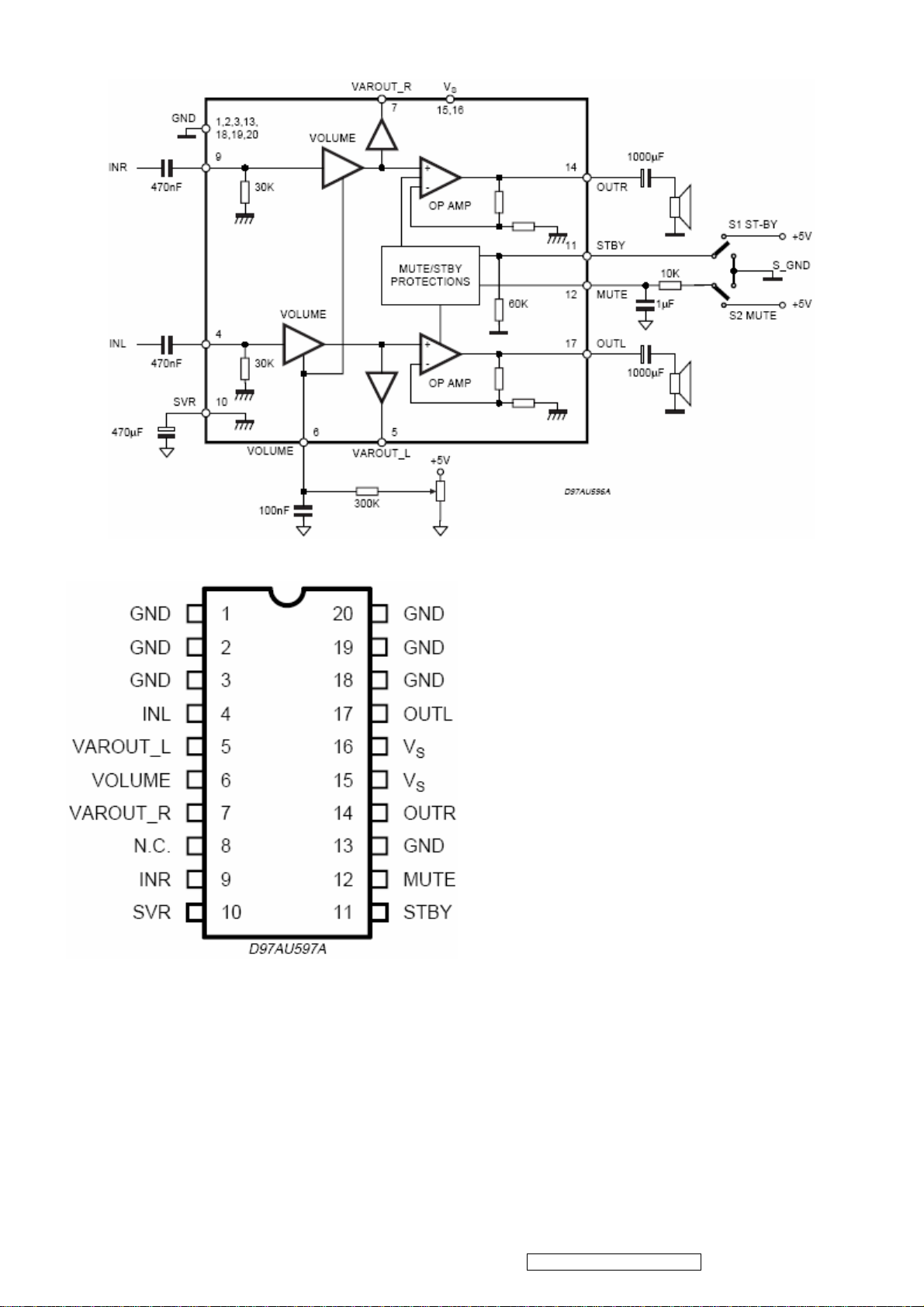
Block Diagram
PIN Function
15
ViewSonic Corporation Confidential - Do Not Copy VA502mb-1

LD7552BPN (IC901): The LD7552B are low cost, low startup current, current
mode PWM controllers with green-mode power- saving operation. The integrated functions
include the leading-edge blanking of the current sensing, internal slope
compensation. They provide the users a superior AC/DC power application of higher efficiency,
low external component counts, and lower cost solution. Furthermore, LD7552B feature more
protections like OLP (Over Load Protection) and OVP (Over Voltage Protection) to eliminate the
external protection circuits. It is designed for the switching adaptor with 30W~60W output,
offered in both SOP-8 and DIP-8 package.
The function of each pin and the inside circuit diagram are as follows:
PIN Descriptions:
16
ViewSonic Corporation Confidential - Do Not Copy VA502mb-1
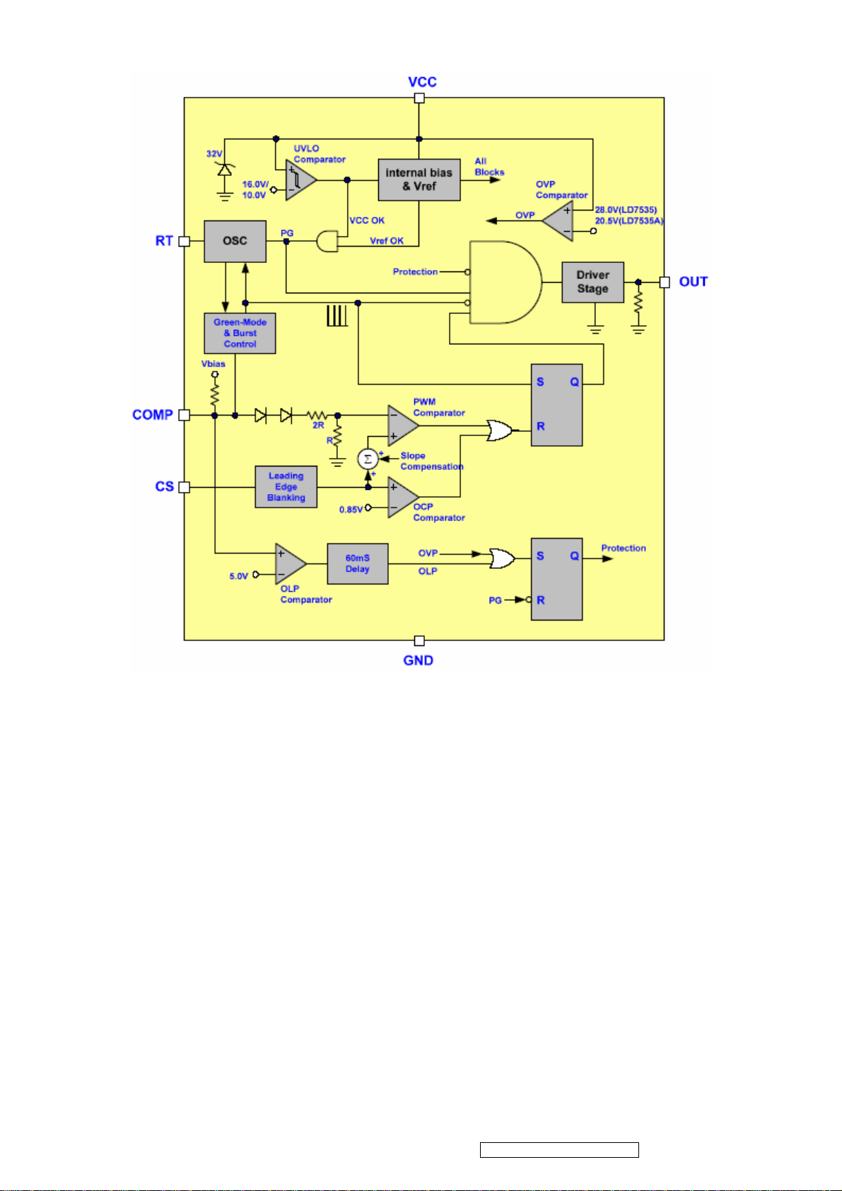
Block Diagram
BA9741F (U201): The BA9741F is a timer latch, short-circuit protection circuit is built in. Circuit
to prevent malfunction during low input voltage is built in. Built-in reference voltage(2.5v)circuit
with output pin. Dead time over the whole range of possible to adjust half period of whole duty
range. Recommendable for regulator in camcorder.
The function of each pin and the circuit diagram inside are as follows:
17
ViewSonic Corporation Confidential - Do Not Copy VA502mb-1
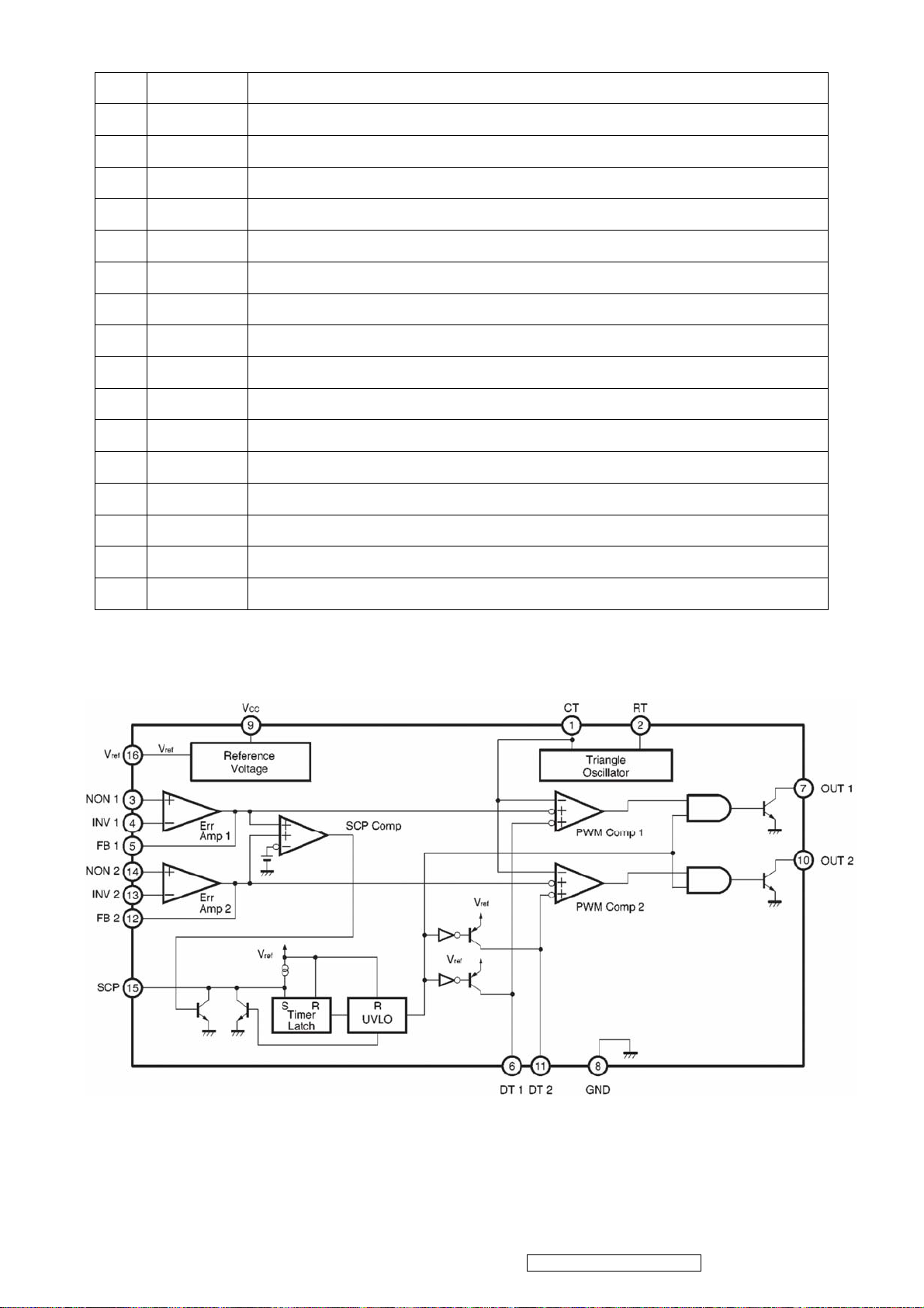
PIN Descriptions:
Pin Names Function
1 CT External timing capacitance
2 RT External timing resistance
3 NON1 Positive input for error amplifier 1
4 INV1 Negative input for error amplifier 1
5 FB1 Output for error amplifier 1
6 DT1 Output 1 dead time/soft start setting
7 OUT1 Output 1
8 GND Ground
9 Vcc Power Supply
10 OUT2 Output 2
11 DT2 Output 2 dead time/soft start setting
12 FB2 Output for error amplifier 2
13 INV2 Negative input for error amplifier 2
14 NON2 Positive input for error amplifier 2
15 SCP Timing latch setting
16 VREF Reference voltage(2.5v) output
Block Diagram
18
ViewSonic Corporation Confidential - Do Not Copy VA502mb-1

5. Adjustment Procedure
5.1 ADJUSTMENT CONDITIONS AND PRECAUTIONS
1. Approximately 30 minutes should be allowed for warm up before proceeding.
2. Adjustments should be undertaken only on those necessary elements since most of them
have been carefully preset at the factory.
3. ESD protection is needed before adjustment.
5.2 MAIN ADJUSTMENTS
NO. FUNCTIONS DESIGNATION
1. White Balance Function Key
2. Geometry Function Key
5.3 ALIGNMENT PROCEDURES
Approximately 30 minutes should be allowed for warm up before proceeding
White-Balance adjustment.
1. Adjust of White Balance
1.)How to do the Chroma-7120 MEM .Channel setting
A. Reference to chroma 7120 user guide
B. Use “ SC” key and “ NEXT” key to modify xyY value and use “ID” key to modify the TEXT
description Following is the procedure to do white-balance adjust
2.)Setting the color temp. You want
A. MEM.CHANNEL9 ( 9300 color):
9300 color temp. parameter is Wx = 0.283 ±0.03;Wy = 0.298 ±0.03;
Y = 200 ±20 cd/m
B. MEM.CHANNEL10 ( 6500 color):
2 ,
6500 color temp. parameter is Wx = 0.313±0.03;Wy = 0.329 ±0.03;
Y = 200 ±20 cd/m
C. MEM.CHANNEL10 ( SRGB color):
2,
6500 color temp. parameter is Wx = 0.313±0.03;Wy = 0.329 ±0.03;
Y = 200 ±20 cd/m
2,
19
ViewSonic Corporation Confidential - Do Not Copy VA502mb-1
 Loading...