

Page 1

ViewSonic VA502mb-1
Model No. VS11352
15” Color TFT LCD Display
(VA502mb-1_SM Rev. 1a Dec. 2006)
Service Manual
ViewSonic 381 Brea Canyon Road, Walnut, California 91789 USA - (800) 888-8583
Page 2

Copyright
Copyright © 2006 by ViewSonic Corporation. All rights reserved. No part of this publication
may be reproduced, transmitted, transcribed, stored in a retrieval system, or translated into any
language or computer language, in any form or by any means, electronic, mechanical, magnetic,
optical, chemical, manual or otherwise, without the prior written permission of ViewSonic
Corporation.
Disclaimer
ViewSonic makes no representations or warranties, either expressed or implied, with respect to
the contents hereof and specifically disclaims any warranty of merchantability or fitness for any
particular purpose. Further, ViewSonic reserves the right to revise this publication and to make
changes from time to time in the contents hereof without obligation of ViewSonic to notify any
person of such revision or changes.
Trademarks
Optiquest is a registered trademark of ViewSonic Corporation.
ViewSonic is a registered trademark of ViewSonic Corporation.
All other trademarks used within this document are the property of their respective owners.
Revision History
Revision SM Editing Date ECR Number Description of Changes Editor
1a 12/20/2006 Initial Release Jamie Chang
i
ViewSonic Corporation Confidential - Do Not Copy VA502mb-1
Page 3

TABLE OF CONTENTS
1. Precautions and Safety Notices 1
2. Specification 4
3. Front Panel Function Control Description 6
4. Circuit Description 8
5. Adjustment Procedure 19
6. Troubleshooting Flow Chart 39
7. Block Diagram 40
8. Schematic Diagrams 41
9. PCB Layout Diagrams 50
10. Exploded Diagram and Exploded Parts List 56
11. Recommended Spare Parts List 60
ii
ViewSonic Corporation Confidential - Do Not Copy VA502mb-1
Page 4

1. Precautions and Safety Notices
1.1 SAFETY PRECAUTIONS
This monitor is manufactured and tested on a ground principle that a user’s safety comes
first. However, improper use or installation may cause damage to the monitor as well as the
user. Carefully go over the following WARNINGS before installing and keep this guide
handy.
WARNINGS
- This monitor should be operated only at the correct power sources indicated on the label on
the rear end of the monitor. If you’re unsure of the power supply in your residence, consult
you local dealer or power company.
- Use only the special power adapter that comes with this monitor for power input.
- Do not try to repair the monitor your self as it contains no userserviceable parts. This
monitor should only be repaired by a qualified technician.
- Do not remove the monitor cabinet. There is highvoltage parts inside that may cause
electric shock to human bodies, even when the power cord is unplugged.
- Stop using the monitor if the cabinet is damaged. Have it checked by a service technician.
- Put your monitor only in a clean, dry environment. If it gets wet, unplug the power cable
immediately and consult your service technician.
- Always unplug the monitor before cleaning it .Clean the cabinet with a clean, dry cloth.
Apply nonammonia based cleaner onto the cloth, not directly onto the glass screen.
- Keep the monitor away from magnetic objects, motors, TV sets, and transformer.
- Do not place heavy objects on the monitor or power cord.
1.2 PRODUCT SAFETY NOTICE
Many electrical and mechanical parts in this chassis have special safety visual inspections
and the protection afforded by them cannot necessarily be obtained by using replacement
components rated for higher voltages, wattage, etc. Before replacing any of these
components read the parts list in this manual carefully. The use of substitute replacement
parts which do not have the same safety characteristics as specified in the parts list may
create shock, fire ,or other hazards.
1.3 SERVICE NOTES
When replacing parts or circuit boards, clamp the lead wires around terminals before
soldering.
When replacing a high wattage resistor(more than 1W of metal oxide film resistor) in circuit
board, keep the resistor about 5mm away from circuit board.
Keep wires away from high voltage, high temperature components and sharp edges.
Keep wires in their original position so as to reduce interference.
Usage of this product please refer to also user’s manual.
1
ViewSonic Corporation Confidential - Do Not Copy VA502mb-1
Page 5
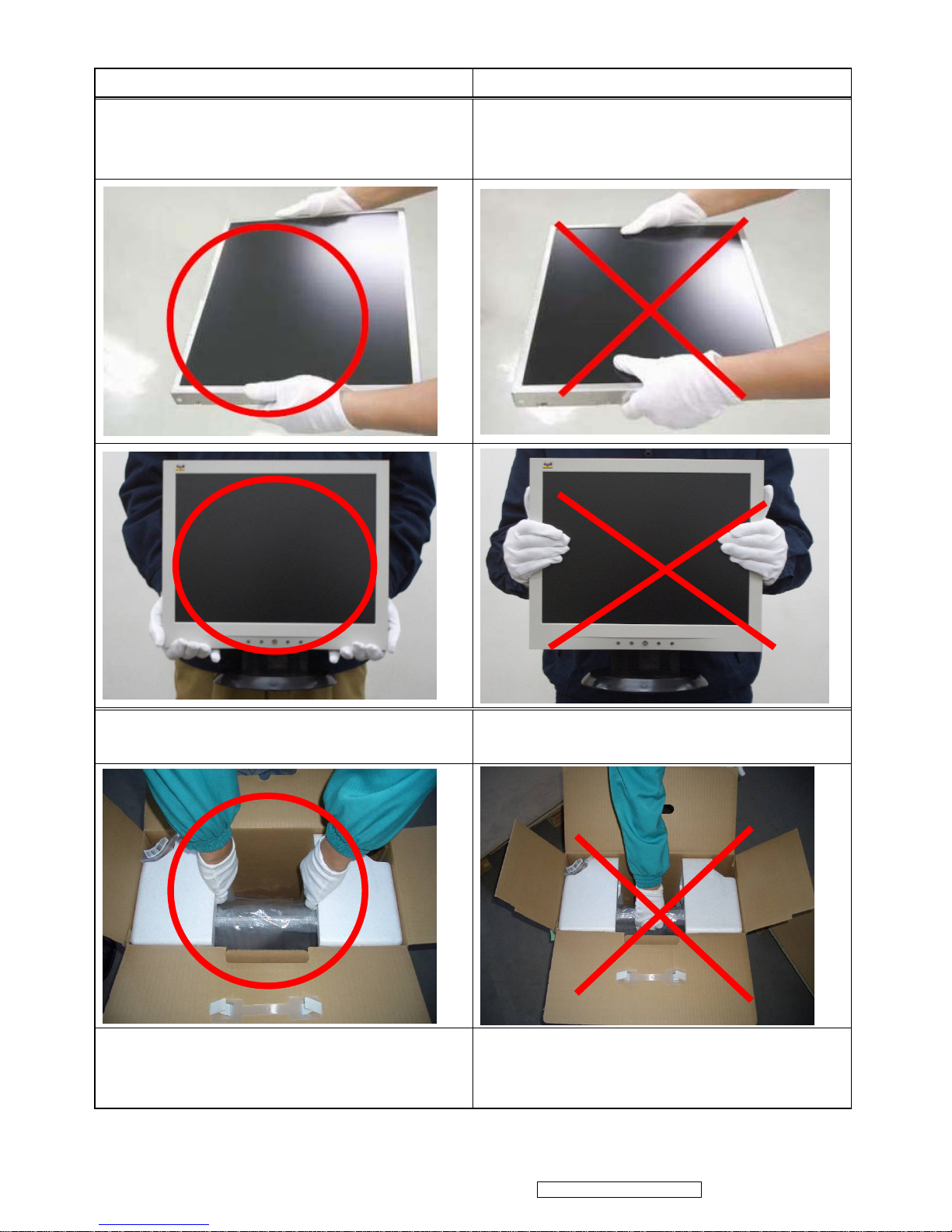
1.4 HANDING AND PLACING METHODS
Correct Methods: Incorrect Methods:
Only touch the metal frame of the LCD panel
or the front cover of the monitor. Do not touch
the surface of the polarizer.
Surface of the LCD panel is pressed by fingers
and that may cause “Mura.”
Take out the monitor with cushions
Taking out the monitor by grasping the LCD
panel. That may cause “Mura.”
Place the monitor on a clean and soft foam
pad.
Placing the monitor on foreign objects. That
could scratch the surface of the panel or cause
“Mura.”
2
ViewSonic Corporation Confidential - Do Not Copy VA502mb-1
Page 6
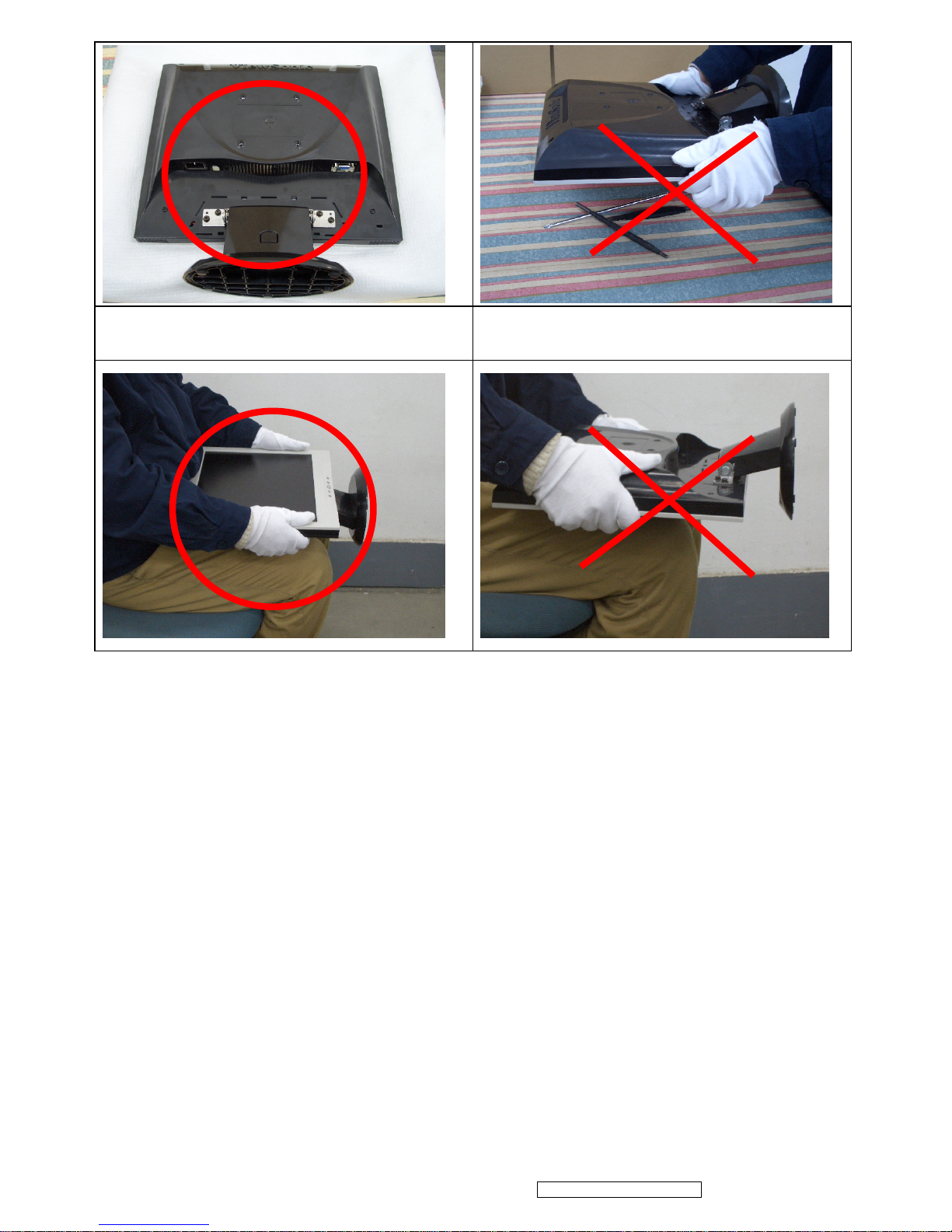
Place the monitor on the lap, the panel surface
must be upwards.
The panel is placed facedown on the lap. That
may cause “Mura.”
3
ViewSonic Corporation Confidential - Do Not Copy VA502mb-1
Page 7
2. Specification
2.1 PRODUCT SPECIFICATIONS
4
ViewSonic Corporation Confidential - Do Not Copy VA502mb-1
INTRODUCTION
FEATURES VA502mb
Size 15 “
Luminance (Typ)
250 cd/㎡
Contrast Ratio (Typ) 450 :1
Colors 16.2 M colors (6+2bit panel)
Response Time (Typ) 16 ms
Viewing Angle (H/V) (Typ) 120° / 100 °
1st TFT LCD panel
Recommend resolution 1024x768 @60Hz
Analog (75ohms, 0.7/1.0 Vp-p) Yes
Input Signal
Digital (DVI-D) No
Separate Sync Yes
Composite Sync No
Sync Compatibility
Sync on Green No
PC Yes
Power Mac Yes
Compatibility
TV Box (NextVision 6) no
Power Voltage AC 100-240V, 50/60Hz Yes
On Mode(Max / Typ) Under30 W in max
Power Consumption
Active Off Mode (Max)
Saving mode< 4W
Off mode <2 W
Tilt ( -5 ° - 22.5 °)
Yes
Swivel No
Pivot No
Ergonomics
Height Adjust No
OSD Control [ 1 ] [ 2 ] [ ][▲] [▼] Yes
Physical (W x H x D) 344.6x336.5 x 160 mm
Dimension
Package (W x H x D) 408x414 x 314 mm
Physical (Net Weight) 3.0Kg
Weight
Package (Gross Weight) 4.2 Kg
Temperature ( / )℉℃ 41℉~95℉ / 5℃~35℃
Operating Condition
Humidity (%) 10 % - 85 %
Temperature ( / )℉℃ -4℉~140℉ / -20℃~60℃
Storage Condition
Humidity (%) 5 % - 85 %
Regulation UL, cUL, TUV/GS, TUV/ERGO (cover ISO13406-2),
Page 8
5
ViewSonic Corporation Confidential - Do Not Copy VA502mb-1
PRODUCT DEFINITION AND SPECIFICATION
Product Name VA502mb
Model Number VS11352
Region M model for America
OSD Languages English, Spanish, Portuguese
TFT LCD Panel and Model # SAV Model # :150XG04TB
Scalar Novatech Model# NT68521A-XFG
Input Signal Analog
Sync Compatibility Separate
Adapter
No
Power Cable Refer to Appendix D
Analog Cable (1.8m, color : black), with PC
2001 and Hot Plug Detect &DDC
Yes
Audio Cable (1.8m, Color: black) with PC
2001
Yes
ViewSonic CD Wizard
ViewSonic Quick Start Guide
English, Spanish, Portuguese,
Screen Protector Mylar
Yes
Hi Pot label
Yes
QA pass label
Yes
Hg Warnning label
Yes
Warranty Sticker NO
Warranty Card NO
Carton Sticker NO
PE bag of Carton
NO
TFT LCD PANEL
1
st
Panel Source
SVA 150XG04TB
Type TN, LVDS
Active Size 304.128 mm (H) x 228.096mm (V)
Pixel Arrangement RGB Vertical Stripe
Pixel Pitch 0.297 mm
Glass Treatment Anti Glare (Hard coating 3H)
# of Backlights 2 CCFL edge-light
Backlight Life 30,000 Hours (Min)
Luminance –Condition: CT = 6500 K
Contrast = Max, Brightness = Max
250cd/m2 (Typ after 30 minute warm up)
Brightness Uniformity 1.3 (max)
Contrast Ratio 450:1 (Typ), 350:1 (Min)
Color Depth Vertical) 16.2 million colors (6+2 bit panel)
Viewing Angle (Horizontal) 120 deg (Typ)@ CR>10
Viewing Angle (Vertical) 100 deg (Typ) @ CR>10
Response Time
10%-90% @ Ta=25°C
16 ms (Tr= 12ms, Tf = 4 ms) (Typ)
25 ms (Tr= 18ms, Tf = 7 ms) (Max)
Panel Defects Please see Panel Quality Specifications.
Page 9
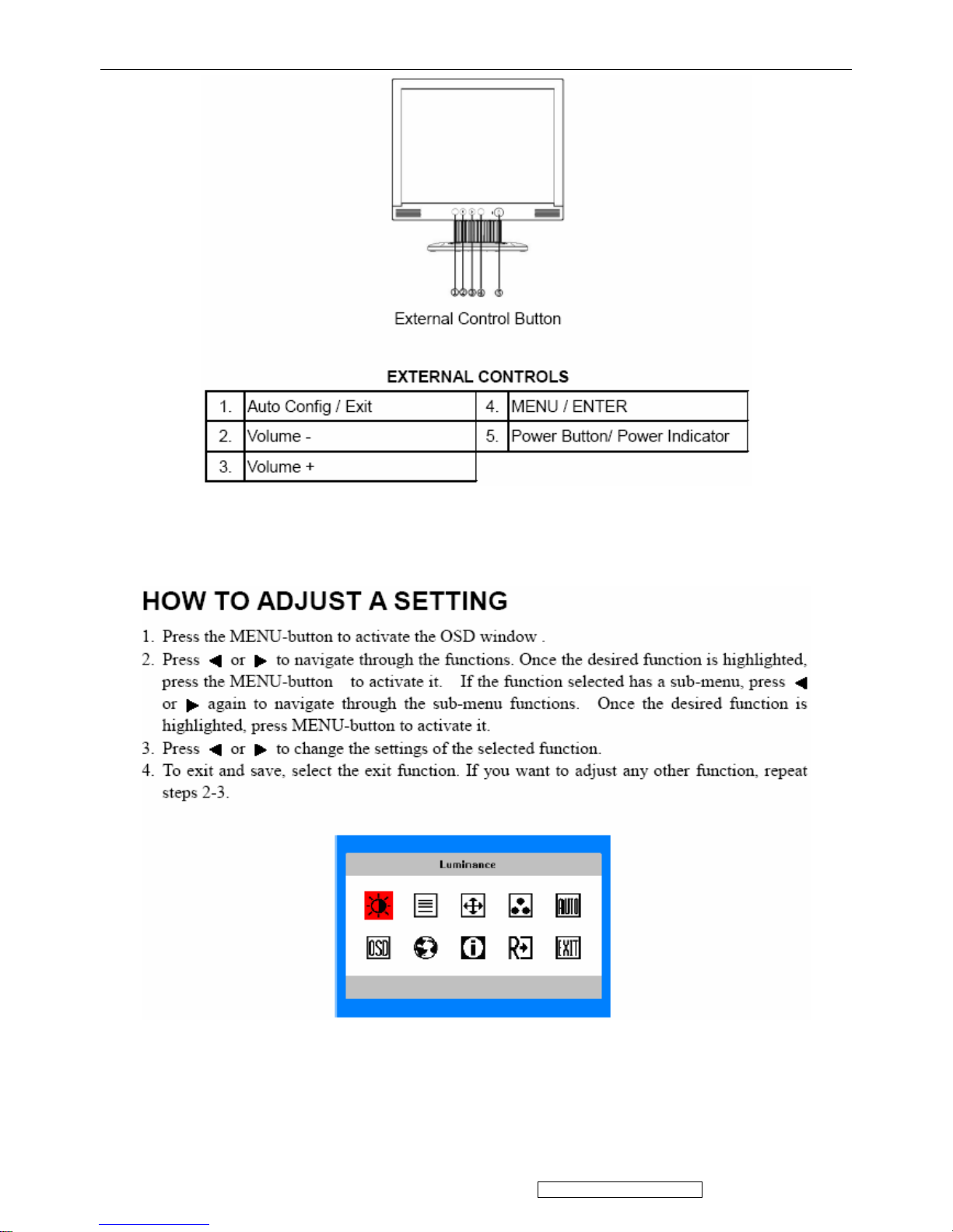
3. Front Panel Function Control Description
Do the following to adjust the display setting:
6
ViewSonic Corporation Confidential - Do Not Copy VA502mb-1
Page 10
7
ViewSonic Corporation Confidential - Do Not Copy VA502mb-1
Page 11
4. Circuit Description
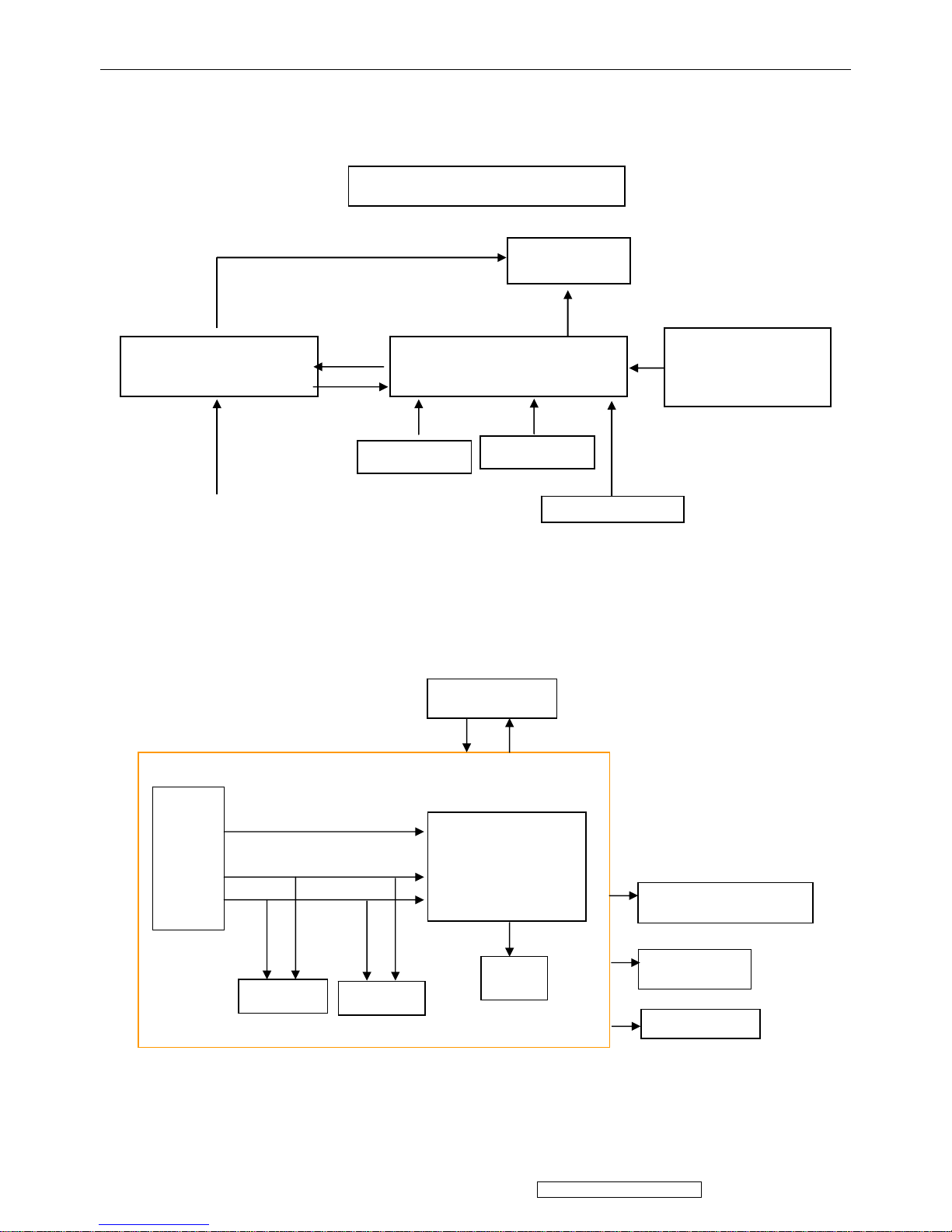
4.1 LCD MONITOR DESCRIPTION
The LCD MONITOR will contain a Main Board, a Power Board, Key Board and Audio board
which house the flat panel control logic, brightness control logic and DDC.
4.2 MAIN BOARD BLOCK FUNCTION DESCRIPTION
The main board contains panel control logic, brightness control logic; DDC and DC convert DC
circuit and so on.
Power Board
(Include: adapter, inverter)
Flat Panel and
CCFL backlight
Main Board
Key Board
RS232 Connector
For white balance
adjustment in factory
mode
HOST Computer
CCFL Drive.
Monitor Block Diagram
AC-IN
100V-240V
Video signal, DDC
Audio Board
Power board
R
G
B
H
V
SDA
SCL
OSC
Backlight and Panel
EPROM
EPROM
MST8011B
Audio board
Key board
8
ViewSonic Corporation Confidential - Do Not Copy VA502mb-1
Page 12
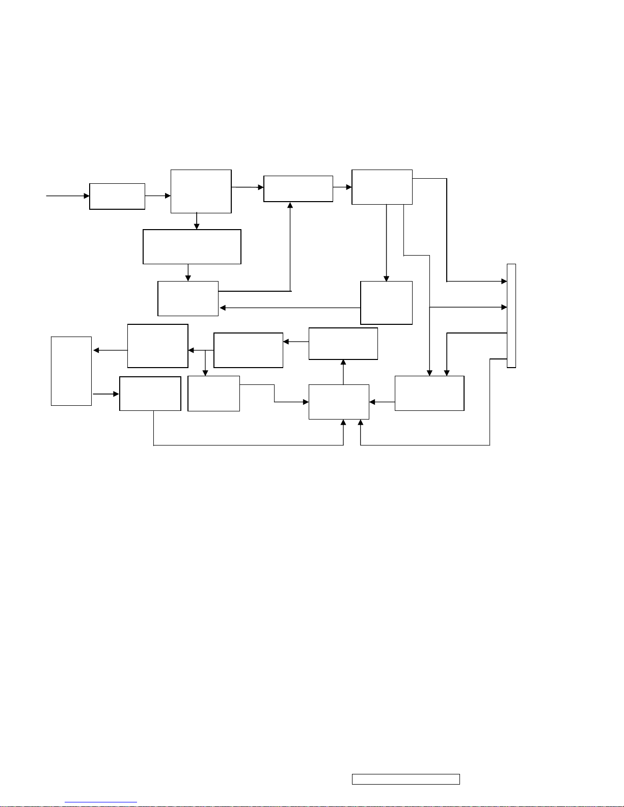
4.3 PWPC BOARD BLOCK FUNCTION DESCRIPTION
PWPC board combines to adapter and inverter, Adapter which commonly consists of bridge
rectifier and filter, start circuit, PWM control circuit, protection circuits and convert to 12V, 5V DC
voltage by input 90V-240V AC voltage that provide power supply for each chips in the main board
and inverter. Inverter is DC TO AC circuit. It changes the 12v DC of power supply to about
600-800v AC that drives the backlight. It mostly consists of starting circuit, PWM controller, DC
changing circuit, LC surging circuit, output circuit and protection circuit etc.
AC input
EMI filter
Bridge
Rectifier
and Filter
Start Circuit
R906, R907
PWM
Control
Over
Voltage
Protect
Rectifier
CMOS
ON/OFF
Control
PWM
Control
Feedback
Circuit
OSC and
Output
Circuit
DC Convert
Circuit
MOSFET
Q203
Over
Voltage
CN102
Transformer
Lamp
5V
12V
ON/OFF
DIM
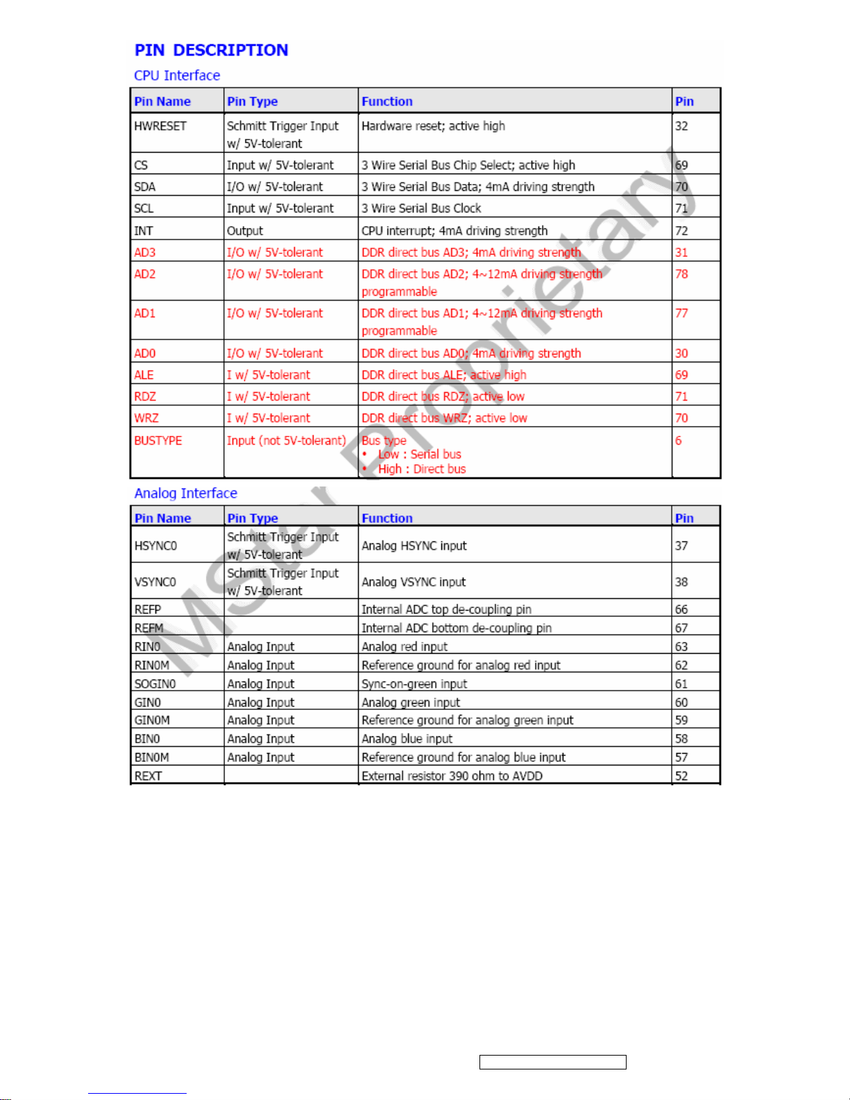
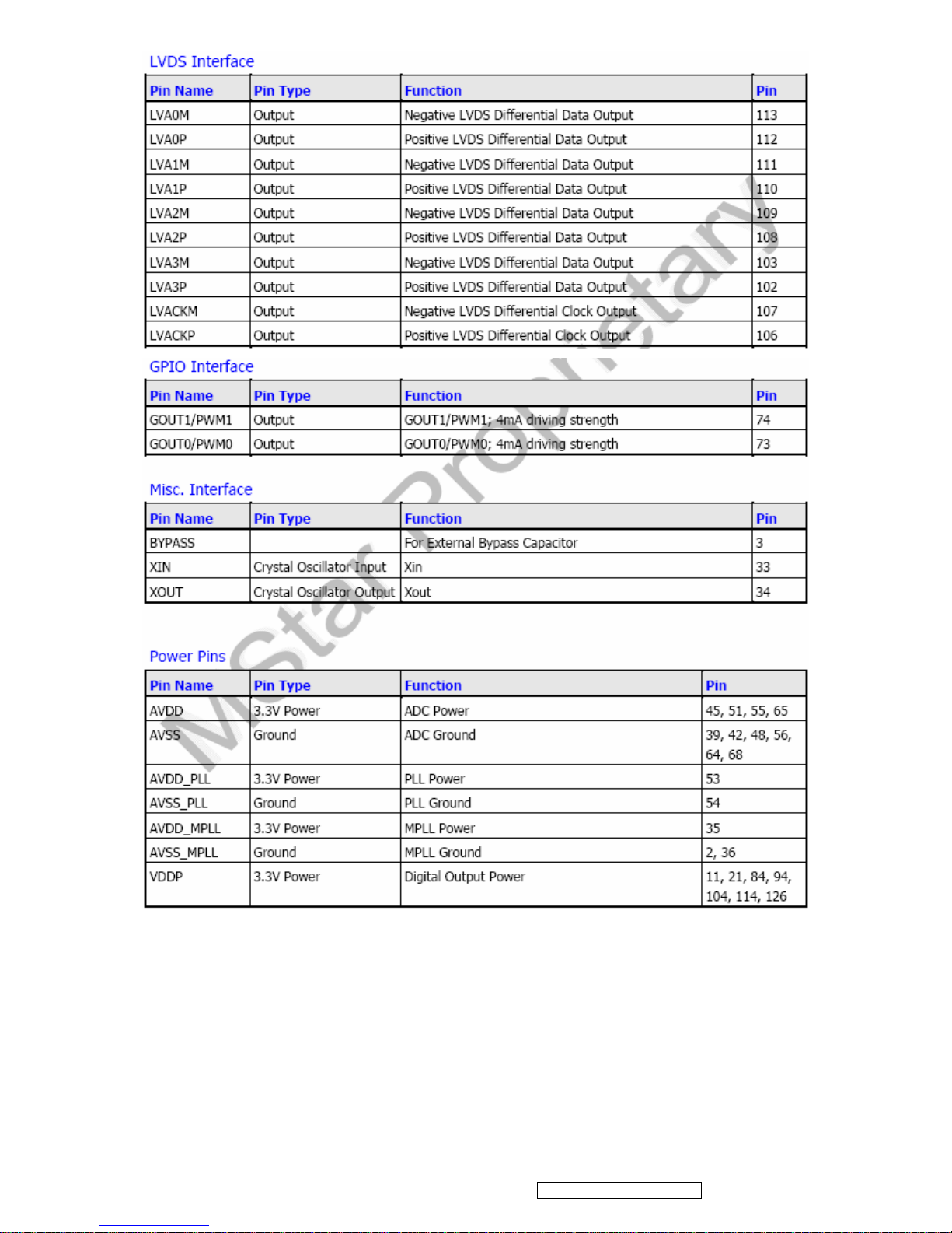
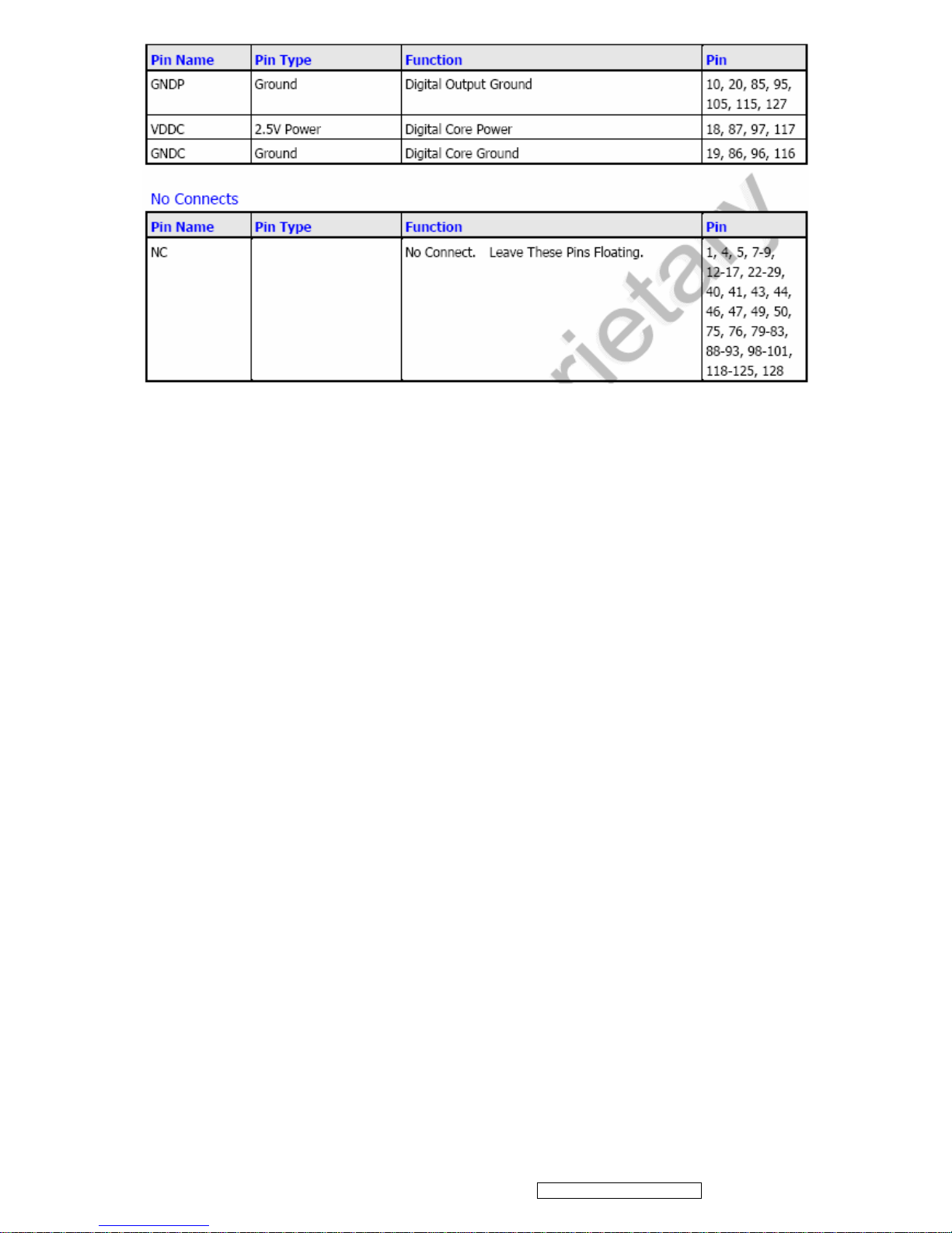
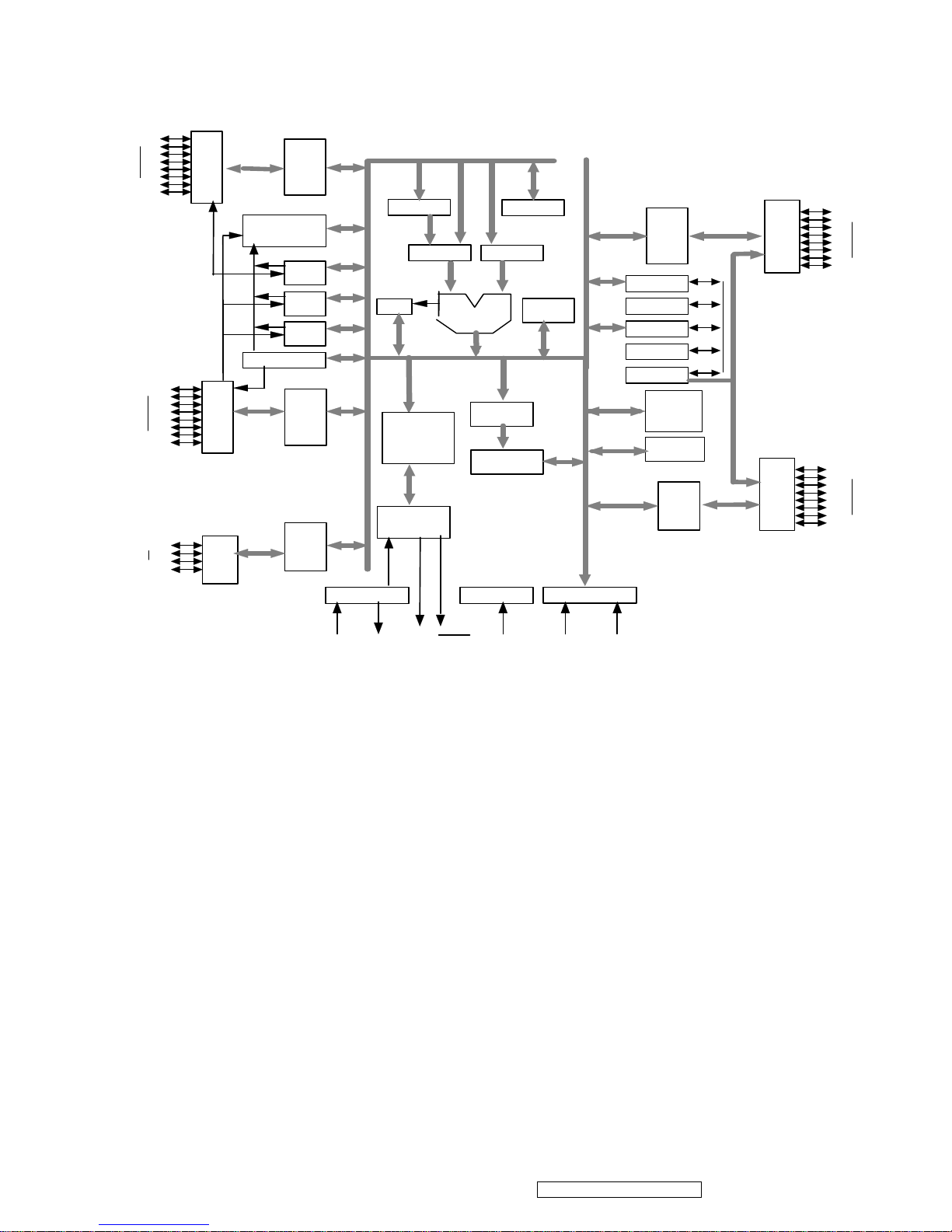
4.4 INTRODUCTION OF IC
MST8011B (U401): integrate ADC, OSD, SCALER, LVDS, convert analog RGB into digital and
room and shrink scaling output to LCD panel.
PIN Function:
9
ViewSonic Corporation Confidential - Do Not Copy VA502mb-1
Page 13
10
ViewSonic Corporation Confidential - Do Not Copy VA502mb-1
Page 14
11
ViewSonic Corporation Confidential - Do Not Copy VA502mb-1
Page 15
AIC1084-33PM (U202): DC power convert, used to 5v convert 3.3v.
RT9164-25PL (U201): DC power convert, used to 5v convert 2.5v.
W78E065A40PL (U601):
The W78E65 is an 8-bit microcontroller which has an in-system programmable Flash EPROM for
firmware updating. The instruction set of the W78E65 is fully compatible with the standard 8052.
The W78E65 contains a 64K bytes of main ROM and a 4K bytes of auxiliary ROM which allows
the contents of the 64KB main ROM to be updated by the loader program located at the 4KB
auxiliary ROM; 256+1K bytes of on-chip RAM; four 8-bit bi-directional and bit-addressable I/O
ports; an additional 4-bit port P4; three 16-bit timer/counters; a serial port. These peripherals are
supported by a eight sources two-level interrupt capability. To facilitate programming and
verification, the ROM inside the W78E65 allows the program memory to be programmed and
read electronically. Once the code is confirmed, the user can protect the code for security.
The W78E65 microcontroller has two power reduction modes, idle mode and power-down mode,
both of which are software selectable. The idle mode turns off the processor clock but allows for
continued peripheral operation. The power-down mode stops the crystal oscillator for minimum
power consumption. The external clock can be stopped at any time and in any state without
affecting the processor.
12
ViewSonic Corporation Confidential - Do Not Copy VA502mb-1
Page 16
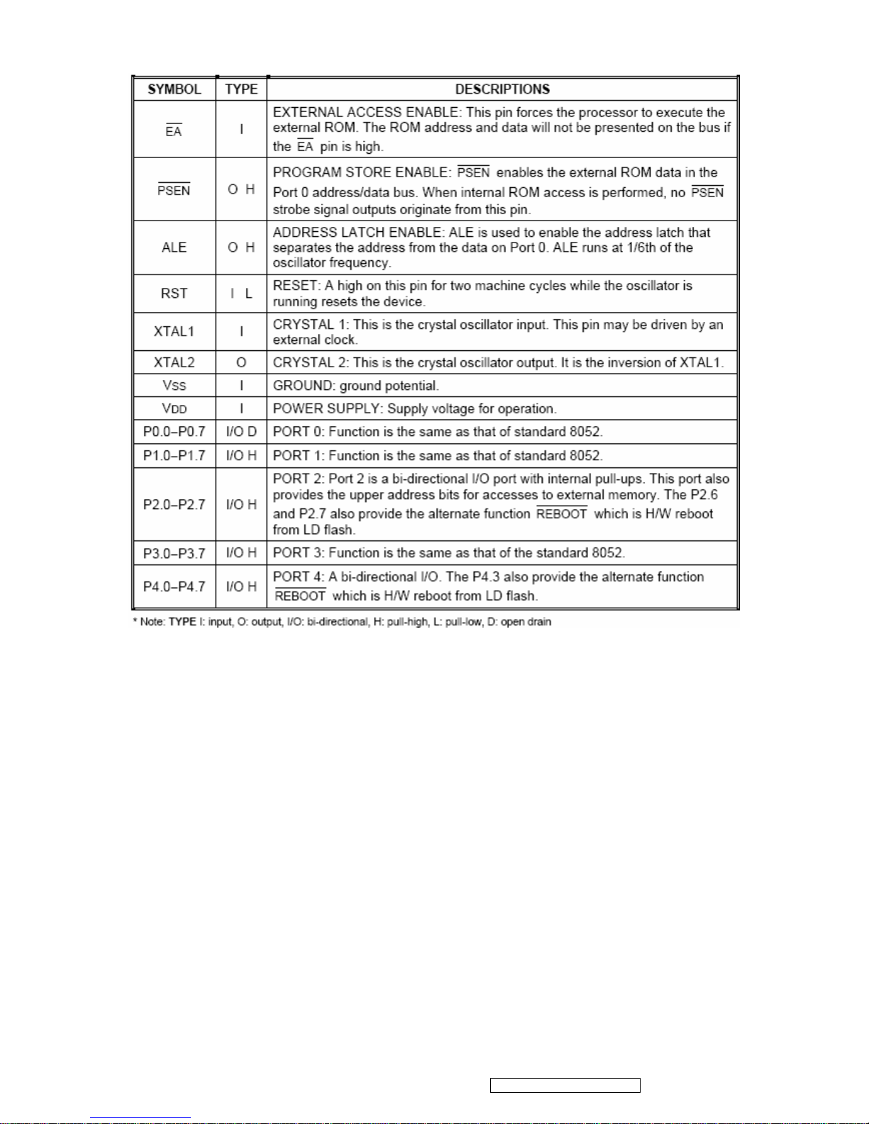
PIN Descriptions:
13
ViewSonic Corporation Confidential - Do Not Copy VA502mb-1
Page 17
Circuit Diagram
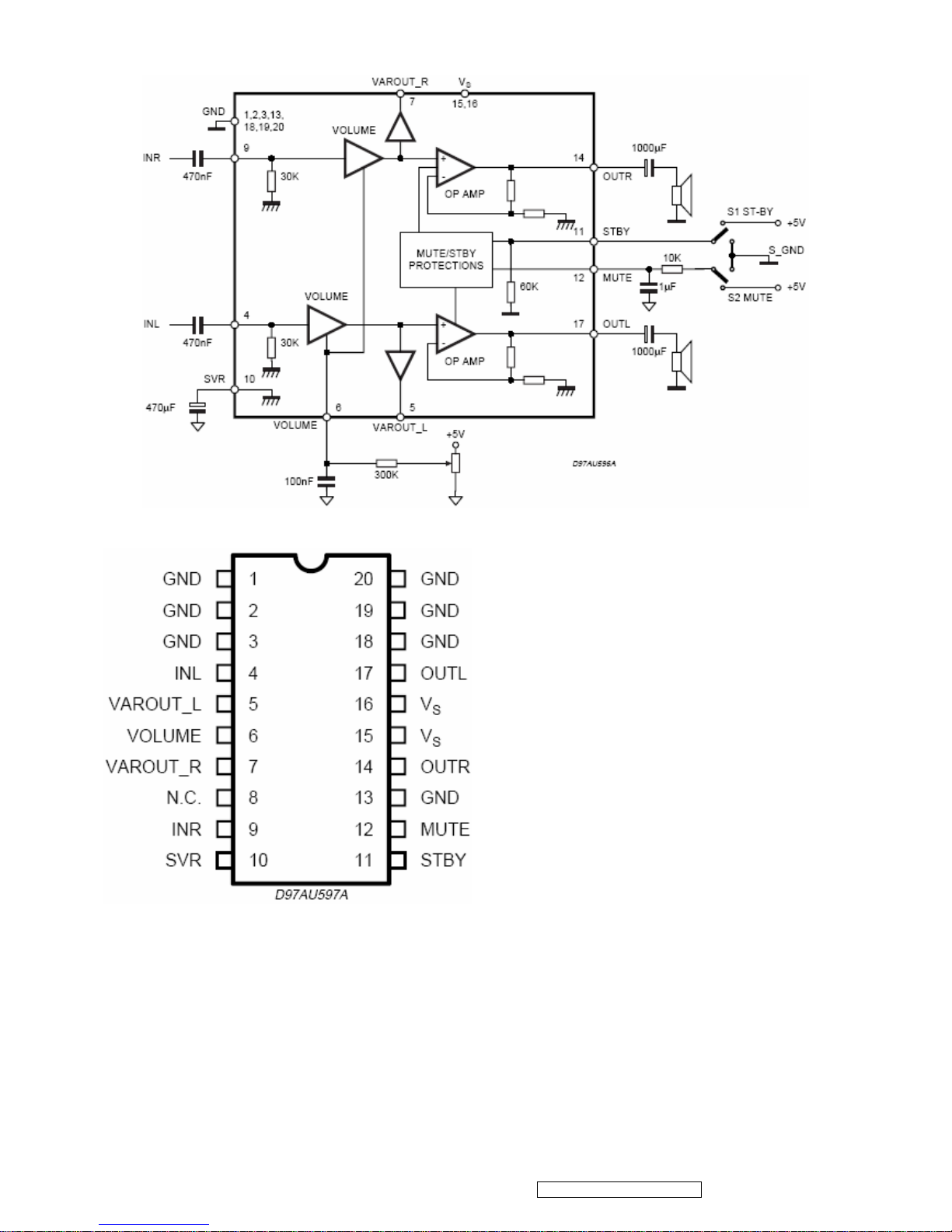
TDA7496(U201): The TDA7496L is a stereo 2W+2W class AB power amplifier assembled in the
@ Powerdip 14+3+3 package, specially designed for high quality sound, TV and Monitor
applications. Features of the TDA7496L include linear volume control, Stand-by and mute
functions. The function of each pin and the inside circuit diagram are as follows:
14
ViewSonic Corporation Confidential - Do Not Copy VA502mb-1
P3.0
P3.7
P1.0
P1.7
ALU
Port 0
Latch
Port 1
Latch
Timer
1
Timer
0
Timer
2
Port
1
UART
XTAL1
PSEN
ALE
Vss
VCC
RSTXTAL2
Oscillator
Interrupt
PSW
Instruction
Decoder
&
Sequencer
Reset Block
Bus & Clock
Controller
SFR RAM
Address
Power control
256+1K bytes
RAM & SFR
Stack
Pointer
B
Addr. Reg.
Incrementor
PC
DPTR
Temp Reg.
T2
T1
ACC
Port 3
Latch
Port 4
Latch
Port
3
Port 2
Latch
P4.0
P4.7
Port
4
Port
0
Port
2
P2.0
P2.7
P0.0
P0.7
64KB
Flash E ROM
4KB
Flash EROM
Page 18
Block Diagram
PIN Function
15
ViewSonic Corporation Confidential - Do Not Copy VA502mb-1
Page 19
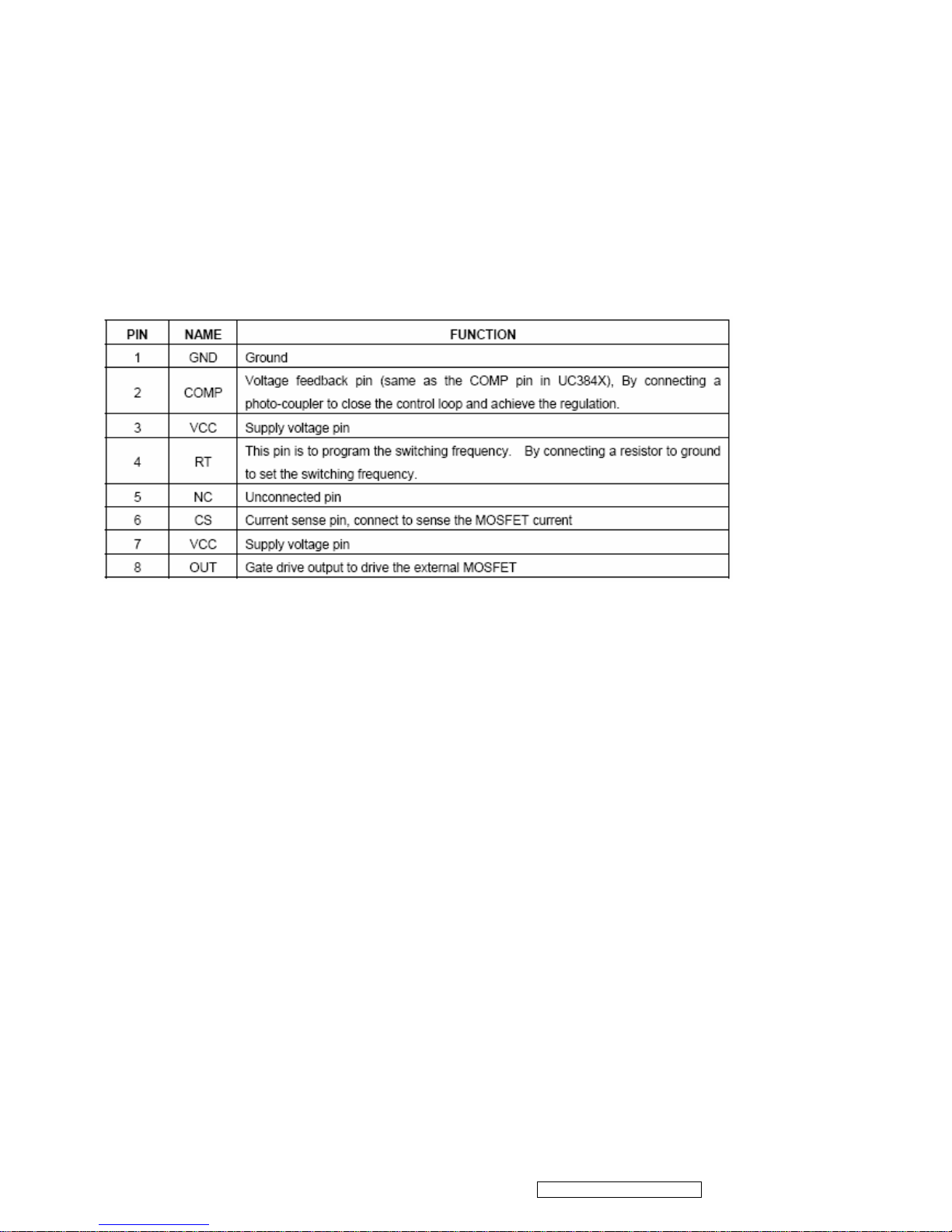
LD7552BPN (IC901): The LD7552B are low cost, low startup current, current
mode PWM controllers with green-mode power- saving operation. The integrated functions
include the leading-edge blanking of the current sensing, internal slope
compensation. They provide the users a superior AC/DC power application of higher efficiency,
low external component counts, and lower cost solution. Furthermore, LD7552B feature more
protections like OLP (Over Load Protection) and OVP (Over Voltage Protection) to eliminate the
external protection circuits. It is designed for the switching adaptor with 30W~60W output,
offered in both SOP-8 and DIP-8 package.
The function of each pin and the inside circuit diagram are as follows:
PIN Descriptions:
16
ViewSonic Corporation Confidential - Do Not Copy VA502mb-1
Page 20

Block Diagram
BA9741F (U201): The BA9741F is a timer latch, short-circuit protection circuit is built in. Circuit
to prevent malfunction during low input voltage is built in. Built-in reference voltage(2.5v)circuit
with output pin. Dead time over the whole range of possible to adjust half period of whole duty
range. Recommendable for regulator in camcorder.
The function of each pin and the circuit diagram inside are as follows:
17
ViewSonic Corporation Confidential - Do Not Copy VA502mb-1
Page 21
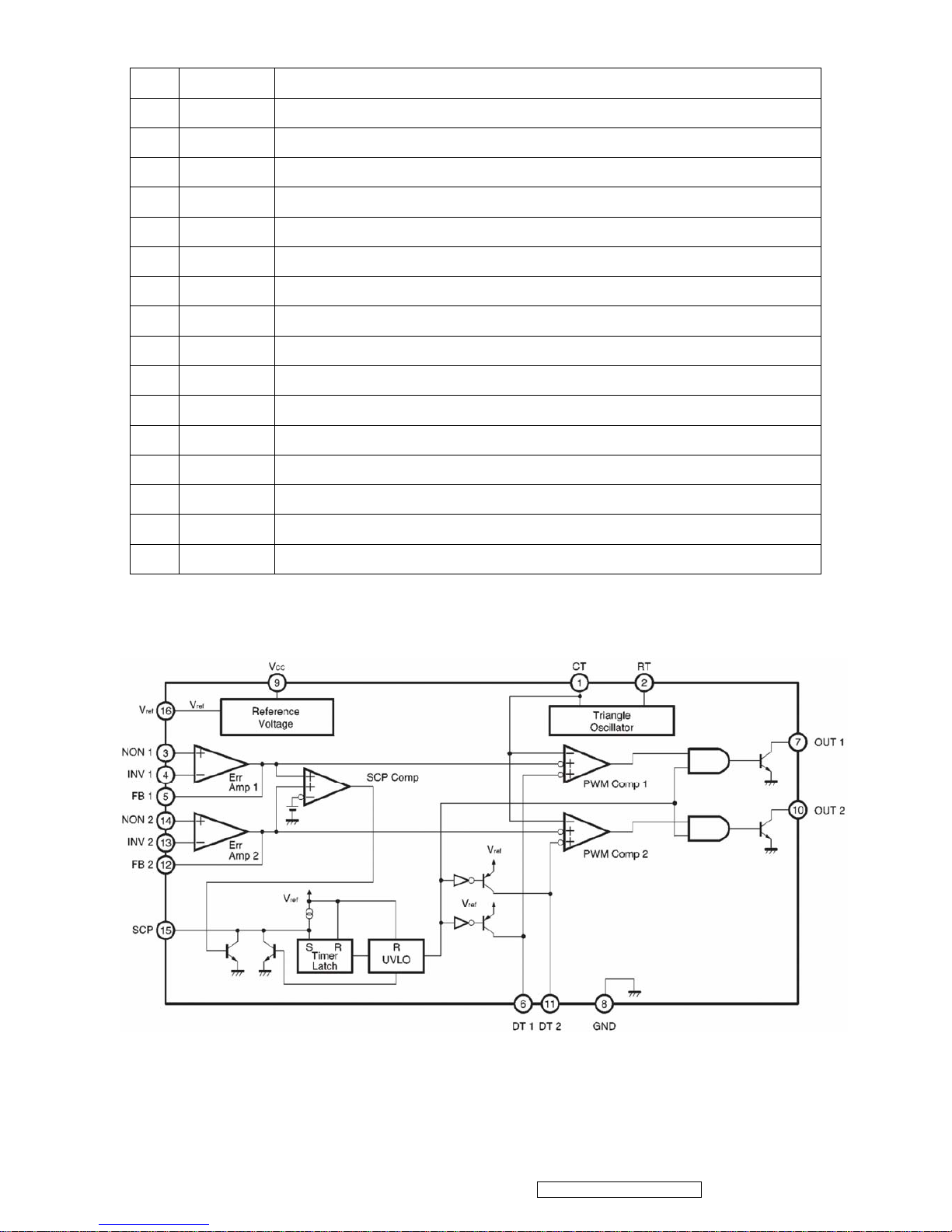
PIN Descriptions:
Pin Names Function
1 CT External timing capacitance
2 RT External timing resistance
3 NON1 Positive input for error amplifier 1
4 INV1 Negative input for error amplifier 1
5 FB1 Output for error amplifier 1
6 DT1 Output 1 dead time/soft start setting
7 OUT1 Output 1
8 GND Ground
9 Vcc Power Supply
10 OUT2 Output 2
11 DT2 Output 2 dead time/soft start setting
12 FB2 Output for error amplifier 2
13 INV2 Negative input for error amplifier 2
14 NON2 Positive input for error amplifier 2
15 SCP Timing latch setting
16 VREF Reference voltage(2.5v) output
18
ViewSonic Corporation Confidential - Do Not Copy VA502mb-1
Block Diagram
Page 22

5. Adjustment Procedure
5.1 ADJUSTMENT CONDITIONS AND PRECAUTIONS
1. Approximately 30 minutes should be allowed for warm up before proceeding.
2. Adjustments should be undertaken only on those necessary elements since most of them
have been carefully preset at the factory.
3. ESD protection is needed before adjustment.
5.2 MAIN ADJUSTMENTS
NO. FUNCTIONS DESIGNATION
1. White Balance Function Key
2. Geometry Function Key
5.3 ALIGNMENT PROCEDURES
Approximately 30 minutes should be allowed for warm up before proceeding
White-Balance adjustment.
1. Adjust of White Balance
1.)How to do the Chroma-7120 MEM .Channel setting
A. Reference to chroma 7120 user guide
B. Use “ SC” key and “ NEXT” key to modify xyY value and use “ID” key to modify the TEXT
description Following is the procedure to do white-balance adjust
2.)Setting the color temp. You want
A. MEM.CHANNEL9 ( 9300 color):
9300 color temp. parameter is Wx = 0.283 ±0.03;Wy = 0.298 ±0.03;
Y = 200 ±20 cd/m
2 ,
B. MEM.CHANNEL10 ( 6500 color):
6500 color temp. parameter is Wx = 0.313±0.03;Wy = 0.329 ±0.03;
Y = 200 ±20 cd/m
2,
C. MEM.CHANNEL10 ( SRGB color):
6500 color temp. parameter is Wx = 0.313±0.03;Wy = 0.329 ±0.03;
Y = 200 ±20 cd/m
2,
19
ViewSonic Corporation Confidential - Do Not Copy VA502mb-1
Page 23

3.) Into factory mode of VA502mb
Turn on power, press the MENU button, pull out the power cord, and then plug the power cord.
Then the factory OSD will be at the left top of the panel.
4.) Bias adjustment:
Set the Contrast
to 70
Adjust the Brightness to 100.
5.) Gain adjustment:
Move cursor to “-F-” and press MENU key
A. Adjust 9300 color-temperature
(1). Switch the Chroma-7120 to RGB-Mode (with press “MODE” button )
(2). Switch the MEM. channel to Channel 9 ( with up or down arrow on chroma 7120 )
(3). The LCD-indicator on chroma 7120 will show x = 0.283 ±0.03, y =0.298 ±0.03,Y = 200 ±
20 cd/m
2
(4). Adjust the RED of color1 on factory window until chroma 7120 indicator reached the
value R=100
(5). Adjust the GREEN of color1 on factory window until chroma 7120 indicator reached the
value G=100
(6). Adjust the BLUE of color1 on factory window until chroma 7120 indicator reached the
value B=100
(7). Repeat above procedure ( item 4,5,6) until chroma 7120 RGB value meet the
tolerance =100±5
B. Adjust 6500 color-temperature
(1). Switch the chroma-7120 to RGB-Mode (with press “MODE” button )
(2). Switch the MEM .channel to Channel 10( with up or down arrow on chroma 7120 )
(3). The LCD-indicator on chroma 7120 will show x = 0.313 ±0.03, y = 0.329 ±0.03, Y = 200 ±
20 cd/m
2
(4). Adjust the RED of color3 on factory window until chroma 7120 indicator reached the
value R=100
(5). Adjust the GREEN of color3 on factory window until chroma 7120 indicator reached the
value G=100
(6). Adjust the BLUE of color3 on factory window until chroma 7120 indicator reached the
value B=100
(7). Repeat above procedure ( item 4,5,6) until chroma 7120 RGB value meet the
tolerance =100±5
20
ViewSonic Corporation Confidential - Do Not Copy VA502mb-1
Page 24

C. Adjust SRGB color-temperature
(1). Switch the chroma-7120 to RGB-Mode (with press “MODE” button )
(2). Switch the MEM .channel to Channel 10( with up or down arrow on chroma 7120 )
(3). The LCD-indicator on chroma 7120 will show x = 0.313 ±0.03, y = 0.329 ±0.03, Y = 200 ±
20 cd/m
2
(4). Adjust the RED of color3 on factory window until chroma 7120 indicator reached the
value R=100
(5). Adjust the GREEN of color3 on factory window until chroma 7120 indicator reached the
value G=100
(6). Adjust the BLUE of color3 on factory window until chroma 7120 indicator reached the
value B=100
(7). Repeat above procedure ( item 4,5,6) until chroma 7120 RGB value meet the tolerance
=100±5
E. Press reset key and Turn the Power-button “off to on” to quit from factory mode.
2. Geometry
1).Set cross-hatch pattern and preset timing as timing table listed.
2).Change to each mode in turn and wait for the monitor finish auto-alignment and save press
before change to next mode.
3).Until all of modes are adjusted, exit OSD menu and press POWER OFF to exit factory mode.
5.4 Factory Defaults
Item Defaults Item Defaults
Contrast 70% Volume 50%
(For VA702mb only)
Brightness 100% Balance N/A
Color Temperature 6500K Treble N/A
Sharpness 0% Bass N/A
OSD H. Position 50% 720x400/640x400 720x400
OSD V. Position 50% 640x480@60Hz
720x480@60Hz
640x480@60Hz
OSD Time Out 15 Sec In SOG and Composite,
720x480@60Hz
640x480@60Hz
N/A
OSD Background Enabled In SOG and Composite,
1152x864@75Hz
1152x870@75Hz
N/A
Resolution Notice Enabled In SOG and Composite,
1280x768@60/75/85Hz
1024x768@60/75/85Hz
N/A
21
ViewSonic Corporation Confidential - Do Not Copy VA502mb-1
Page 25

5.5 Function Test
1 Product: 17” LCD Monitor
2 Test Equipment: Color Video Signal & Pattern (or PC with SXGA resolution and a sound card)
3 Test Condition: Before function test and alignment, each LCD Monitor should be warmed up for
at least 30 minutes with the following conditions:
(a)In room temperature,
(b) With full-white screen, RGB, and Black
(c) With cycled display modes,
640*480 (H=43.27kHz, V=85Hz)
800*600 (H=53.7kHz, V=85Hz)
1024*768 (H=68.67kHz, V=85Hz)
1280*1024 (H=79.97kHz, V=75Hz)
4 Test Display Modes & Pattern
Compatible Modes
Item Timing Analog
1 640 x 350 @ 70Hz, 31.5kHz
Yes
2 640 x 480 @ 50Hz
Yes
3 640 x 480 @ 60Hz, 31.5kHz
Yes
4 640 x 480 @ 67Hz, 35.0kHz
Yes
5 640 x 480 @ 72Hz, 37.9kHz
Yes
6 640 x 480 @ 75Hz, 37.5kHz
Yes
7 640 x 480 @ 85Hz, 43.27kHz
Yes
8 720 x 400 @ 70Hz, 31.5kHz
Yes
9 800 x 600 @ 56Hz, 35.1kHz
Yes
10 800 x 600 @ 60Hz, 37.9kHz
Yes
11 800 x 600 @ 72Hz, 48.1kHz
Yes
12 800 x 600 @ 75Hz, 46.9kHz
Yes
13 800 x 600 @ 85Hz, 53.7kHz
Yes
14 832 x 624 @ 75Hz, 49.7kHz
Yes
15 1024 x 768 @ 60Hz, 48.4kHz
Yes
16 1024 x 768 @ 70Hz, 56.5kHz
Yes
17 1024 x 768 @ 72Hz, 58.1kHz
Yes
18 1024 x 768 @ 75Hz, 60.0kHz
Yes
19 1024 x 768 @ 85Hz
Yes
20 1152 x 864 @ 75Hz
Yes
21 1152 x 870 @ 75Hz
Yes
22 1280 x 720 @ 60Hz
Yes
23 1280 x 960 @ 60Hz
Yes
24 1280 x 960 @75Hz
Yes
25 1280 x 1024 @ 60Hz
Yes
26 1280 x 1024 @ 75Hz
Yes
22
ViewSonic Corporation Confidential - Do Not Copy VA502mb-1
Page 26

Function Test Display Pattern
Item Test Content Pattern Specification Remark
1
Frequency &
Tracking
Fine Line Moire Eliminate visual wavy noise. Figure 1
2
Contrast/Brigh
tness
16 Gray Scale
16 gray levels sh should be
distinguishable.
Figure 2
3 Boundary
Horizontal&Vertical
Thickness
Horizontal and Vertical position
of video should be adjustable to
be within the screen frame.
Figure 3
4
RGB Color
Performance
RGB Color Intensities
Contrast of each R, G, B, color
should be normal.
Figure
4,5,6
5
Screen
Uniformity &
Flicker
Full White
Should be compliant with the
spec.
Figure 7
6
Dead
Pixel/Line
White Screen & Dark
Screen
The numbers of dead pixels
should be compliant with the
spec.
Figure 7,8
7 White Balance White & Black Pattern
The screen must have the pure
white and black pattern, no
other color.
Figure 9
23
ViewSonic Corporation Confidential - Do Not Copy VA502mb-1
Page 27

Fine Line Morie Pattern (Figure1) Gray Scale Pattern (Figure2)
Horizontal & Vertical Thickness Pattern
(Figure 3)
R. Color Pattern (Figure 4)
G. Color Pattern (Figure 5 B. Color Pattern (Figure 6)
24
ViewSonic Corporation Confidential - Do Not Copy VA502mb-1
Page 28

Full White Pattern (Figure 7) Dark Screen Pattern (Figure 8)
Black-White Pattern (Figure 9)
4.3 Function Test and Alignment Procedure
All Modes Reset
You should do “All Mode Reset” (Refer to Chapter III-3. Hot Keys for Function Controls)
first. This action will allow you to erase all end-user’s settings and restore the factory
defaults.
Auto Image Adjust
Please select and enter “Auto Image Adjust” function on Main Menu to see if it is workable.
The “Auto Image Adjust” function is aimed to offer a better screen quality by built-in ASIC.
For optimum screen quality, the user has to adjust each function manually.
Firmware
Test Pattern: Burn In Mode (Refer to Chapter III-3. Hot Keys for Function Controls)
- Make sure the F/W is the latest version.
DDC
Test Pattern: EDID program
Make sure it can pass test program.
25
ViewSonic Corporation Confidential - Do Not Copy VA502mb-1
Page 29

Fine Tune and Sharpness
Test Signal: 1280*1024@60Hz
Test Pattern: Line Moire Pattern
Check and see if the image has noise and focus performs well. Eliminate visual line bar.
If not, readjust by the following steps:
(a)Select and enter “Fine Tune” function on “Manual Image Adjust” to adjust the image to
eliminate visual wavy noise.
(b)Then, select and enter “Sharpness” function to adjust the clarity and focus of the screen
image.
Boundary
Test Signal: 1280*1024@60Hz
Test Pattern: Horizontal & Vertical Line Thickness Pattern
Check and see if the image boundary is within the screen frame.
If not, readjust by the following steps:
(a)Select and enter “Manual Image Adjust” function on OSD Main Menu.
(b)Then, select and enter “Horizontal Size” or “Horizontal/Vertical Position” function to
adjust the video boundary to be full scanned and within screen frame.
White Balance
Test Signal: 640*480@60Hz
Test Pattern: White and Black Pattern
1.5.8 R, G, B, Colors Contrast
Test Signal: 1280*1024@60Hz
Test Pattern: R, G, B, Color Intensities Pattern and 16 Gray Scale Pattern
- Check and see if each color is normal and distinguishable.
- If not, please return the unit to repair area.
Screen Uniformity and Flicker
Test Signal: 1280*1024@60Hz
Test Pattern: Full White Pattern
- Check and see if it is in normal condition.
1.5.10 Dead Pixel and Line
Test Signal: 1280*1024@60Hz
Test Pattern: Dark and White Screen Pattern
- Check and see if there are dead pixels on LCD panel with shadow gauge and filter film.
- The total numbers and distance of dead pixels should be compliant with the spec.
Mura
Test Pattern: White, RGB, Black, & Grey
Test Tool: 10% ND Filter
- Check if the Mura can pass 10% ND Filter.
26
ViewSonic Corporation Confidential - Do Not Copy VA502mb-1
Page 30

Audio
Test Signal: Voice signal (optional, depend on model)
Test Pattern: liberty
- Make sure there is audio output.
- Make sure that audio function (volume 80%) is working without noise and resonance.
- Make sure that the sound of right and left speakers are in balance.
Check for Secondary Display Modes
Test Signal:
Analog: 640*350@70Hz; 640*480@60/67/72/75/85Hz;
720*400@70Hz; 800*600@56/60/72/75/85Hz;
832*624@75Hz, 1024*768@60/70/72/75/85Hz;
1280*1024@60/75Hz
- Normally when the primary mode 1280*1024@60Hz is well adjusted and compliant
with the specification, the secondary display modes will also be compliant with the spec.
But we still have to check with the general test pattern to make sure every secondary is
compliant with the specification.
All Modes Reset
After final QC step, we have to erase all saved changes again and restore the factory
defaults. You should do “All Mode Reset” again.
Power Off Monitor
Turn off the monitor by pressing “Power” button.
27
ViewSonic Corporation Confidential - Do Not Copy VA502mb-1
Page 31

5.6 Firmware Upgrade Procedure
When you receive the returned monitor, please check whether the firmware version is the latest.
If not, please do the following procedures to upgrade it to the latest version.
1 Equipment Needed
- VA502mb/VA702mb Monitor
- Fixture for Firmware Upgrade
- Power Adapter (P/N: 47.58201.001) *1 for Fixture
- VGA Cable (P/N: 42.59901.003) *1(Pin 4, 11 should be connected to GND)
- PC (Personal Computer)
- LPT Cable (P/N: 42.59906.001) *1
- Firmware Upgrade Program
- One additional monitor for checking the program execution
28
ViewSonic Corporation Confidential - Do Not Copy VA502mb-1
Page 32

2 Setup Procedure
2.1 Connect P2 of Fixture with printer port of PC by LPT Cable.
2.2 Connect P1 of Fixture with VA502mb/VA702mb Monitor by VGA Cable.
2.3 Plug Power Adapter to Fixture.
2.4 Connect Power Cord to VA502m/VA702mb Monitor.
2.5 Connect P3 to the Signal Generator (eg.Chroma2326) for verifying it after the operation
being completed.
2.6 Connect PC to the additional monitor.
P2:to LPT Cable
:
P1:to VGA Cable
P3:to Signal Generator
3 Firmware Upgrade Procedure
Step 1. Let VA502mb/VA702mb set to be connected with AC cable and VGA cable.
Step 2.Execute the MSstar ISP tool.
29
ViewSonic Corporation Confidential - Do Not Copy VA502mb-1
Page 33

Step 3. Click “Config” button . Select the Port Type: LPT1 and the Base Addr : 0x378 on
“Communication Setting” flame, and then the Speed: 47 on “E2PROM Device Setting” flame
Step 4. Click “Connect” button. (On this step, if the connection is successful, the “Entry ISP
Mode” Dialog will be showed. If not, the error dialog will be done.)
Step 5. Click “Device” button. Select the “PMC25LV010” or “SST25VF010” viewed on your set.
30
ViewSonic Corporation Confidential - Do Not Copy VA502mb-1
Page 34

Step 6. Click “Read” button. Select the object bincode on your corresponding directory.
Step 7. Click “Auto” button. Execute the flashing action by clicking the “Run” button.
Step 8. If the flashing F/W has been completed, “Ok” message will be showed on the right
TextBox.
31
ViewSonic Corporation Confidential - Do Not Copy VA502mb-1
Page 35

Step 9. Unplug and replug power cord of VA502mb/VA702mb set and then check the OSD
operation and image on srceen.
Step 10. At last, do “Memory Recall.”
3.2 Setup Procedure
3.2.1 Connect P2 and monitor of Fixture with VGA ports of VA502mb/VA702mb by VGA
Cable.
3.2.2 Connect P1 of Fixture with Printer port of PC by LPT Cable.
3.2.3 Plug Power Adapter to Fixture.
3.2.4 Connect Power Cord to VA502mb/VA702mb Monitor.
3.2.5 Connect PC to the additional monitor.
P1:to LTP Cable
P2: VGA Cable
JP1: Power Adapter
32
ViewSonic Corporation Confidential - Do Not Copy VA502mb-1
Page 36

3.3 DDC Key In Procedure
Sep1.Select and execute DDc Key In program
Sep2:Inpute the S/N and execute “Enter”
33
ViewSonic Corporation Confidential - Do Not Copy VA502mb-1
Page 37

Sep3: Key the “Enter” and write the data
Sep4: If ddc program OK and show “data compare ok”
34
ViewSonic Corporation Confidential - Do Not Copy VA502mb-1
Page 38

5.7 Packing Procedure
35
ViewSonic Corporation Confidential - Do Not Copy VA502mb-1
Page 39

7.1 Units Disassemble Process
7.1.1 Tools
Glove
Big cross screwdriver
Small cross screwdriver
Prize equipment or abandoned IC card
Screw box
Cushion
Six angle sleeve spanner
7.1.2 Disassemble process
1、 The whole monitor.(Picture 1)
2、 Remove the decorate slice and the stand.(Picture 2, 3)
3、 Disassemble the 4 screws that fix the back cover, remove the back cover. (Picture 4)
4、 Disassemble the shield and remove the aluminum foil .(Picture 5,6)
5、 Disassemble the screws for main board, power board, audio board and the connector or
wire. (Picture 7,8)
6、 Disassemble the screws for the shielding. (Picture 9,10)
7、 The panel. (Picture 11)
7.1.3 Show pictures
(Picture 1) (Picture 2)
36
ViewSonic Corporation Confidential - Do Not Copy VA502mb-1
Page 40

(Picture 3) (Picture4)
(Picture 5) (Picture 6)
(Picture 7)
37
ViewSonic Corporation Confidential - Do Not Copy VA502mb-1
Page 41

(Picture 8)
(Picture 9)
(Picture 10)
(Picture11)
38
ViewSonic Corporation Confidential - Do Not Copy VA502mb-1
Page 42

39
ViewSonic Corporation Confidential - Do Not Copy VA502mb-1
6. Troubleshooting Flow Chart
Page 43

7. Block Diagram
40
ViewSonic Corporation Confidential - Do Not Copy VA502mb-1
Page 44

8. Schematic Diagrams
VAA1
B1
3.INPUT
RIN
GIN
BIN
VSYNC
GNDR
GNDG
GNDB
ST_DET1 HSYNC
SOGDDC_CLK
DDC_DAT
ST_DET2
R+
R-
G-
G+
B+
B-
CLK+
CLK-
TXD
RXD
PA[0..9]
VAA2
TSU16AK SCHEMATIC
VLCD
VCC2.5
VCC5V
VCC12V
VCPU VCC12V
VAA4
VAA3
VAA1
VAA3VCC2.5
VCC3.3
B3
6.MCU
onBACKLITE
ST_DET2
onPANEL_5V/3.3V
SDA
INT
CSZ
DDC_DAT
ST_DET1
SCL
HWRESET
DDC_CLK
Volume
VCC5V
VCC12V
VCPU
RXD
TXD
AD0
AD1
AD2
AD3
VCC5V
B5
5.PANEL INTERFACE
VLCD
PB[0..9]
PA[0..9]
VAA4
PB[0..9]
VLCD
B4
2.POWER
onPanel_5V/3.3V
onBACKLITE
AdjBACKLITE
VCC3.3
VCC2.5
VAA1
VAA2
VAA3
VAA4
VCC5V
VCC12V
VLCD
VCPU
B2
4.SCALER
RIN
GIN
GNDR
SOG
GNDG
BIN
GNDB
VCC3.3
HSYNC
VSYNC
R+
R-
G-
G+
B+
BCLK+
CLK-
CSZ
SCL
SDA
HWRESET
INT
Volume
AdjBACKLITE
PA[0..9]
PB[0..9]
VCC2.5
VCC3.3
VAA1
VAA2
VAA3
VAA4
AD0
AD1
AD2
AD3
VCPU
VAA2
41
ViewSonic Corporation Confidential - Do Not Copy VA502mb-1
Model
Title
Date Rev:
ViewSonic Corporation
MAIN BOARD
Page 45

C201
0.1uF
Q204
PMBS3904
32
1
VAA4
C217
0.068uF
R211
10KΩ 1/16W
SOT-252
VCC5V+
C212
0.1uF
VAA3 4
R208
10KΩ 1/16W
CN201
CONN
2
4
6
8
10
12
1
3
5
7
9
11
C
BE
VCC5V
VCC12V
R212 4.7KΩ 1/16W
VCC3.3
R210
NC
VCC5V
C205
0.1uF
VAA1 4
onPanel_5V/3.3V6
C210
0.1uF
VCC12V
NEW
Circuit
VCC12V
VCC5V
R202
10KΩ 1/16W
R209
0Ω 1/16W
VAA2 4
VCC5V
FB201
600 OHM
GND
+
C204
220uF/25V
GND
D201 SS14
VLCD 5
+
C208
100uF/16V
R216
4.7KΩ 1/16W
R214 delete
VCC5V+
VCC5V
C203
0.1uF
VAA3
VCC5V
+
C211
47uF/16V
U202
AIC1084-33M
3
1
2
VIN
ADJ
VOUT
R201 4.7KΩ 1/16W
TO-263
VAA4 4
R205 4.7KΩ 1/16W
AdjBACKLITE4
VCC5V+
+
C202
220uF/25V
D202
GS1D
VCC12V
C216
0.1uF
VCC5V
GND DIM
VCC5V
C207
0.1uF
VAA2C214
0.1uF
VAA1
Q202
PMBS3904
32
1
VCC3.3
R207
4.7KΩ 1/16W
R204
10KΩ 1/16W
VCPU
C
BE
GND
R206
10KΩ 1/16W
C206
1uF/25V
Brightness
R213
NC
VCC2.5 4
U201
RT9164
3 2
1
VI VO
GND
VCC3.3 4
VCC5V 3,4,6
R203
1KΩ 1/16W
VCC12V 6
VCC2.5
VLCD
R215
100KΩ 1/16W
+
C215
47uF/16V
VCPU 6
ON_OFF
GND
GND
3
Q201
PMBS3904
2
1
onBACKLITE 6
Q203
AO3401
42
ViewSonic Corporation Confidential - Do Not Copy VA502mb-1
Model
Title
Date Rev:
ViewSonic Corporation
POWER
Page 46

43
ViewSonic Corporation Confidential - Do Not Copy VA502mb-1
B- 4
D306
BAV99
3
1
2
R321
10KΩ 1/16W
R315 100Ω 1/16W
R319 100Ω 1/16W
GNDR 4
PC5V
VSI
R310 1KΩ 1/16W
ST_DET2 6
DAT_DDC
U302
M24C02WMN6
1
2
3
45
6
7
8
A0
A1
A2
GNDSDA
SCL
WP
VCC
HSI
DVI5V
R303 100Ω 1/16W
D312
BAV99
3
1
2
PC5V
C308 0.047uF
FB303 0Ω 1/16W
R309 100Ω 1/16W
R- 4
GIN 4
D323
TZMC5V6-GS08
ST_DET1 6
D311
BAV99
3
1
2
R327
75Ω 1/16W
D318
TZMC5V6-GS08
CLK+ 4
R324
10KΩ 1/16W
R318
10KΩ 1/16W
C310 0.047uF
C304 0.047uF
R308
10KΩ 1/16W
D315
LL5232B 5.6V 5%
G+ 4
VGA_CON
GNDB 4
VCC5V
RXD 6
CLK_DDC
DDC_DAT6
D316
LL5232B 5.6V 5%
R317
10KΩ 1/16W
R304 470Ω 1/16W
D301
BAV99
3
1
2
D309
BAV99
3
1
2
BIN 4
FB304 150 OHM
R316 100Ω 1/16W
R+ 4
VCC5V
C315
0.1uF
FB301 0Ω 1/16W
C305 0.047uF
D302
BAV99
3
1
2
U301
M24C02WMN6
1
2
3
45
6
7
8
A0
A1
A2
GNDSDA
SCL
WP
VCC
RIN 4
CN301
DB15
1
6
2
7
3
8
4
9
5
11
12
13
14
15
10
C309 0.047uF
R313
2.2KΩ 1/16W
D303
BAV99
3
1
2
VCC5V
R307 100Ω 1/16W
D313
BAV99
3
1
2
FB302 0Ω 1/16W
R312 100Ω 1/16W
CLK- 4
D310
BAV99
3
1
2
D305
BAV70
1
2
3
TXD 6
R306 100Ω 1/16W
D307
BAV99
3
1
2
R320 100Ω 1/16W
GNDG 4
VCC5V
C314
0.1uF
SOG 4
DVI5V
VSYNC 4
DDC_CLK6
D317
TZMC5V6-GS08
R305 100Ω 1/16W
C302
NC
VCC5V
R302 100Ω 1/16W
R326
75Ω 1/16W
HSYNC 4
D314
LL5232B 5.6V 5%
R314
10KΩ 1/16W
R323
10KΩ 1/16W
R322 100Ω 1/16W
R311 1KΩ 1/16W
D322
TZMC5V6-GS08
D321
TZMC5V6-GS08
C312
220pF
C306 0.047uF
R325
75Ω 1/16W
CLK_DDC2
D320
TZMC5V6-GS08
D304
BAV70
1
2
3
C301
NC
CN302
JACK
1
2
3
4
5
6
7
8
25
28
9
10
11
12
13
14
15
16
26
29
17
18
19
20
21
22
23
24
27
DAT2-
DAT2+
2/4shield
DAT4-
DAT4+
DDC SCL
DDC SDA
VSYNC
R
HSYNC
DAT1-
DAT1+
1/3shield
DAT3-
DAT3+
+5V
SYNC GND
HPD
G
RGB GND
DAT0-
DAT0+
0/5shield
DAT5-
DAT5+
clk shield
clk+
clk-
B
R301 100Ω 1/16W
C303
NC
B+ 4
D319
TZMC5V6-GS08
D308
BAV99
3
1
2
G- 4
DAT_DDC2
C313
0.1uF
C307 0.001uF
C311
33pF
Model
Title
Date Rev:
ViewSonic Corporation
INPUT
Page 47

44
ViewSonic Corporation Confidential - Do Not Copy VA502mb-1
SCL6
4.7K
FB401
600 OHM
G+3
GNDB3
PA[0..9]
R401
NC
C407
0.1uF
4.7K
VDPLL
PA6
AD0 6
B+3
PB3
R405
10KΩ 1/16W
G-3
R407
10KΩ 1/16W
R401
PB0
VPO
C411
0.1uF
BIN3
R403 390Ω 1/16W
+
C414
10uF/16V
AD3 6
FB404
600 OHM
C421
0.1uF
RIN3
+
C427
10uF/16V
U401
63
60
61
58
62
59
57
37
38
40
41
43
44
46
47
49
50
52
66
67
69
70
71
32
72
73
74
107
55354535111218494
104
114
126188797117
3956362544210208595115
1271986
96
105
116
33
34
108
109
110
111
112
113
118
119
120
121
122
123
124
125
128
1
29
28
30
31
53
65
64
48
106
103
102
68
77
78
6
RIN0
GIN0
SOGIN0
BIN0
RIN0M
GIN0M
BIN0M
HSYNC0
VSYNC0
R+
RG+
GB+
BCK+
CKREXT
REFP
REFM
CSZ
SDA
SCL
HWRESETZ
INT
PWM0
PWM1
LVACKM
AVDD
AVDD_MPLL
AVDD_DVI
BYPASS
AVDD_DVI
VDDP
VDDP
VDDP
VDDP
VDDP
VDDP
VDDP
VDDC
VDDC
VDDC
VDDC
AVSS_DVI
AVSS
AVSS_MPLL
AVSS_LPLL
AVSS_PLL
AVSS_DVI
GNDP
GNDP
GNDP
GNDP
GNDP
GNDP
GNDC
GNDC
GNDC
GNDP
GNDC
XIN
XOUT
LVA2P
LVA2M
LVA1P
LVA1M
LVA0P
LVA0M
NC/LVB3P
NC/LVB3M
NC/LVBCKP
NC/LVBCKM
NC/LVB2P
NC/LVB2M
NC/LVB1P
NC/LVB1M
NC/LVB0P
NC/LVB0M
DDC1_CLK/GPO8
DDC1_DAT/GPO7
ADO/NC
AD3/NC
AVDD_PLL
AVDD
AVSS
AVSS_DVI
LVACKP
LVA3M
LVA3P
AVSS
AD1/NC
AD2/NC
BUS TYPE/NC
Volume6
FB406
600 OHM
VAD
C428
0.1uF
Direct Bus
VAD VDD
PB2
R406
10KΩ 1/16W
PB[0..9] 5
C418
0.1uF
R+3
PA0
C415
0.1uF
+
C424
10uF/16V
INT6
PB4
VCC2.52
PB7
B-3
+
C422
10uF/16V
C420
0.1uF
R404
10KΩ 1/16W
VAA3
FB403
600 OHM
CSZ6
VAA1
C406
0.1uF
HWRESET6
VCC5V
VPLL
+
C405
10uF/16V
PA8
PA7
GIN3
PA1
C417
0.1uF
VAA42
VAA32
3-WIRE
VDPLL
C401
0.1uF
AdjBACKLITE2
PB[0..9]
R402
100Ω 1/16W
C410
0.1uF
C402 22pF
NC
C412
0.1uF
VDVI
+
C419
10uF/16V
AD1 6
TSU16AK
VPO
VDVI
C413
0.1uF
PB5
VSYNC3
PA[0..9] 5
SOG3
VAA12
VDVI
R402
HSYNC3
C423
0.1uF
GNDG3
VCC3.3
GNDR3
FB402
600 OHM
VCC3.32
PA5
VCC2.5
FB405
600 OHM
C416
0.1uF
AD2 6
VAA4
PA3
NC
VCC3.3
VAA2
C426
0.1uF
VPLL
PA4
PB6
VAA22
PA9
R-3
VDD
PB9
CLK+3
CLK-3
C408
0.1uF
C404 0.1uF
C425
0.1uF
SDA6
PB1
PA2
PB8
X401
14.318MHz
C403 22pF
C409
0.1uF
Model
Title
Date Rev:
ViewSonic Corporation
SCALER
Page 48

VLCD 2
LVA0M
LVB3P
LVB2M
LVA0P
PA1
VLCD
LVA1M
CN503
CONN
2
4
6
8
10
12
14
16
18
20
22
24
1
3
5
7
9
11
13
15
17
19
21
23
LVA3M
LVB1M
LVB0P
PA7
LVB2M
RXE2+
LVB0P
C511
0.1uF
LVA1P
LVB1P
LVA2P
PA3
RXE0+
RXE3+
PA0
LVB2P
RXE2-
PA2
LVA2M
PB1
RXEC-
PA6
PA5
LVACKP
LVA2M
LVBCKM
RXO0-
+
C509
47uF/16V
LVA2P
RXO2+
PB9
RXO2RXOC-
LVBCKP
PB4
LVB0M
LVA3M
RXEC+
LVB1P
RXO3+
PB2
RXE1-
PA[0..9]
LVA1M
PB3
LVB3M
RXE1+
LVB3P
LVA0M
LVB0M
LVACKM
RXOC+
RXO1+RXO1-
LVA3P
RXE0-
PA[0..9]4
R502
0Ω 1/16W
LVB1M
PA9
PB[0..9]
LVA1P
LVB3M
LVB2P
PB5
RXE3-
LVACKM
PA8
RXO0+
PB7
LVACKP
LVA0P
RXO3-
LVBCKM
PB0
LVA3P
PA4
PB8
LVBCKP
PB6
PB[0..9]4
C510
0.1uF
45
ViewSonic Corporation Confidential - Do Not Copy VA502mb-1
Model
Title
Date Rev:
ViewSonic Corporation
PANEL INTERFACE
Page 49

46
ViewSonic Corporation
Confidential - Do Not Copy VA502mb-1
VCPU
OUT-R-
R613
10KΩ 1/16W
onBACKLITE 2
R625 10KΩ 1/16W
LED_O
AD0 4
VCPU
R614 10KΩ 1/16W
R634 100Ω 1/16W
R618
120Ω 1/16W
R601
10KΩ 1/16W
U601
W78E65P-40
35
21
20
10
14
15
16
17
2
3
4
5
6
7
8
9
43
42
41
40
39
38
37
36
24
25
26
27
28
29
30
31
19
18
32
33
13
11
22 44
12
EA/VP
XTAL1
XTAL2
RESET
INT0/P3.2
INT1/P3.3
T0/P3.4
T1/P3.5
P1.0
P1.1
P1.2
P1.3
P1.4
P1.5
P1.6
P1.7
P0.0
P0.1
P0.2
P0.3
P0.4
P0.5
P0.6
P0.7
P2.0
P2.1
P2.2
P2.3
P2.4
P2.5
P2.6
P2.7
P3.7/RD
P3.6/WR
PSEN
ALE/P
P3.1/TXD
P3.0/RXD
VSS VCC
P4.3
Q602
PMBS3906
3 2
1
VCC5V 2,3,4
onPANEL_5V/3.3V 2
LED_B
FB602 600 OHM
Reset
Circuit
POWER
R643
NC
LED_ORANGE
OUT-L+
R638 NC
ENTER
C618
0.1uF
R640
NC
FB603
600 OHM
C612
0.1uF
R623 470Ω 1/16W
VCPU
VCPU
Standby
LEFT
R624 470Ω 1/16W
VCPU2
X601
20MHz
CSZ 4
C616
1uF/25V
RIGHT
C617
100pF
+
C603
10uF/16V
C607
0.001uF
C613
0.1uF
Mute_key
RN602
10KΩ 1/16W
123
4
876
5
CN602
CONN
2
4
6
8
10
12
14
16
1
3
5
7
9
11
13
15
R616
4.7KΩ 1/16W
R617
120Ω 1/16W
Mute_key
R629
4.7KΩ 1/16W
ST_DET13
VCPU
AD1 4
R605 10KΩ 1/16W
DDC_CLK 3
OUT-R+
C604 22pF
VCC12V
R639 100Ω 1/16W
VCPU
Volume 4
R641 NC
R635 100Ω 1/16W
VCPU
LEFT
R604 10KΩ 1/16W
VCC12V 2
SDA 4
R611 NC
R630 NC
R628
0Ω 1/16W
TXD 3
R631
NC
DVI-DSUB SELECT
R615 10KΩ 1/16W
R620 470Ω 1/16W
LED_GRN
AUTO
LED_BLUE
C606
0.001uF
VCC5V
R603
10KΩ 1/16W
LED_G
AUTO
C605
0.22uF
C602 22pF
VCPU
DVI-DSUB SELECT
Q604
NC
32
1
CN603
NC
1
2
3
4
1
2
3
4
OUT-R+
R622 470Ω 1/16W
C609
0.001uF
Mute
OUT-L-
R626 10KΩ 1/16W
AD2 4
Q601
PMBS3906
3 2
1
LED_B
OUT-L-
R636 0Ω 1/16W
VCC5V
R637 470Ω 1/16W
R632
NC
LED_O
R609 100Ω 1/16W
C614
NC
D601
LL4148-GS08
C611
1uF/25V
HWRESET 4
Q603
PMBS3906
3 2
1
R608 100Ω 1/16W
R642 0Ω 1/16W
ST_DET23
INT4
OUT-R-
SCL 4
POWER
C608
0.001uF
R610 NC
R602
10KΩ 1/16W
DDC_DAT 3
R607 10KΩ 1/16W
RIGHT
C601
0.1uF
R627 10KΩ 1/16W
LED_G
RN601
10KΩ 1/16W
123
4
876
5
FB601 600 OHM
R612
NC
RXD 3
ENTER
U602
AT24C16N-10SC-2.7
1
2
3
4 5
6
7
8
A0
A1
A2
GND SDA
SCL
WP
VCC
C615
NC
OUT-L+
AD3 4
R621 470Ω 1/16W
VCC5V
U603 MAX810STR
1
23
GND
RSTVCC
CN601
CONN
2
4
6
8
10
12
14
1
3
5
7
9
11
13 R633 NC
C610
0.001uF
R619
4.7KΩ 1/16W
VCPU
R606 10KΩ 1/16W
Model
Title
Date Rev:
ViewSonic Corporation
MCU
Page 50

DIM
TP1
HVO
1
L201
L
D205
1N4148
CN202
CONN
1
2
Q201
DTC144WKA
R220
15KΩ
PT201
POWER X'FMR
5 9
3,4
6
71
2
NO/OFF
R216
220Ω 1/16W
C211
1uF/25V
D209
1N4148
R214
2.2KΩ 1/16W
D201
SR24
R236
470Ω 1/16W
+12V
C216
22pF/6KV
C204
0.1uF
U201
BAF9741F
1234567
8 9
10111213141516
CTRT1IN+
1IN-
1FBK
1DTC
1OUT
GND Vcc
2OUT
2DTC
2FBK
2IN-
2IN+
SCP
REF
R219
1KΩ 1/16W
D203
RLZ11B
R238
12KΩ 1/16W
Q209
2SC5706
1
23
is signal GND
C213
.15uF/160V
TP4
HVL
1
TP3
HVL
1
R212
3.9KΩ 1/16W
Q202
DTA144WKA
C221
0.47uF/25V
C215
22pF/6KV
D207
1N4148
R240
51KΩ 1/16W
Q210
2SC5706
1
23
R205
47KΩ
R204
10KΩ 1/16W
Q205
MPS3904
R225
1KΩ 1/16W
Q207
MPS3906
C209
1uF/25V
C208
330pF
R224
1KΩ 1/16W
R201
47K
L202
TRANSFORMER
1 4
2 3
+
C201
150uF/25V
C202
0.1uF/25V
R226
1KΩ 1/16W
R208
4.7KΩ 1/16W
Q203 SI4431DY-T1
is power GND
R210
9.1KΩ1/16W
C219
1uF/25V
C225
1uF/25V
C205
0.1uF/25V
4
8
5
6
7
3
2
1
R234
910Ω 1/16W
R207
NC
R232
1KΩ 1/16W
+
C207
4.7uF
R222
12KΩ 1/16W
R227
1KΩ 1/16W
CN201
CONN
1
2
R218
100Ω 1/16W
C203
1uF/25V
47
ViewSonic Corporation Confidential - Do Not Copy VA502mb-1
Model
Title
Date Rev:
ViewSonic Corporation
INVERTER
Page 51

C935
0.01uF
C906
0.0015uF/2KV
GND
R904
1MΩ 1/4W
R905
1MΩ 1/4W
INR
R911
4.7KΩ 1/16W
R902
1MΩ 1/16W
R925
3.6KΩ 1/10W
C910
0.1uF
F901
FUSE
R913
NC
Q901
2PA733P
CN302
CONN
1
2
3
12V
SG6841
IC901
SG6841
13
4
72
56
8
C913
0.0047uF/250V
5VA
C927
0.1uF
C920
0.001uF/500V
O
O
O
T901
POWER X'FMR
1
9
3
5
6
7,8
7,8
10,11
C909
0.1uF
GND
C928
0.1uF
IC903
HTL431
R912
100Ω 1/16W
C921
0.001uF/500V
D904
1N4148
ON/OFF
C901
0.001uF/160V
R924
33KΩ 1/10W
R901
1MΩ 1/16W
t
NR901
NTCR
DIM
R922
47Ω 1/4W
ZD901
RLZ20B
C908
0.1uF
R918
20KΩ 1/4W
+
C924
470uF/16V
R914
NC
D912
31DQ06
R926
24KΩ 1/10W
L904
GND
CN301
PHONEJACK
5
1
2
4
3
R928
1KΩ 1/10W
ZD905
RLZ20B
R908
10Ω 1/16W
C902
0.001uF/160V
D903
1N4148
+
C922
1000uF/16V
GND
SW_ON/OFF
CN902
NC
1
2
C936
0.1uF
R910
4.7KΩ 1/16W
R920
47Ω 1/2W
+
C907
10uF
D910 31DQ10
Q903
2SK2996
+
C905
100uF/400V
D905
1N4148
CN901
SOCKET
12
3
R931
1KΩ 1/16W
-+
BD901
2KBP06M
1
4
3
2
L903
F902
FUSE
D902
PS102R
R927
1KΩ 1/10W
CN102
CONN
1
2
3
4
5
6
7
8
9
10
11
12
L902
L
1
4
2
3
C911
0.001uF
R907
1MΩ 1/4W
FB903
BEAD
R930
470Ω 1/4W
C904 0.47uF/250V
GND
5V
+
C925
1000uF/16V
TO INVERTER
ZD903
HZ5C1
FB901
BEAD
IC902
PC123FY2 4P
12
43
R903
100KΩ 2W
R909
4.7KΩ 1/16W
R906
1MΩ 1/4W
INL
+
C926
470uF/16V
R929
0Ω 1/16W
R915
10KΩ 1/16W
R919
0.39Ω 2W
R916
24KΩ 1/10W
FB902
BEAD
ZD902
HZ12B2
Q902
2PC945P
D901
FR107
R917
JUMPER
1 2
C912
NC
ZD904
SML4737A/1
D906
1N4148
48
ViewSonic Corporation Confidential - Do Not Copy VA502mb-1
Model
Title
Date Rev:
ViewSonic Corporation
POWER
Page 52

+
C201
470uF/16V
GND
GND
PIN-3
STANDBY
+
C202
470uF/16V
PIN-1
GND
CN202
WAFER 2*7P 2.54mm
2
4
6
8
10
12
14
1
3
5
7
9
11
13
CN204
33L8022-3A-H FEMALE
1
2
3
C213
0.1uF
GND
GND
+
C210
1.0uF
VOLUME
+
C209
1.0uF
C203
0.1uF
GND
+
C207
470uF/16V
R201
10KΩ
R208
1KΩ
+12V
R211
5.6KΩ
12V
R212
220KΩ
R203
10KΩ
C211
100 pF
CN203
WAFER 4P2.0 R/A
1
2
3
4
U201
TDA7496L
123
4
5
6
7
8
9
10
11
12
13
14
15
16
17
181920
GND
GND
GND
INL
VAROUT_L
VOLUME
VAROUT_R
NC
INR
SVR
STBY
MUTE
GND
OUTR
VS
VS
OUTL
GND
GND
GND
MUTE
OUT_R
GND
GND
R207
1KΩ
+
C208
470uF/16V
C206 0.47uF
+
C205
470uF/16V
R210
5.6KΩ
C204 0.47uF
C212
100 pF
OUT_L
PIN-1
49
ViewSonic Corporation Confidential - Do Not Copy VA502mb-1
Model
Title
Date Rev:
ViewSonic Corporation
AUDIO BOARD
Page 53

9. PCB Layout Diagrams
MAIN BOARD
50
ViewSonic Corporation Confidential - Do Not Copy VA502mb-1
Page 54

POWER BOARD
51
ViewSonic Corporation Confidential - Do Not Copy VA502mb-1
Page 55

52
ViewSonic Corporation Confidential - Do Not Copy VA502mb-1
68
ViewSonic Corporation Confidential - Do Not Copy VA502mb-1
Page 56

53
ViewSonic Corporation Confidential - Do Not Copy VA502mb-1
Page 57

AUDIO BOARD
54
ViewSonic Corporation Confidential - Do Not Copy VA502mb-1
Page 58

KEY BOARD
55
ViewSonic Corporation Confidential - Do Not Copy VA502mb-1
Page 59

10. Exploded Diagram and Exploded Parts List
56
ViewSonic Corporation Confidential - Do Not Copy VA502mb-1
Page 60

ViewSonic Model Number: VS11352
Rev: 1a
Serial No. Prefix: QA8
Item ViewSonic P/N Ref. P/N Description Q't
y
1
N
/A 78G314-2-G Speaker 2
2 B-00008246 KEPC560KE3O9P Ke
y
pad 1
3
N
/A 81G12-2-GP LED 1
4
N
/A Q33G4713-E7-1L KEY PAD 1
5
N
/A Q34G1274-E7-1L BASE 1
6
N
/A 37G495-1 HINGE 1
7
N
/A Q34G1273-E7-1L STAND 1
8
N
/A 33G4695-1-C CLAMP 1
9
N
/A 15G5791-1 Vesa BKT 1
10
N
/A Q34G1298-E7-2L Rear cover 1
11
N
/A 85G654-3 Main shiel
d
1
12 B-00008247 PKCC1521SVE1P Power board 1
13 B-00008244 AUPC560KBO9P Audio Board 1
14 B-00008245 CBPC560KV8V29P Main board 1
15
N
/A 15G5935-25-CKD Main Frame 1
16
N
/A 750GLD50-4TB-31 Panel 1
17
N
/A Q34G1295-E7-A3L Bezel 1
EXPLODED PARTS LIST (VA502mb-1)
57
ViewSonic Corporation Confidential - Do Not Copy VA502mb-1
Page 61

58
ViewSonic Corporation Confidential - Do Not Copy VA502mb-1
Packing for Shipping
Page 62

59
ViewSonic Corporation Confidential - Do Not Copy VA502mb-1
ViewSonic Model Number: VS11352
Rev: 1a
Ite
m
ViewSonic P/N Ref. P/N Location Q't
y
1
N
/A 44B352-6 Carton 1
2
N
/A Q50G600-2/3 HANDLE 1/2 1
3
N
/A Q45G76-28-CK2 PE BAG 1
4
N
/A Q70G1500-709-1B CD manual 1
5
N
/A Q41G7800-709-19A QSG 1
6
N
/A Q45G88-609 EPE cover 1
7
N
/A VA502mb Monito
r
1
8
N
/A 45G88-609 EPE cover 1
9
N
/A Q45G88-607-CK2 PE BAG 1
10
N
/A 45B3553-1/2 EPS 1
11
N
/A 89G173-56-4B AUDIO CABLE 1
12
N
/A 89G402A-15N-IS1 POWER CABLE 1
13
N
/A 89G715-CAA-D SIGNAL CABLE 1
14
N/AN
/A DVI CABLE 0
PACKING PART LIST ( VA502mb-1 )
Page 63

11. Recommended Spare Parts List
60
ViewSonic Corporation Confidential - Do Not Copy VA502mb-1
Serial No. Prefix: QA8 Rev: 1a
Item ECR/ECNViewSonic P/N Ref. P/N Location Universal number#
1
Accessories:
Power Cor
d
A-00008091 89G402A15NIS1
2 Audio Control Board B-00008244 AUPC560KBO9P
3 Sub Board - Conversion Board B-00008245 CBPC560KV8V29P
4 Key Boar
d
B-00008246 KEPC560KE3O9P
5 Power Supply Boar
d
B-00008247 PKCC1521SVE1P
6 Front Panel C-00008252 Q34G1295 E7A3L
7 Back Cove
r
C-00008253 Q34G1298 E7 2L
8 Audio Cable CB-00008105 89G 173 56 4B
9 Video Cable CB-00008106 89G 715LAA D
10 Wire - for Audio Boar
d
CB-00008107 95G8014 16618
11 Wire CB-00008108 95G8018 14507
12 Quick Start Guide DC-00008209 Q41G780070919A
13 User's Guide DC-00008210 Q70G1500709 1A
14 Label - Carton Labe
l
DC-00008211 40G 581709 1A
15 S/N LABE
L
DC-00008212 40G 15N709 1A
16 AIC1084-33PM TO-263 E-00005651 56G 563 7 U202
17 Audio Integrated Circuit (E-TDA749) E-00008115 56G 616 1 U201
18 Integrated Circuit - RTD2523B-LF PQFP-128 E-00008254 56G 562 57 U401
19 Integrated Circuit - MTV512MV PLCC-44 E-00008255 56G1125137ET2 U601
20 Integrated Circuit - M24C02-WMN6TP E-00008256 56G1133 20 U301
21 Integrated Circuit - M24C02-WMN6TP E-00008257 56G1133516 U602
22 LCD Panel - (SVA150XG04TB) E-00008258 750GLD504TB 31
23 Screw HW-00003747 M1G1730 6128
24 Screw HW-00003750 Q1G 330 6120
25 Screw HW-00004993 Q1G1030 8128
26 Hinge HW-00008073 37G 495 1
27 Screw HW-00008074 M1G 330 4128
28 Screw HW-00008075 M1G 330 6 47
29 Screw HW-00008076 M1G1140 5128
30 Screw HW-00008077 AM1G1740 10 47
31 Screw HW-00008078 Q1G 330 10 47
32 Screw HW-00008079 Q1G1030 10128
33 PE BAG P-00005645 45G 88609
34 EPS(R) P-00008249 44B3524 1
35 EPS(R) P-00008250 44B3524 2
36 PE BAG P-00008251 45G 76 28CK2
37 PE BAG FOR BAS
E
P-00008252 45G 88607CK2
38
Plastics:
Pedestal PL-00008084 Q34G1274 E7 1L 20
Remark 1:
Above listed items are examples, supplier can expand the rows to add more necessary items.
Remark 2:
ViewSonic Model Number: VS11352
All revised RSPLs with newly added items or any change made should be highlighted and correlated with the ECN/ECR approved
by ViewSonic Corporation. This is to eliminate repeated cross checks of each item between this version and prior versions.
Hardware:
Packing Material:
RECOMMENDED SPARE PARTS LIST ( VA502MB-1 )
Description
PC Board
Assembly:
Cabinets:
Cables:
Documentation:
Electronic
Components:
Page 64

Rev: 1a
Serial No. Prefix: QA8
ItemViewSonic P/N Ref. P/N Description Location Universal number# Q'ty
1 B-00008245 CBPC560KV8V29P CONVERSION BOARD 1
2 B-00008246 KEPC560KE3O9P KEY BOARD 1
3 B-00008247 PKCC1521SVE1P POWER BOARD 1
4 B-00008244 AUPC560KBO9P AUDIO BOARD 1
5 N/A 007G 5 7110 COMPOUND PALLET 0.01
6 N/A 015G5791 1 VESA BKT 1
7 N/A 015G5908 2 BRACKET 1
8 N/A 015G5935 25CKD MAIN FRAME 1
9 N/A 023G3178709 3A LOGO 1
10 N/A 033G4714 1 C POWER LENS 1
11 N/A 040G 154501 1 HI-POT GND LABEL 1.1
12 N/A 040G 581 26646 EANCODE LABEL 0.5
13 N/A 040G 581625 2A PALLET LABEL 0.05
14 N/A 040G 581709 1A CARTON LABEL 1
15 N/A 040G 58170918D PALLET LABEL 0.05
16 N/A 044G3231 15528 EVA WASHER 1
17 N/A 044G3553 1 EPS(L) M044A 1
18 N/A 044G3553 2 EPS(R) M044B 1
19 N/A 044G6000 4E CARTON 0.035
20 N/A 045G 76 28CK2 PE BAG 1
21 N/A 045G 77 3 PE BAG 173
22 N/A 045G 77500 BARCODE RIBBON 22
23 N/A 045G 77501 BARCODE RIBBON 1.8
24 N/A 045G 88607CK2 PE BAG 1
25 N/A 045G 88609 EPE COVER 1
26 N/A 052G 1150 C WHITE TAPE 20
27 N/A 052G 1174 2A 3M 69# 31
28 N/A 052G 1185 MIDDLE TAPE FOR CARTON 65
29 N/A 052G 1185 1 BIG TAPE 160
30 N/A 052G 1186 SMALL TAPE 20
31 N/A 052G 1191 GLASS CLOTH 450
32 N/A 052G 1192 GLASS CLOTH 450
33 N/A 052G 1211 A 165MINIUM TAPE 1
34 N/A 052G 4 1 SMALL TAPE 0.95
35 N/A 052G6020 2 PROTECT FILM 0.1
36 N/A 078G 314 2 4028 SPEAKER 8OHM 1W 2
37 N/A 078G 314 2 G SPEAKER 1
38 N/A 085G 654 3 SHIELD 1
39 N/A 089G 173 56 4B AUDIO CABLE 1
40 N/A 089G 715CAA D SIGNAL CABLE PE089B1 1
41 N/A 089G 715LAA D SIGNAL CABLE PE089B1 1
42 N/A 089G402A15NIS1 POWER CORD E089A 1
43 N/A 095G8014 16584 WIRE HARNESS 1
44 N/A 095G8018 14507 HARNESS 1
45 N/A 0M1G 330 4128 CR3 SCREW 4
46 N/A 0M1G 330 4128 CR3 SCREW 1
47 N/A 0M1G 330 6 47 CR3 SCREW 4
48 N/A 0M1G1140 5128 CR3 SCREW 1
49 N/A 0M1G1730 6128 CR3 SCREW 9
50 N/A 0Q1G 330 6120 SCREW 4
51 N/A 0Q1G 330 10 47 CR3 SCREW 1
52 N/A 705LQ5K0P34001 15" LCD STAND ASS'Y 1
53 E-00008258 750GLD504TB 31 SVA 15" PANEL E750L 1
54 N/A AM1G1740 10 47 CR3 SCREW 4
55 N/A Q33G4713 E7 1L KEY PAD 1
56 PL-00008084 Q34G1274 E7 1L 20 BASE 1
57 C-00008252 Q34G1295 E7A3L BEZEL 1
58 C-00008253 Q34G1298 E7 2L REAR COVER 1
59 N/A Q40G 15N709 1C RATING LABEL 1
60 DC-00008209 Q41G780070919A QSG 1
61 N/A Q45G 76 28A07 PE BAG 1
62 N/A Q70G1500709 1B cd manual 1
63 N/A 705LQ5K0P34001 15" LCD STAND ASS'Y 0
64 N/A 012G 394 1 FOOT PORON 6
65 N/A 033G4695 1 C CLAMP 1
ViewSonic Model Number: VS1135
BOM LIST ( VA502mb-1 )
61
ViewSonic Corporation Confidential - Do Not Copy VA502mb-1
Page 65

ItemViewSonic P/N Ref. P/N Description Location Universal number# Q'ty
66 N/A 037G 495 1 HINGE ASS'Y 1
67 N/A 0Q1G1030 8128 CR3 SCREW 1
68 N/A 0Q1G1030 10128 CR3 SCREW 2
69 N/A Q34G1273 E7 1L STAND 1
70 B-00008244 AUPC560KBO9P AUDIO BOARD 0
71 N/A 033G802414C H 2*7PIN DUAL ROW RIGHT ANGLE H CN202 1
72 N/A 056G 616 1 TDA7496 U201 1
73 N/A 090G6059 1 HEAT SINK 1
74 N/A 095G8014 3503 WIRE HARNESS CN204 1
75 N/A AU560KBO9SMTP AUDIO BOARD FOR SMT 1
76 N/A 033G801714A H PIN HEADER 2*7 R/A CN601 1
77 N/A 033G8027 12 WAFER 2*6P 2.0MM R/A CN201 1
78 N/A 033G8027 14 H WAFER 14P 2.0MM DIP CN503 1
79 N/A 033G8027 16 WAFER 16PIN 2.0mm DIP CN602 1
80 N/A 040G 45762412B CBPC LABEL 1
81 N/A 067G215B221 4H LOW E.S.R 220UF +-20% 25V C204 1
82 N/A 067G215B221 4H LOW E.S.R 220UF +-20% 25V C202 1
83 N/A 067G305V100 3 105C 10UF +-20% 16V C509 1
84 N/A 067G305V100 3 105C 10UF +-20% 16V C427 1
85 N/A 067G305V100 3 105C 10UF +-20% 16V C424 1
86 N/A 067G305V100 3 105C 10UF +-20% 16V C422 1
87 N/A 067G305V100 3 105C 10UF +-20% 16V C419 1
88 N/A 067G305V100 3 105C 10UF +-20% 16V C414 1
89 N/A 067G305V100 3 105C 10UF +-20% 16V C405 1
90 N/A 067G305V100 3 105C 10UF +-20% 16V C208 1
91 N/A 067G305V470 3 105C 47UF +-20% 16V C215 1
92 N/A 067G305V470 3 105C 47UF +-20% 16V C211 1
93 N/A 088G 35315F HS D-SUB 15P CN301 1
94 N/A 088G 35315FHSJ D-SUB 15PIN CONNECTOR CN301 1
95 N/A 093G 22 53 CRYSTAL 14.318MHzHC-49US X401 1
96 N/A 093G 22 53 J 14.31818MHZ/32PF/49US X401 1
97 N/A 093G 22 55 CRYSTAL 20MHZ HC-49US X601 1
98 N/A 093G 22 55 J 20MHz/20PF/49US X601 1
99 N/A AIC560KV8V29P MAIN BOARD FOR AI 1
100 B-00008246 KEPC560KE3O9P KEY BOARD 0
101 N/A 033G3802 2H WAFER 2P RIGHT ANGLE CN103 1
102 N/A 033G3802 2H WAFER 2P RIGHT ANGLE CN104 1
103 N/A 033G801712A H PIN HEADER 2*6 R/A CN101 1
104 N/A 077G 603 2 CJ TACT SWITCH SW105 1
105 N/A 077G 603 2 CJ TACT SWITCH SW103 1
106 N/A 077G 603 2 CJ TACT SWITCH SW102 1
107 N/A 077G 603 2 CJ TACT SWITCH SW101 1
108 N/A 077G 603 2 CJ TACT SWITCH SW104 1
109 N/A 081G 12 2 GP GP36032ME/50-ZO DP101 1
110 N/A 088G 30211K PHONE JACK 5PIN CN102 1
111 N/A AIK560KE39P KEY BOARD FOR AI 1
112 B-00008247 PKCC1521SVE1P POWER BOARD 0
113 N/A 033G3278 3 3P PLUG B3B-XHA/JST CN302 1
114 N/A 033G8020 2D U WAFER CN202 1
115 N/A 033G8020 2D U WAFER CN201 1
116 N/A 040G 45762412B CBPC LABEL 1.03
117 N/A 051G 6 4500 RTV胶 P051 2
118 N/A 051G 6 4502 RTV胶 P051 1
119 N/A 051G 6 4503 RTV胶 P051 1
120 N/A 056G 139 3 PC123FY2 BY SHARP IC902 1
121 N/A 056G 139 3A PC123Y22FZOF IC902 0
122 N/A 056G 139 3B PC123 Y82FZ0F IC902 0
123 N/A 056G 379 77 IC LD7552BPN DIP-8 IC901 1
124 N/A 057G 723 3B 2SK2761-01MR Q903 1
125 N/A 057G 724 4 2SK2996 Q903 0
126 N/A 057G 724 4A STP9NK60ZEP Q903 0
127 N/A 057G 761 6 2SC5706-P-E Q210 1
128 N/A 057G 761 6 2SC5706-P-E Q209 1
129 N/A 061G 58080 WT 8 OHM NCT NR901 1
130 N/A 061G152M104 64 100KOHM 5% 2W R903 1
131 N/A 063G 10747410S 塑胶膜电容 C904 1
132 N/A 063G107K474 US 0.47UF +-10% C904 0
133 N/A 063G210J2242AC FILM CAP 0.22UF J 250V C213 1
134 N/A 065G 2K152 5E6052 1500 PF 10% 2KV Y5P C906 1
135 N/A 065G 2K152 5E6285 1500 PF 10% 2KV Y5P C906 0
62
ViewSonic Corporation Confidential - Do Not Copy VA502mb-1
Page 66

ItemViewSonic P/N Ref. P/N Description Location Universal number# Q'ty
136 N/A 065G 2K152 5E6921 1500 PF 10% 2KV Y5P C906 0
137 N/A 065G 6J2206E3 R 22PF J 6KV NP0 C215 1
138 N/A 065G 6J2206E3 R 22PF J 6KV NP0 C216 1
139 N/A 065G305M1022BP Y2 1000PF M 250VAC Y5P C901 1
140 N/A 065G305M1022BP Y2 1000PF M 250VAC Y5P C902 1
141 N/A 065G305M1022E2 1000P 400VAC/250VAC C901 0
142 N/A 065G305M1022E2 1000P 400VAC/250VAC C902 0
143 N/A 065G306M4722BM 4700PF +-20% 400VAC C913 1
144 N/A 065G306M4722BP 4700PF +-20% 400VAC C913 0
145 N/A 067G215S10115N PAG450VB100-M-L18*35.5MM C905 1
146 N/A 067G215V102 3N GP KY10VB1000M-CC3 10*16 C925 1
147 N/A 067G215V102 3N GP KY10VB1000M-CC3 10*16 C922 1
148 N/A 067G215Y4713NV KY16VB470M-CC3 8*15MM C926 1
149 N/A 067G215Y4713NV KY16VB470M-CC3 8*15MM C924 1
150 N/A 067G215Y4713NV KY16VB470M-CC3 8*15MM C201 1
151 N/A 073G 174 30LSA FILTER L202 1
152 N/A 073G 174 30YSA FILTER L202 0
153 N/A 073G 253 91 H CHOKE COIL L903 1
154 N/A 073G 253 91 H CHOKE COIL L904 1
155 N/A 073G 253 91 L CHOKE BY LI TA L903 0
156 N/A 073G 253 91 L CHOKE BY LI TA L904 0
157 N/A 073G 253 91 LS CHOKE BY LI SHIN L903 0
158 N/A 073G 253 91 LS CHOKE BY LI SHIN L904 0
159 N/A 073G 253139 HA CHOKE COIL L201 1
160 N/A 073G 253139 SA CHOKE COIL L201 0
161 N/A 073G 253139 YA CHOKE COIL L201 0
162 N/A 073G 253139LSA CHOKE COIL L201 0
163 N/A 073L 174 26LSG COMMON CHOKE L902 0
164 N/A 073L 174 26T1G LINE LILT 0.45MM L902 1
165 N/A 080LL15T 7DNG X'FMR PT201 1
166 N/A 080LL17T 2 LG ADAPTOR BY LITAI T901 1
167 N/A 080LL17T 2 TG X'FMR T901 0
168 N/A 080LL17T 2LSG ADAPTOR BY LISHIN T901 0
169 N/A 084G 7H200 SL 250V/2A LIHEL FUSE F901 1
170 N/A 088G 30229C PHINE JACL CN301 1
171 N/A 088G 30229T AUDIO IN JACK CN301 0
172 N/A 093G 50460 8 BRIDGE 2KBP06M2A600V BD901 1
173 N/A 093G3006 1 31DQ06FC D912 1
174 N/A 095G8021 12520 WIRE HARNESS CN102 1
175 N/A 705G 560 61 09 R919 ASS'Y (ROHS) 1
176 N/A 705G 780 57 02 CN901 ASS'Y (ROHS) 1
177 N/A 705G 780 57 06 D910 ASS'Y (ROHS) 1
178 N/A PKC521SE1SMTP POWER BOARD FOR SMT 0
179 N/A S80LL15T7VG 变压器组件 PT201 1
180 N/A AU560KBO9SMTP AUDIO BOARD FOR SMT 0
181 N/A 061L0603102 CHIPR 1K OHM +-5% 1/16W R208 1
182 N/A 061L0603102 CHIPR 1K OHM +-5% 1/16W R207 1
183 N/A 061L0603183 CHIP 18K OHM 1/10W R203 1
184 N/A 061L0603183 CHIP 18K OHM 1/10W R201 1
185 N/A 061L0603203 CHIPR 20K OHM+-5% 1/10W R211 1
186 N/A 061L0603203 CHIPR 20K OHM+-5% 1/10W R210 1
187 N/A 065G0805101 31 CHIP 100PF 50V NPD 0805 C212 1
188 N/A 065G0805101 31 CHIP 100PF 50V NPD 0805 C211 1
189 N/A 065G0805104 32 CHIP 0.1U 50V X7R C213 1
190 N/A 065G0805104 32 CHIP 0.1U 50V X7R C203 1
191 N/A 065G0805474 22 CHIP 0.47UF 25V X7R 0805 C206 1
192 N/A 065G0805474 22 CHIP 0.47UF 25V X7R 0805 C204 1
193 N/A AUPC560KB4AIP AUDIO BOARD FOR AI 1
194 N/A AIC560KV8V29P MAIN BOARD FOR AI 0
195 N/A 040G 457624 1B LABEL-CPU 1
196 N/A 056G 562 57 MST8011B-LF PQFP-128 U401 1
197 N/A 056G 563 7 AIC1084-33PM U202 1
198 N/A 056G 585 7 RT9164-25PL U201 1
199 N/A 056G 643 9 EM6353BZ2SP3B-2.9 U603 1
200 N/A 056G 643 5A MAX810 STRG U603 0
201 N/A 056G1125137 X W78E065A40PL PLCC44 U601 1
202 N/A 056G1133 20 AT24C02N-10SU-2.7 U301 1
203 N/A 056G1133 24 AT24C16AN-10SU-2.7 U602 1
204 N/A 056G1133 56 M24C16-WMN6TP U602 0
205 N/A 057G 417 4 PMBS3904/PHILIPS-SMT(04) Q204 1
63
ViewSonic Corporation Confidential - Do Not Copy VA502mb-1
Page 67

ItemViewSonic P/N Ref. P/N Description Location Universal number# Q'ty
206 N/A 057G 417 4 PMBS3904/PHILIPS-SMT(04) Q202 1
207 N/A 057G 417 4 PMBS3904/PHILIPS-SMT(04) Q201 1
208 N/A 057G 417 6 PMBS3906/PHILIPS-SMT(06) Q602 1
209 N/A 057G 417 6 PMBS3906/PHILIPS-SMT(06) Q601 1
210 N/A 057G 763 1 A03401 SOT23 BY AOS(A1) Q203 1
211 N/A 061L 125472 8 CHIP AR 8P4R 4.7K OHM+-5%1/16W RN602 1
212 N/A 061L 125472 8 CHIP AR 8P4R 4.7K OHM+-5%1/16W RN601 1
213 N/A 061L0603000 RST SM 0603 JUMP MAX 0R0 R642 1
214 N/A 061L0603000 RST SM 0603 JUMP MAX 0R0 R636 1
215 N/A 061L0603000 RST SM 0603 JUMP MAX 0R0 R502 1
216 N/A 061L0603000 RST SM 0603 JUMP MAX 0R0 R210 1
217 N/A 061L0603000 RST SM 0603 JUMP MAX 0R0 FB303 1
218 N/A 061L0603000 RST SM 0603 JUMP MAX 0R0 FB302 1
219 N/A 061L0603000 RST SM 0603 JUMP MAX 0R0 FB301 1
220 N/A 061L0603101 CHIPR 100 OHM +-5% 1/16W R305 1
221 N/A 061L0603101 CHIPR 100 OHM +-5% 1/16W R306 1
222 N/A 061L0603101 CHIPR 100 OHM +-5% 1/16W R634 1
223 N/A 061L0603101 CHIPR 100 OHM +-5% 1/16W R635 1
224 N/A 061L0603101 CHIPR 100 OHM +-5% 1/16W R609 1
225 N/A 061L0603101 CHIPR 100 OHM +-5% 1/16W R402 1
226 N/A 061L0603101 CHIPR 100 OHM +-5% 1/16W R608 1
227 N/A 061L0603101 CHIPR 100 OHM +-5% 1/16W R307 1
228 N/A 061L0603101 CHIPR 100 OHM +-5% 1/16W R309 1
229 N/A 061L0603101 CHIPR 100 OHM +-5% 1/16W R312 1
230 N/A 061L0603101 CHIPR 100 OHM +-5% 1/16W R322 1
231 N/A 061L0603101 CHIPR 100 OHM +-5% 1/16W R639 1
232 N/A 061L0603101 CHIPR 100 OHM +-5% 1/16W R303 1
233 N/A 061L0603101 CHIPR 100 OHM +-5% 1/16W R302 1
234 N/A 061L0603101 CHIPR 100 OHM +-5% 1/16W R301 1
235 N/A 061L0603102 CHIPR 1K OHM +-5% 1/16W R203 1
236 N/A 061L0603102 CHIPR 1K OHM +-5% 1/16W R310 1
237 N/A 061L0603102 CHIPR 1K OHM +-5% 1/16W R311 1
238 N/A 061L0603102 CHIPR 1K OHM +-5% 1/16W R624 1
239 N/A 061L0603103 CHIPR 10K OHM +-5% 1/16W R407 1
240 N/A 061L0603103 CHIPR 10K OHM +-5% 1/16W R406 1
241 N/A 061L0603103 CHIPR 10K OHM +-5% 1/16W R405 1
242 N/A 061L0603103 CHIPR 10K OHM +-5% 1/16W R404 1
243 N/A 061L0603103 CHIPR 10K OHM +-5% 1/16W R321 1
244 N/A 061L0603103 CHIPR 10K OHM +-5% 1/16W R318 1
245 N/A 061L0603103 CHIPR 10K OHM +-5% 1/16W R317 1
246 N/A 061L0603103 CHIPR 10K OHM +-5% 1/16W R601 1
247 N/A 061L0603103 CHIPR 10K OHM +-5% 1/16W R602 1
248 N/A 061L0603103 CHIPR 10K OHM +-5% 1/16W R604 1
249 N/A 061L0603103 CHIPR 10K OHM +-5% 1/16W R605 1
250 N/A 061L0603103 CHIPR 10K OHM +-5% 1/16W R606 1
251 N/A 061L0603103 CHIPR 10K OHM +-5% 1/16W R607 1
252 N/A 061L0603103 CHIPR 10K OHM +-5% 1/16W R613 1
253 N/A 061L0603103 CHIPR 10K OHM +-5% 1/16W R625 1
254 N/A 061L0603103 CHIPR 10K OHM +-5% 1/16W R626 1
255 N/A 061L0603103 CHIPR 10K OHM +-5% 1/16W R627 1
256 N/A 061L0603103 CHIPR 10K OHM +-5% 1/16W R314 1
257 N/A 061L0603103 CHIPR 10K OHM +-5% 1/16W R308 1
258 N/A 061L0603103 CHIPR 10K OHM +-5% 1/16W R211 1
259 N/A 061L0603103 CHIPR 10K OHM +-5% 1/16W R208 1
260 N/A 061L0603103 CHIPR 10K OHM +-5% 1/16W R206 1
261 N/A 061L0603103 CHIPR 10K OHM +-5% 1/16W R204 1
262 N/A 061L0603103 CHIPR 10K OHM +-5% 1/16W R202 1
263 N/A 061L0603104 RST SM 0603 RC0603 100K R215 1
264 N/A 061L0603121 CHIPR 120 OHM 1/10W R618 1
265 N/A 061L0603222 CHIPR 2.2K OHM+-5% 1/16W R617 1
266 N/A 061L0603222 CHIPR 2.2K OHM+-5% 1/16W R313 1
267 N/A 061L0603330 CHIPR 33 OHM +-5% 1/10W R316 1
268 N/A 061L0603330 CHIPR 33 OHM +-5% 1/10W R315 1
269 N/A 061L0603390 0F CHIP 390 OHM 1/10W 1% R403 1
270 N/A 061L0603391 CHIP 390 OHM 1/10W C510 1
271 N/A 061L0603471 CHIPR 470 OHM+-5% 1/16W R623 1
272 N/A 061L0603471 CHIPR 470 OHM+-5% 1/16W R622 1
273 N/A 061L0603471 CHIPR 470 OHM+-5% 1/16W R621 1
274 N/A 061L0603471 CHIPR 470 OHM+-5% 1/16W R620 1
275 N/A 061L0603471 CHIPR 470 OHM+-5% 1/16W R304 1
64
ViewSonic Corporation Confidential - Do Not Copy VA502mb-1
Page 68

ItemViewSonic P/N Ref. P/N Description Location Universal number# Q'ty
276 N/A 061L0603472 CHIPR 4.7K OHM +-5% 1/16 R619 1
277 N/A 061L0603472 CHIPR 4.7K OHM +-5% 1/16 R616 1
278 N/A 061L0603472 CHIPR 4.7K OHM +-5% 1/16 R212 1
279 N/A 061L0603472 CHIPR 4.7K OHM +-5% 1/16 R207 1
280 N/A 061L0603472 CHIPR 4.7K OHM +-5% 1/16 R205 1
281 N/A 061L0603472 CHIPR 4.7K OHM +-5% 1/16 R201 1
282 N/A 061L0603750 CHIPR 75 OHM+-5% 1/16W R327 1
283 N/A 061L0603750 CHIPR 75 OHM+-5% 1/16W R325 1
284 N/A 061L0603750 CHIPR 75 OHM+-5% 1/16W R326 1
285 N/A 065G0603101 31 CER1 0603 NP0 50V 100P PM5 R C617 1
286 N/A 065G0603102 32 1000PF +-10% 50V X7R C610 1
287 N/A 065G0603102 32 1000PF +-10% 50V X7R C307 1
288 N/A 065G0603102 32 1000PF +-10% 50V X7R C606 1
289 N/A 065G0603102 32 1000PF +-10% 50V X7R C609 1
290 N/A 065G0603102 32 1000PF +-10% 50V X7R C608 1
291 N/A 065G0603102 32 1000PF +-10% 50V X7R C607 1
292 N/A 065G0603104 12 CER2 0603 X7R 16V 100N P C613 1
293 N/A 065G0603104 12 CER2 0603 X7R 16V 100N P C612 1
294 N/A 065G0603104 32 CHIP 0.1UF 50V X7R C406 1
295 N/A 065G0603104 32 CHIP 0.1UF 50V X7R C407 1
296 N/A 065G0603104 32 CHIP 0.1UF 50V X7R C408 1
297 N/A 065G0603104 32 CHIP 0.1UF 50V X7R C409 1
298 N/A 065G0603104 32 CHIP 0.1UF 50V X7R C410 1
299 N/A 065G0603104 32 CHIP 0.1UF 50V X7R C411 1
300 N/A 065G0603104 32 CHIP 0.1UF 50V X7R C412 1
301 N/A 065G0603104 32 CHIP 0.1UF 50V X7R C413 1
302 N/A 065G0603104 32 CHIP 0.1UF 50V X7R C415 1
303 N/A 065G0603104 32 CHIP 0.1UF 50V X7R C416 1
304 N/A 065G0603104 32 CHIP 0.1UF 50V X7R C417 1
305 N/A 065G0603104 32 CHIP 0.1UF 50V X7R C618 1
306 N/A 065G0603104 32 CHIP 0.1UF 50V X7R C601 1
307 N/A 065G0603104 32 CHIP 0.1UF 50V X7R C418 1
308 N/A 065G0603104 32 CHIP 0.1UF 50V X7R C420 1
309 N/A 065G0603104 32 CHIP 0.1UF 50V X7R C421 1
310 N/A 065G0603104 32 CHIP 0.1UF 50V X7R C423 1
311 N/A 065G0603104 32 CHIP 0.1UF 50V X7R C425 1
312 N/A 065G0603104 32 CHIP 0.1UF 50V X7R C426 1
313 N/A 065G0603104 32 CHIP 0.1UF 50V X7R C428 1
314 N/A 065G0603104 32 CHIP 0.1UF 50V X7R C511 1
315 N/A 065G0603104 32 CHIP 0.1UF 50V X7R C201 1
316 N/A 065G0603104 32 CHIP 0.1UF 50V X7R C203 1
317 N/A 065G0603104 32 CHIP 0.1UF 50V X7R C205 1
318 N/A 065G0603104 32 CHIP 0.1UF 50V X7R C207 1
319 N/A 065G0603104 32 CHIP 0.1UF 50V X7R C210 1
320 N/A 065G0603104 32 CHIP 0.1UF 50V X7R C212 1
321 N/A 065G0603104 32 CHIP 0.1UF 50V X7R C214 1
322 N/A 065G0603104 32 CHIP 0.1UF 50V X7R C216 1
323 N/A 065G0603104 32 CHIP 0.1UF 50V X7R C313 1
324 N/A 065G0603104 32 CHIP 0.1UF 50V X7R C401 1
325 N/A 065G0603104 32 CHIP 0.1UF 50V X7R C404 1
326 N/A 065G0603220 31 CER1 0603 NP0 50V 22P PM C604 1
327 N/A 065G0603220 31 CER1 0603 NP0 50V 22P PM C602 1
328 N/A 065G0603220 31 CER1 0603 NP0 50V 22P PM C403 1
329 N/A 065G0603220 31 CER1 0603 NP0 50V 22P PM C402 1
330 N/A 065G0603221 31 CER1 0603 NP0 50V 220P P C312 1
331 N/A 065G0603224 17 CAP:CER 0.22UF-20%-80% 1 C605 1
332 N/A 065G0603224 32 CHIP 0.22UF 50V X7R C605 0
333 N/A 065G0603330 31 CER1 0603 NP0 50V 33P PM C311 1
334 N/A 065G0603473 32 CHIP 0.047UF 50V X7R C305 1
335 N/A 065G0603473 32 CHIP 0.047UF 50V X7R C306 1
336 N/A 065G0603473 32 CHIP 0.047UF 50V X7R C308 1
337 N/A 065G0603473 32 CHIP 0.047UF 50V X7R C309 1
338 N/A 065G0603473 32 CHIP 0.047UF 50V X7R C310 1
339 N/A 065G0603473 32 CHIP 0.047UF 50V X7R C304 1
340 N/A 065G0603683 32 CHIP 0.068UF 50L X7R C217 1
341 N/A 065G0805105 17 chip ceramic cap 1UF 16V C611 1
342 N/A 065G0805105 22 CHIP 1UF 25V X7R 0805 C206 1
343 N/A 071G 56G151 A TB160808G151 FB304 1
344 N/A 071G 56Z601 CHIP BEAD 600 OHM 0805 FB601 1
345 N/A 071G 56Z601 CHIP BEAD 600 OHM 0805 FB406 1
65
ViewSonic Corporation Confidential - Do Not Copy VA502mb-1
Page 69

ItemViewSonic P/N Ref. P/N Description Location Universal number# Q'ty
346 N/A 071G 56Z601 CHIP BEAD 600 OHM 0805 FB405 1
347 N/A 071G 56Z601 CHIP BEAD 600 OHM 0805 FB404 1
348 N/A 071G 56Z601 CHIP BEAD 600 OHM 0805 FB403 1
349 N/A 071G 56Z601 CHIP BEAD 600 OHM 0805 FB402 1
350 N/A 071G 56Z601 CHIP BEAD 600 OHM 0805 FB401 1
351 N/A 071G 56Z601 CHIP BEAD 600 OHM 0805 FB603 1
352 N/A 071G 56Z601 CHIP BEAD 600 OHM 0805 FB201 1
353 N/A 071G 56Z601 M CHIP BEAD 600OHM FB601 1
354 N/A 071G 56Z601 M CHIP BEAD 600OHM FB603 1
355 N/A 071G 56Z601 M CHIP BEAD 600OHM FB201 1
356 N/A 071G 56Z601 M CHIP BEAD 600OHM FB401 1
357 N/A 071G 56Z601 M CHIP BEAD 600OHM FB402 1
358 N/A 071G 56Z601 M CHIP BEAD 600OHM FB403 1
359 N/A 071G 56Z601 M CHIP BEAD 600OHM FB404 1
360 N/A 071G 56Z601 M CHIP BEAD 600OHM FB405 1
361 N/A 071G 56Z601 M CHIP BEAD 600OHM FB406 1
362 N/A 093G 39147 TZMC5V6 D320 1
363 N/A 093G 39147 TZMC5V6 D319 1
364 N/A 093G 39147 TZMC5V6 D318 1
365 N/A 093G 39147 TZMC5V6 D317 1
366 N/A 093G 39147 TZMC5V6 D321 1
367 N/A 093G 39147 TZMC5V6 D322 1
368 N/A 093G 39147 TZMC5V6 D323 1
369 N/A 093G 39147SEM ZMM5V6ST D317 0
370 N/A 093G 39147SEM ZMM5V6ST D318 0
371 N/A 093G 39147SEM ZMM5V6ST D319 0
372 N/A 093G 39147SEM ZMM5V6ST D320 0
373 N/A 093G 39147SEM ZMM5V6ST D321 0
374 N/A 093G 39147SEM ZMM5V6ST D322 0
375 N/A 093G 39147SEM ZMM5V6ST D323 0
376 N/A 093G 39149 MLL5232B BY FULL POWER SMT D323 0
377 N/A 093G 39149 MLL5232B BY FULL POWER SMT D322 0
378 N/A 093G 39149 MLL5232B BY FULL POWER SMT D321 0
379 N/A 093G 39149 MLL5232B BY FULL POWER SMT D320 0
380 N/A 093G 39149 MLL5232B BY FULL POWER SMT D319 0
381 N/A 093G 39149 MLL5232B BY FULL POWER SMT D318 0
382 N/A 093G 39149 MLL5232B BY FULL POWER SMT D317 0
383 E-00006392 093G 64 42 P BAV70 SOT-23 D304 1
384 N/A 093G 64 42 PP BAV70 SOT-23 D304 0
385 N/A 093G 6433P BAV99 D303 1
386 N/A 093G 6433P BAV99 D302 1
387 N/A 093G 6433P BAV99 D301 1
388 N/A 093G1004 3 SS14 D201 1
389 N/A 093G1020 1 S GS1D D202 1
390 N/A 715G1237 2 3 MAIN BOARD 1
391 N/A 056G1133 34 M24C02-WMN6TP U301 1
392 N/A AIK560KE39P KEY BOARD FOR AI 0
393 N/A 061G 60251152T 510 OHM 5% 1/6W R102 1
394 N/A 061G 60251152T 510 OHM 5% 1/6W R101 1
395 N/A 715G1244 2 A KEY BOARD 1
396 N/A 705G 560 61 09 R919 ASS'Y (ROHS) 0
397 N/A 061G 2J39858H 0.390OHM 5% 2W R919 1
398 N/A 096G 29 6 H.S. TUBE 10
399 N/A 705G 780 57 02 CN901 ASS'Y (ROHS) 0
400 N/A 087G 501 12 CJ AC SOCKET CN901 1
401 N/A 087G 501 12 RF AC SOCKET CN901 0
402 N/A 095G205S354022 HARNESS 1
403 N/A 096G 29 6 H.S. TUBE 20
404 N/A 705G 780 57 06 D910 ASS'Y (ROHS) 0
405 N/A 093G3010 1 A 31DQ10 D910 1
406 N/A Q90G 410 4 HEAT SINK 1
407 N/A PKC521SE1SMTP POWER BOARD FOR SMT 0
408 N/A 056G 566 10 SI4431DY-T1-SMT Q203 1
409 N/A 056G 622 1 BA9741F-SMT U201 1
410 N/A 057G 760 4 DTA144WKA BY ROHM SMT Q202 1
411 N/A 057G 760 5 DTC144WKA BY ROHM SMT Q201 1
412 N/A 057G 760 4B PDTA144WK SOT346 Q202 0
413 N/A 057G 760 5B PDTC144WK SOT346 Q201 0
414 N/A 057G 763 3 AO4411 SO-8 Q203 1
415 N/A 057G 763 4 RSS050P03 Q203 0
66
ViewSonic Corporation Confidential - Do Not Copy VA502mb-1
Page 70

ItemViewSonic P/N Ref. P/N Description Location Universal number# Q'ty
416 N/A 061L0603000 RST SM 0603 JUMP MAX 0R0 R208 1
417 N/A 061L0603000 RST SM 0603 JUMP MAX 0R0 R929 1
418 N/A 061L0603101 CHIPR 100 OHM +-5% 1/16W R218 1
419 N/A 061L0603102 CHIPR 1K OHM +-5% 1/16W R931 1
420 N/A 061L0603103 CHIPR 10K OHM +-5% 1/16W R222 1
421 N/A 061L0603103 CHIPR 10K OHM +-5% 1/16W R204 1
422 N/A 061L0603123 CHIP 12K OHM 1/16W R238 1
423 N/A 061L0603221 CHIPR 220 OHM+-5% 1/16W R216 1
424 N/A 061L0603222 CHIPR 2.2K OHM+-5% 1/16W R214 1
425 N/A 061L0603392 CHIP 3.9K OHM 1/16W R212 1
426 N/A 061L0603511 CHIPR 510 OHM+-5% 1/16W R236 1
427 N/A 061L0603513 CHIP 51K OHM R240 1
428 N/A 061L0603911 CHIP 910 OHM 1/16W R234 1
429 N/A 061L0603912 CHIPR 9.1KOHM +-5% 1/10W R210 1
430 N/A 061L0805100 3F CHIP 100KOHM +-1% 1/8W R916 1
431 N/A 061L0805102 CHIPR 1K OHM +-5% 1/10W R928 1
432 N/A 061L0805102 CHIPR 1K OHM +-5% 1/10W R927 1
433 N/A 061L0805221 CHIPR 220 OHM +-5% 1/8W R940 1
434 N/A 061L0805240 1F CHIPR 2.4KOHM +-1% 1/8W R926 1
435 N/A 061L0805330 2F CHIP 33KOHM 1/8W 1% R924 1
436 N/A 061L0805360 1F CHIP 3.6KOHM 1/8W 1% R925 1
437 N/A 061L1206101 CHIP 100 OHM 5% 1/8W R912 1
438 N/A 061L1206102 CHIP 1K OHM 5% 1/8W R232 1
439 N/A 061L1206102 CHIP 1K OHM 5% 1/8W R219 1
440 N/A 061L1206103 CHIP 10KOHM 5% 1/4W R915 1
441 N/A 061L1206105 CHIP 1MOHM 5% 1/4W R905 1
442 N/A 061L1206105 CHIP 1MOHM 5% 1/4W R904 1
443 N/A 061L1206105 CHIP 1MOHM 5% 1/4W R902 1
444 N/A 061L1206105 CHIP 1MOHM 5% 1/4W R901 1
445 N/A 061L1206242 CHIPR 2.4K OHM+-5% 1/8W R225 1
446 N/A 061L1206242 CHIPR 2.4K OHM+-5% 1/8W R224 1
447 N/A 061L1206242 CHIPR 2.4K OHM+-5% 1/8W R226 1
448 N/A 061L1206242 CHIPR 2.4K OHM+-5% 1/8W R227 1
449 N/A 061L1206472 CHIP 4.7KOHM 5% 1/4W R909 1
450 N/A 061L1206472 CHIP 4.7KOHM 5% 1/4W R910 1
451 N/A 061L1206472 CHIP 4.7KOHM 5% 1/4W R911 1
452 N/A 061L1206684 CHIPR 680K OHM+-5% 1/8W R906 1
453 N/A 061L1206684 CHIPR 680K OHM+-5% 1/8W R907 1
454 N/A 065G0603471 32 CHIP 470PF 50V X7R C398 1
455 N/A 065G0603471 32 CHIP 470PF 50V X7R C399 1
456 N/A 065G0805104 22 0.1UF +-10% 25V X7R 080 C205 1
457 N/A 065G0805104 22 0.1UF +-10% 25V X7R 080 C202 1
458 N/A 065G0805104 32 CHIP 0.1U 50V X7R C928 1
459 N/A 065G0805104 32 CHIP 0.1U 50V X7R C927 1
460 N/A 065G0805104 32 CHIP 0.1U 50V X7R C910 1
461 N/A 065G0805105 27 CHIP 1UF Y5V 0805 C225 1
462 N/A 065G0805105 27 CHIP 1UF Y5V 0805 C219 1
463 N/A 065G0805105 27 CHIP 1UF Y5V 0805 C211 1
464 N/A 065G0805105 27 CHIP 1UF Y5V 0805 C209 1
465 N/A 065G0805105 27 CHIP 1UF Y5V 0805 C203 1
466 N/A 065G0805331 31 CHIP 330pF 50V NPO C208 1
467 N/A 065G0805471 31 CHIP 470PF 50V NPO C940 1
468 N/A 065G0805474 27 CHIP 0.47UF 25V Y5V C221 1
469 N/A 093G 39S 3 T BZT52-C11 D203 1
470 N/A 093G 39S 8 T RLZ11B LLDS D203 0
471 N/A 093G 39S 16 T SML4737A/1 ZD904 1
472 N/A 093G 39S 19 T PTZ7.5B ZD904 0
473 N/A 093G 39S 20 T RLZ22B LLDS ZD901 1
474 N/A 093G 39S 23 T GLZ22B ZD901 0
475 N/A 093G2004 1 SMAL240LVXRO-SMT D201 1
476 N/A 093G2004 3 SSM24PT D201 0
477 N/A 093G2004 2A SM240A DO-214AC D201 0
478 N/A 093G3004 1 SMAL340XXXRO 3A 40V SMA FULL P D201 0
479 N/A 093G3004 2 SR34 PAN JIT D201 0
480 N/A PC1521SVA1AIP POWER BOARD FOR AI 1
481 N/A S80LL15T7VG 变压器组件 0
482 N/A AUPC560KB4AIP AUDIO BOARD FOR AI 0
483 N/A 715G1144 1 IO AUIDO BOARD 1
484 N/A 095G 90 23 JUMPER J204 1
485 N/A 095G 90 23 JUMPER J203 1
67
ViewSonic Corporation Confidential - Do Not Copy VA502mb-1
Page 71

ItemViewSonic P/N Ref. P/N Description Location Universal number# Q'ty
486 N/A 095G 90 23 JUMPER J202 1
487 N/A 095G 90 23 JUMPER J201 1
488 N/A 061G 60220152T CFR 200 OHM +-5% 1/6W R212 1
489 N/A 067G 3054713XT 470 uf 16v C208 1
490 N/A 067G 3054713XT 470 uf 16v C207 1
491 N/A 067G 3054713XT 470 uf 16v C205 1
492 N/A 067G 3054713XT 470 uf 16v C202 1
493 N/A 067G 3054713XT 470 uf 16v C201 1
494 N/A 067G 3091097XT 1.0uF +-20% 50V C210 1
495 N/A 067G 3091097XT 1.0uF +-20% 50V C209 1
496 N/A PC1521SVA1AIP POWER BOARD FOR AI 0
497 N/A 006G 31500 EYELET CN901 2
498 N/A 006G 31502 1.5MM RIVET T901 4
499 N/A 006G 31502 1.5MM RIVET Q903 1
500 N/A 006G 31502 1.5MM RIVET PT201 2
501 N/A 006G 31502 1.5MM RIVET NR901 2
502 N/A 006G 31502 1.5MM RIVET L902 4
503 N/A 006G 31502 1.5MM RIVET C905 2
504 N/A 061G 60275352T 75KOHM 5%1/6W R201 1
505 N/A 715G1034 3 N2 PCB 1
506 N/A 095G 90 23 JUMPER J108 1
507 N/A 095G 90 23 JUMPER J109 1
508 N/A 095G 90 23 JUMPER J110 1
509 N/A 095G 90 23 JUMPER J111 1
510 N/A 095G 90 23 JUMPER J112 1
511 N/A 095G 90 23 JUMPER J113 1
512 N/A 095G 90 23 JUMPER J906 1
513 N/A 095G 90 23 JUMPER J905 1
514 N/A 095G 90 23 JUMPER J904 1
515 N/A 095G 90 23 JUMPER J903 1
516 N/A 095G 90 23 JUMPER J902 1
517 N/A 095G 90 23 JUMPER J901 1
518 N/A 095G 90 23 JUMPER J116 1
519 N/A 095G 90 23 JUMPER J114 1
520 N/A 095G 90 23 JUMPER J115 1
521 N/A 095G 90 23 JUMPER J107 1
522 N/A 095G 90 23 JUMPER J106 1
523 N/A 095G 90 23 JUMPER J105 1
524 N/A 095G 90 23 JUMPER J102 1
525 N/A 095G 90 23 JUMPER J101 1
526 N/A 095G 90 23 JUMPER FB902 1
527 N/A 061G 17210052T 100HM 5% 1/4W R917 1
528 N/A 061G 17210152T 100 OHM 5% 1/4W R930 1
529 N/A 061G 17210352T CFR 10KOHM +-5% 1/4W R918 1
530 N/A 061G 17268952T 6.8OHM 5% 1/4W R908 1
531 N/A 061G 20747052T 47 OHM 1/2W R922 1
532 N/A 061G 20747052T 47 OHM 1/2W R920 1
533 N/A 061G 60218352T 18KOHM 5% 1/6 R220 1
534 N/A 061G 60247352T 47KOHM 5% 1/6W R205 1
535 N/A 071G 55 19 T FERRITE BEAD D9X3. 5X0.8 FB903 1
536 N/A 071G 55 29 FERRITE BEAD FB901 1
537 N/A 093G 39 5452T HZ12B2-E ZD902 1
538 N/A 093G 39 7752T HZ5C1-E ZD903 1
539 N/A 093G 6038P52T PS102R D902 1
540 N/A 093G 64 1152T 1N4148 D903 1
541 N/A 093G 64 1152T 1N4148 D209 1
542 N/A 093G 64 1152T 1N4148 D207 1
543 N/A 093G 64 1152T 1N4148 D205 1
544 N/A 056G 158 4 T H431BA IC903 1
545 N/A 057G 414 2 MPS3906 Q207 1
546 N/A 057G 417 3 T MPS3904 Q205 1
547 N/A 057G 419 PP T 2PC945P Q902 1
548 N/A 057G 420 PP T 2PA733P Q901 1
549 N/A 064G700J1020AT 1000PF 50V PEN C911 1
550 N/A 064G700J1040AT 0.1UF 50V PEN C936 1
551 N/A 064G700J1040AT 0.1UF 50V PEN C909 1
552 N/A 064G700J1040AT 0.1UF 50V PEN C204 1
553 N/A 065G 450104 7T 0.1UF +80-20% 50V Y5V C908 1
554 N/A 065G517K102 5T6921 1000PF +-10% 500V Y5P C920 1
555 N/A 065G517K102 5T6921 1000PF +-10% 500V Y5P C921 1
68
ViewSonic Corporation Confidential - Do Not Copy VA502mb-1
Page 72

ItemViewSonic P/N Ref. P/N Description Location Universal number# Q'ty
556 N/A 067G 2154797NT LOW ESR 4.7UF+-20% 50V BY CHEM C207 1
557 N/A 067G 3052207NT GP KME50VB22M-TP5 5*11 C907 1
558 N/A 093G 6026W52T FR107 D901 1
69
ViewSonic Corporation Confidential - Do Not Copy VA502mb-1
Page 73

70
ViewSonic Corporation Confidential - Do Not Copy VA502mb-1
* Reader’s Response*
Dear Readers:
Thank you in advance for your feedback on our Service Manual, which allows continuous improvement
of our products. We would appreciate your completion of the Assessment Matrix below, for return to
ViewSonic Corporation.
Assessment
A. What do you think about the content of this Service Manual?
Unit Excellent Good Fair Bad
1. Precautions and Safety Notices
2. Specification
3. Front Panel Function Control Description
4. Circuit Description
5. Adjustment Procedure
6. Troubleshooting Flow Chart
7. Block Diagrams
8. Schematic Diagrams
9.PCB Layout Diagrams
10. Exploded Diagram and Exploded Parts List
11. Recommended Spare Parts List
B. Are you satisfied with this Service Manual?
Item Excellent Good Fair Bad
1. Service Manual Content
2. Service Manual Layout
3. The form and listing
C. Do you have any other opinions or suggestions regarding this service manual?
Reader’s basic dada:
Name:
Title:
Company:
Add:
Tel:
Fax:
E-mail:
After completing this form, please return it to ViewSonic Quality Assurance in the USA at facsimile
1-909-839-7943. You may also e-mail any suggestions to the Director, Quality Systems & Processes
(marc.maupin@viewsonic.com)
 Loading...