

Page 1

CDM4300R/CDM4900R/CDM5500R
Commercial Display
User Guide
IMPORTANT: Please read this User Guide to obtain important information on installing
and using your product in a safe manner, as well as registering your product for future
service. Warranty information contained in this User Guide will describe your limited
coverage from ViewSonic Corporation, which is also found on our web site at http://
www.viewsonic.com in English, or in specific languages using the Regional selection
box in the upper right corner of our website. “Antes de operar su equipo lea cu
idadosamente las instrucciones en este manual”
Model No. VS16466/VS16467/VS16468
Page 2

Thank you for choosing ViewSonic
With over 25 years as a world leading provider of visual solutions, ViewSonic
is dedicated to exceeding the world’s expectations for technological evolution,
innovation, and simplicity. At ViewSonic, we believe that our products have the
potential to make a positive impact in the world, and we are condent that the
ViewSonic product you have chosen will serve you well.
Once again, thank you for choosing ViewSonic !
Page 3

Compliance Information
NOTE: This section addresses all connected requirements and statements regarding regulations.
Confirmed corresponding applications shall refer to nameplate labels and relevant markings on
unit.
Federal Communication Commission Interference Statement
This device complies with Part 15 of the FCC Rules. Operation is subject to the following two
conditions: (1) This device may not cause harmful interference, and (2) this device must accept any
interference received, including interference that may cause undesired operation.
NOTE: This equipment has been tested and found to comply with the limits for a Class A digital
device, pursuant to Part 15 of the FCC Rules. These limits are designed to provide reasonable
protection against harmful interference in a residential installation. This equipment generates,
uses and can radiate radio frequency energy and, if not installed and used in accordance with
the instructions, may cause harmful interference to radio communications. However, there is
no guarantee that interference will not occur in a particular installation. If this equipment does
cause harmful interference to radio or television reception, which can be determined by turning
the equipment off and on, the user is encouraged to try to correct the interference by one of the
following measures:
• Reorient or relocate the receiving antenna.
• Increase the separation between the equipment and receiver.
• Connect the equipment into an outlet on a circuit different from that to which the receiver is
connected.
• Consult the dealer or an experienced radio/TV technician for help.
FCC Caution: Any changes or modifications not expressly approved by the party responsible for
compliance could void the user’s authority to operate this equipment.
This transmitter must not be co-located or operating in conjunction with any other antenna or
transmitter.
For Canada
CAN ICES-3 (A)/NMB-3(A)
Industry Canada Notice
This device complies with Canadian RSS-210.To prevent radio interference to the licensed service,
this device is intended to be operated indoors and away from windows to provide maximum
shielding. Equipment (or its transmitting antenna) that is installed outdoors is subject to licensing.
The installer of this radio equipment must ensure that the antenna is located or pointed such that it
does not emit RF field in excess of Health Canada limits for the general population; consult Safety
Code 6, obtainable from Health Canada’s website www.hc-sc.gc.ca/rpb.
i
Page 4
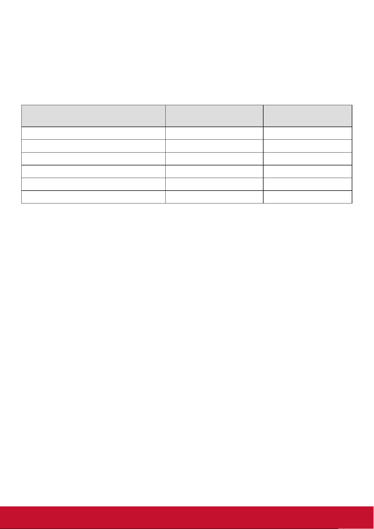
Declaration of RoHS2 Compliance
This product has been designed and manufactured in compliance with Directive 2011/65/EU of the
European Parliament and the Council on restriction of the use of certain hazardous substances in
electrical and electronic equipment (RoHS2 Directive) and is deemed to comply with the maximum
concentration values issued by the European Technical Adaptation Committee (TAC) as shown
below:
Substance
Proposed Maximum
Concentration
Actual Concentration
Lead (Pb) 0,1% < 0,1%
Mercury (Hg) 0,1% < 0,1%
Cadmium (Cd) 0,01% < 0,01%
Hexavalent Chromium (Cr
6+
) 0,1% < 0,1%
Polybrominated biphenyls (PBB) 0,1% < 0,1%
Polybrominated diphenyl ethers (PBDE) 0,1% < 0,1%
Certain components of products as stated above are exempted under the Annex III of the RoHS2
Directives as noted below:
Examples of exempted components are:
1. Mercury in cold cathode uorescent lamps and external electrode uorescent lamps (CCFL and
EEFL) for special purposes not exceeding (per lamp):
(1) Short length (≦500 mm): maximum 3.5 mg per lamp.
(2) Medium length (>500 mm and ≦1,500 mm): maximum 5 mg per lamp.
(3) Long length (>1,500 mm): maximum 13 mg per lamp.
2. Lead in glass of cathode ray tubes.
3. Lead in glass of uorescent tubes not exceeding 0.2% by weight.
4. Lead as an alloying element in aluminium containing up to 0.4% lead by weight.
5. Copper alloy containing up to 4% lead by weight.
6. Lead in high melting temperature type solders (i.e. lead-based alloys containing 85% by weight
or more lead).
7. Electrical and electronic components containing lead in a glass or ceramic other than dielectric
ceramic in capacitors, e.g. piezoelectronic devices, or in a glass or ceramic matrix compound.
ii
Page 5

Safety Precautions
FOR OPTIMUM PERFORMANCE, PLEASE NOTE THE FOLLOWING WHEN SETTING UP AND
USING THE LCD COLOR MONITOR:
• DO NOT REMOVE MONITOR BACK COVER. There are no user serviceable parts inside and
opening or removing covers may expose you to dangerous shock hazards or other risks. Refer
all servicing to qualied service personnel.
• Do not spill any liquids into the cabinet or use your monitor near water.
• Do not insert objects of any kind into the cabinet slots, as they may touch dangerous voltage
points, which can be harmful or fatal or may cause electric shock, re or equipment failure.
• Do not place any heavy objects on the power cord. Damage to the cord may cause shock or
re.
• Do not place this product on a sloping or unstable cart, stand or table, as the monitor may fall,
causing serious damage to the monitor.
• Do not place any objects onto the monitor and do not use the monitor outdoors.
• The inside of the uorescent tube located within the LCD monitor contains mercury. Please
follow the laws or rules of your municipality to dispose of the tube properly.
• Do not bend power cord.
• Do not use monitor in high temperature, humid, dusty, or oily areas.
• If monitor or glass is broken, do not come in contact with the liquid crystal and handle with
care.
• Allow adequate ventilation around the monitor, so that heat can properly dissipate. Do not
block ventilated openings or place the monitor near a radiator or other heat sources. Do not
put anything on top of the monitor.
• The power cable connector is the primary means of detaching the system from the power
supply. The monitor should be installed close to a power outlet, which is easily accessible.
• Handle with care when transporting. Save packaging for transporting.
• Please clean the holes of back cabinet to reject dirt and dust at least once a year because of
set reliability.
• If using the cooling fan continuously, it’s recommended to wipe holes a minimum of once a
month.
• When installing the remote control batteries;
- Align the batteries according to the (+) and (-) indications inside the case.
- Align the (-) indication of the battery rst inside the case.
• Usage of other than specied head- or earphones can result in hearing loss due to excessive
sound pressures.
iii
Page 6

CAUTION:
Immediately unplug your monitor from the wall outlet and refer servicing to qualified service
personnel under the following conditions:
• When the power supply cord or plug is damaged.
• If liquid has been spilled, or objects have fallen into the monitor.
• If the monitor has been exposed to rain or water.
• If the monitor has been dropped or the cabinet damaged.
• If the monitor does not operate normally by following operating instructions.
Recommended Use
CAUTION:
• For optimum performance, allow 20 minutes for warm-up.
• Rest your eyes periodically by focusing on an object at least 5 feet away. Blink often.
• Position the monitor at a 90° angle to windows and other light sources to minimize glare and
reections.
• Clean the LCD monitor surface with a lint-free, nonabrasive cloth. Avoid using any cleaning
solution or glass cleaner!
• Adjust the monitor’s brightness, contrast and sharpness controls to enhance readability.
• Avoid displaying xed patterns on the monitor for long periods of time to avoid image
persistence (after image effects).
• Get regular eye checkups.
Ergonomics
To realize the maximum ergonomic benefits, we recommend the following:
• Use the preset Size and Position controls with standard signals.
• Use the preset Color Setting.
• Use non-interlaced signals.
• Do not use primary color blue on a dark background, as it is difcult to see and may produce
eye fatigue due to insufcient contrast.
iv
Page 7

Table Of Contents
1. Unpacking and Installation .................. 1
1.1. Unpacking ...................................... 1
1.2. Package Contents .......................... 1
1.3. Installation Notes ............................ 1
1.4. Installing and Removing Table
Stands (optional) ............................ 2
1.5. Mounting on a Wall ......................... 3
1.6. Mounting in Portrait Position .......... 4
1.7. Using of Remote sensor and power
indicator ......................................... 4
2. Parts and Functions ............................. 5
2.1. Control Panel ................................. 5
2.2. Input/Output Terminals ................... 6
2.3. Remote Control .............................. 7
2.3.1. General functions ................. 7
2.3.2. Inserting batteries in the
remote control ...................... 8
2.3.3. Handling the remote control . 8
2.3.4. Operating range of the remote
control .................................. 8
3. Connecting External Equipment ......... 9
3.1. Connecting External Equipment
(DVD/VCR/VCD) ............................ 9
3.1.1. Using HDMI video input ....... 9
3.2. Connecting a PC ............................ 9
3.2.1. Using VGA input ................... 9
3.2.2. Using DVI input .................. 10
3.2.3. Using HDMI input ............... 10
3.2.4. Using DisplayPort input .......11
3.3. Connecting Audio Equipment ........ 11
3.3.1. Connecting an external audio
device ..................................11
3.4. Connecting Multiple Displays in a
Daisy-chain Conguration ............ 12
3.4.1. Display control connection . 12
3.4.2. Digital video connection ..... 12
3.5. IR connection .............................. 13
3.6. IR Pass-through Connection ....... 13
4. Operation ............................................. 14
4.1. Watch the Connected Video
Source .......................................... 14
4.2. Change Picture Format ................ 14
4.3. Media Player ................................ 14
4.3.1. Base settings in Display ..... 14
4.3.2. Signage Manager ............... 14
4.4. Web Browser ................................ 16
4.5. PDF Reader ................................. 17
4.6. Custom ......................................... 18
4.7. Setting (Admin mode) .................. 19
4.7.1. Wi-Fi ................................... 19
4.7.2. Ethernet ............................. 19
4.7.3. Signage Display ................. 20
4.7.4. System Tools ...................... 20
4.7.5. Storage .............................. 20
4.7.6. Apps ................................... 20
4.7.7. Date & Time ....................... 20
4.7.8. Development Setting .......... 21
4.7.9. About .................................. 21
5. OSD Menu ............................................ 21
5.1. Settings ........................................ 22
5.1.1. Picture menu ...................... 22
5.1.2. Screen menu ...................... 22
5.1.3. Audio menu ........................ 23
5.1.4. PIP menu ........................... 24
5.1.5. Cong1 menu ..................... 24
5.1.6. Cong2 menu ..................... 25
5.1.7. Advanced menu ................. 26
6. USB device compatibility ................... 31
7. Input mode .......................................... 32
8. Cleaning and Troubleshooting .......... 33
8.1. Cleaning ....................................... 33
8.2. Troubleshooting ............................ 34
9. TechnicalSpecications .................... 35
9.1. CDM4300R .................................. 35
9.2. CDM4900R .................................. 37
9.3. CDM5500R .................................. 39
10. RS232 Protocol ................................... 41
10.1. Introduction .................................. 41
10.2. Description ................................... 41
10.2.1. Hardware specication ..... 41
10.2.2. Communication Setting .... 41
10.2.3. Command Message
Reference .......................... 41
10.3. Protocol ........................................ 42
10.3.1. Set-Function Listing .......... 42
10.3.2. Get-Function Listing ......... 45
10.3.3. Remote Control Pass-
through mode ..................... 48
11. Other Information ............................... 51
Customer Support................................. 51
Limited Warranty .................................. 52
Mexico Limited Warranty ...................... 54
v
Page 8

Copyright Information
Copyright © ViewSonic® Corporation, 2016. All rights reserved.
ViewSonic
ViewSonic Corporation.
ENERGY STAR
As an ENERGY STAR® partner, ViewSonic Corporation has determined that this product meetsthe
ENERGY STAR® guidelines for energy efficiency.
Disclaimer: ViewSonic Corporation shall not be liable for technical or editorial errors or omissions
contained herein; nor for incidental or consequential damages resulting from furnishing this
material, or the performance or use of this product.
In the interest of continuing product improvement, ViewSonic Corporation reserves the right to
change product specifications without notice. Information in this document may change without
notice.
No part of this document may be copied, reproduced, or transmitted by any means, for any purpose
without prior written permission from ViewSonic Corporation.
©
, the three birds logo, OnView, ViewMatch, and ViewMeter are registered trademarks of
®
is a registered trademark of the U.S. Environmental Protection Agency (EPA).
Product Registration
To meet your future needs, and to receive any additional product information as it becomes
available, please register your product on the Internet at:
www.viewsonic.com.
The ViewSonic
which you may mail or fax to ViewSonic.
®
Wizard CD-ROM also provides an opportunity for you to print the registration form,
For Your Records
Product Name:
Model Number:
Document Number:
Serial Number:
Purchase Date:
Product disposal at end of product life
ViewSonic respects the environment and is committed to working and living green. Thank you for
being part of Smarter, Greener Computing.
CDM4300R/CDM4900R/CDM5500R
ViewSonic Commercial Display
VS16466/VS16467/VS16468
CDM4300R/CDM4900R/CDM5500R_UG_ENG Rev. 1A 02-24-17
Please visit ViewSonic website to learn more.
USA & Canada: http://www.viewsonic.com/company/green/recycle-program/
Europe: http://www.viewsoniceurope.com/uk/support/recycling-information/
Taiwan: http://recycle.epa.gov.tw/recycle/index2.aspx
vi
Page 9
1. Unpacking and Installation
1.1. Unpacking
• This product is packed in a carton, together with the standard accessories.
• Any other optional accessories will be packed separately.
• Due to the size and weight of this display it is recommended for two people to move it.
• After opening the carton, ensure that the contents are complete and in good condition.
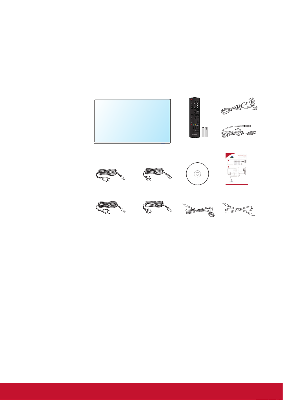
1.2. Package Contents
Please verify that you received the following items with your package content:
• LCD display
• CD ROM
• Remote control with AAA
batteries
• Quick Start Guide
• Power cord (1.8 m)
• RS232 cable (1.8 m)
• RS232 daisy chain cable
(2.4mm-2.4mm)
• IR sensor cable
• DVI to VGA cable
• USB cable (Type A-B)
* The supplied power cord varies depending on destination.
For EU For China
Remote Control
and AAA Batteries
CD ROM
DVI to VGA cable
USB cable (Type A-B)
Quick Start Guide
For North America For UK
RS232 Cable RS232 daisy chain cable
NOTES:
• For all other regions, apply a power cord that conforms to the AC voltage of the power socket and has
been approved by and complies with the safety regulations of the particular country.
• Keep the package box and packing material for shipping the display.
1.3. Installation Notes
• Due to the high power consumption, always use the plug exclusively designed for this product. If an
extended line is required, please consult your service agent.
• The product should be installed on a at surface to avoid tipping. The distance between the back of
the product and the wall should be maintained for proper ventilation. Avoid installing the product in the
kitchen, bathroom or any other places with high humidity so as not to shorten the service life of the
electronic components.
• The product can normally operate only under 2000 m in altitude. In installations at altitudes above 2000 m,
some abnormalities may be experienced.
1
Page 10
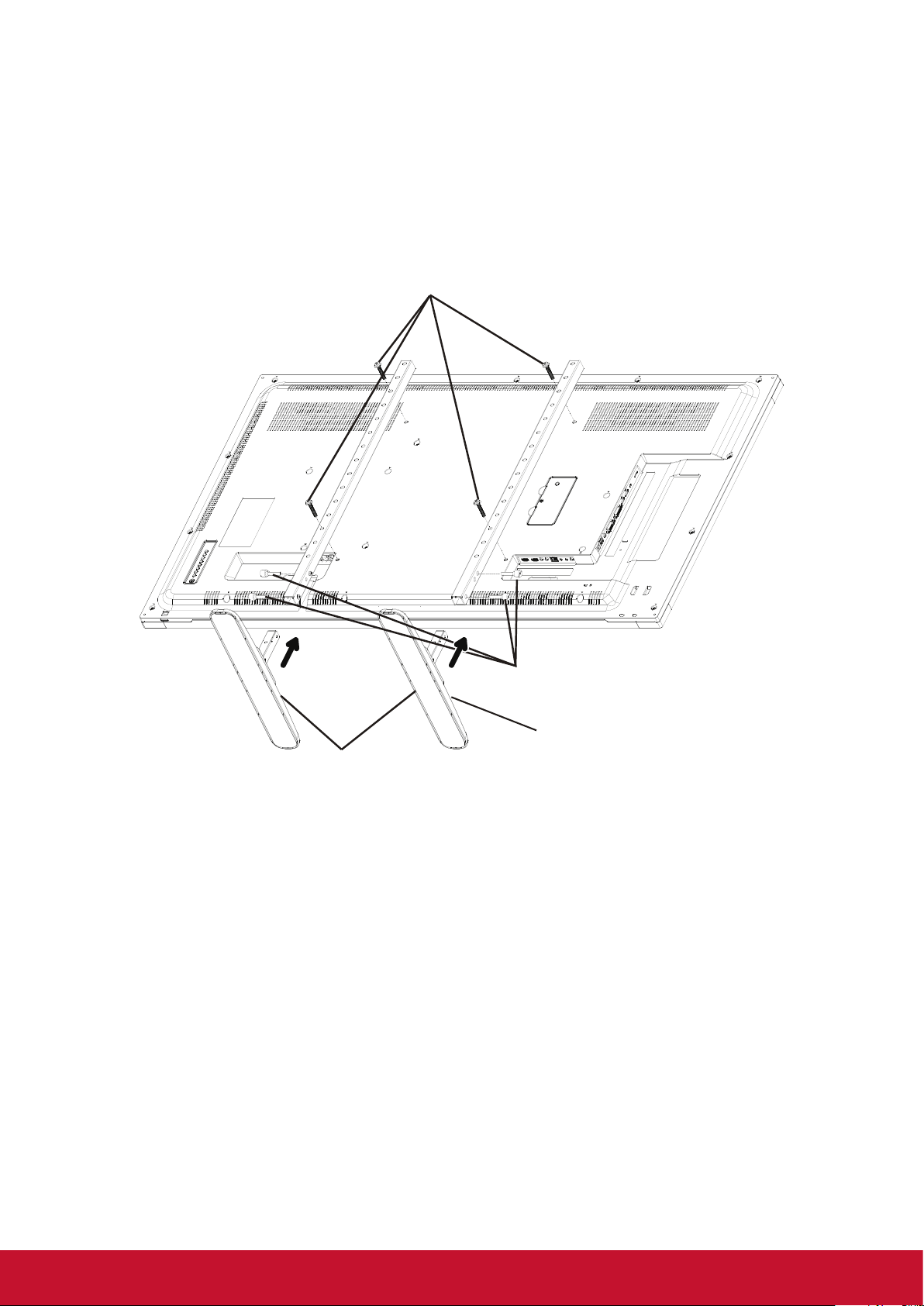
1.4. Installing and Removing Table Stands (optional)
Step 1- Put on the table
Lay a protective sheet on the table, whick was wrapped arround the display when it was packaged, beneach
the screen surface so as not to scratch the screen face.
Step 2- Fix the tube to the display (by using M6xL41 screws)
Please refer to the following drawing to know the position of screws.
Step 3- Set up the stand (by using thumb)
M6xL41 screws
Thumbscrews
Longer portions face the front
Table stand
To remove table stands:
1. Power off the display.
2. Spread a protective sheet on a at surface.
3. Place the display face-down on the protective sheet.
4. Remove screws using a screwdriver and place them in a safe place for reuse.
2
Page 11
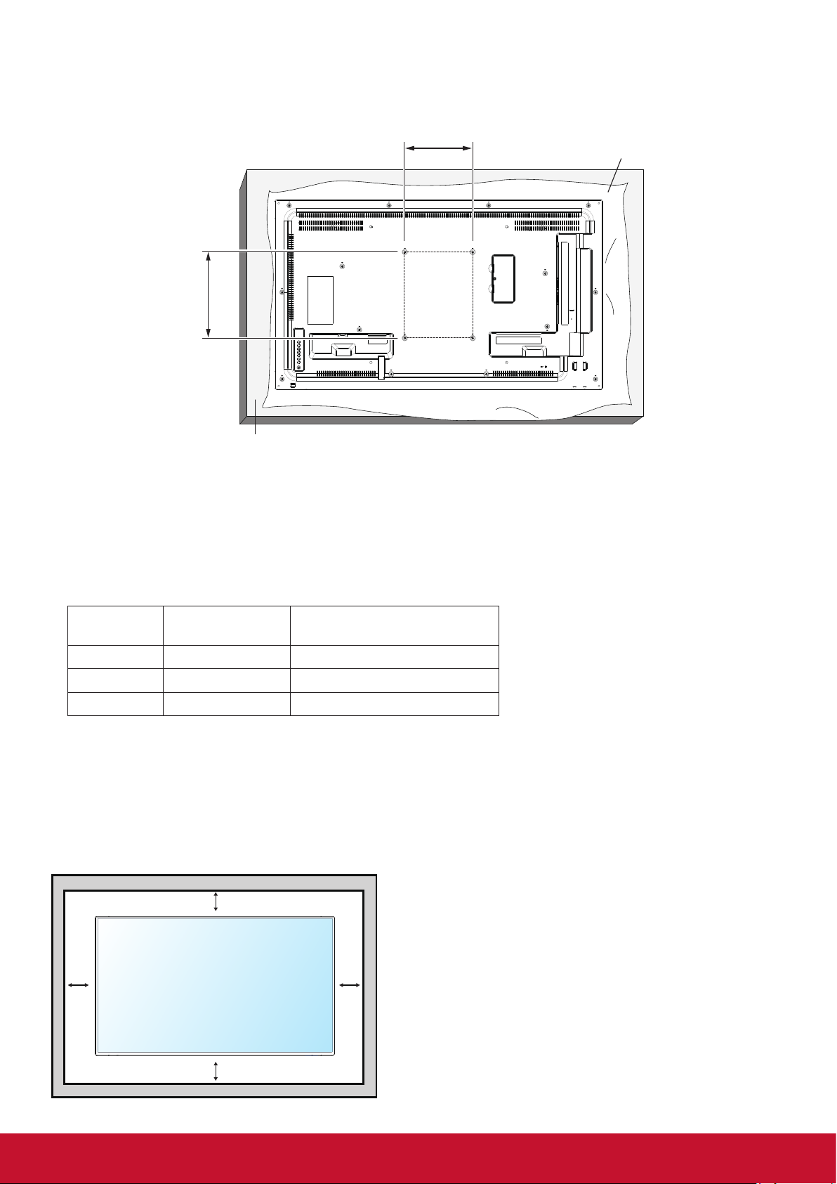
1.5. Mounting on a Wall
To mount this display to a wall, you will have to obtain a standard wall-mounting kit. We recommend using a
mounting interface that complies with UL1678 standard in North America.
400
400
Table
Protective Sheet
1. Lay a protective sheet on a table, which was wrapped around the display when it was packaged, beneath
the screen surface so as not to scratch the screen face.
2. Ensure you have all accessories for mounting this display.
3. Follow the instructions that come with the base mounting kit. Failure to follow correct mounting
procedures could result in damage to the equipment or injury to the user or installer. Product warranty
does not cover damage caused by improper installation.
4. For the wall-mounting kit, use mounting screws and tighten them securely:
Model VESA Size (mm)
Mounting Screws
(X=Thickness of wall-mount plate)
CDM4300R 400 × 400 M6 × (10 + X)
CDM4900R 400 × 400 M6 × (10 + X)
CDM5500R 400 × 400 M6 × (10 + X)
Caution:
To prevent the display from falling:
• To lessen the probability of injury and damage resulting from fall of the display in case of earthquake or
other natural disaster, be sure to consult the bracket manufacturer for installation location.
Enclosure Ventilation Requirements
To allow heat to disperse, leave space between surrounding objects as shown in the diagram below.
100 mm
100 mm 100 mm
NOTE: When installing the display on a wall,
100 mm
please consult a professional technician for
proper installation. We accept no liability for
installations not performed by a professional
technician.
3
Page 12
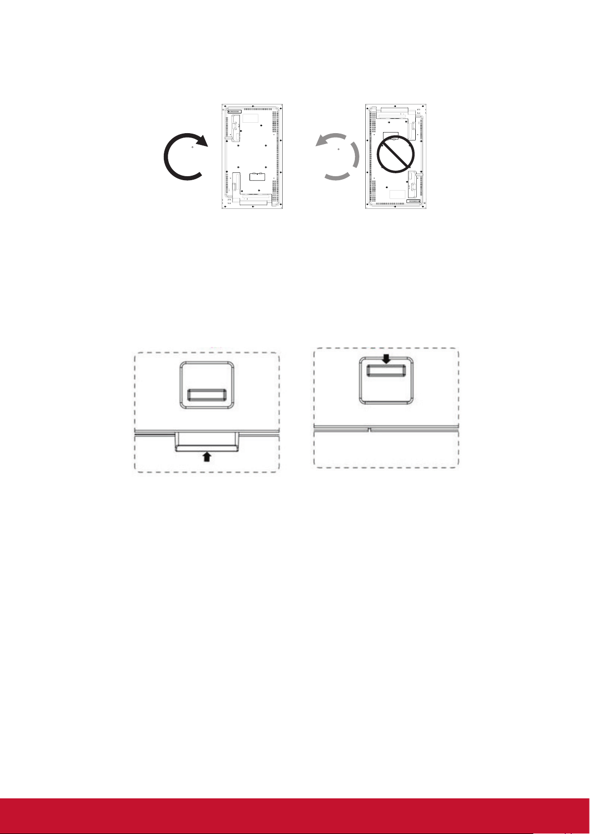
1.6. Mounting in Portrait Position
This display can be installed in portrait position.
1. Remove the table stand, if attached.
2. Rotate 90 degrees clockwise.
90
90
1.7. Using of Remote sensor and power indicator
1. Push down the lens to have better remote control performance and easy to observe the light information
of power status..
2. Push up the lens before mounting the display for video wall application.
3. Pull/Push the lens until hearing the click sound.
Push up to collapse the lens Push down to extend the lens
4
Page 13
2. Parts and Functions
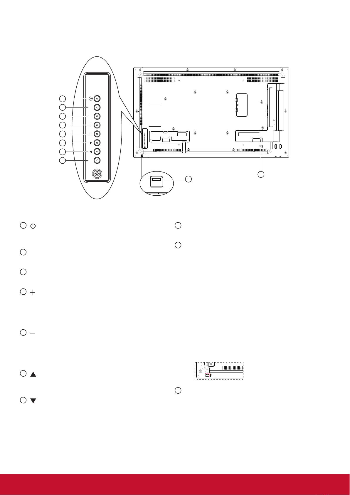
2.1. Control Panel
1
[ ] button
1
2
3
4
5
6
7
8
MUTE INPUT
MENU
Use this button to turn the display on or put the
display to standby.
2
[MUTE] button
Switch the audio mute ON/OFF.
3
[INPUT] button
Press to select input source.
4
[ ] button
Press to move the highlight bar right to selected item
or increase the adjustment while OSD menu is on, or
to increase the audio output level while OSD menu is
off.
5
[ ] button
Press to move the highlight bar left to selected item
or decrease the adjustment while OSD menu is on,
or to decrease the audio output level while OSD
menu is off.
9
8
[[MENU] button
10
Press to access the OSD menu.
9
Remote control sensor and power status
indicator
• Receives command signals from the remote
control.
• Indicates the operating status of the display:
- Lights green when this display is turned on
- Lights red when this display is in standby mode
or DC power off.
- Lights amber when the display enters Sleeping
mode.
- When {SCHEDULE} is enabled, the light blinks green
and red.
- Lights off when the main power of the display is
turned off or {Power LED light} turn off.
• Push up to hide the lens:
6
[ ] button
Press to move the highlight bar up while OSd menu
is on.
7
[ ] button
Press to move the highlight bar down while OSD
menu is on.
10
SECURITY LOCK
Used for security and theft prevention.
5
Page 14
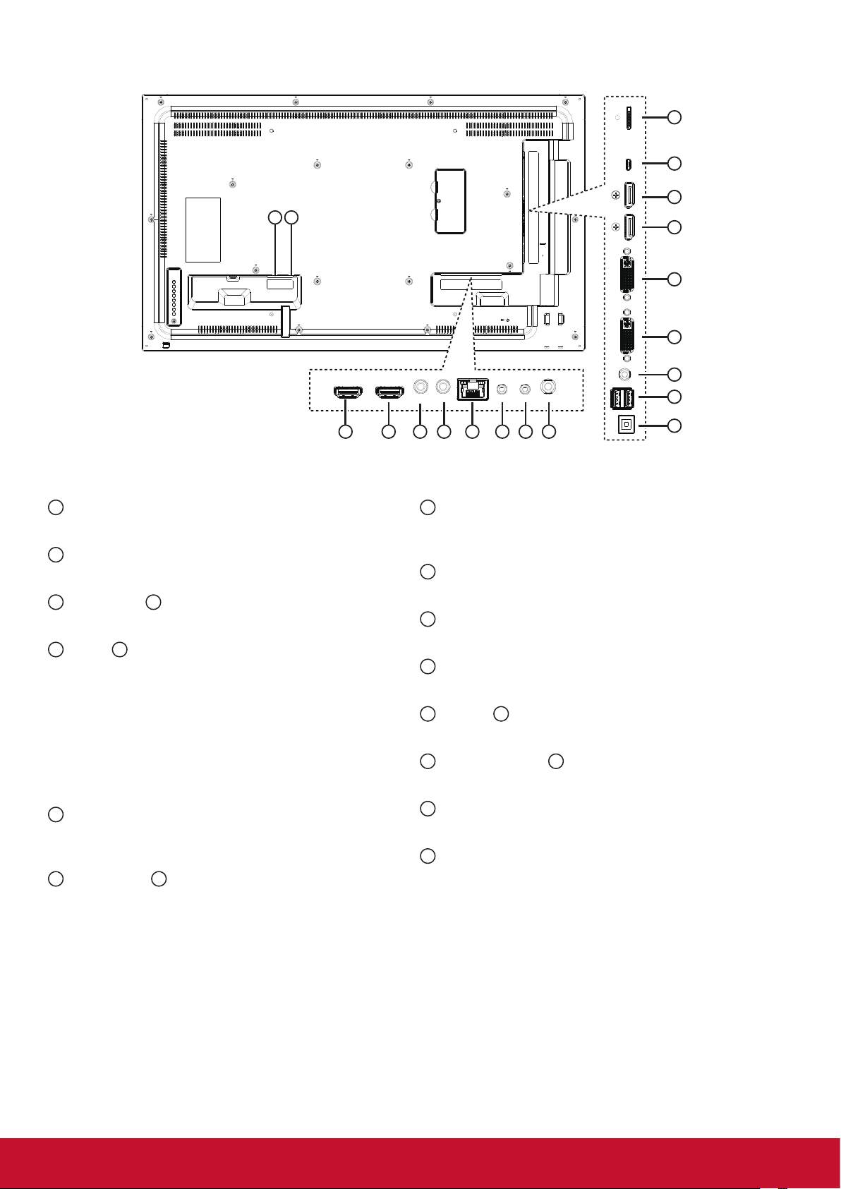
2.2. Input/Output Terminals
2 1
19
18
17
16
15
14
13
12
3 4
1
AC IN
AC power input.
2
MAIN POWER SWITCH
Main power on/off switch.
3
HDMI 1 IN / 4 HDMI 2 IN
HDMI video/audio input.
5
IR IN / 6 IR OUT (3.5 mm)
IR signal output/input for the loop-through function.
NOTES:
• This display’s remote control sensor will stop
working if the jack [IR IN] is connected.
• To remotely control your A/V device via this
display, refer to page 13 for IR Pass Through
connection.
7
RJ-45
LAN control function for the use of remote control
signal from control center.
8
RS232C IN / 9 RS232C OUT (2.5 mm)
RS232C network output/input for the loop-through
function.
6 7 8 10
5
10
AUDIO OUT (3.5mm)
9
11
Audio signal output to connect your external AV
device.
11
USB-B
Service port.
12
USB PORT/USB power supply (5V2A)
Connect your USB storage device.
13
LINE IN (3.5mm)
Audio input from your PC.
14
DVI IN / 15 DVI OUT
DVI-D video input.
16
DisplayPort IN / 17 DisplayPort OUT
DisplayPor t video input / output.
18
MICRO USB
Micro USB support OTG and Firmware update.
19
MICRO SD
Micro SD card support 32GB (Max.)
6
Page 15
2.3. Remote Control
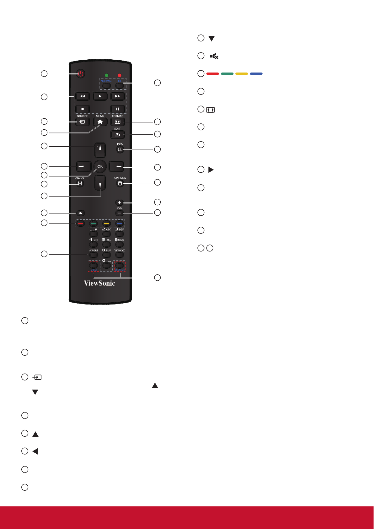
2.3.1. General functions
1
2
3
4
5
6
7
8
9
10
11
12
20
13
14
15
16
17
18
19
NOTE: This button is functional for VGA input only.
9
[ ] button
Press to move the se
10
[ ] MUTE button
tion down in OSD menu.
lec
Press to turn the mute function on/off.
11
COLOR buttons
Choose tasks or options.(for Media Input only).
12
[NUMERIC] buttons
Enter text for network setting.
13
Format button
Press to switch screen aspect ratio.
14
[EXIT] button
Press to turn back to the previous OSD menu.
15
[INFO] button
Press to turn on/off the information OSD displayed
on the upper right corner of the screen.
16
[ ] button
Press to increase the value in OSD menu.
17
[OPTION] button
Access currently available options, picture and
sound menus (for Media Input only).
18
[+] Volume up button
Press to increase the audio output level.
19
[-] Volume down button
Press to decrease the audio output level.
20 21
[ID SET] button
If a single large- screen matrix (video wall) is
created, set ID key to control each dispaly.
21
1
[POWER] button
Press to switch on the display from standby mode.
Press again to turn it off and back into standby
mode.
2
[PLAY] button
Control playback of media les (for Media Input
only).
3
[ SOURCE] button
Press to toggle Video Source Menu. Press [
] or
[ ] button to select one of the video sources among
Displayport, DVI-D, VGA, HDMI1, HDMI2, Media
Player, Browser or PDF Player. Press [OK] button.
4
[MENU] button
Press to turn the OSD menu on/off.
5
[ ] button
Press to move the selection up in OSD menu.
6
[ ] button
Press to decrease the value in OSD menu.
7
[OK] button
Press to activate the setting inside the OSD menu.
8
[ADJUST] button
Press to run the Auto Adjust function.
ID Remote Control:
You can set the remote control ID when you want to use
this remote control on one of several different displays.
Press [ID] button. The red LED blinks twice.
1. Press [ID SET] button for more than 1 second to
enter the ID ode. The red LED lights up.
Press the [ID SET] button again will exit the ID
Mode. The red LED lights off.
Press the digit number [0] ~ [9] to select the display
you want to control.
For example: press [0] and [1] for display No.1,
press [1] and [1] for display No. 11.
The numbers available are from [01] ~[255].
2. Not pressing any button within 10 seconds will exit
the ID Mode.
3. If an error pressing of buttons other than the digits
occurred, wait 1 second after the red LED lights
off and then lights up again, then press the correct
digits again.
4. Press [ID ENTER] button to conrm. The red LED
blinks twice and then lights off.
NOTE:
• Press [NORMAL] button. The green LED blinks
twice, indicating the display is in normal operation.
It is ncecssary to set up the ID number for each
display before selecting its ID number.
7
Page 16
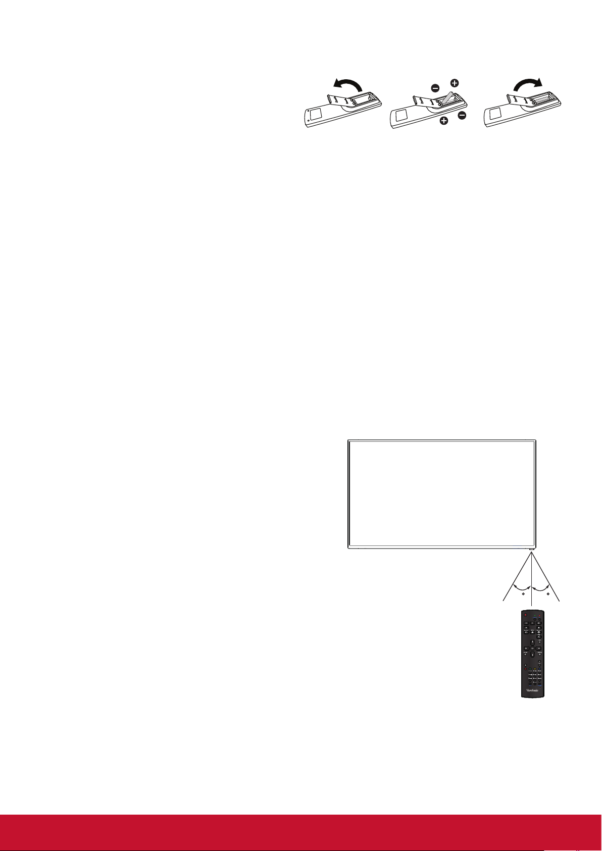
2.3.2. Inserting batteries in the remote control
The remote control is powered by two 1.5V AAA batteries.
To install or replace batteries:
1. Press and then slide the cover to open it.
2. Align the batteries according to the (+) and (–)
indications inside the battery compartment.
3. Replace the cover.
Caution:
The incorrect use of batteries can result in leaks or bursting. Be sure to follow these instructions:
• Place “AAA” batteries matching the (+) and (–) signs on each battery to the (+) and (–) signs of the
battery compartment.
• Do not mix battery types.
• Do not combine new batteries with used ones. It causes shorter life or leakage of batteries.
• Remove the dead batteries immediately to prevent them from liquid leaking in the battery compartment.
Don’t touch exposed battery acid, as it can damage your skin.
NOTE: If you do not intend to use the remote control for a long period, remove the batteries.
2.3.3. Handling the remote control
• Do not subject to strong shock.
• Do not allow water or other liquid to splash the remote control. If the remote control gets wet, wipe it dry
immediately.
• Avoid exposure to heat and steam.
• Other than to install the batteries, do not open the remote control.
2.3.4. Operating range of the remote control
Point the front of the remote control toward this display’s
remote control sensor when pressing a button.
Use the remote control within a distance of less than 10m/33ft
from this display’s sensor, and a horizontal and vertical angle
of less than 30 degrees.
NOTE: The remote control may not function properly when
the remote control sensor on this display is under
direct sunlight or strong illumination, or when there is
an obstacle in the path of signal transmission.
30 30
8
Page 17
3. Connecting External Equipment
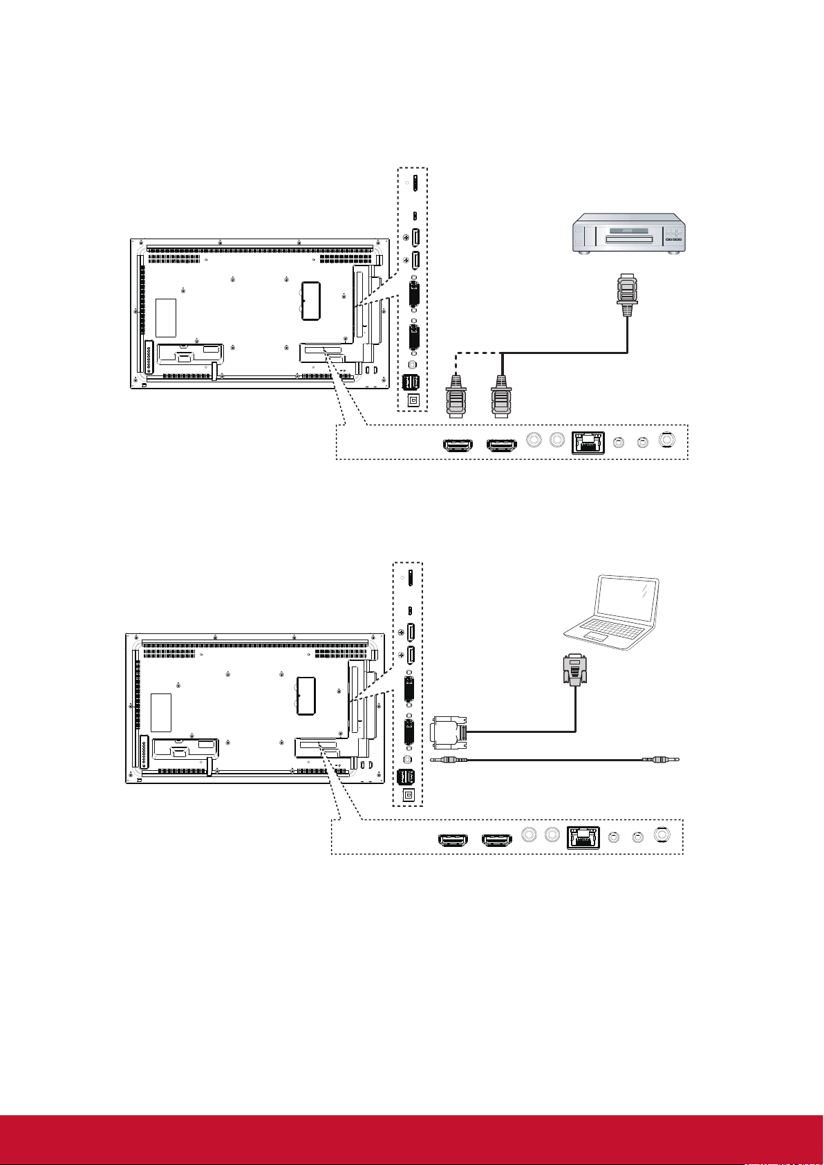
3.1. Connecting External Equipment (DVD/VCR/VCD)
3.1.1. Using HDMI video input
DVD / VCR / VCD
HDMI OUT
[HDMI IN]
3.2. Connecting a PC
3.2.1. Using VGA input
PC
VGA OUT
D-Sub 15 pin
[DVI IN]
AUDIO OUT
[VGA AUDIO IN]
9
Page 18
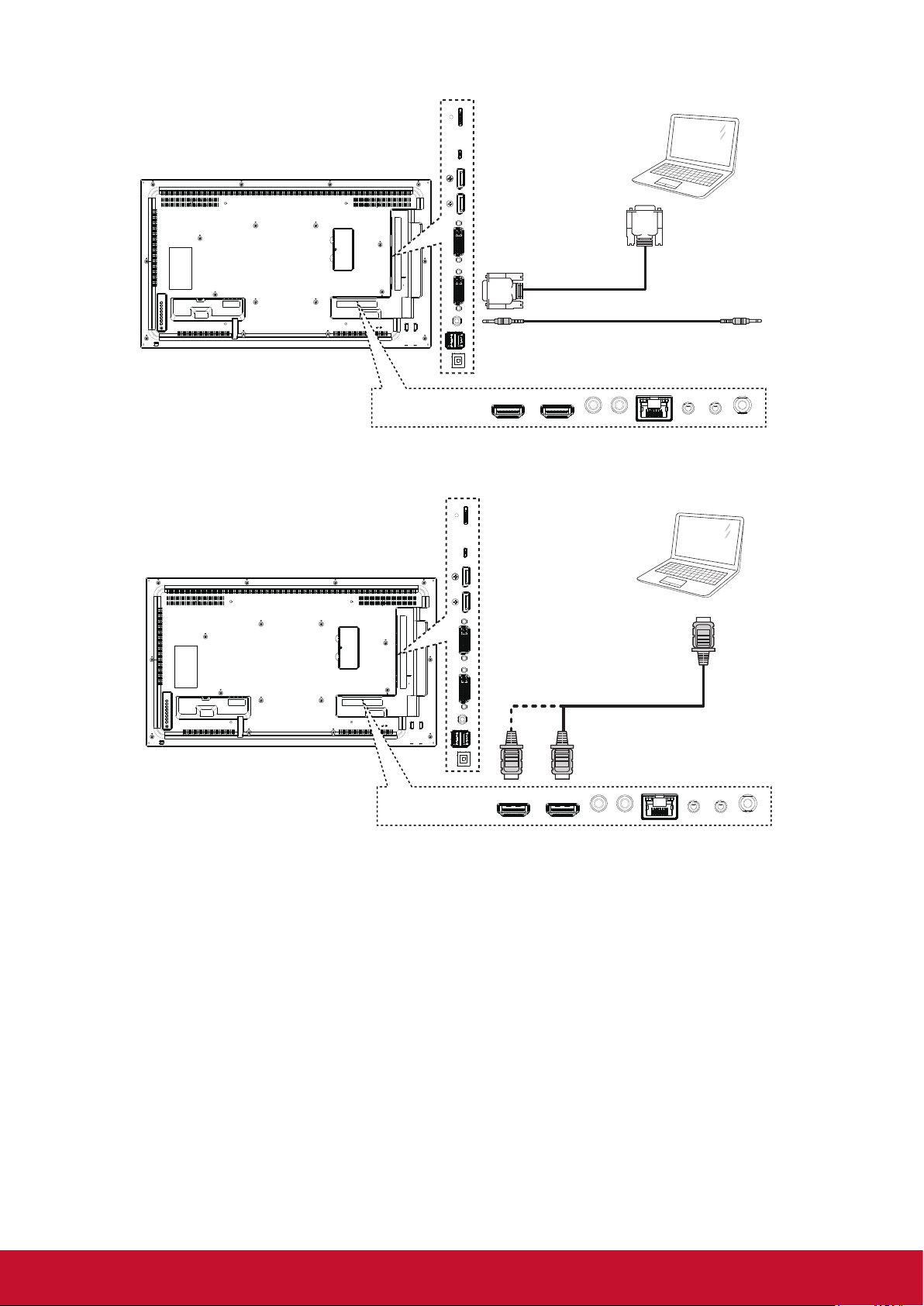
3.2.2. Using DVI input
3.2.3. Using HDMI input
PC
DVI OUT
[DVI IN]
AUDIO OUT
[VGA AUDIO IN]
PC
HDMI OUT
[HDMI IN]
10
Page 19
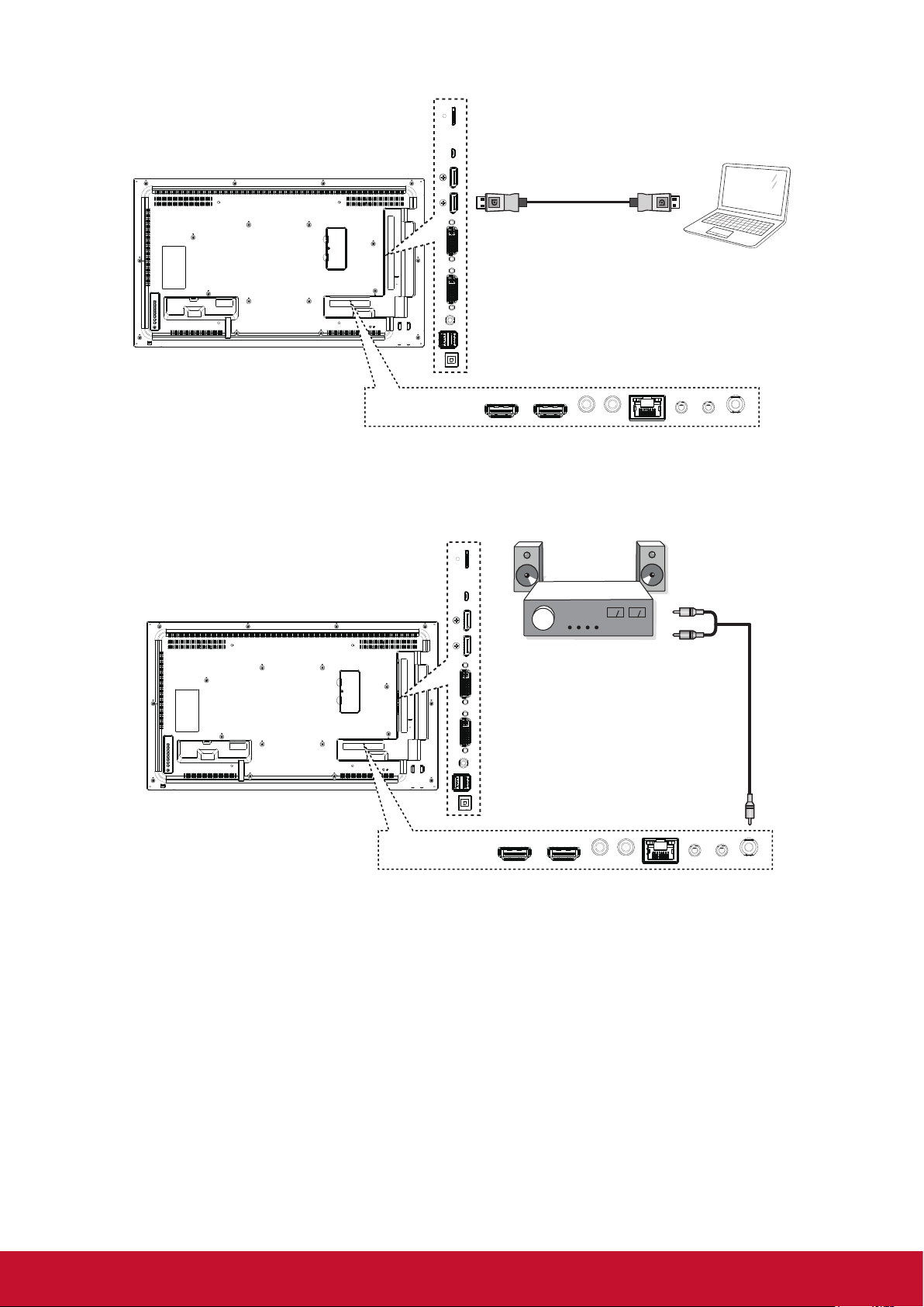
3.2.4. Using DisplayPort input
3.3. Connecting Audio Equipment
3.3.1. Connecting an external audio device
[DisplayPort IN]
PC
DisplayPort OUT
AUDIO IN
STEREO AMPLIFIER
AUDIO OUT
11
Page 20

3.4. Connecting Multiple Displays in a Daisy-chain Configuration
You can interconnect multiple displays to create a daisy-chain conguration for applications such as a video
wall.
3.4.1. Display control connection
Connect the [RS232C OUT] connector of DISPLAY 1 to the [RS232C IN] connector of DISPLAY 2.
DISPLAY 1
[RS-232C]
PC
[RS-232C IN] [RS-232C OUT] [RS-232C IN]
DISPLAY 2
3.4.2. Digital video connection
Connect the [DVI OUT] connector of DISPLAY 1 to the [DVI IN] connector of DISPLAY 2.
DISPLAY 1 DISPLAY 2
PC
[DVI]
[DVI IN] [DVI IN][DVI OUT]
Connect the [DP OUT] connector of DISPLAY 1 to the [DP IN] connector of DISPLAY 2.
DISPLAY 1 DISPLAY 2
PC
[DP]
[DP IN] [DP IN][DP OUT]
12
Page 21

3.5. IR connection
External
IR Receiver
[IR IN]
DISPLAY 1
[IR OUT] [IR IN] [IR OUT]
DISPLAY 2
NOTE: This display’s remote control sensor will stop working if the [IR IN] is connected.
3.6. IR Pass-through Connection
[IR OUT]
DISPLAY
DVD / VCR / VCD
(DVD / VCR / VCD)
Remote Control
[IR IN]
13
Page 22

4. Operation
NOTE: The control button described in this section
is mainly on the remote control unless
specied otherwise.
4.1. Watch the Connected Video Source
See page 8 for external equipments
connection.
1. Press
2. Press
press OK button.
SOURCE button .
or button to select a device, then
4.3. Media Player
You can publish videos, photos, music and widget
to play from Signage Manager Software.
4.3.1. Base settings in Display
Ethernet: To turn Ethernet On or Off.
Wireless LAN : To turn Wireless LAN On or Off.
Time Zone: User can set up Time Zone manually.
4.3.2. Signage Manager
You can create content playlist from Signage
Manager and publish to display.
4.2. Change Picture Format
You can change the picture format to suit the video
source. Each video source has its available picture
formats.
The available picture formats depend on the video
source:
Press
format.
• {FULL}: Enlarge the picture to ll the screen.
• {NORMAL}: 4:3 format.
• {DYNAMIC}: 16:9 format.
• {REAL}: This mode displays the image
• {21:9}: 21:9 format.
• {CUSTOM}: Custom dene.
FORMAT button to change the picture
pixel-by-pixel on screen without scaling the
original image size.
NOTE: Please download Signage Manager from
http://vsweb.us/signagemanager and install
on your PC.
1. Press {Create playlist} button
2. Select player model
14
Page 23

3. Select Orientation, Empty templates and Predesigned templates and press
to next step.
6. And then you can export to player or USB
• Export to Player (Display)
4. Press {Edit schedule} button to add schedule
5. Press {Add schedule} button to set playlist
schedule
• Select player and press OK
• It will show player status.
• Export to USB
15
Page 24

4.4. Web Browser
You can save the web link and easy to browse the
web site.
Browser page has one item: {Settings}. Press
{Settings} then enter next page.
2. Press “Option” then left side will pop up a list
Import : Import url list le
Export : Export url list le
Delete all : Delete all url record on right side
Back : left side list will be close.
1. Users can choose 1~7. Press any one will show
a dialog.
Enter URL and press OK then data will save on
List
A. Import
Click Import, you can select URL le from Internal,
USB storage or SD card.
After URL le selected, URL will show on list.
16
Page 25

B. Export
Click Export, you can select Internal, USB storage
or SD card for export le to.
Dialog shows path le will be saved and le’s
name. Press “save” button then URLs on list will
be saved.
4.5. PDF Reader
You can play PDF le on your display from
internal, USB or SD card.
This page has three items: {Play}, {Compose}
and {Settings}.
• {Play} : select playlist to play.
• {Compose}: edit playlist.
• {Settings}: setting play properties.
1. Select {Play} on this page, rst you should choose one
playlist to play between FILE 1 and FILE 7. The pencil
icon means the playlist is non-empty.
3. On URL list page, if you select non-empty item,
it will show a dialog to ask edit or play url. If
press “Edit”, it will show edit url dialog, if press
“Play”, it will show web page of item’s url.
2. Select {Compose} on this page, rst you
should choose one playlist to edit between
FILE 1 and FILE 7. The pencil icon means the
playlist is non-empty.
17
Page 26

A. If an empty playlist is chosen, the app will guide
you to select the media source.
All media les should be placed in /viewsonic/
of root directory.
For example,
• pdfs in /root/viewsonic/pdf/
B. You could edit or delete a non-empty playlist,
just choose the desired playlist which is with
pencil icon.
Select “Sort” in the slidebar, you can change the
order of les one by one.
3. Select {Settings} on this page, this page
has two parts, {Repeat Mode} and {Effect
Duration}.
• {Repeat Mode} : play mode.
• {Effect Duration} : photo effect duration.
C. Once you start to edit a playlist, you will see
below screen.
Source - les in storage.
Playlist – les in playlist.
There are 4 icons which map to the keys of
remote controller.
Option key – launch slidebar
Play key – play media le.
Info key – show media info.
Ok key – select/unselect le.
In the slidebar, it helps you to do the following:
- select all : select all storage les.
- delete all : delete all playlist les.
- add/remove : update playlist from source.
- sort : sort playlist.
- save/abort : save or abort playlist.
- back : return.
4.6. Custom
Select custom app from source setting.
1. Entry Signage Display in Admin Mode (Refer section 4.7 &
4.7.3)
2. Select Custom app will show the installed APK.
CDM model pre-install the Enplug APK inside.
18
Page 27

3. Press Select App to show the APK list.
4.7. Setting (Admin mode)
Press Menu 1 9 9 8 on remote control to enter
admin mode.
4. Select Enplug Display and press Save.
5. Enplug Display APK name will show on Select
App.
4.7.1. Wi-Fi
Via Enable/Disable to control Wi-Fi On/Off. After
Enable, the screen will list all available WiFi AP.
Note: Ethernet will be disable automatically if WiFi
turn on and connect to network.
4.7.2. Ethernet
Enable: To turn Ethernet On.
Disable: To turn Ethernet Off
Enable Ethernet will show Connection Type and
Mac Address.
1. Connection Type: Available type is DHCP/Static IP
A. DHCP
B. Static IP
C. IP Address
D. Netmask
E. DNS Address
F. Gateway Address
2. Mack Address
Note: WiFi will be disable automatically if Etherne
turn on and connect to network.
6. Exit admin mode and press custom input
source. Enplug Display will run on screen.
19
Page 28

4.7.3. Signage Display
There are 3 groups: General Settings / Server
Settings / Source Settings.
1. General Settings
- Signage Display Name: Set the PD name,
default name is “PD” + Ethernet Mac
Address. The name is up to 36 characters.
- Boot Logo:Scalar OSD menu to control
Android boot logo enable/disable.
- Screenshot: Via Enable/Disable to control
screenshot On/Off. After Enable, user can
set screenshot timeslot and save path.
Note: Time slot of deletion and screenshot:
(1) Will delete picture at initial time 0 sec.
(2) Will screenshot at rst 40 sec.
4.7.5. Storage
Show the storage space information.
SD CARD and USB STORAGE
Need to insert SD card or USB, the information will show up
total space and available of SD card or USB storage.
2. Server Settings
- FTP: Via Enable/Disable to control FTP
On/Off.
After setup, PD can share FTP les.
3. Source Settings
- Browser: Open Browser setting page.
- PDF Reader: Open Play List and effect
setting page in PDF Player.
- Custom app: Let user select custom app.
4.7.4. System Tools
There are 3 functions:
1. Clear Storage: Clear all data in viewsonic folder.
2. Factory Reset: Reset all settings.
3. Import & Export: Import/Export PD settings.
4.7.6. Apps
Show the App information.
4.7.7. Date & Time
Via Scalar OSD menu to control Auto Time On/Off.
When Salar OSD menu turn off Auto time, user
can set up Time Zone manually.
Note: Add new NTP server to display current
serverIP.
20
Page 29

4.7.8. Development Setting
The options are for Android development.
4.7.9. About
This page will show
1. System updates
Will automatically search update.zip in USB or SD card.
Will be shown in list for user selection if found
Note:
(1) Only support Android Full image.
(2) File name should be update.zip
(3) The le should be located in root of storage.
2. Android version
3. Kernel version
4. Build number
5. OSD Menu
An overall view of the On-Screen Display (OSD)
structure is shown below. You can use it as a
reference for further adjusting your display.
Navigating the OSD menu using the remote
control:
1. Press the [
] MENU button to display the OSD
menu.
2. Press [
] [ ] [ ] or [ ] button to select its menu
item or to adjust its value. Press OK button to
conrm.
3. Press [
] EXIT button to go back to the
previous menu layer.
4. Press [
] MENU button to exit the OSD menu.
Navigating the OSD menu using the display’s
control buttons:
1. Press the MENU button to display the OSD
menu.
2. Press the [
] [ ] [ ] or [ ] to select menu item
or adjust its value.
3. Press [INPUT] button to conrm menu selection
and enter its submenu.
4. Press MENU to conrm menu selection and
enter its submenu.
21
Page 30

5.1. Settings
5.1.1. Picture menu
Picture
Screen
Audio
PIP
Configuration 1
Brightness
Contrast
Sharpness
Black level
Tint
Color
Noisereduction
Gamma selection
Color temperature
Color control
Medium
Native
Native
Brightness
Adjust the overall image and background screen
brightness.
70
50
50
50
Overscan
Change the display area of the image.
ON: Set to display area about 95%
OFF: Set to display area about 100%
Bluelightlter
User can adjust the value from 100 to 0 when the
Color temperature value > 5000º K
Flicker free
ON: Set to Backlight to Maximun and diable
Brightness adjustment
OFF: Turn off this function and set Backlight value
as brightness value.
Picture Reset
Reset all settings in the Picture menu.
5.1.2. Screen menu
Contrast
Adjust the image contrast ratio for the input signal.
Sharpness
Adjust the sharpness of the picture.
Black level
Adjust the image brightness for the background.
NOTE: sRGB picture mode is standard and cannot
be changed.
Tint
Adjust the tint of the screen.
NOTE: VIDEO mode only.
Color
Adjust the color of the screen.
NOTE: VIDEO mode only
Noise reduction
Adjust the noise reduction level.
Gamma Selection
Select a display gamma.
NOTE: sRGB picture mode is standard and cannot
be changed.
Color Temperature
adjust the color temperature.
Color Control
The color levels of red, green, and blue are
adjusted by the color bars.
R: Red gain, G: Green gain, B: Blue gain
Picture Mode
PC mode: {Standard} / {Highbright} / {sRGB}.
Video mode: {Standard} / {Highbright} /
{Cinema}.
Picture
Screen
Audio
PIP
Configuration 1
Hposition
Vposition
Clock
Clock phase
Zoom mode
Custom zoom
Auto adjust
Screen reset
21:9
Zoom
Action
Action
H Position
Control Horizontal Image position within the
display area of the LCD.
V Position
Control Vertical Image position within the display
area of the LCD.
Clock
Adjust to expand or narrow the width of the image
on the screen.
NOTE: VGA input only
Clock Phase
Improves focus, clarity and image stability by
increasing or decreasing this setting.
NOTE: VGA input only
Zoom Mode
PC mode: {Full} / {Normal} / {Real} / {Dynamic}/
{21:9}/ {Custom}.
Video mode: {Full} / {Normal} /{Real} /
{Dynamic}/ {21:9}/ {Custom}.
22
Page 31

NOTE: Zoom mode setting is by input. If input in
multi-windows, the setting will apply for windows
with the same input. And the INFO OSD will show
the latest setting.
Full
This mode restores the correct
proportions of pictures transmitted in 16:9
using the full screen display.
Normal
The picture is reproduced in 4:3 format
and a black band is displayed on either
side of the picture.
Real
This mode displays the image pixelby-pixel on screen without scaling the
original image size.
Dynamic
The picture is reproduced in 16:9 format
and a black band at the top and bottom.
21:9
The picture is reproduced in 21:9 format
and a black band at the top and bottom.
Custom
Choose to apply the custom zoom
settings in the Custom Zoom submenu.
Custom Zoom
You can use this function to further customize
the zoom settings to suit the image you want to
display.
NOTE: This item is functional only when the Zoom
mode setting is set to Custom.
Zoom
Expands the horizontal and vertical sizes
of the image simultaneously.
H zoom
Expands the horizontal size of the image
only.
V zoom
Expands the vertical size of the image
only.
H position
Moves the horizontal position of the
image left or right.
The adjustable step by Zoom and H zoom
setting.
V position
Moves the vertical position of the image
up or down.
The adjustable step by Zoom and V zoom
setting.
Auto Adjust
Press “Set” to detect and adjust H position, V
position, Clock, Phase automatically.
Screen Reset
Reset all settings in the Screen menu to factory
preset values.
5.1.3. Audio menu
Picture
Screen
Audio
PIP
Configuration 1
Balance
Treble
Bass
Volume
Audio out (line out)
Maxium volume
Minimum volume
Mute
Auto source
Sync. Volume
Off
Digital
Off
50
50
50
0
30
100
0
Balance
Adjust to emphasize left or right audio output
balance.
Treble
Adjust to increase or decrease higher-pitched
sounds.
Bass
Adjust to increase or decrease lower-pitched
sounds.
Volume
Adjust to increase or decrease the audio output
level.
Note: Minimum volume ≤ Volume ≤ Maximum
volume
Audio Out (Line Out)
Adjust to increase or decrease line out output
level.
Maximum volume
Limitation for the maximum volume setting.
Minimum volume
Limitation for the minimum volume setting.
Mute
Turn the mute function on/off.
Audio source
Select the audio input source.
Analog: audio from audio input
Digital : audio from HDMI/DVI audio.
Displyport: audio from DP.
Sync. Volume
Enable/disable audio out (line out) volume
adjustability.
Audio reset
Reset all settings in the Audio menu to factory
preset values.
23
Page 32

5.1.4. PIP menu
Picture
Screen
Audio
PIP
Configuration 1
Sub mode
PIP size
PIP position
PIP change
PIP source
PIP audio
PIP reset
Off
Small
Bottom-Right
Action
VGA
Main
Action
HDMI1 HDMI2 DVI DisplayPort VGA MediaPlayer Browser
HDMI1 O X X O O X X X X
HDMI2 X O X O O X X X X
DVI X X O O X X X X X
DisplayPort O O O O O O O O O
VGA O O X O O O O O O
Media
Player
Browser X X X O O X O X X
PDF Player X X X O O X X O X
Custom X X X O O X X X O
X X X O O O X X X
PDF
Player
(O: PIP function available, X: PIP function
unavailable)
5.1.5. Config1 menu
Custom
Sub mode
Select the PIP (Picture-in-Picture) mode.
Choose from: {Off}/{PIP}/{POP}/{Quick swap}/
{PBP}.
PIP size
Select the size of the sub picture in the PIP
(Picture-in-Picture) mode.
Choose from: {Small} / {Medium} / {Large}.
PIP position
Select the position of the sub picture in the PIP
(Picture-in-Picture) mode.
{Bottom-Right} / {Bottom-Left} / {Top-Right} /
{Top-Left}
PIP change
Exchange Main and PIP/POP/PBP/Quick swap
input signal.
PIP Source
Select the input signal for the sub picture.
PIP audio
Select the audio source in the Sub mode.
• {Main} - Select audio from the main picture
• {Sub} - Select audio from the sub picture.
PIP reset
Reset all settings in the PIP menu to factory preset
values.
NOTES
:
• The PIP function is available only for certain
signal source combinations as shown in the
table below.
• The availability of the PIP function will also
depend on the resolution of the input signal
being used.
Picture
Screen
Audio
PIP
Configuration 1
Switch on state
Panel saving
RS232 routing
Boot on source
WOL
Power LED light
Network
Configuration1 reset
Factory reset
Last status
Action
RS232
Action
Off
On
On
Action
Action
Switch on state
Select the display status used for the next time
you connect the power cord.
• {Power off} - The display will remain off
when the power cord is connected to a wall
outlet.
• {Forced on} - The display will turn on when
the power cord is connected to a wall outlet.
• {Last status} - The display will return to the
previous power status (on/off/standby) when
removing and replacing the power cord.
Panel saving
Choose to enable the panel saving functions and
thus reduce the risk of “image persistence” or
“ghost-imaging”.
• {Brightness} - Select {On} and the image
brightness will be reduced to an appropriate
level. The Brightness setting in the Picture
menu will be unavailable when selected.
• {Pixel shift} - Select the time interval ({Auto}
/ {10 ~ 900} Seconds/ {Off}) for the display
to slightly expand the image size and shift
the position of pixels in four directions (up,
down, left, or right). Activating Pixel Shift will
disable H Position, V Position and Zoom
Mode in the Screen Menu.
RS232 Routing
Select the network control port.
Choose from: {RS232} / {LAN->RS232}.
24
Page 33

Boot on Source
Choose to select source when boot up.
Input: select input source when bootup.
Playlist: select playlist index for Media player,
Browser, PDF player.
0: no play list. Same as switch source from
OSD.1~7: playlist number.
WOL
Choose to turn on or off the wake on LAN function.
Choose from : {Off} / {On}
:
NOTE
• WoL is not supported when power save
mode set as Mode 3 and Mode4.
• System only turn of backlight when DC off in
Mode 3 and Mode 4.
• If user want to power on system in Mode
3 and Mode 4, user can use power on
command of RS232 over LAN.
Power LED light
Choose to set power indicate LED on or off.
Choose {On} for normal use.
Network
Launch Network setup and the input source will be
changed to Custom for Android network setting.
When exit the network setting, input source will be
back to the latest input source.
5.1.6. Config2 menu
Configuration 2
Advanced option
OSD turn off
OSD H-position
OSD V-position
OSD transparency
Information OSD
Logo
Monitor ID
Heat status
Monitor information
DP version
Off
10 Sec
On
1
Action
Action
DP 1.1
45
50
50
OSD turn off
Set the period of time the OSD (on-screen display)
menu stays on the screen.
The options are: {0 ~ 120} seconds.
NOTE: {0} does not disappear automatically.
OSD H-position
Adjust the horizontal position of the OSD menu.
OSD V-position
Adjust the vertical position of the OSD menu.
OSD Transparency
Adjust OSD transparency.
• {Off} - Transparency off.
• {1-100} - Transparency level 1-100
LED Indicator
LED Status Power Status LED behavior
LED Active Normal ON Green
Sleeping Ambera
RC command RED blinking+GREEN
Schedule on RED+GREEN
blinking(DC Off)
If ON TIME is "--:--", the
LED is not blinking.
Standby/DC power off RED
LED Not-active Switch off Blank
Conguration1reset
Reset all settings in Conguration1 menu to the
factory preset values.
Factory reset
Reset all settings in the OSD menus of {Picture},
{Screen}, {Audio}, {PIP}, {Conguration1},
{Conguration2}, and {Advanced option} to the
factory preset values.
Android settings will also reset when factory reset.
Information OSD
Set the period of time the information OSD is
displayed on the upper right corner of the screen.
The information OSD will display when input signal
is changed.
The information OSD will remain on the screen
with {Off} selection.
The options are: {1 ~ 60} seconds.
Logo
Choose to enable or disable the picture of Logo
when turn on your display.
NOTE: Logo will NOT rotate with rotation setting/
detection.
Monitor ID
Set the ID number for controlling the display via
the RS232C connection.
Each display must have a unique ID number when
multiple sets of this display are connected. Monitor
ID number range is between 1 to 98.
Heat status
This function allows you to check the thermal
status and fan speed of the display at any time.
25
Page 34

Monitor information
Shows information about your display, including
model number, serial number, operating hours and
software version.
DP version
DisplayPort support mode.
The options are:
• {DP 1.1}: DP 1.1 single stream (clone
mode).
• {DP 1.2 SST}: DP 1.2 Single stream (clone
mode).
• {DP 1.2 MST}: DP 1.2 Multi-Stream
NOTE: The DP version must be set the same for
all daisy chain displays.
Window selection
Select the window for adjusting setting. The
selected window will be highlight green border.
Window selection will set to Main after power on.
The options are: {Main}, {PIP}
Rotation
Set the rotation of Main/Sub/OSD
Language
Select the language used in the OSD menu.
The options are: {English}/{Deutsch}/{
文
}/{Français}/{Italiano}/{Español}/{Pyccкий}/
{Polski}/{Türkçe}/{
繁體中文
}
简体中
QR Code
Display QR code of Viewsonic website for more
information.
Conguration2reset
Reset all settings in Conguration2 menu to the
factory preset values.
5.1.7. Advanced menu
Configuration 2
Advanced option
Input resolution
IR control
Keyboard control
Tiling
Off timer
Date and time
Schedule
HDMI with One Wire
Auto signal detection
Power save
Auto
Action
Action
Action
Off
Action
Action
Off
Action
Mode 1
NOTE: This item is functional for VGA input only.
The options are:
• {1024x768 / 1280x768 / 1360x768 /
1366x768}
• {1400x1050 / 1680x1050}
• {1600x1200 / 1920x1200}
• {Auto}: Determines the resolution
automatically.
The selected settings will become effective after
turning off the power and turning it on again.
IR control
Select the operation mode of the remote control
when multiple displays are connected via an
RS232C connection.
• {Normal} - All displays can be operated
normally by the remote control unit.
• {Primary} - Designate this display as the
primary display for remote control operation.
Only this display can be operated by the
remote control. (In primary mode, IR key will
always be processed regardless the monitor
id).
• {Secondary} - Designate this display as the
secondary display. This display can not be
operated by the remote control, and will only
receive the control signal from the primary
display via the RS232C connection.
• {Lock All} / {Lock all but Volume} / {Lock
all but Power}/{Lock all except PWR &
VOL} - Lock the remote control function of
this display.
NOTE: To unlock IR control, press and hold the
[Info] button on the remote control for more 6 (six)
seconds.
Keyboard control
Choose to enable or disable the display keyboard
(control buttons) function.
• {Unlock} - Enable the keyboard function.
• {Lock All} / {Lock all but Volume} / {Lock
all but Power}/{Lock all except PWR &
VOL} - Disable the keyboard function.
NOTE:
“Keyboard Control Lock Mode” This function
completely disables the access to all Keyboard
Control functions. To enable or disable the
keyboard control lock, press both [VOL+]and [UP]
buttons and hold down continuously for more than
3 (three) seconds.
Input resolution
Set the resolution of the VGA input. This is only
required when the display is unable to detect the
VGA input resolution correctly.
Tiling
With this function you can create a single largescreen matrix (video wall) that consists of up
to 225 sets of this display (up to 15-sets on the
vertical and 15-sets on the horizontal sides). This
function requires a daisy-chain connection.
26
Page 35

Tiling
Frame comp. - Yes
H monitor
V monitor
Position
Frame comp.
Enable
Switch on delay
Example: 2 x 2 screen matrix (4 displays)
H monitors = 2 displays
V monitors = 2 displays
H MONITORS
1
1
1
No
No
Off
1 2
V MONITORS
3 4
Frame comp. - No
Position
Example: 5 x 5 screen matrix (25 displays)
H monitors = 5 displays
V monitors = 5 displays
H MONITORS
1 2
6 7
3 4
8 9
5
10
11 12 13 14 15
V MONITORS
16 17 18 19 20
21 22 23 24 25
• {H monitors} - Select the number of
displays on the horizontal side.
• {V monitors} - Select the number of
displays on the vertical side.
• {Position} - Select the position of this
display in the screen matrix.
• {Frame comp.} - Choose to turn the frame
compensation function on or off. If selected
{Yes}, the display will adjust the image to
compensate for the width of the display
bezels in order to accurately display the
image.
Position
• {Enable}: Choose to enable or disable
the Tiling function. If enabled, the display
will apply the settings in {H monitors}, {V
monitors}, {Position}, and {Frame comp.}.
• {Switch on delay}: Set the power-on
delaying time (in seconds). The default
option {Auto} allows a sequential poweringon for each display by their ID number when
multiple displays are connected.
The options are:{Off/Auto/2~255}
NOTE: The Tiling function will be disabled when
the PIP enabled.
Off Timer
Set automatically power off time (in hours).
27
Page 36

Date and time
Adjust the current date and time for the display’s internal clock.
Date and time
Auto Sync
Year
Month
Day
Hour
Minute
Daylight saving time
Current data time
2016.01.01 07:15:25
Press [OK] to set clock
No
2016
1
1
1
10
1. Press [OK] button to enter the submenu.
2. Press [▲] or [▼] button to toggle between {Year}, {Month}, {Day}, {Hour}, {Minute}, and {Daylight
saving time}.
3. Press [] or [] button to adjust all settings except {Daylight saving time}.
4. Press [OK] button to enter the {Daylight saving time} submenu.
5. Press [] or [] button to select item, press [▲] or [▼] button to adjust.
NOTE: Cannot set time to date after year 2037.
Schedule
This function allows you to program up to 7 (seven) different scheduled time intervals for the display to
activate.
NOTE: We recommend you to set up current date and time in the {Date and time} menu before using this
function.
1. Press [OK] or [] button to enter the submenu.
Schedule
Today 2015.01.07 WED 22:35:22
□1
□2 On Off Input
□3 __:__ :
□4 ○MON ○TUE
□5 ○WED ○THU ○FRI
□6 ○SAT ○SUN ○Every week
□7 Playlist 0
Clear all
Press [▲] or [▼] button to select a schedule item (item number 1 ~ 7), and then press [+] button to mark it
the item number.
2. Press [] or [] button to select the schedule:
28
Page 37

Schedule
Today 2015.01.07 WED 22:35:22
□1
□2 On Off Input
□3 __:__ :
1
2 3
4
□4 ○MON ○TUE
□5 ○WED ○THU ○FRI
□6 ○SAT ○SUN ○Every week
□7 Playlist 0
5
Clear all
1
Power-on schedule: Press [▲] or [▼] button to set the hour and minute for the display to turn on.
2
Power-off schedule: Press [▲] or [▼] button to set the hour and minute for the display to turn off.
Select or leave an empty “__” for both the hour and minute slot if you do not want to use this power-on or power-off schedule.
3
Input-source selection: Press [▲] or [▼] button to select an input source. If no input source is selected, the input source will
remain the same as last selected.
4
Date schedule: Press [OK] button to select which day in a week this schedule item will be take effect, and then press the [OK]
button.
5
Playlist selection: Press [▲] or [▼] to select the playlist to be played when display power on. Playlist option is only available
when input source is android source.
3. For additional schedule settings, press [EXIT], then repeat the steps above. A check mark in the box next
to the number of the schedule item indicates that the selected schedule is in effect.
4. Clear all: Clear all sehedule settings.
NOTES:
• If the schedules overlap, the scheduled power-on time takes priority over scheduled power-off time.
• If there are two schedule items programmed for the same time, the highest numbered schedule takes
priority. For example, if schedule items #1 and #2 both set the display to power on at 7:00 AM and off
at 5:00 PM, then only schedule item # 1 will take effect.
29
Page 38

HDMI with One Wire
CEC control.
• {Off} - Disable CEC.
• {On} - Enable CEC.
Auto signal detection
Choose to let the display detect and display available signal sources automatically.
• {Off} - Once a signal is connected, it can only be selected manually.
No signal, set the display to display the image automatically according to the search order of each
option.
Power Save
Power save modes
{Mode 1}: DC off -> Power off. LED: Red. Power Save -> Power off, LED: Red
{Mode 2}: DC off -> Power off, LED: Red. Power Save -> Power Saving. LED: Orange. Can be wake up.
{Mode 3}: DC off -> Back light off, LED: Red. Power Save -> Back light off, LED: Orange. Can be wake up.
{Mode 4}: DC off -> Back light off, LED: Red Power Save -> Will not enter power save mode. show “no
signal” only.
NOTE: When Auto FW update is not OFF, display will work under Mode3 for FW update, but OSD item will
not change.
Scalar FW Update
Update scalar FW by USB
Auto FW Update
Setup Android FW auto background update time.
NOTE: When Auto FW update is not OFF, display will work under Mode3 for FW update, but OSD item will
not change.
USB Cloning
Copy PD settings from one set to another.
Import: Copy settings from le to display
Export: Copy PD settings into le.
NOTE: Cloned data stores in android internal storage. User need to use APK to copy cloned data to another
display.
Advanced option reset
Reset all settings in the advanced option menu to factory preset values.
30
Page 39

6. USB device compatibility
Type File Type Codec Ability
Photo JPG, JPEG JFIF file format 1.02 Decode: Resolution 48X48 to 8176X8176
(1) Not Support Non-interleaved Scan
(2) Software support SRGB JPEG
(3) Software support Adobe RGB JPEG
PNG PNG Resolution No Restriction
GIF GIF Resolution No Restriction
BMP BMP Resolution No Restriction
Video DAT, MPG, VOB, TS MPEG1/2 Supported Image Size:48x48pixels to 1920x1088pixels
Maximum Frame Rate:30fps
Maximum Bit Rate:80Mbps
Audio Codec: MP2, MP3
AVI, MKV, MP4,
MOV, 3GP
3GP, MOV, MP4 H.263 Supported Image Size:SQCIF(128x96), QCIF(176x144),
AVI, MKV, MP4, MOV,
3GP, TS, FLV
WEBM VP8 Supported Image Size:48x48pixels to 1920x1088pixels
MPEG4 Supported Image Size:48x48pixels to 1920x1088pixels
Maximum Frame Rate:30fps
Maximum Bit Rate:38.4Mbps
Audio Codec: MP2, MP3, AC-3 , AAC , DTS,PCM, ADPCM
(1) Not support MS MPEG4 v1/v2/v3
(2) Not support GMC(global motion compensation)
CIF(352x288),4CIF(704x576)
Maximum Frame Rate:30fps
Maximum Bit Rate:38.4Mbps
Audio Codec: MP3
(1) Not support H.263+
H.264 Supported Image Size:48x48pixels to 1920x1088pixels
Maximum Frame Rate:30fps
Maximum Bit Rate:57.2Mbps
Audio Codec: MP2, MP3, AC-3, AAC, DTS,
PCM,ADPCM
(1) Not support MBAFF
Maximum Frame Rate:30fps
Maximum Bit Rate:38.4Mbps
Audio Codec: Ogg Vorbis
WMV, ASF, TS, MKV,
AVI
Audio MP1, MP2, MP3 MPEG1/2/2.5 Audio
WMA WMA Version 4,4.1, 7,
AAC, M4A MAIN, ADIF, ATDS
Header AAC-LC and
VC1 Supported Image Size:48x48pixels to 1920x1088pixels
Layer1/2/3
8, 9, wmapro
AAC-HE
Maximum Frame Rate:30fps
Maximum Bit Rate:45Mbps
Audio Codec: MP2, MP3, AC-3 , AAC, DTS ,WMA
Bit Rate: 8kbps~320Kbps, CBR and VBR
Sampling Rate: 8KHZ~48KHz
Bit Rate: 8kbps~320Kbps
Sampling Rate: 8KHZ~48KHz
Non-support WMA Pro, lossless and MBR
Bit Rate: N/A
Sampling Rate: 8KHZ~48KHz
31
Page 40

7. Input mode
PC Resolution:
Standard
Resolution
VGA 640
WVGA 720 400 70 Hz 33.75 MHz 16:9
SVGA 800
XGA 1024
WXGA 1280 768 60 Hz 79.5 MHz 5:3 Wide XGA
WXGA 1280 800 60 Hz 79.5 MHz 16:10 Wide XGA
SXGA 1280 1024 60 Hz 108 MHz 5:4 Super XGA
WXGA 1360 768 60 Hz 85.5 MHz 16:9 Wide XGA
UXGA 1600 1200 60 Hz 162 MHz 4:3 Ultra XGA
HD1080 1920 1080 60 Hz 148.5 MHz 16:9 HD1080
SDTV Resolution:
Standard
Resolution
480i
480p 59.94 Hz 27 MHz
576i
576p 50 Hz 27 MHz
Active Resolution
H Pixels V Lines
480 60 Hz 25.175 MHz
480 75 Hz 31.5 MHz
600 60 Hz 40 MHz
600 75 Hz 49.5 MHz
768 60 Hz 65 MHz
768 75 Hz 78.75 MHz
Active Resolution
H Pixels V Lines
720 480
720 480
Refresh Rate Pixel Rate Aspect Ratio Stand for Mode
4:3 Video Graphic Array480 72 Hz 31.5 MHz
Wide Video Graphic
4:3 Super VGA
4:3
Extended Graphic
Refresh Rate Pixel Rate Aspect Ratio Stand for Mode
29.97 Hz 13.5 MHz
25 Hz 13.5 MHz
4:3
4:3
Modied NTSC
Standard
Modied PAL
Standard
Array
Array
HDTV Resolution:
Standard
Resolution
Active Resolution
Refresh Rate Pixel Rate Aspect Ratio Stand for Mode
H Pixels V Lines
50 Hz
720p 1280 720
74.25 MHz 16:9 Normally DVB Mode
60 Hz
1080i 1920 1080
25 Hz
30 Hz
74.25 MHz 16:9 Normally ATSC Mode
50 Hz
1080p 1920 1080
148.5 MHz 16:9 Normally ATSC Mode
60 Hz
*1*2
4K2K
NOTE: Technical specications are subject to change without notice.
*1: Displayed text may be blurred.
*2: 4K2K timing only support on HDMI and DisplayPort input source.
Recommend graphic card for timing 4K2K@30Hz as below.
AMD: Radeon R9 290X, Radeon R9 270X, Radeon HD7850, FirePro W5000, Radeon R7 260X.
NVIDIA: Geforce GTX770, Geforce GTX Titan, Geforce GTX660, Geforce GTX980, Geforce GTX960.
• The PC text quality is optimized in HD 1080 mode (1920 × 1080, 60 Hz).
• Your PC display screen might appear different depending on the manufacturer (and your particular version of Windows).
• Check your PC instruction book for information about connecting your PC to a display.
• When horizontal synchronous signals seem irregular in RGB mode, check PC power saving mode or cable connections.
• This display settings table complies with the IBM/VESA standards, and based on the analog input.
• The DVI support mode is regarded to be the same as the PC support mode.
• The best vertical frequency timing for each mode is 60Hz.
3840 2160 30 Hz 262.75 MHz 16:9
32
Page 41

8. Cleaning and Troubleshooting
8.1. Cleaning
When Using the Display
• Do not bring your hands, face or objects close to the ventilation holes of the display. The top of the
display is usually very hot due to the high temperature of exhaust air being released through the
ventilation holes. Burns or personal injuries may occur if any body parts are brought too close. Placing
any object near the top of the display could also result in heat related damage to the object as well as
the display itself.
• Be sure to disconnect all cables before moving the display. Moving the display with its cables attached
may damage the cables and thus cause re or electric shock.
• Disconnect the power plug from the wall outlet as a safety precaution before carrying out any type of
cleaning or maintenance procedure.
Front Panel Cleaning Instructions
• The front of the display has been specially treated. Wipe the surface gently using only a cleaning cloth
or a soft, lint-free cloth.
• If the surface becomes dirty, soak a soft, lint-free cloth in a mild detergent solution. Wring the cloth to
remove excess liquid. Wipe the surface of the display to remove dirt. Then use a dry cloth of the same
type to dry.
• Do not scratch or hit the surface of the panel with ngers or hard objects of any kind.
• Do not use volatile substances such as insert sprays, solvents and thinners.
Cabinet Cleaning Instructions
• If the cabinet becomes dirty, wipe the cabinet with a soft, dry cloth.
• If the cabinet is extremely dirty, soak a lint-free cloth in a mild detergent solution. Wring the cloth to
remove as much moisture as possible. Wipe the cabinet. Use another dry cloth to wipe over until the
surface is dry.
• Do not allow any water or detergent to come into contact with the surface of the display. If water or
moisture gets inside the unit, operating problems, electrical and shock hazards may result.
• Do not scratch or hit the cabinet with ngers or hard objects of any kind.
• Do not use volatile substances such as insert sprays, solvents and thinners on the cabinet.
• Do not place anything made from rubber or PVC near the cabinet for any extended periods of time.
33
Page 42

8.2. Troubleshooting
Symptom Possible Cause Remedy
No picture is displayed 1. The power cord is disconnected.
2. The main power switch on
the back of the display is not
switched on.
3. The selected input has no
connection.
4. The display is in standby mode.
Interference displayed on the
display or audible noise is
heard
Color is abnormal The signal cable is not connected
Picture is distorted with
abnormal patterns
Displayimagedoesn’tllup
the full size of the screen
Caused by surrounding electrical
appliances or uorescent lights.
properly.
1. The signal cable is not connected
properly.
2. The input signal is beyond the
capabilities of the display.
Zoom mode is not correctly set. Use the Zoom mode or Custom
1. Plug in the power cord.
2. Make sure the power switch is
switched on.
3. Connect a signal connection to
the display.
Move the display to another location
to see is the interference is reduced.
Make sure that the signal cable is
attached rmly to the back of the
display.
1. Make sure that the signal cable
is attached rmly.
2. Check the video signal source
to see if it is beyond the range
of the display. Please verify its
specications with this display’s
specication section.
zoom function in the Screen menu
to ne tune display geometry and
time frequency parameter.
Can hear sound, but no
picture
Can see picture but no sound
is heard
Some picture elements do not
light up
After-Images can still be
seen on the display after
the display is powered off.
(Examples of still pictures
include logos, video games,
computer images, and images
displayed in 4:3 normal mode)
Improperly connected source signal
cable.
1. Improperly connected source
signal cable.
2. Volume is turned all the way
down.
3. [MUTE] is turned on.
4. No external speaker connected.
Some pixels of the display may not
turn on.
A still picture is displayed for an
over extended period of time
Make sure that both video inputs
and sound inputs are correctly
connected.
1. Make sure that both video inputs
and sound inputs are correctly
connected.
2. Press [VOL DOWN] or [VOL UP]
button to hear sound.
3. Switch MUTE off by using the
[MUTE] button.
4. Connect external speakers and
adjust the volume to a suitable
level.
This display is manufactured using
an extremely high level of precision
technology: however, sometimes
some pixels of the display may not
display. This is not a malfunction.
Do not allow a still image to be
displayed for an extended period of
time as this can cause a permanent
after-image to remain on the
display.
34
Page 43

9. Technical Specifications
9.1. CDM4300R
Display:
Item Specications
Screen Size (Active Area) 42.51” LCD (107.987 cm)
Aspect Ratio 16:9
Number of Pixels 1920 (H) × 1080 (V)
Pixel Pitch 0.4902 (H) × 0.4902 (V) [mm]
Displayable Colors 16.7 Million colors
Brightness 450 cd/m²
Contrast Ratio (Typical) 1100:1
Viewing Angle 178 degrees
In/Out Terminals:
Item Specications
Speaker Output Internal Speakers 10W (L) + 10W (R) [RMS]/8Ω, 1 Way 1 Speaker System
82 dB/W/M/160 Hz ~ 13 KHz
Audio Output 3.5mm jack x 1 0.5V [rms] (Normal) / 2 Channel (L+R)
Audio Input 3.5 mm Stereo × 1
RCA Jack × 2
RS232C Input/
Output
LAN RJ-45 Jack × 1 (8 pin) 10/100 LAN Port
HDMI Input HDMI Jack × 2
DVI-I (DVI & VGA)
in/out
Displayport in/out Displayport
IR Input/Output 3.5mm Jack x 2 IR pass through or IR daisy chain
USB Port USB × 2 (Type A) Multi Media x 1, 5V/2A x 1
2.5mm jack x 2 RS232C in/RS232C out
(Type A) (19 pin)
DVI-I Jack x 1
(29 pin)
Jack x 2 (20 pin)
0.5V [rms] (Normal) / 2 Channel (L+R)
Digital RGB: TMDS (Video + Audio)
MAX: Video: 720p, 1080p, 1920 × 1080/60 Hz (WUXGA)
Audio: 48 KHz / 2 Channel (L+R)
Supports LPCM only
Digital RGB: TMDS (Video)
Analog RGB: 0.7V [p-p] (75Ω), H/CS/V: TTL (2.2kΩ),
SOG: 1V [p-p] (75Ω)
MAX: 720p, 1080p, 1920 x 1080/60 Hz (WUXGA)
Digital RGB: TMDS (Video + Audio)
MAX: Video - 720p, 1080p, 1920 x 1080/60 Hz (WUXGA)
Audio - 48 KHz/ 2 Channel (L+R)
Supports LPCM only
General:
Item Specications
Power Input 100-240V 50-60Hz
Power Consumption (Max.) 110 W
Power Consumption (Typical) 60 W
Power Consumption (Standby & Off) < 0.5W (OSD: APM mode off)
Dimensions [W × H × D] 965.0 x 559.3 x 45.5 mm
Weight 10.7 Kg
Gross Weight 14.9 Kg
35
Page 44

Environmental Condition:
Item Specications
Temperature
Humidity
Altitude
Operational 0 ~ 40°C (Landscape)/ 0 - 35°C (Portrait)
Storage -20 ~ 60°C
Operational 20~80% (without condensation)
Storage 10~90% (without condensation)
“90-3.5x(Temp-40[°C])” % regarding over 40 °C
Operational 0 ~ 2,000 m
Storage 0 ~ 5,000 m
36
Page 45

9.2. CDM4900R
Display:
Item Specications
Screen Size (Active Area) 48.5” LCD (123.2 cm)
Aspect Ratio 16:9
Number of Pixels 1920 (H) × 1080 (V)
Pixel Pitch 0.55926 (H) × 0.55926 (V) [mm]
Displayable Colors 16.7 Million colors
Brightness 450 cd/m²
Contrast Ratio (Typical) 1100:1
Viewing Angle 178 degrees
In/Out Terminals:
Item Specications
Speaker Output Internal Speakers 10W (L) + 10W (R) [RMS]/8Ω, 1 Way 1 Speaker System
82 dB/W/M/160 Hz ~ 13 KHz
Audio Output 3.5mm jack x 1 0.5V [rms] (Normal) / 2 Channel (L+R)
Audio Input 3.5 mm Stereo × 1
RCA Jack × 2
RS232C Input/
Output
LAN RJ-45 Jack × 1 (8 pin) 10/100 LAN Port
HDMI Input HDMI Jack × 2
DVI-I (DVI & VGA)
in/out
Displayport in/out Displayport
IR Input/Output 3.5mm Jack x 2 IR pass through or IR daisy chain
USB Port USB × 2 (Type A) Multi Media x 1, 5V/2A x 1
2.5mm jack x 2 RS232C in/RS232C out
(Type A) (19 pin)
DVI-I Jack x 1
(29 pin)
Jack x 2 (20 pin)
0.5V [rms] (Normal) / 2 Channel (L+R)
Digital RGB: TMDS (Video + Audio)
MAX: Video: 720p, 1080p, 1920 × 1080/60 Hz (WUXGA)
Audio: 48 KHz / 2 Channel (L+R)
Supports LPCM only
Digital RGB: TMDS (Video)
Analog RGB: 0.7V [p-p] (75Ω), H/CS/V: TTL (2.2kΩ),
SOG: 1V [p-p] (75Ω)
MAX: 720p, 1080p, 1920 x 1080/60 Hz (WUXGA)
Digital RGB: TMDS (Video + Audio)
MAX: Video - 720p, 1080p, 1920 x 1080/60 Hz (WUXGA)
Audio - 48 KHz/ 2 Channel (L+R)
Supports LPCM only
General:
Item Specications
Power Input 100-240V 50-60Hz
Power Consumption (Max.) 115 W
Power Consumption (Typical) 65 W
Power Consumption (Standby & Off) < 0.5W (OSD: APM mode off)
Dimensions [W × H × D] 1097.6 x 633.9 x 45.5 mm
Weight 14.7 Kg
Gross Weight 19.8 Kg
37
Page 46

Environmental Condition:
Item Specications
Temperature
Humidity
Altitude
Operational 0 ~ 40°C (Landscape)/ 0 - 35°C (Portrait)
Storage -20 ~ 60°C
Operational 20~80% (without condensation)
Storage 10~90% (without condensation)
“90-3.5x(Temp-40[°C])” % regarding over 40 °C
Operational 0 ~ 2,000 m
Storage 0 ~ 5,000 m
38
Page 47

9.3. CDM5500R
Display:
Item Specications
Screen Size (Active Area) 54.64” LCD (139.7 cm)
Aspect Ratio 16:9
Number of Pixels 1920 (H) × 1080 (V)
Pixel Pitch 0.630 (H) × 0.630 (V) [mm]
Displayable Colors 16.7 Million colors
Brightness 450 cd/m²
Contrast Ratio (Typical) 1100:1
Viewing Angle 178 degrees
In/Out Terminals:
Item Specications
Speaker Output Internal Speakers 10W (L) + 10W (R) [RMS]/8Ω, 1 Way 1 Speaker System
82 dB/W/M/160 Hz ~ 13 KHz
Audio Output 3.5mm jack x 1 0.5V [rms] (Normal) / 2 Channel (L+R)
Audio Input 3.5 mm Stereo × 1
RCA Jack × 2
RS232C Input/
Output
LAN RJ-45 Jack × 1 (8 pin) 10/100 LAN Port
HDMI Input HDMI Jack × 2
DVI-I (DVI & VGA)
in/out
Displayport in/out Displayport
IR Input/Output 3.5mm Jack x 2 IR pass through or IR daisy chain
USB Port USB × 2 (Type A) Multi Media x 1, 5V/2A x 1
2.5mm jack x 2 RS232C in/RS232C out
(Type A) (19 pin)
DVI-I Jack x 1
(29 pin)
Jack x 2 (20 pin)
0.5V [rms] (Normal) / 2 Channel (L+R)
Digital RGB: TMDS (Video + Audio)
MAX: Video: 720p, 1080p, 1920 × 1080/60 Hz (WUXGA)
Audio: 48 KHz / 2 Channel (L+R)
Supports LPCM only
Digital RGB: TMDS (Video)
Analog RGB: 0.7V [p-p] (75Ω), H/CS/V: TTL (2.2kΩ),
SOG: 1V [p-p] (75Ω)
MAX: 720p, 1080p, 1920 x 1080/60 Hz (WUXGA)
Digital RGB: TMDS (Video + Audio)
MAX: Video - 720p, 1080p, 1920 x 1080/60 Hz (WUXGA)
Audio - 48 KHz/ 2 Channel (L+R)
Supports LPCM only
General:
Item Specications
Power Input 100-240V 50-60Hz
Power Consumption (Max.) 130W
Power Consumption (Typical) 75W
Power Consumption (Standby & Off) < 0.5W
Dimensions [W × H × D] 1233.4 x 710.3 x 45.5 mm
Weight 18.0 Kg
Gross Weight 24.3 Kg
39
Page 48

Environmental Condition:
Item Specications
Temperature
Humidity
Altitude
Operational 0 ~ 40°C (Landscape)/ 0 - 35°C (Portrait)
Storage -20 ~ 60°C
Operational 20~80% (without condensation)
Storage 10~90% (without condensation)
“90-3.5x(Temp-40[°C])” % regarding over 40 °C
Operational 0 ~ 2,000 m
Storage 0 ~ 5,000 m
40
Page 49

10. RS232 Protocol
10.1. Introduction
This document describes the hardware interface spec and software protocols of RS232 interface
communication between ViewSonic Commercial TV / Digital Signage and PC or other control unit with
RS232 protocol.
The protocol contains three sections command:
• Set-Function
• Get-Function
• Remote control pass-through mode
* In the document below, “PC” represents all the control units that can send or receive the RS232 protocol
command.
10.2. Description
10.2.1. Hardware specification
Viewsonic TV communication port on the rear side:
(1) Connector type: DSUB 9-Pin Male
(2) Pin Assignment
Male DSUB 9-Pin
(outside view)
[Special case]3.5mm barrel
connector
10.2.2. Communication Setting
- Baud Rate Select: 9600bps (xed)
- Data bits: 8 bits (xed)
- Parity: None (xed)
- Stop Bits: 1 (xed)
Pin # Signal Remark
1 NC
2 RXD Input to Commercial TV or DS
3 TXD Output from Commercial TV or DS
4 NC
5 GND
6 NC
7 NC
8 NC
9 NC
frame GND
* Use of crossover (null modem) cable required for use with PC
Pin # Signal Remark
Tip TXD Output from Commercial TV or DS
Ring RXD Input to Commercial TV or DS
Sleeve GND
10.2.3. Command Message Reference
PC sends to Monitor command packet followed by “CR”. Every time PC sends control command to the
Monitor, the Monitor shall respond as follows:
1. If the message is received correctly it will send “+” (02Bh) followed by “CR” (00Dh)
2. If the message is received incorrectly it will send “-” (02Dh) followed by “CR” (00Dh)
41
Page 50

10.3. Protocol
10.3.1. Set-Function Listing
The PC can control the TV/DS for specic actions. The Set-Function command allows you to control the TV/
DS behavior in a remote site through the RS232 port. The Set-Function packet format consists of 9 bytes.
Set-Function description:
Length: Total Byte of Message excluding “CR”.
TV/DS ID Identication for each of TV/DS (01~98; default is 01)
If we want to set all TV/DS settings, use the TV/DS ID “99”, and it will not have Reply
command on this function.
The TV/DS ID can be set via the OSD menu for each TV/DS set.
Command Type Identify command type,
“s” (0x73h) : Set Command
“+” (0x2Bh) : Valid command Reply
“-“ (0x2Dh) : Invalid command Reply
Command: Function command code: One byte ASCII code.
Value[1~3]: Three bytes ASCII that denes the value.
CR 0x0D
Set-Function format
Send: (Command Type=”s”)
Name Length ID
Byte Count 1 Byte 2 Byte 1 Byte 1 Byte 1 Byte 1 Byte 1 Byte 1 Byte
Bytes order 1 2~3 4 5 6 7 8 9
NOTE: For VT2405LED-1 and VT3205LED, the set “Power on” command is the exception
Reply: (Command Type=”+” or “-”)
Name Length ID
Byte Count 1 Byte 2 Byte 1 Byte 1 Byte
Bytes order 1 2~3 4 5
NOTE:
1. The reply for “Power on” command is the exception for VT2405LED-1 and VT3205LED.
It’s 0x322B0D ( 2+<CR>).
2. When PC applies command to all displays (ID=99), only the #1 set needs to reply by the name of ID=1.
Example1: Set Brightness as 76 for TV-02 and this command is valid
Send (Hex Format)
Name Length ID
Hex
0x38
0x30
0x32
Command
Type
Command
Type
Command
Type
0x73 0x24 0x30 0x37 0x36 0x0D
Command Value1 Value2 Value3 CR
CR
Command Value1 Value2 Value3 CR
Reply (Hex Format)
Name Length ID
Hex
0x34
0x30
0x32
Command
Type
0x2B 0x0D
CR
42
Page 51

Example2: Set Brightness as 176 for TV-02 and this command is NOT valid Send (Hex Format)
Name Length ID
Hex
0x38
0x30
0x32
Command
Type
Command Value1 Value2 Value3 CR
0x73 0x24 0x31 0x37 0x36 0x0D
Reply (Hex Format)
Name Length ID
Hex
0x34
0x30
0x32
Command
Type
0x2D 0x0D
CR
Set function table:
Set Function Length ID Command
Type
Code (ASCII) Code (Hex) (Three ASCII bytes)
Command Value Range Comments
Power on/off
(standby)
Input Select 8 s “ 22 000 : TV
Contrast 8 s # 23 000 ~ 100
Brightness 8 s $ 24 000 ~ 100
Sharpness 8 s % 25 000 ~ 100
Color 8 s & 26 000 ~ 100
Tint 8 s ‘ 27 000 ~ 100
Color Mode 8 s ) 29 000 : Normal
Bass 8 s . 2E 000 ~ 100 Sets Bass value
8 s ! 21 000: STBY
001: ON
001 : AV
002 : S-Video
003 : YPbPr
004 : HDMI
014 : HDMI2
024 : HDMI3
005 : DVI
006 : VGA1(PC)
016 : VGA2
007 : OPS
008 : Internal Mem
009 : DP
001 : Warm
002 : Cold
003 : Personal
Controlled power
status: ON or Standby
1. No need for USB
2. For the case of two
more same sources,
the 2nd digital is
used to indicate the
extension.
Treble 8 s / 2F 000 ~ 100 Sets Treble value
Balance 8 s 0 30 000 ~ 100 Sets Balance position
Picture Size 8 s 1 31 000 : FULL
001 : NORMAL
002 : CUSTOM
003 : DYNAMIC
004 : REAL
OSD Language 8 s 2 32 000 : English
001 : French
002 : Spanish
Power Lock 8 s 4 34 000 : Unlock
001 : Lock
Volume 8 s 5 35 000 ~ 100
900 : Volume down (-1)
901 : Volume up (+1)
43
Page 52

Mute 8 s 6 36 000: OFF
001: ON (mute)
Button Lock 8 s 8 38 000 : Unlock
001 : Lock
Menu Lock 8 s > 3E 000 : Unlock
001 : Lock
Key Pad 8 s A 41 000 : UP
001 : DOWN
002 : LEFT
003 : RIGHT
004 : ENTER
005 : INPUT
006 : MENU/EXIT
Remote Control 8 s B 42 000: Disable
Disable: RCU has no
effect on Monotor.
001: Enable
Enabled: RCU controls
the Monitor. This is the
power up default on the
Monitor.
002: Pass through
Pass through: RCU
has no effect on
Monitor and all RCU
command codes are
transmitted to PC via
the RS232 port.
Date 8 s V 56 0xx: Year
1xx: Month+Day
For specific models
only
(See example in Note)
Tiling-Mode 8 s P 50 000: OFF
(for DS)
001: ON
TilingCompensation
8 s Q 51 000: OFF
001: ON
(for DS)
Bezel width
compensation
Tiling-H by V
Monitors
8 s R 52 01x~09x: H
0x1~0x9: V
(for DS)
nd
digital for H
1. 2
monitors
rd
digital for V
2. 3
monitors
Tiling-Position 8 s S 53 001~025 (for DS)
Copy the screen of
Position# to identified
display
Time 8 s W 57 0xx: Hour+Min
10x: Sec
For specific models
only
(See example in Note)
Factory reset 8 s ~ 7E 0 Rests Monitor to
factory setting
44
Page 53

10.3.2. Get-Function Listing
The PC can interrogate the TV/DS for specic information. The Get-Function packet format consists of 9
bytes which is similar to the Set-Function packet structure. Note that the “Value” byte is always = 000
Get-Function description:
Length: Total Byte of Message excluding “CR”.
TV/DS ID Identication for each of TV/DS (01~98; default is 01).
Command Type Identify command type,
“g” (0x67h) : Get Command
“r” (0x72h) : Valid command Reply
“-“ (0x2Dh) : Invalid command Reply
Command: Function command code: One byte ASCII code.
Value[1~3]: Three bytes ASCII that denes the value.
CR 0x0D
Get-Function format
Send: (Command Type=”g”)
Name Length ID
Byte Count 1 Byte 2 Byte 1 Byte 1 Byte 1 Byte 1 Byte 1 Byte 1 Byte
Bytes order 1 2~3 4 5 6 7 8 9
Command
Type
Command Value1 Value2 Value3 CR
NOTE: “Power STBY status” is the exception for VT2405LED-1 and VT3205LED.
Reply: (Command Type=”r” or “-”)
If the Command is valid, Command Type =”r”
Name Length ID
Byte Count 1 Byte 2 Byte 1 Byte 1 Byte 1 Byte 1 Byte 1 Byte 1 Byte
Bytes order 1 2~3 4 5 6 7 8 9
NOTE: The reply for “Power STBY status” command is the exception for VT2405LED-1 and V3205LED. It’s
0x36 72 6C 30 30 30 0D ( 6rl000<CR>).
If the Command is Not valid, Command Type=”-“
Name Length ID
Byte Count 1 Byte 2 Byte 1 Byte 1 Byte
Bytes order 1 2~3 4 5
Example1: Get Brightness from TV-05 and this comm and is valid. The Brightness value is 67.
Send (Hex Format)
Name Length ID
Hex
0x38
0x30
0x35
Command
Type
Command
Type
Command
Type
0x67 0x62 0x30 0x30 0x30 0x0D
Command Value1 Value2 Value3 CR
CR
Command Value1 Value2 Value3 CR
45
Page 54

Reply (Hex Format)
Name Length ID
Hex
Example2: Get Brightness from TV-05, but the Brightness command ID is error and it is NOT in the
command table.
Send (Hex Format)
Name Length ID
Hex
Reply (Hex Format)
Name Length ID
Hex
0x38
0x38
0x34
0x30
0x35
0x30
0x35
0x30
0x35
Command
Type
0x72 0x62 0x30 0x36 0x37 0x0D
Command
Type
0x67 0XD3 0x30 0x30 0x30 0x0D
Command
Type
0x2D 0x0D
Command Value1 Value2 Value3 CR
Command Value1 Value2 Value3 CR
CR
46
Page 55

Get function table:
Get Function Length ID Command
Type
Code (ASCII) Code (Hex) (Three ASCII bytes)
Get-Contrast 8 g a 61 000 ~ 100 Gets Contrast value
Get-Brightness 8 g b 62 000 ~ 100 Gets Brightness value
Get-Sharpness 8 g c 63 000 ~ 100 Gets Sharpness value
Get-Color 8 g d 64 000 ~ 100 Gets Color value
Get-Tint 8 g e 65 000 ~ 100 Gets Tint value
Get-Volume 8 g f 66 000 ~ 100 Gets Volume value
Command Value Range Comments
Get-Mute 8 g g 67 000: OFF (unmuted)
001: ON (muted)
Get-Input select 8 g j 6A 000~ See Set-function table
Get-Power
status : ON/
STBY
Get-Remote
control
Get-Power Lock 8 g o 6F 000 : Unlock
Get-Button Lock 8 g p 70 000 : Unlock
Get-Menu Lock 8 g q 71 000 : Unlock
Get-Tiling Mode 8 g v 76 000: OFF
Get-Tiling
Compensation
Get-Tiling H by V
monitors
Get-Tiling
position
Get-ACK 8 g z 7A 000 This command is
Get-Thermal 8 g 0 30 000~100:
Get-Power on/
off log
Get-Date 8 g 2 32 000
Get- Time 8 g 3 33 000
8 g l 6C 000: STBY
001: ON
8 g n 6E 000 : Disable
001 : Enable
002 : Pass through
001 : Lock
001 : Lock
001 : Lock
001: ON
8 g w 77 000: OFF
001: ON
8 g x 78 01x~09x: H monitors
0x1~0x9: V monitors
8 g y 79 000: OFF
001~025
0~+100 deg C
-01~-99:
-1~-99 deg C
8 g 1 31 000
(See below note)
(See the Set-Date
command)
(See the Set-Time
command)
Gets Mute ON/OFF
status
(for DS)
(for DS)
Bezel width
compensation
(for DS)
nd
1. 2
digital for H
monitors
2. 3rd digital for V
monitors
(for DS)
Copy the screen of
Position# to identified
display
used to test the
communication link.
For specific models
only
For specific models
only
For specific models
only
For specific models
only
47
Page 56

10.3.3. Remote Control Pass-through mode
When the PC sets the TV/DS to Remote Control Pass through mode, the TV/DS will send a 7-byte packet
(followed by “CR”) in response to RCU button activation. Note, that in this mode the RCU shall have no
effect on the TV/DS function. For example: “Volume+” will not change the volume in the LCD but only sends
“Volume+” code to PC over the RS232 port.
IR Pass Through-Function format
Reply: (Command Type=”p”)
Name Length ID
Byte Count 1 Byte 2 Byte 1 Byte 1 Byte 1 Byte 1 Byte
Bytes order 1 2~3 4 5 6 7
Example1: Remote Control pass-through when “VOL+” key is pressed for TV-05 Send (Hex Format)
Name Length ID
Hex
0x36
0x30
0x35
Command
Type
Command
Type
0x70 0x31 0x30 0x0D
RCU Code1
(MSB)
Command Value1 CR
RCU Code2
(LSB)
CR
48
Page 57

Key Code (HEX)
1 01
2 02
3 03
4 04
5 05
6 06
7 07
8 08
9 09
0 0A
- 0B
RECALL (LAST) 0C
INFO (DISPLAY) 0D
0E
ASPECT (ZOOM, SIZE) 0F
VOLUME UP (+) 10
VOLUME DOWN (-) 11
MUTE 12
CHANNEL/PAGE UP (+)/
BRIGHTNESS+
CHANNEL/PAGE DOWN (-)/
BRIGHTNESSPOWER 15
SOURCES (INPUTS) 16
SLEEP 19
MENU 1A
UP 1B
DOWN 1C
LEFT (-) 1D
RIGHT (+) 1E
OK (ENTER, SET) 1F
EXIT 20
RED ■ (F1) 2C
GREEN ■ (F2) 2D
YELLOW ■ (F3) 2E
BLUE ■ (F4) 2F
13
14
17
18
21
22
23
24
25
26
27
28
29
2A
2B
49
Page 58

NOTE:
1. This IR-pass-through code is different from the RCU key code.
2. Special control sequence for POWER key under IR-pass through mode.
2-1. When TV/DS is OFF and receives the IR POWER code: TV/DS will turn itself on, then forward
the POWER code to the host via RS232.
2-2. When TV/DS is ON and receives the IR POWER code: TV/DS will forward the POWER code to
the host via RS232, then turn off itself.
2-3. When SET-POWER LOCK is enabled, the TV/DS will not respond to POWER key pressing.
3. The VOLUME UP and VOLUME DOWN code will repeatedly output when you press and hold the keys.
50
Page 59

11. Other Information
Customer Support
For technical support or product service, see the table below or contact your reseller.
NOTE: You will need the product serial number.
Country/Region Website
Australia
New Zealand
Canada www.viewsonic.com T= 1-866-463-4775 service.ca@viewsonic.com
Europe www.viewsoniceurope.com www.viewsoniceurope.com/uk/support/call-desk/
Hong Kong www.hk.viewsonic.com T= 852 3102 2900 service@hk.viewsonic.com
India www.in.viewsonic.com T= 1800 419 0959 service@in.viewsonic.com
Korea ap.viewsonic.com/kr/ T= 080 333 2131 service@kr.viewsonic.com
Latin America
(Argentina)
Latin America
(Chile)
Latin America
(Columbia)
Latin America
(Mexico)
Nexus Hightech Solutions, Cincinnati #40 Desp. 1 Col. De los Deportes Mexico D.F.
Tel: 55) 6547-6454 55)6547-6484
Other places please refer to http://www.viewsonic.com/la/soporte/servicio-tecnico#mexico
Latin America
(Peru)
www.viewsonic.com.au
www.viewsonic.com/la/
www.viewsonic.com/la/
www.viewsonic.com/la/
www.viewsonic.com/la/
www.viewsonic.com/la/
T = Telephone
C = CHAT ONLINE
AUS= 1800 880 818
NZ= 0800 008 822
C= http://www.viewsonic.com/la/
soporte/servicio-tecnico
C= http://www.viewsonic.com/la/
soporte/servicio-tecnico
C= http://www.viewsonic.com/la/
soporte/servicio-tecnico
C= http://www.viewsonic.com/la/
soporte/servicio-tecnico
C= http://www.viewsonic.com/la/
soporte/servicio-tecnico
Email
service@au.viewsonic.com
soporte@viewsonic.com
soporte@viewsonic.com
soporte@viewsonic.com
soporte@viewsonic.com
soporte@viewsonic.com
Macau www.hk.viewsonic.com T= 853 2840 3687 service@hk.viewsonic.com
Middle East ap.viewsonic.com/me/ Contact your reseller service@ap.viewsonic.com
Puerto Rico &
Virgin Islands
Singapore/
Malaysia/
Thailand
South Africa ap.viewsonic.com/za/ Contact your reseller service@ap.viewsonic.com
United States www.viewsonic.com T= 1-800-688-6688 service.us@viewsonic.com
www.viewsonic.com
www.viewsonic.com.sg T= 65 6461 6044 service@sg.viewsonic.com
T= 1-800-688-6688 (English)
C= http://www.viewsonic.com/la/
soporte/servicio-tecnico
service.us@viewsonic.com
soporte@viewsonic.com
51
Page 60

Limited Warranty
ViewSonic® LCD Commercial Display
What the warranty covers:
ViewSonic warrants its products to be free from defects in material and workmanship, under normal use,
during the warranty period. If a product proves to be defective in material or workmanship during the warranty period, ViewSonic will, at its sole option, repair or replace the product with a like product. Replacement
product or parts may include remanufactured or refurbished parts or components.
Who the warranty protects:
This warranty is valid only for the rst consumer purchaser.
What the warranty does not cover:
1. Any product on which the serial number has been defaced, modified or removed.
2. Damage, deterioration or malfunction resulting from:
a. Accident, misuse, neglect, fire, water, lightning, or other acts of nature, unauthorized product
modification, or failure to follow instructions supplied with the product.
b. Any damage of the product due to shipment.
c. Removal or installation of the product.
d. Causes external to the product, such as electrical power fluctuations or failure.
e. Use of supplies or parts not meeting ViewSonic’s specifications.
f. Normal wear and tear.
g. Any other cause which does not relate to a product defect.
3. Any product exhibiting a condition commonly known as “image burn-in” which results when a static
image is displayed on the product for an extended period of time.
4. Removal, installation, one way transportation, insurance, and set-up service charges.
How to get service:
1. For information about receiving service under warranty, contact ViewSonic Customer Support (Please
refer to Customer Support page). You will need to provide your product’s serial number.
2. To obtain warranty service, you will be required to provide (a) the original dated sales slip, (b) your
name, (c) your address, (d) a description of the problem, and (e) the serial number of the product.
3. Take or ship the product freight prepaid in the original container to an authorized ViewSonic service
center or ViewSonic.
4. For additional information or the name of the nearest ViewSonic service center, contact ViewSonic.
4.3: ViewSonic LCD Commercial Display Page 1 of 2 CD_LW01 Rev. 1a 02-11-09
52
Page 61

Limitation of implied warranties:
There are no warranties, express or implied, which extend beyond the description contained herein including
the implied warranty of merchantability and tness for a particular purpose.
Exclusion of damages:
ViewSonic’s liability is limited to the cost of repair or replacement of the product. ViewSonic shall not be liable for:
1. Damage to other property caused by any defects in the product, damages based upon inconvenience,
loss of use of the product, loss of time, loss of profits, loss of business opportunity, loss of goodwill,
interference with business relationships, or other commercial loss, even if advised of the possibility of
such damages.
2. Any other damages, whether incidental, consequential or otherwise.
3. Any claim against the customer by any other party.
4. Repair or attempted repair by anyone not authorized by ViewSonic.
Effect of state law:
This warranty gives you specic legal rights, and you may also have other rights which vary from state to
state. Some states do not allow limitations on implied warranties and/or do not allow the exclusion of incidental or consequential damages, so the above limitations and exclusions may not apply to you.
Sales outside the U.S.A. and Canada:
For warranty information and service on ViewSonic products sold outside of the U.S.A. and Canada, contact
ViewSonic or your local ViewSonic dealer.
The warranty period for this product in mainland China (Hong Kong, Macao and Taiwan Excluded) is subject
to the terms and conditions of the Maintenance Guarantee Card.
For users in Europe and Russia, full details of warranty provided can be found in www.viewsoniceurope.com
under Support/Warranty Information.
4.3: ViewSonic LCD Commercial Display Page 2 of 2 CD_LW01 Rev. 1a 02-11-09
53
Page 62

Mexico Limited Warranty
ViewSonic® LCD Commercial Display
What the warranty covers:
ViewSonic warrants its products to be free from defects in material and workmanship, under normal use, during the
warranty period. If a product proves to be defective in material or workmanship during the warranty period, ViewSonic
will, at its sole option, repair or replace the product with a like product. Replacement product or parts may include remanufactured or refurbished parts or components.
Who the warranty protects:
This warranty is valid only for the rst consumer purchaser.
What the warranty does not cover:
1. Any product on which the serial number has been defaced, modified or removed.
2. Damage, deterioration or malfunction resulting from:
a. Accident, misuse, neglect, fire, water, lightning, or other acts of nature, unauthorized product modification, or
failure to follow instructions supplied with the product.
b. Any damage of the product due to shipment.
c. Removal or installation of the product.
d. Causes external to the product, such as electrical power fluctuations or failure.
e. Use of supplies or parts not meeting ViewSonic’s specifications.
f. Normal wear and tear.
g. Any other cause which does not relate to a product defect.
3. Any product exhibiting a condition commonly known as “image burn-in” which results when a static image is
displayed on the product for an extended period of time.
4. Removal, installation, one way transportation, insurance, and set-up service charges.
How to get service:
For information about receiving service under warranty, contact ViewSonic Customer Support (Please refer to the attached Customer Support page). You will need to provide your product’s serial number, so please record the product
information in the space provided below on your purchase for your future use. Please retain your receipt of proof of
purchase to support your warranty claim.
For Your Records
Product Name: _______________________ Model Number: ____________________________________
Document Number: ___________________ Serial Number: ____________________________________
Purchase Date: ______________________ Extended Warranty Purchase? ____________________(Y/N)
If so, what date does warranty expire? __________________
1. To obtain warranty service, you will be required to provide (a) the original dated sales slip, (b) your name, (c) your
address, (d) a description of the problem, and (e) the serial number of the product.
2. Take or ship the product in the original container packaging to an authorized ViewSonic service center.
3. Round trip transportation costs for in-warranty products will be paid by ViewSonic.
Limitation of implied warranties:
There are no warranties, express or implied, which extend beyond the description contained herein including the im-
plied warranty of merchantability and tness for a particular purpose.
Exclusion of damages:
ViewSonic’s liability is limited to the cost of repair or replacement of the product. ViewSonic shall not be liable for:
1. Damage to other property caused by any defects in the product, damages based upon inconvenience, loss of use
of the product, loss of time, loss of profits, loss of business opportunity, loss of goodwill, interference with business
relationships, or other commercial loss, even if advised of the possibility of such damages.
2. Any other damages, whether incidental, consequential or otherwise.
3. Any claim against the customer by any other party.
4. Repair or attempted repair by anyone not authorized by ViewSonic.
5.
6.
7.
4.3: ViewSonic Mexico Limited Warranty Page 1 of 2 CD_LW02 Rev. 1A 06-25-07
54
Page 63

Contact Information for Sales & Authorized Service (Centro Autorizado de Servicio) within Mexico:
Name, address, of manufacturer and importers:
México, Av. de la Palma #8 Piso 2 Despacho 203, Corporativo Interpalmas,
Col. San Fernando Huixquilucan, Estado de México
Tel: (55) 3605-1099
http://www.viewsonic.com/la/soporte/index.htm
NÚMERO GRATIS DE ASISTENCIA TÉCNICA PARA TODO MÉXICO: 001.866.823.2004
Hermosillo:
Distribuciones y Servicios Computacionales SA de CV.
Calle Juarez 284 local 2
Col. Bugambilias C.P: 83140
Tel: 01-66-22-14-9005
E-Mail: disc2@hmo.megared.net.mx
Puebla, Pue. (Matriz):
RENTA Y DATOS, S.A. DE C.V. Domicilio:
29 SUR 721 COL. LA PAZ
72160 PUEBLA, PUE.
Tel: 01(52).222.891.55.77 CON 10 LINEAS
E-Mail: datos@puebla.megared.net.mx
Chihuahua
Soluciones Globales en Computación
C. Magisterio # 3321 Col. Magisterial
Chihuahua, Chih.
Tel: 4136954
E-Mail: Cefeo@soluglobales.com
Distrito Federal:
QPLUS, S.A. de C.V.
Av. Coyoacán 931
Col. Del Valle 03100, México, D.F.
Tel: 01(52)55-50-00-27-35
E-Mail : gacosta@qplus.com.mx
Guerrero Acapulco
GS Computación (Grupo Sesicomp)
Progreso #6-A, Colo Centro
39300 Acapulco, Guerrero
Tel: 744-48-32627
MERIDA:
ELECTROSER
Av Reforma No. 403Gx39 y 41
Mérida, Yucatán, México CP97000
Tel: (52) 999-925-1916
E-Mail: rrrb@sureste.com
Tijuana:
STD
Av Ferrocarril Sonora #3780 L-C
Col 20 de Noviembre
Tijuana, Mexico
Villahermosa:
Compumantenimietnos Garantizados, S.A. de C.V.
AV. GREGORIO MENDEZ #1504
COL, FLORIDA C.P. 86040
Tel: 01 (993) 3 52 00 47 / 3522074 / 3 52 20 09
E-Mail: compumantenimientos@prodigy.net.mx
Veracruz, Ver.:
CONEXION Y DESARROLLO, S.A DE C.V.
Av. Americas # 419
ENTRE PINZÓN Y ALVARADO
Fracc. Reforma C.P. 91919
Tel: 01-22-91-00-31-67
E-Mail: gacosta@qplus.com.mx
Cuernavaca
Compusupport de Cuernavaca SA de CV
Francisco Leyva # 178 Col. Miguel Hidalgo
C.P. 62040, Cuernavaca Morelos
Tel: 01 777 3180579 / 01 777 3124014
E-Mail: aquevedo@compusupportcva.com
Guadalajara, Jal.:
SERVICRECE, S.A. de C.V.
Av. Niños Héroes # 2281
Col. Arcos Sur, Sector Juárez
44170, Guadalajara, Jalisco
Tel: 01(52)33-36-15-15-43
E-Mail: mmiranda@servicrece.com
Monterrey:
Global Product Services
Mar Caribe # 1987, Esquina con Golfo Pérsico
Fracc. Bernardo Reyes, CP 64280
Monterrey N.L. México
Tel: 8129-5103
E-Mail: aydeem@gps1.com.mx
Oaxaca, Oax.:
CENTRO DE DISTRIBUCION Y
SERVICIO, S.A. de C.V.
Murguía # 708 P.A., Col. Centro, 68000, Oaxaca
Tel: 01(52)95-15-15-22-22
Fax: 01(52)95-15-13-67-00
E-Mail. gpotai2001@hotmail.com
FOR USA SUPPORT:
ViewSonic Corporation
10 Pointe Dr. Suite 200. Brea, CA. 92821 UY.S.A
Tel: 800-688-6688 (English); 866-323-8056 (Spanish);
E-Mail: http://www.viewsonic.com
4.3: ViewSonic Mexico Limited Warranty Page 2 of 2 CD_LW02 Rev. 1A 06-25-07
55
Page 64

 Loading...