


Osprey® 450e A/V Option
Installation Guide
Document Number: 40-02090-01-A
Date: July 2010
Osprey 450e A/V Option

Osprey 450e A/V Option Installation Guide
Osprey 450e A/V Option
The Osprey 450e video capture card is a PCI® Express card designed to simultaneously capture four
independent channels of analog video and unbalanced stereo audio signals and process them
independently, minimizing internal PC space requirements. The Osprey® 450e audio/video (A/V)
option includes additional internal video inputs and four additional balanced audio inputs that can
be switched in as alternatives to the rear panel connectors. The internal video inputs include the
selection of component or Y/C (S-Video) for each of the 4 channels or 3 additional composite inputs
for a total of 12 composite inputs per video capture card.
ViewCast provides the following cable/panel options for the A/V option:
95-00459 Osprey 450e A/V Option
95-00460 Osprey 450e/440 Breakout Panel
95-00462 Osprey 450e Balanced Audio Panel
95-00463 Osprey 450e Component Video Panel
This guide lists the steps for installing an A/V option board to the Osprey 450e video capture card.
This installation requires the following actions:
Connect the A/V option board.
Configure the additional video and balanced audio inputs.
NOTE: A grounding strap should be used when performing these actions.
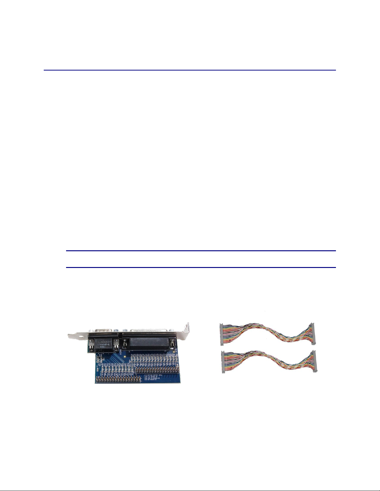
A/V Option Kit Contents
Figure 1. A/V Option Figure 2. Ribbon Cables
The Osprey 450e A/V Option kit contains the following:
A/V Option Board
2 ribbon cables
ViewCast 3
Osprey 450e A/V Option Installation Guide
Pin
Description
Pin
Description
1
D Right +
14
D Right -
2
D Right Shield
15
D Left +
3
D Left -
16
D Left Shield
4
C Right +
17
C Right -
5
C Right Shield
18
C Left +
6
C Left -
19
C Left Shield
7
B Right +
20
B Right -
8
B Right Shield
21
B Left +
9
B Left -
22
B Left Shield
10
A Right +
23
A Right -
11
A Right Shield
24
A Left +
12
A Left -
25
A Left Shield
13
Empty
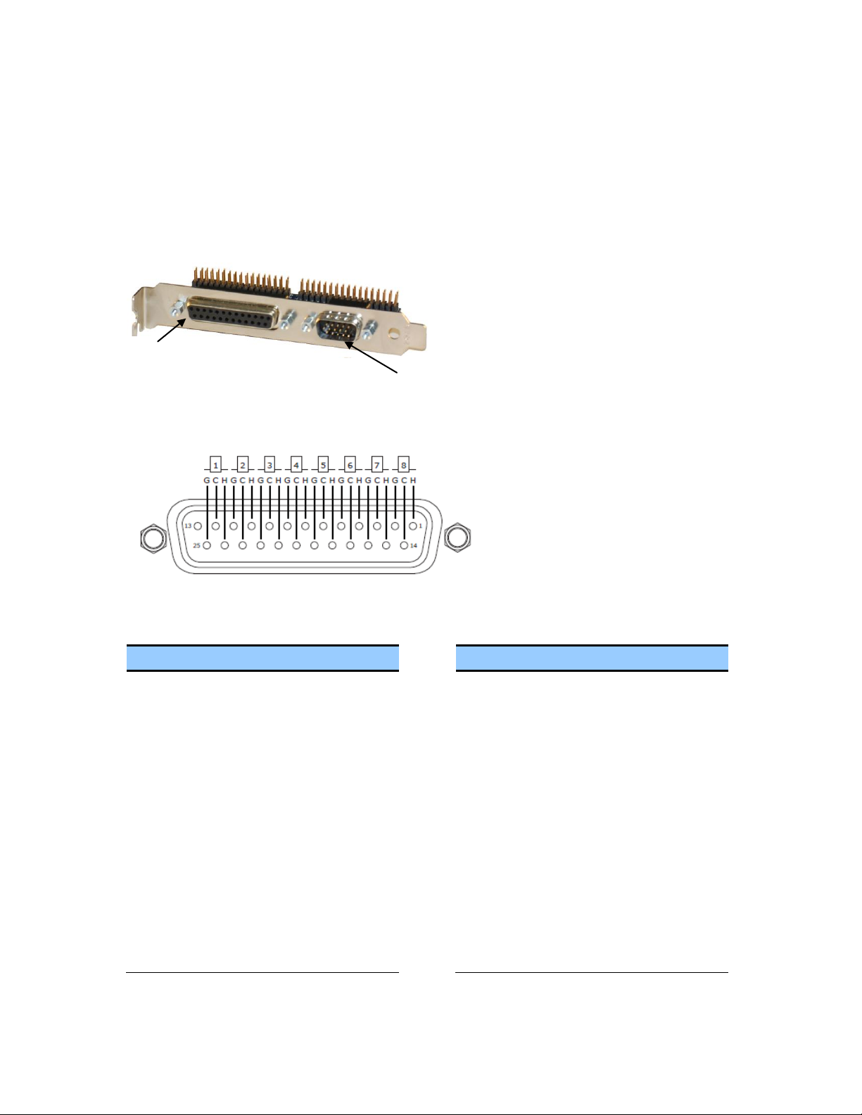
DB25
DB15
H = Hot
C = Cold
G = Ground
A/V Option Board
The Osprey 450e A/V Option Board (Figure 3) has two connectors, an industry standard DB25 female
connector and a DB15 male connector (see pinout tables). Balanced audio is provided on the DB25
connector and it is TASCAM DTRS compatible.
Figure 3. A/V Option Board (Front View)
DB25
DB 25 Pinouts
ViewCast 4

DB15
Pin
Composite
Component
Y/C
1
A4
A-Pr
A-S-Chroma
2
B3
B-Pb
3
C2
C-Y
C-S-Luma
4
C4
C-Pr
C-S-Chroma
5
D3
D-Pb
6
A3
A-Pb
7
B2
B-Y
B-S-Luma
8
B4
B-Pr
B-S-Chroma
9
C3
C-Pb
10
D2
D-Y
D-S-Luma
11
A2
A-Y
A-S-Luma
12
Shield/Gnd
Shield/Gnd
Shield/Gnd
13
Shield/Gnd
Shield/Gnd
Shield/Gnd
14
Shield/Gnd
Shield/Gnd
Shield/Gnd
15
D4
D-Pr
D-S-Chroma
DB 15 Pinouts
Osprey 450e A/V Option Installation Guide
ViewCast 5

Osprey 450e A/V Option Installation Guide
1.
Locate Audio pin 1 on the Osprey 450e card (Figure 4).
2.
An arrow is located at one end of the ribbon cable (Figure 5). Align the arrow to Audio pin 1.
Audio
Pin 1
Video
Pin 1
Arrow
Connecting the A/V Option to the Osprey 450e
NOTE: It is best to use a grounding strap when performing these steps.
To connect the A/V option:
Figure 4. Osprey 450e Video Capture Card
Figure 5. Ribbon Cable End
ViewCast 6

3.
Connect the ribbon cable by pressing down firmly.
4.
Locate Audio pin 1 on the A/V option board (Figure 6).
Figure 6. A/V Option Board
5.
Locate the arrow at the other end of the ribbon cable. Align this arrow to Audio pin 1 on the
A/V option board.
6.
Connect the ribbon cable by pressing down firmly.
7.
Repeat steps 1 through 6 for video.
NOTE: Make sure the ribbons do not cross.
8.
Install the driver and follow the prompted instructions.
Audio
Pin 1
Video
Pin 1
Osprey 450e A/V Option Installation Guide
Figure 7. Complete Assembly
NOTE: The recommended procedure is to install the driver software prior to installing the
Osprey video capture card in the computer. As soon as you install an Osprey card in the PC,
the card and its drivers are detected automatically.
ViewCast 7

9.
Turn off the computer and install the Osprey 450e and the A/V Option Card.
WARNING!: Be sure to install the card in the PCI Express slot. This slot is usually black.
Refer to Figure 8 as a guide. Placing the card in the wrong slot can damage the card.
Figure 8. PCI Express Slot
10.
Power up the computer. The OS will detect the newly present Osprey card, and begin to
activate the driver.
11.
When the installation is complete, reboot the system.
Osprey 450e A/V Option Installation Guide
ViewCast 8

Osprey 450e A/V Option Installation Guide
1.
Select Video Filter on Device 1A (Figure 9). The Property page displays (Figure 10).
Configuring the additional A/V inputs
The Osprey 450e has four independent channels which are denoted by A, B, C, and D. Each channel
can support up to four composite inputs, a component input, and a Y/C input. With the addition of
the A/V option and component panel, the Osprey AVStream Driver enables you to select any of
these as physical inputs to each channel.
As an example, the driver lists Osprey 450 Device 1A, 1B, 1C and 1D. The number “1” indicates the
first physical Osprey 450e card in a system. A second card is listed as Osprey 450 Device 2A, 2B, and
so on.
Figure 9. Property Page
To configure the A/V inputs:
ViewCast 9

Figure 10. Video Input Drop-Down List
2.
Click on the Video Input drop-down list to display all of the available video inputs for channel
A, Composite1, Composite2, Composite3, Composite4, Y/C (S-Video) and Component.
NOTE: The Osprey 450e can capture video from only one of the four composite video
inputs at any given time.
See the Osprey driver manual for information on changing the inputs.
3.
Click OK.
Osprey 450e A/V Option Installation Guide
ViewCast 10

Osprey 450e A/V Option Installation Guide
Connecting to the optional panels
The optional panels include the cables that connect to the A/V option connectors or the Osprey
450e video capture card and a standard 19-inch rack panel. Cables are removable from the panels.
Figure 11. 95-00463 Osprey 450e Component Video Panel
On the Component panel, Composite 2, Composite3 and Composite4 are indicated by A2, A3, and
A4 for the A channel. Composite1 (A1) would be the physical input on the bracket of the Osprey
450e video capture card. Y/C (S-Video) is indicated by S-Luma and S-Chroma. Component is
indicated by Y, Pb and Pr.
Figure 12. 95-00462 Osprey 450e Balanced Audio Panel
The balanced audio panel brings out 4 stereo pairs of balanced audio from the A/V option DB25
connector.
Figure 13. 95-00460 Osprey 450e/440 Breakout Panel
The Osprey 450e/440 breakout panel extends the connector on the Osprey 440 or 450e video
capture card to the panel. This includes the 4 composite video connectors (BNC) and the 4 pairs of
unbalanced stereo audio (RCA) from the breakout cable.
ViewCast 11

viewcast.com
© 2010 ViewCast Corporation. ViewCast®, Niagara® (and design)TM are registered trademarks of ViewCast Corporation or its subsidiaries. All
other trademarks are the property of their respective owners. Product specifications and availability may change without notice.
40-02090-01-A
 Loading...