

ViewCast Osprey-450e User Manual
Osprey® 240e/450e User Guide
AVStream Driver Version 4.6

© 2012 ViewCast Corporation. All rights reserved.
Osprey® and SimulStream® are registered trademarks of ViewCast Corporation Microsoft®, Windows®, Windows Server ®2003, AVStream®,
DirectShow®, Intel® CoreDuo®, and Windows Media® Encoder are trademarks or registered trademarks of Microsoft Corporation. Any other
product names, trademarks, trade names, service marks, or service names owned or registered by any other company and mentioned herein
are the property of their respective companies.
No part of this specification may be reproduced, transcribed, transmitted or stored in a retrieval system in any part or by any means without
the express written consent of ViewCast Corporation. ViewCast Corporation reserves the right to change any products herein at any time and
without notice. ViewCast Corporation makes no representations or warranties regarding the content of this document, and assumes no
responsibility for any errors contained herein.
UL Statement
Underwriters Laboratories Inc. has not tested the performance or reliability of the security or signaling aspects of this product. UL has only
tested for fire, shock and casualty hazards as outlined in UL’s standard for safety UL 60950-1. UL certification does not cover the performance
or reliability of the security or signaling aspects of this product. UL MAKES NO REPRESENTATIONS, WARRANTIES OR CERTIFICATIONS
WHATSOEVER REGARDING THE PERFORMANCE OR RELIABILITY OF ANY SECURITY OR SIGNALING RELATED FUNCTIONS OF THIS PRODUCT.
To maintain UL compliance, this product to be used only with UL Listed computers that include instructions for user installed accessories.
FCC Notice:
WARNING: Use shielded cables to connect this device to peripherals in order to maintain compliance with FCC radio emission limits.
WARNING: Modifications to this device not approved by ViewCast Corporation could void the authority granted to the user by the FCC to
operate the device.
The Osprey 240e video capture card has been tested and found to comply with the limits for a Class B digital device, pursuant to Part 15 of the
FCC Rules. These limits are designed to provide reasonable protection against harmful interference in a residential installation. This equipment
generates uses and can radiate radio frequency energy and, if not installed and used in accordance with the instructions, may cause harmful
interference to radio communications. However, there is no guarantee that interference will not occur in a particular installation. If this device
does cause harmful interference to radio or television reception the user is encouraged to try to correct the interference by one or more of the
following measures:
Reorient or relocate the receiving antenna.
Increase the separation between the equipment and receiver.
Connect the computer into an outlet on a circuit different from that to which the receiver is connected.
Consult the dealer or an experienced radio/TV technician for help.
If the above measures are unsuccessful, please consult the dealer or manufacturer of your radio or television receiver, or speak with an
experienced radio/TV technician.
Note: This reminder is provided to call to the CATV installer’s attention Section 820-40 of the NEC, which provides guidelines for proper
grounding and, in particular, specifies that the cable ground shall be connected to the grounding and, in particular, specifies that the cable
ground shall be connected to the grounding system of the building, as close to the point of cable entry as practical.
The Osprey 450e video capture card has been tested and found to comply with the limits for a Class A digital device, pursuant to Part 15 of the
FCC Rules. These limits are designed to provide reasonable protection against harmful interference when the equipment is operated in a
commercial environment. This equipment generates, uses, and can radiate radio frequency energy and, if not installed and used in accordance
with the instruction manual, may cause harmful interference to radio communications. Operation of this equipment in a residential area is
likely to cause harmful interference in which case users will be required to correct the interference at their own expense.
Shielded Cables: Connections between this device and peripherals must be made using shielded cables in order to maintain compliance with
FCC radio emission limits.
Modifications: Modifications to this device not approved by ViewCast Corporation could void the authority granted to the user by the FCC to
operate the device.
Note to CATV Installer: Section 820-40 of the NEC provides guidelines for proper grounding and, in particular, specifies the cable ground shall
be connected to the grounding system of the building, as close to the point of cable entry as practical.
Product Disposal Information
Dispose of this product in accordance with local and national disposal regulations (if any), including those governing the recovery and
recycling of waste electrical and electronic equipment (WEEE).
RoHS Compliant: ViewCast Corporation is committed to compliance with the European directive on the Restriction of the Use of Certain
Hazardous Substances in Electrical and Electronic Equipment, Directive 2002/95/EC, the RoHS directive.
For current RoHS statement, visit www.viewcast.com.
ViewCast Corporation 3701 W. Plano Parkway, Suite 300, Plano, TX 75075-7840 USA

Osprey 240e/450e User Guide
Contents
Overview ............................................................................................................................. 1
Warranties .......................................................................................................................... 1
System requirements .......................................................................................................... 2
Minimum system requirements ......................................................................................... 2
Installation Steps ............................................................................................................... 3
Installing the driver ............................................................................................................. 3
Custom installing AVStream ............................................................................................... 4
Installing the video capture card ........................................................................................ 4
Setting Driver Properties ................................................................................................... 7
OspreyConfig’s initial processing sequence ....................................................................... 8
Understanding the device properties window ................................................................. 11
Devices and global controls ........................................................................................ 13
Input tab ............................................................................................................................ 14
Osprey 450e AV option hardware add-on-device ...................................................... 16
Video input .................................................................................................................. 17
Video standard ............................................................................................................ 18
Input Format: analog inputs ....................................................................................... 19
VideoCheck ................................................................................................................. 20
VideoGraph ................................................................................................................. 20
VbiGraph ..................................................................................................................... 21
Video Proc Amp tab .......................................................................................................... 22
Video Decoder tab ............................................................................................................ 24
RefSize tab ......................................................................................................................... 26
Horizontal Format ....................................................................................................... 27
Horizontal Delay .......................................................................................................... 28
Source Width .............................................................................................................. 29
Reference Size for Crop and Logo Placement ............................................................. 30
525-Line (NTSC) Vertical Format ................................................................................. 31
Filters tab .......................................................................................................................... 32
SimulStream ................................................................................................................ 33
Deinterlace .................................................................................................................. 36
Currently Using group ................................................................................................. 38
Adaptive Deinterlace window ..................................................................................... 39
ViewCast iii

Contents
Device tab ......................................................................................................................... 42
No-Video Test Pattern ................................................................................................ 43
Buffers Requested ....................................................................................................... 43
Diagnostic logging ....................................................................................................... 44
Device Info .................................................................................................................. 46
Board Numbering ........................................................................................................ 46
Extras ........................................................................................................................... 49
Captions tab ...................................................................................................................... 50
Pin Select ..................................................................................................................... 51
Render NTSC Closed Captions On Video ..................................................................... 52
Render Logical White As ............................................................................................. 52
CC Pin .......................................................................................................................... 53
Logo tab ............................................................................................................................ 54
Pin Select ..................................................................................................................... 56
File and Color .............................................................................................................. 56
Enable Key Color ......................................................................................................... 57
Weighting .................................................................................................................... 58
Position and Size ......................................................................................................... 58
Size and Crop tab .............................................................................................................. 60
Pin Select ..................................................................................................................... 61
Reference Size ............................................................................................................. 61
Granularity .................................................................................................................. 62
Enable Cropping .......................................................................................................... 63
Default Output Size ..................................................................................................... 65
AVStream driver reference information ...........................................................................67
Post-Processing mode ....................................................................................................... 69
Efficient Video Rendering ................................................................................................. 71
Preview Pin to Video Renderer ................................................................................... 71
Preview Pin to Overlay Mixer to Video Renderer ....................................................... 71
Preview Pin to VMR7 .................................................................................................. 72
Preview Pin to VMR9 .................................................................................................. 73
Some Data Points ........................................................................................................ 73
Video standards and sizes ................................................................................................. 75
Color formats .............................................................................................................. 75
YUV format details ...................................................................................................... 76
Closed captioning (CC) ................................................................................................ 77
Captioning via CC or VBI pins ...................................................................................... 77
Direct CC rendering on video ...................................................................................... 78
CC streaming interface ................................................................................................ 79
Vertical Interval Timecode (VITC) ............................................................................... 79
Vertical Blanking Interval (VBI) capture ...................................................................... 80
iv ViewCast

Osprey 240e/450e User Guide
Audio driver .......................................................................................................................81
Selecting the audio source and input volume .................................................................. 81
Audio properties page ...................................................................................................... 83
Audio formats ............................................................................................................. 84
Audio playback ............................................................................................................ 84
Audio configuration .................................................................................................... 84
Mono Source Mode .................................................................................................... 84
Dual Mono .................................................................................................................. 84
Audio level .................................................................................................................. 86
Appendix A: Osprey hardware specifications .................................................................87
Osprey 240e ...................................................................................................................... 87
Environmental specifications ...................................................................................... 87
Osprey 450e ...................................................................................................................... 89
Appendix B: Osprey 450e audio cable .............................................................................91
Appendix C: Troubleshooting ..........................................................................................93
Color bars on video screen ............................................................................................... 93
Scrambled video image ..................................................................................................... 93
Poor video quality at large frame sizes ............................................................................. 94
Multiple horizontal lines across video image ................................................................... 94
Cannot play back recorded audio ..................................................................................... 94
Audio recording control comes up with wrong device and wrong inputs ....................... 94
Index ..................................................................................................................................97
ViewCast v


Osprey 240e/450e User Guide
Limited Warranty
ViewCast warrants its hardware products against
defects in material and workmanship under normal use
for the period of one year (12 months) from date of
sale. Where specific warranties exist that provide more
substantial coverage, notwithstanding the warranty
provisions herein, such product warranties control and
preempt or supersede the warranty provisions herein.
Reseller Pass Through of
Standard Limited Warranties.
Resellers pass the ViewCast standard limited warranties
for the products through to the customer without
modification. Any modification of a product voids the
ViewCast warranties or any other existing or available
warranty.
Overview
Thank you for purchasing the ViewCast Osprey 240e/450e video capture card. This user guide provides
step-by-step instructions for installing and using your new video capture card. For the latest ViewCast
product information and news, visit our website at www.viewcast.com.
Warranties
For complete warranty details, refer to the specific warranty included with each product. General
warranty information includes the following:
ViewCast 1

Overview
System requirements
The following system requirements relate to your Osprey® video capture card only. The video capture or
encoding applications you use will likely require a much more powerful system than that which is listed
below. Please consult your software documentation for applicable system requirements.
Minimum system requirements
Direct Mode: 2 GHz Intel® Pentium® 4 processor or equivalent
PostProcessing Mode and SimulStream®: 2 GHz Intel® Pentium® 4 processor or equivalent, 3
GHz recommended
Microsoft® Windows® Professional or Home Edition, Windows Server® 2003
Up to 7.5 MB of available hard disk space
256 MB of RAM, 512 MB recommended
One available PCI Express® slot
2 ViewCast

Osprey 240e/450e User Guide
Installation Steps
In all cases, use the setup.exe program on the product CD or in the web package if you downloaded it.
The setup program automates the Plug and Play steps needed to install the drivers and ensures they are
performed correctly. It also installs the bundled applets and User’s Guide. If you have multiple Osprey
capture cards in the system it configures all of the boards at the same time.
We recommend this method especially if Osprey software does reside on your host computer. After the
install is run, the software detects the card and its drivers initiate automatically.
If you are updating Osprey software, first uninstall the previous software version, reboot your computer,
and then install the update.
Installing the driver
Insert the Osprey Software CD into your CD-Rom drive. The main menu for the Osprey software appears
if you enable autoplay. If the main menu does not automatically appear, click on the Window’s
computer icon and select the CD-Rom and the setup.exe icon. The Osprey A/VStream – Install Shield
Wizard engages and guides you through the installation process.
ViewCast 3
Installation Steps
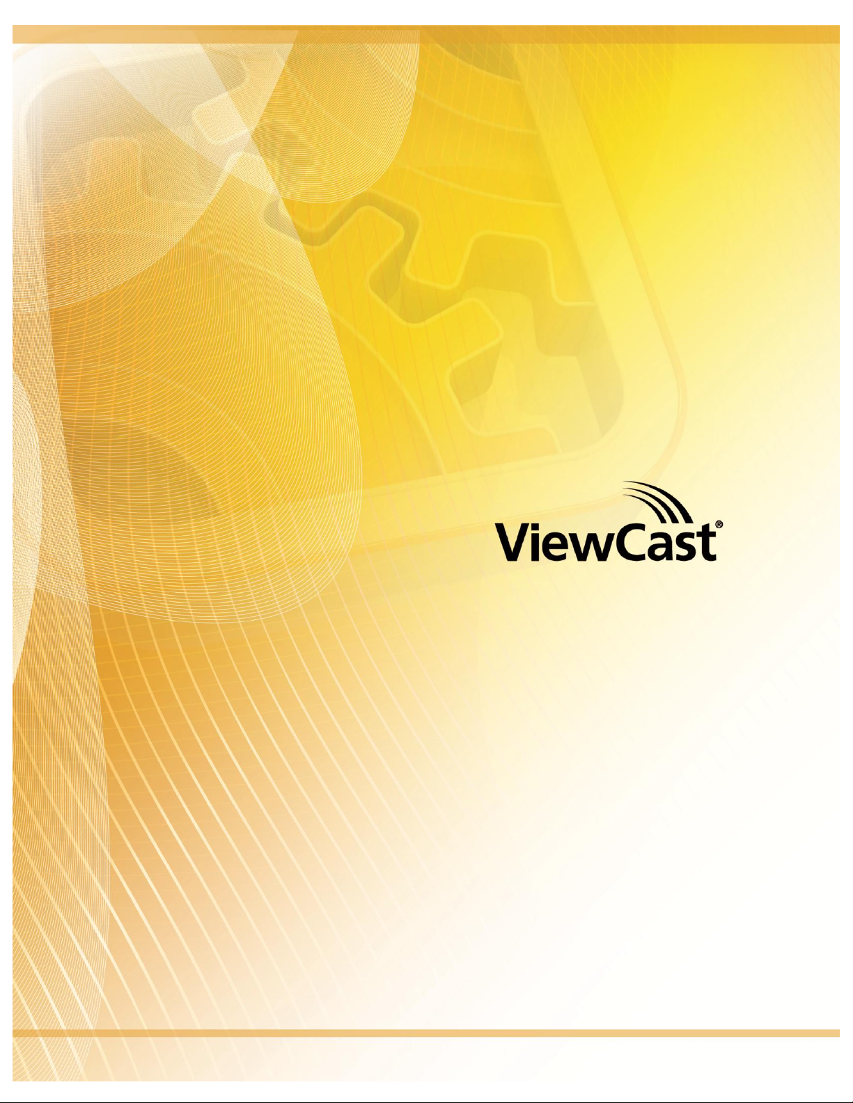
Custom installing AVStream
During the installation process, if you choose a Custom installation, your options are limited (Figure 1).
Figure 1. Osprey 240e Custom Setup screen
This window allows you to choose individual components you may want to install. You can also change
the location where components install.
Installing the video capture card
This manual covers one class of Osprey devices that include two PCI Express cards.
Class 6: o-240e, o-450e and related non-DSP PCI Express products
Both cards use the same driver. If you add a card from a different class, then you need to install the
driver for that card.
When you add or move boards after the AVStream 4.6 driver is already installed, there are two
possibilities:
You add a board of a different class from what is already in the machine. For example, an
Osprey 240e is already in the machine with the current driver installed, and you want to add
an Osprey 530. For this case, you have to obtain and install the driver install package for the
new board.
You move a board from one slot to another, or if you add another board of the same type.
For example, you might have an Osprey 240e in the machine, and want to add another
Osprey 240e. In this case, the following sequence begins.
4 ViewCast
Osprey 240e/450e User Guide
1.
Power down and unplug your computer.
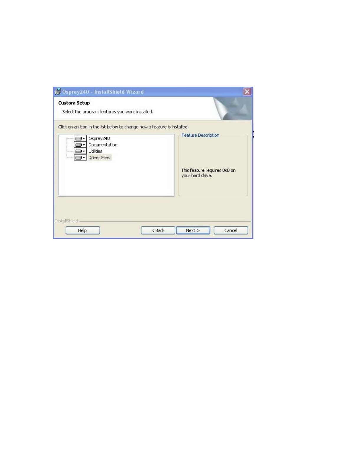
2.
Remove the computer’s cover and locate an empty PCI Express slot.
WARNING! Be sure to install the card in the PCI Express slot. This slot is
usually black. Refer to the following diagram as a guide. Placing the card in
the wrong slot can damage the card.
3.
Remove the cover screw from the empty PCI Express slot’s cover, set the screw aside.
4.
Remove the slot cover.
5.
Remove the Osprey video capture card from its anti-static bag.
6.
Insert the Osprey card into the desired PCI Express slot and make sure it is seated evenly.
7.
Secure the back panel of the card with the slot’s cover screw.
8.
Replace the computer cover.
9.
Plug in and turn the computer on.
All computer cards are sensitive to electrostatic discharge. Slight electrostatic discharges from
clothing or even from the normal work environment can adversely affect these cards. By following
these simple guidelines, however, you can minimize the chance of damaging the Osprey video
capture card.
Handle cards only by the non-conducting edges.
Do not touch the card components or any other metal parts.
Wear a grounding strap while handling the cards (especially when located in a high
static area).
Properly ground your computer to avoid static discharge.
Ensure the workstation is powered off before installing any components.
If you are not familiar with how to install a PCI Express
documentation for more complete, step-by-step instructions.
®
bus card, refer to the system’s
Install the card only in UL Listed computers that include instructions for user-installed
accessories
To install the video capture card:
ViewCast 5
Installation Steps
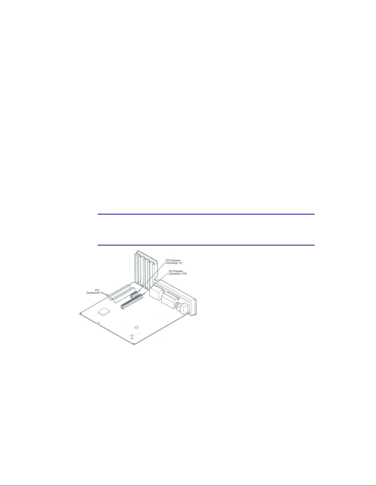
1.
Click Continue Anyway. The Controller installing window displays, and the text inside this
window changes to Osprey Video Capture Device, Installing ... Then the Digital Signature
Not Found window appears on top of it.
2.
Click Continue Anyway. The Completing the Found New Hardware window displays.
3.
Click Finish. The Digital Signature Not Found window displays.
This window displays once for each Osprey board you are installing. The Systems Setting
Change window displays.
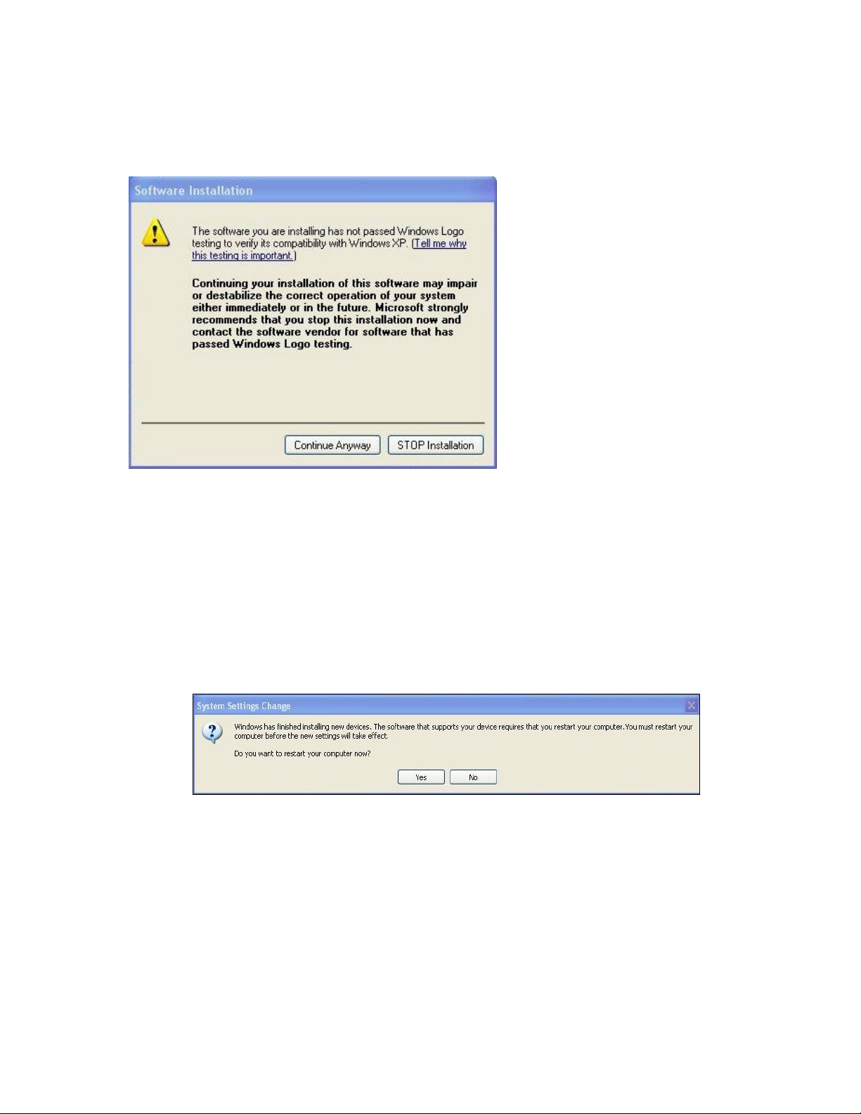
4.
Click Finish and click Yes to restart the system now (Figure 3).
Figure 3. System Settings Change Window
The New Hardware Wizard runs and the Found New Hardware window appears followed by the Digital
Signature Not Found window (Figure 2)
Figure 2. Digital Signature Not Found Window
6 ViewCast
Osprey 240e/450e User Guide
Setting Driver Properties
After installing the Osprey card and AVStream driver, you need to access the card’s settings and possibly
modify them to fit your needs. This manual takes you step-by-step visually through the card settings.
Start by opening the Osprey Config utility. Afterwards, we can explore the driver.
You need to use a DirectShow application such as Microsoft Windows Media® Encoder or
RealProducer®. We also access card property pages through Osprey Config, the utility bundled with our
4.6 driver suite. Once installed you can see the card’s default settings and change them as needed.
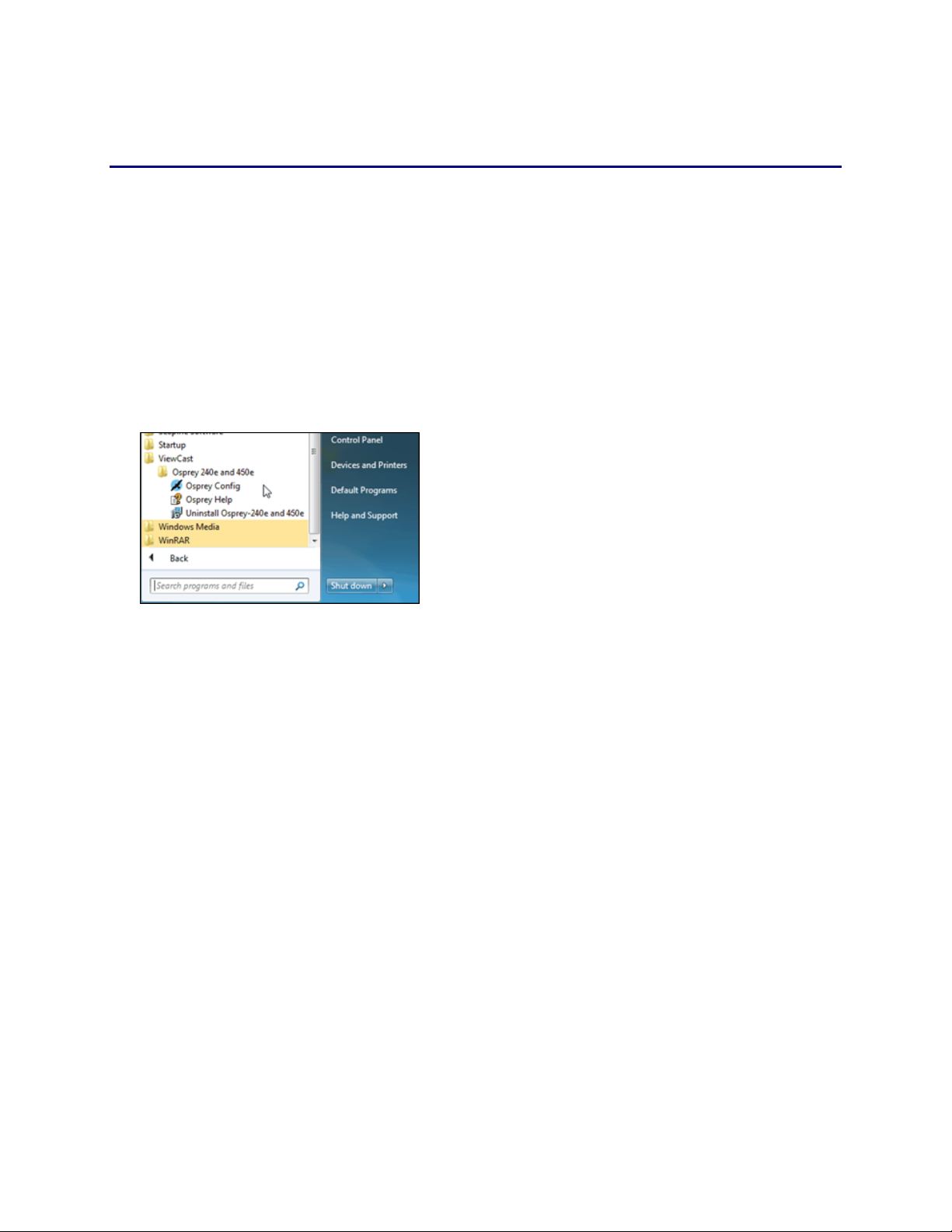
To open Osprey Config click All Programs in the Start menu of your Windows computer ViewCast
Osprey 240e and 450e Osprey Config (Figure 4).
Figure 4. Accessing the Osprey Config Utility
Note: Other DirectShow applications can find the property page too. If you use a third-party
application, you will find how to access the card’s settings in the third-party application’s
documentation.
ViewCast 7

Setting Driver Properties
OspreyConfig’s initial processing sequence
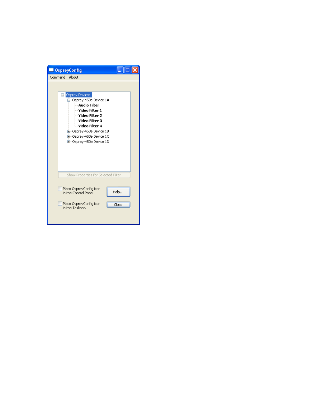
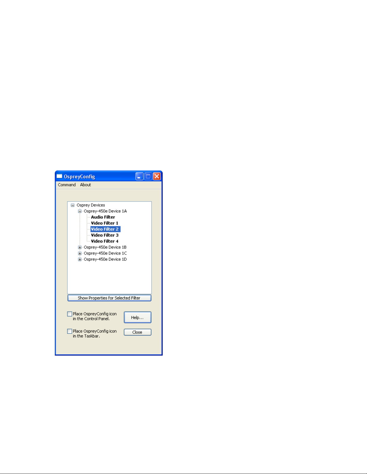
After clicking on the Osprey Config icon, the first screen of the application appears (Figure 5) showing
the cards and devices installed on your computer.
Figure 5. Initial OspreyConfig user interface
In this example, the computer in use has one card and four devices. The card can take a single input and
stream the content differently, for example, you can use several bit rates, sizes, and formats. Click the +
icon on the left side of the device you wish to configure, to change the properties of that device.
8 ViewCast
Osprey 240e/450e User Guide
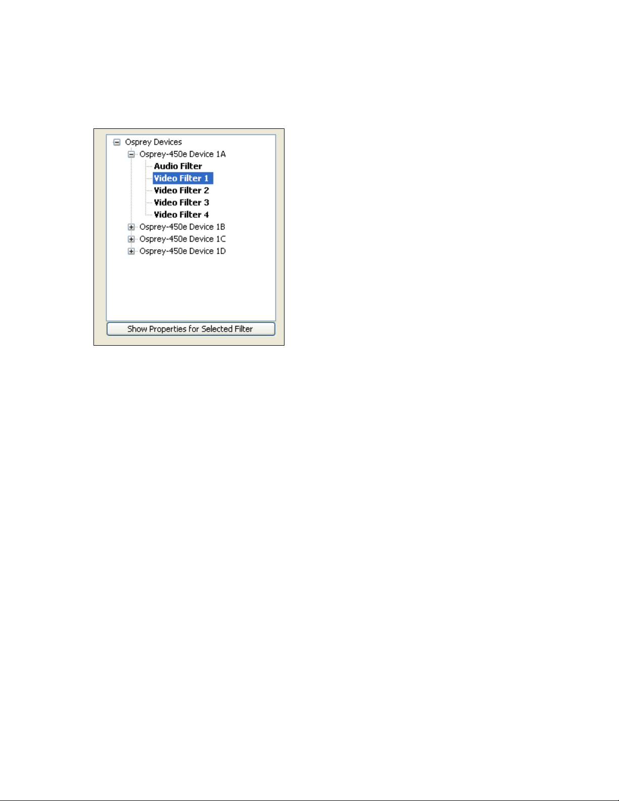
Figure 6 shows the user interface that appears when you select a filter. We expanded the Osprey 450e
Device 1A and selected Video Filter. We’ll continue with this device unless we indicate otherwise.
Figure 6. Selecting a device for configuration
ViewCast 9
Setting Driver Properties
When you choose Device 1A and Video Filter 1, the Show Properties for Selected Filter button becomes
active (Figure 7).
Figure 7. Control used to open the properties page
10 ViewCast
Osprey 240e/450e User Guide
Understanding the device properties window
Osprey’s device properties window enables you to view and change the default settings of the 4.6
driver. Once you are familiar with the video card’s properties, you can make changes to get the
optimum performance from your card and change settings in real time.
Device properties are visible through tabs to select different controls (Figure 8). The 4.6 driver includes
changes from previous versions - the tabs have changed. They now take advantage of the 4.6 driver’s
advances and added functionality.
Figure 8. Osprey Video Device Properties window tabs
The Osprey 240e and Osprey 450e use the same driver. The same Video Device properties appear
whether you choose the Osprey 240e or the Osprey 450e. If you have other Osprey cards, they can still
coexist on your PC, but they use a separate version of the drivers provided with the card. You need the
driver version for video capture cards you use.
ViewCast 11

Setting Driver Properties
Input
Select the video input, NTSC / PAL / SECAM video standard and
Input Format
Video Proc Amp
Set brightness, contrast, saturation, hue, gamma, and sharpness
Video Decoder
Select the video standard – NTSC, PAL, SECAM
RefSize
Set the reference size for cropping
Filters
SimulStream®, processing mode, gamma, deinterlace, and
inverse telecine*
Device
Test Pattern, Capture Buffers, Diagnostic Logging
Captions
Set up on-video closed caption rendering
Logo
Set up on-video logos
Size and Crop
Set the default size, enable cropping, set the cropping rectangle
The Osprey 240e and 450e cards have the following tabs:
* Telecine refers to the technology used to transfer or repurpose analog film into electronic media.
Some of the 4.6 drivers’ controls work interactively and changes in value immediately update the video.
Examples include brightness, contrast, hue, saturation, and sharpness.
12 ViewCast
Osprey 240e/450e User Guide
Devices and global controls
The Osprey 240e and Osprey 450e video capture cards can present multiple output streams from a
single input device. For example, a company may wish to do a webcast globally to resellers, users, or
potential customers. Using the Filters tab, you can set up different output streams with different bit
rates to accommodate users with different bandwidths.
Some changes may affect the filter, such as cropping, logos, and captions. For example, changes to the
Osprey 450e Device 1A, Filter 2 only affect that filter (Figure 9).
Change the values on Video Proc Amp, Video Decoder, Input, Filters, Device, and/or RefSize tabs and the
effect is global to the card. All characteristics on each device on the card change to those changed on a
single device. This is limited to the card on which the device changed. If you make changes on an Osprey
240e card residing with an Osprey 450e card, a change on the Osprey 240e does not affect the Osprey
450e devices.
Figure 9. OspreyConfig utility to access devices
DirectShow® discussions refer to pins and filters. These terms require technical experience with
Microsoft’s DirectX® 9 Software Developer’s Kit. References on tabs in the Osprey driver relate to terms
used by Microsoft’s streaming video software application. They exist for users with a high degree of
technical expertise. You can simply ignore them and use the property tabs as discussed in this manual.
ViewCast 13
Setting Driver Properties
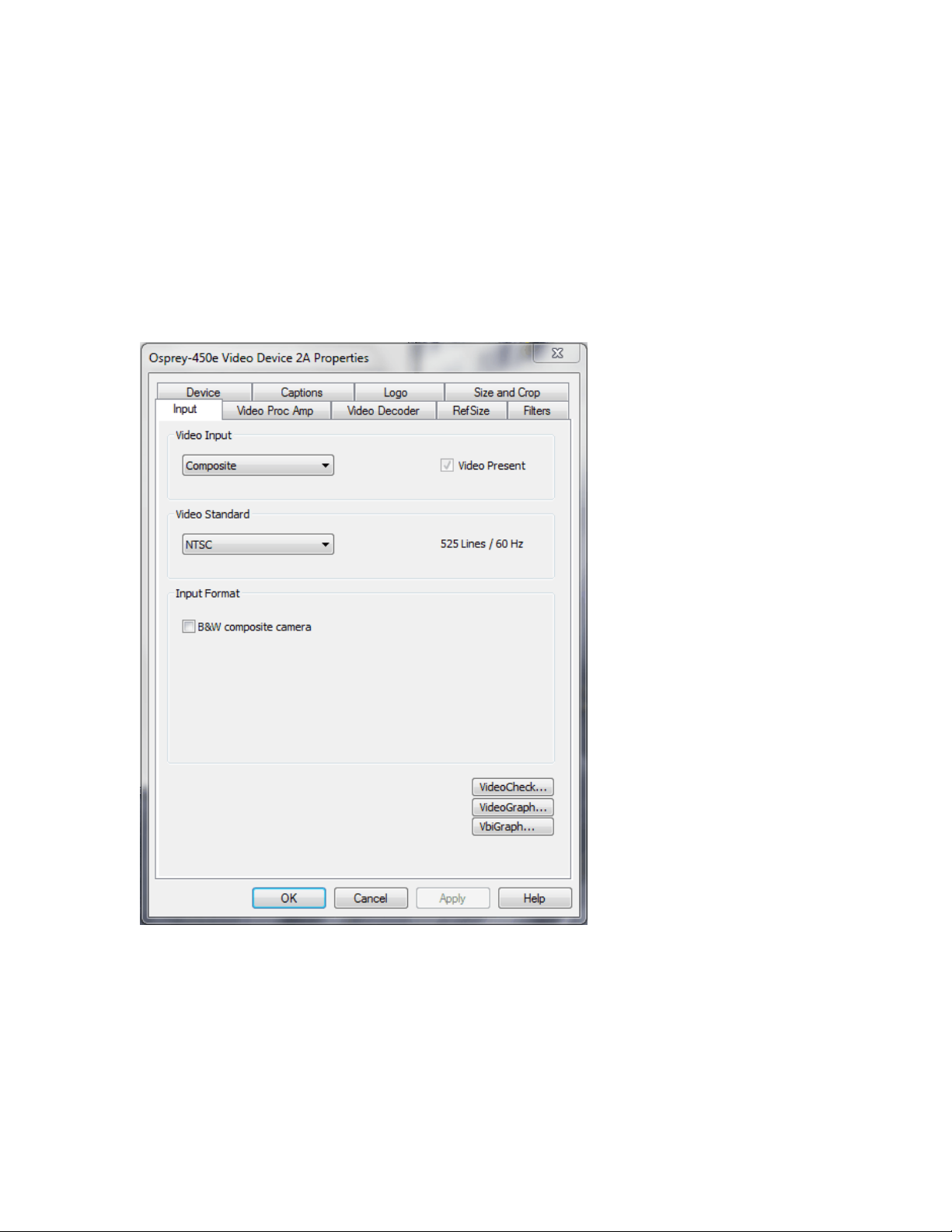
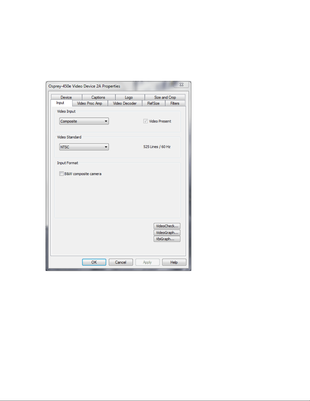
Input tab
The source of data from an Osprey 240e/450e that streams to the Internet can come from a number of
devices such as DVD players, digital cameras, camcorders, and so forth.
Figure 10. Input tab
The controls on the Input tab of the driver properties card have a global effect on the Osprey capture
card on which they reside. If you have multiple Osprey cards, and you want to make global changes, you
have to make the change on each card.
14 ViewCast

Osprey 240e/450e User Guide
Video Input
The Video Input section of the tab allows you to select the video
signal source.
Video Present
This indicator is enabled when video is present.
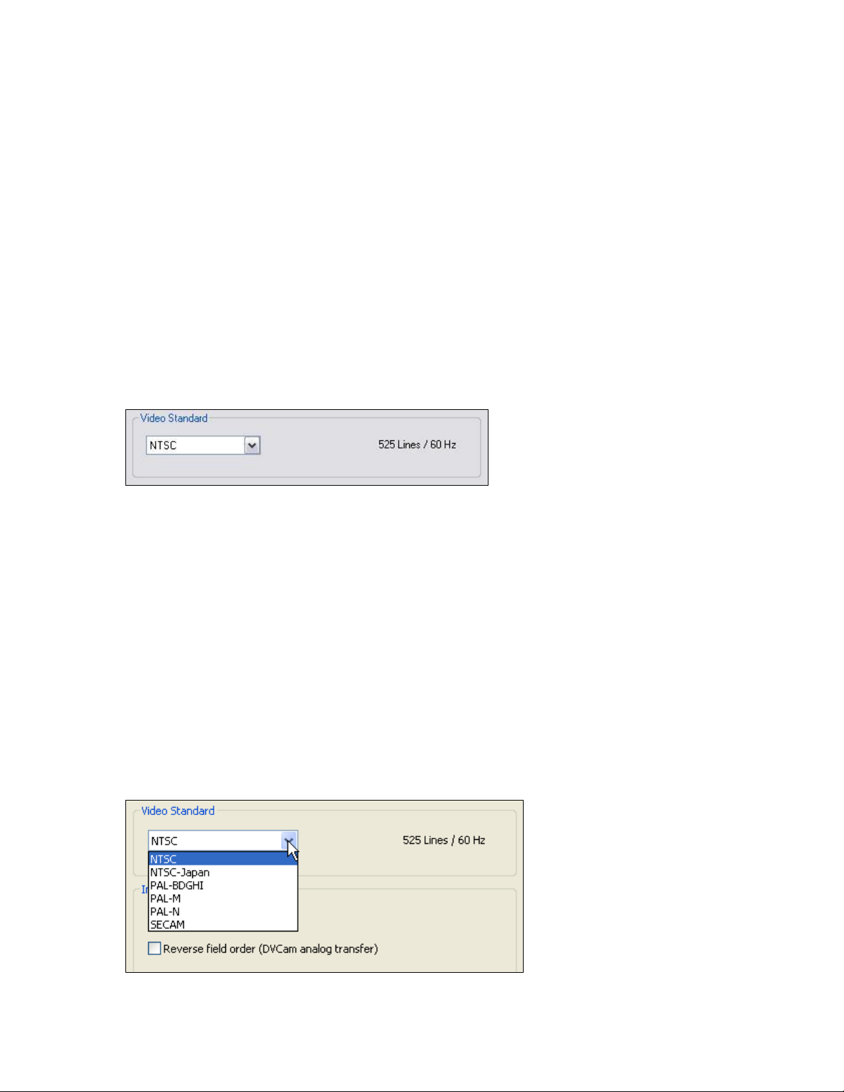
Video Standard
The Video Standard allows you to select the standard different
countries or geographical areas use (Figure 10) from the dropdown list.
Input Format
This control works with digital cameras routing through the
Osprey’s card’s analog input.
VideoCheck
This button opens a simple video monitoring window.
VideoGraph
This button launches a vectorscope/lumascope utility.
VbiGraph
This button opens an applet that displays the raw waveforms of
the video’s Vertical Blanking Interval (VBI).
OK
Click OK to accept the settings.
Cancel
Click Cancel to reject the settings and close the window.
Apply
Click Apply to apply the settings.
Help
Click Help to access the user guide.
The Input tab has the following controls.
ViewCast 15
Setting Driver Properties
Osprey 450e AV option hardware add-on-device
In addition to the standard components built into the Osprey 450e card, you can purchase the Osprey
450e AV Option hardware add-on device.
The AV Option exposes additional inputs for Component and S-Video as well as balanced audio. For
example, when you choose a Filter from standard Osprey 450e Device 1A; the default option provides a
single video capability: Composite.
Note: Use Osprey Config to set balanced audio for Microsoft® Windows Media Encoder.
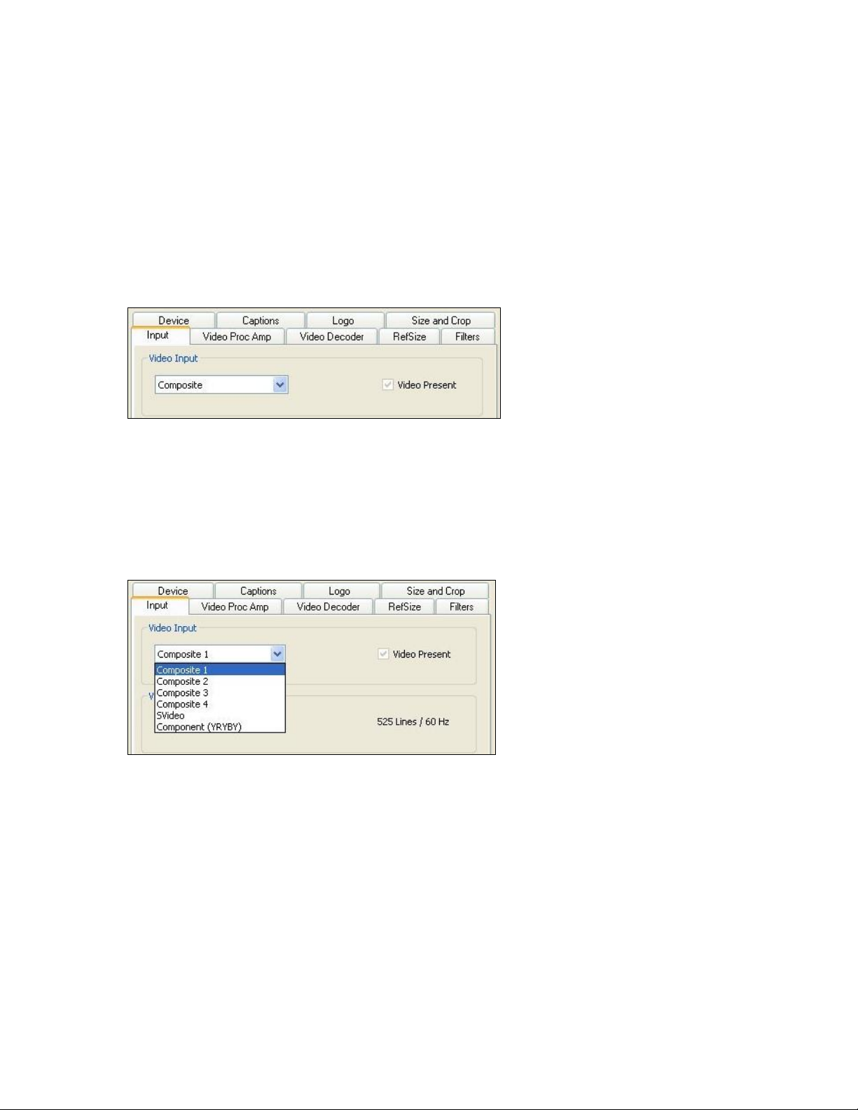
Figure 11. Input tab without AV option
Without the AV hardware option the default input standard is limited to Composite. With the optional
add-on, you also have Composite 1,2,3,4, S-Video and Component YRYBY (Figure 11 and Figure 12).
Note: Separate video, abbreviated S-Video (also known as Y/C) is an analog video signal that
carries the video data as two separate signals. They include luma (~brightness) and chroma
(~color).
Figure 12. Osprey 450e card with optional plug-in
16 ViewCast
Osprey 240e/450e User Guide
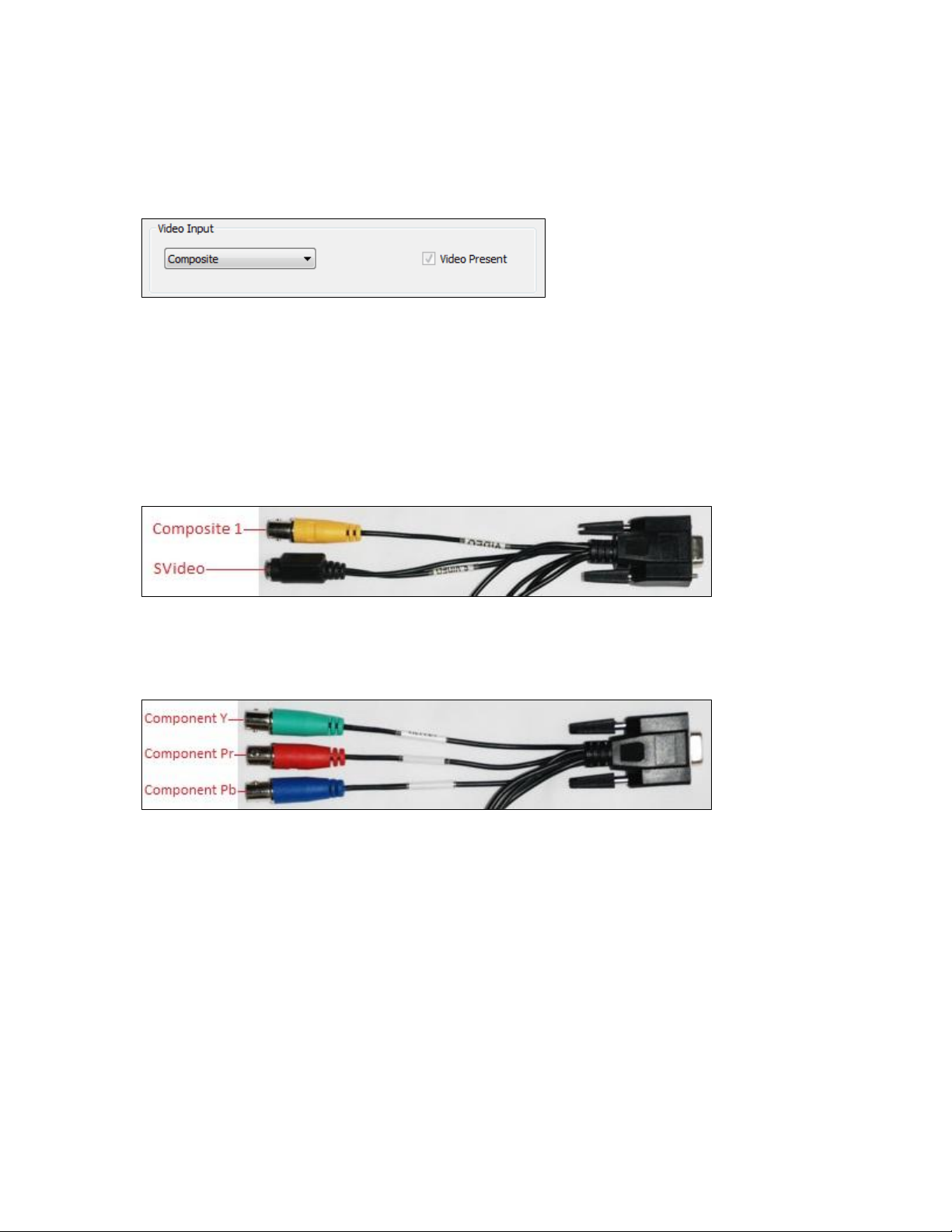
Video input
The Video Input (Figure 16) lets you select the video signal source from a drop-down list.
Figure 13. Video Input field
Osprey 240e
The Osprey 240e is a single channel card. It has multiple video inputs, but you can select only one of
them at a time. The inputs that are selectable depend on the type of dongle used. Two types of dongles
are available for this board – Composite/SVideo, and YPrPb.
The connections for the Composite/SVideo dongle are shown in Figure 14.
Figure 14. Composite/SVideo dongle connections
The YPrPB dongle is primarily for YPrPb (Component) inputs, as shown in
Figure 15. YPrPb dongle connections
The blue Pb input can also be used as a Composite input. The driver should be set to Composite when thePb input
is used this way.
Osprey 450e
The Osprey 450e has four separate independent video channels that can run simultaneously. You can
use the board with or without an optional auxiliary expansion connector.
When the expansion connector is not installed, the only video inputs available are the Composite BNC
inputs on the board’s mounting bracket. The four connectors correspond from top to bottom to
channels A, B, C, and D. In this case, the Video Input control shows just the one input for each channel,
which is selected automatically.
ViewCast 17
Setting Driver Properties
The Osprey -450e’s optional auxiliary expansion connector for video adds three additional inputs, over
three multi-purpose physical connectors for each of the four channels:
Component (YprPb) uses all three of the auxiliary video connectors
S-Video (Y-C) connects an SVideo connector to two of the connectors via an adapter cable
Three additional Composite inputs
The labeling on the expansion panel shows which connectors to use for each purpose. The inputs for
each channel, along with the channel’s bracket connector, can only be used one at a time. The
hardware automatically senses at system start whether the expansion connector is plugged in, and if
it is then six inputs appear in the Video Input drop-down list.
Changes to the video input take effect as soon as you click Apply or OK.
Video standard
Figure 16. Video Standard field
The Video Standard control group is a copy of the controls on the Video Decoder tab.
The North American standard is NTSC. The Japanese standard is NTSC-Japan. The five PAL standards, B,
D, G, H, and I are similar, and are treated the same way by the Osprey driver. The driver also supports
PAL-M and N and SECAM video. The North American standard is NTSC. The Japanese standard is NTSCJapan. The five PAL standards, B, D, G, H, and I are similar and treated the same way by the Osprey
driver. The driver also supports PAL-M and PAL-N and SECAM video. PAL-N is the Argentine standard
with a 3.58 MHz subcarrier. PAL-M is a standard that uses the PAL method of color encoding combined
with an NTSC-type 525-line, 29.97 Hz frame format.
Changes to the video standard take effect as soon as you click Apply or OK. If video is currently
streaming, you will not see correct video unless the signal format on the input is the same as the video
standard you have just selected. If you are changing from a 625-line standard to a 525-line standard and
your video is larger than the maximum size for the 525-line format, video will not restart until you adjust
the video size to an allowed value.
Figure 17. Video Standard drop-down list
18 ViewCast
Osprey 240e/450e User Guide
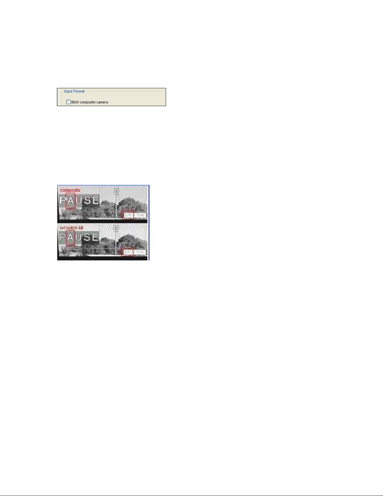
Input Format: analog inputs
Below the Video Standard drop-down list is the Input Format (Figure 18).
Figure 18. Input Format
On the Osprey 240e/450e, when an analog input becomes the media source, the controls provide
adjustments that improve the clarity of video from monochrome sources. When you select a composite
input line and attach a monochrome device, the result is a sharper image, as shown in the notch kill item
in Figure 19. This control is only for true monochrome devices, without color capability.
B&W composite camera
Figure 19. Notch Kill
Black and white input sources are rare these days, but some do exist. For example, you may want to
stream black and white historical film in a documentary film.
ViewCast 19
Setting Driver Properties
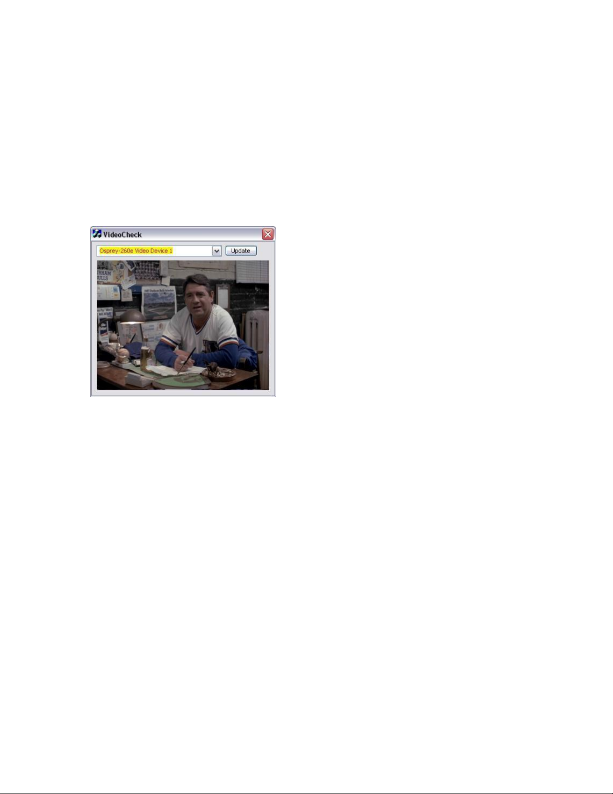
VideoCheck
VideoCheck opens a simple video monitoring window (Figure 20). You can see the immediate effect of
changes to your settings. Most changes show up automatically as soon as you click Apply. You will need
to click the applet’s Update button to see a change that alters the output size of the video.
VideoCheck uses one preview stream of video. If you do not have SimulStream installed, you can only
view one preview stream at a time from each device (this is in addition to the main capture stream). If
VideoCheck does not work, the first thing to check is whether a preview stream is already running on
the device.
Figure 20. VideoCheck
VideoGraph
VideoGraph launches a vectorscope/lumascope utility (Figure 21). VideoGraph is intended to be used
with a color bar signal from a calibrated signal generator. It shows whether the signal and the card’s
Video Proc Amp settings are calibrated to the correct luma and chroma levels.
In Figure 21, the left hand panel shows the luma levels of standard 75 % NTSC color bars. The grey
background shows the expected levels, and the red line shows the actual levels measured. The right
hand panel shows the chroma positions of the six colors. The small colored squares show the expected
positions, and the points on the red signal pattern should line up with them.
If there are discrepancies, you can use the driver’s Brightness, Contrast, Saturation, and Hue controls on
the Video Proc Amp property page to adjust the levels.
If you don’t have a signal generator available, you can get a general idea of how VideoGraph works by
disconnecting the input signal and running it with the 75 % or 100 % no-signal color bar test pattern. The
driver’s test pattern will line up exactly with the VideoGraph’s targets – if the gamma setting is at the
default position. Software-based Video Proc Amp controls alter the test pattern levels; hardware-based
controls do not. The gamma control, and in some cases the hue control, are software-based.
The vertical slider adjusts which video line displays. You may have to move this slide so that a line that
has color bar information is selected.
The horizontal slider moves the horizontal cursor – the vertical line on the luma display. The data
displayed at the lower right – IRE-L, etc – is for the pixel selected by the horizontal cursor. Also, on the
20 ViewCast

Osprey 240e/450e User Guide
chroma display, the small solid rectangular cursor corresponds to the luma cursor – that is, if the luma
cursor is on the red color bar, the chroma cursor will be at or near the red point in the chroma display.
There are also controls to set the background markings for 75 % or 100 % signal levels, and for eight or
seven bars – so that the markings correspond to the type of color bars your signal generator is making.
The Help button on the applet brings up a message box with an alternate, and slightly more technical
description.
Figure 21. VideoGraph
VbiGraph
VbiGraph (Figure 22) opens an applet that displays the raw waveforms of the video’s Vertical Blanking
Interval (VBI). The information on these lines may include closed captions (CC), wide screen signaling
(WSS), vertical interval timecode (VITC), and teletext. The applet is useful as a diagnostic if the expected
data is not being decoded – you can see if the required signal is there at all, whether it is in spec, and
which line it is on.
The controls select the field and line to be displayed. The only time you need the Update button is when
you switch between 525-line and 625-line video standards.
Figure 22. VbiGraph
ViewCast 21
Setting Driver Properties
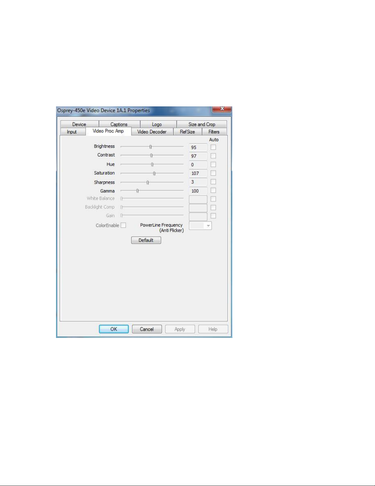
Video Proc Amp tab
Video Proc Amp stands for Video Process Amplifier. It controls various characteristics of streaming
output from Osprey 240e/450e cards. The Video Proc Amp is the second tab from the left of the Device
1A properties (Figure 23).
Figure 23. Video Proc Amp Tab
The Video Proc Amp uses slider controls to adjust brightness, contrast, hue, saturation, sharpness, and
gamma. If you’re using the preview or capture mode in real-time, then you can see your adjustments as
you make them with the Video Proc Amp controls.
22 ViewCast

Osprey 240e/450e User Guide
Brightness and
Contrast
These terms are used for contrast ratio. It’s a measure of a display system, defined as
the ratio of the brightest color (white) to that of the darkest color (black) that the
system can produce. A high contrast ratio is a desired aspect of any display, but with
the various methods of measurement for a system or its part, different measured
values can sometimes produce similar results. The control exists in the event you
need to change the ratio of an incoming signal.
Hue
Hue adjustment only functions for NTSC video. It sets the predominance of color,
classed as red, yellow, green, blue or an intermediate color based on a contiguous
pair of these colors
Saturation
In color theory, saturation or purity refers to the intensity of a specific hue. A highly
saturated hue has a vivid, intense color, while a less saturated hue appears more
muted and grey. With no saturation at all, the hue becomes a shade of grey. You are
able to adjust the saturation level in the event it is altered by a video feed.
Sharpness
This slider has eight positions corresponding to eight hardware filter settings.
Generally, the positions to the left result in smoother video, the positions to the right
result in sharper video. Since each step engages a different combination of discrete
filters, some steps may result in slight differences while other steps may result in
large differences. The range is 0 to 7.
Gamma
You will rarely need to use this control. In simple terms, the input of a feed from a
device into your card may not match the digital output on your screen. The gamma
control enables you to balance the red, blue, and green from the input to output
within the normal range of people’s perceptions.
White Balance
This field is an unused DirectShow feature and is not selectable.
Backlight Comp
This field is an unused DirectShow feature and is not selectable.
Gain
This field is an unused DirectShow feature and is not selectable.
Color Enable
This field is an unused DirectShow feature and is not selectable.
PowerLine
Frequency
(Anti Flicker)
This field is an unused DirectShow feature and is not selectable.
Default
Click Default to return to the default settings.
Auto
This field is an unused DirectShow feature and is not selectable.
OK
Click OK to accept the settings.
Cancel
Click Cancel to close the window.
Apply
Click Apply to apply the settings.
Help
Click Help to access the user guide.
The Video Proc Amp tab has the following controls.
For all of the Video Proc Amp controls the driver maintains one setting per Osprey device. It does not
maintain individual settings for each input or type of input.
When you change the video standard or input you will not see changes in the slider controls – such as
the Hue button becoming disabled – until the driver properties dialog is closed and re-entered.
ViewCast 23
Setting Driver Properties
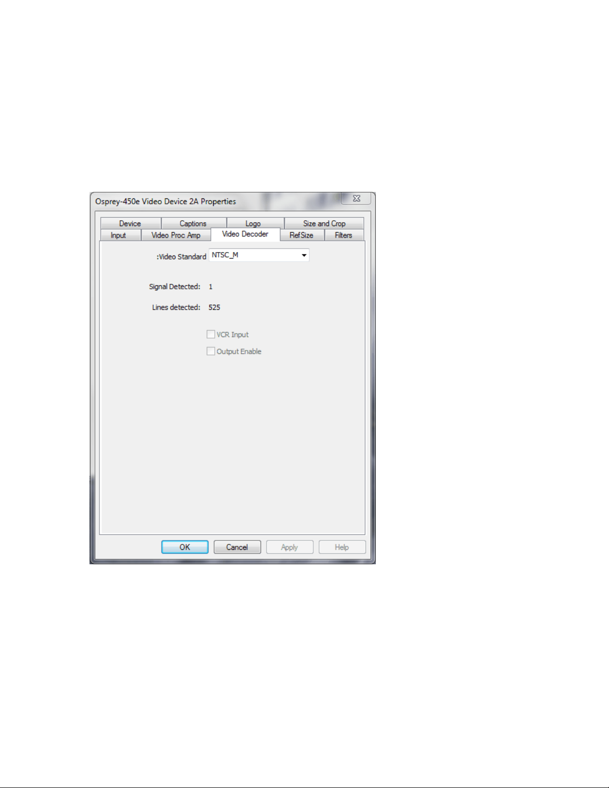
Video Decoder tab
The Video Decoder tab is a Microsoft DirectShow standard control for setting the NTSC/PAL/SECAM
video standards (Figure 24).
Note: These controls are also on the Input tab. Most users find the Input tab more convenient to
use.
Figure 24. Video Decoder tab
Changes apply to all video preview and captures pins on the currently selected device. If you have
multiple Osprey cards, you can set the input individually for each of them. Changes made with this
control take effect immediately. If video is running and you select a standard that does not match the
incoming signal, the video is likely to freeze or glitch until the signal matches the correct standard.
Osprey boards support the Signal Detect (0 or 1) and Lines Detected (525 or 625) status readouts. They
do not support the VCR Input or Output Enabled controls, which will always be disabled.
24 ViewCast
 Loading...