

Ospre y-3 00
User’s Guide

Osprey-300 Capture Card
AVStream Driver Version 3.1
User’s Guide For Windows XP
Releases 3.1 and later.
© Copyright 2004
All Rights Reserved.
ViewCast Corpor a ti o n
17 300 North Dallas Parkwa y, Suite 2000
Dallas, TX 75248 USA
Revised July, 2004
Copyright, Trademark, and FCC Information
Copyright Osprey Technologies, Inc., a wholly owned subsidiary of ViewCast Corporation, copyrights this
document. No part of this specification may be reproduced, transcribed, transmitted or stored in a retrieval
system in any part or by any means without the express written consent of Osprey Technologies, Inc.
Disclaimer
Osprey Technologies, Inc. reserves the right to change any products herein at any time and without notice.
ViewCast Corporation and Osprey Technologies, Inc. make no representations or warranties regarding the
content of this document, and assume no responsibility for any errors contained herein.
Trademark Acknowledgment
Osprey-300 is a trademark of Osprey Technologies, Inc. Microsoft, Windows XP , NetMeeting, NetShow, and
Video for Windows are trademarks or registered trademarks of Microsoft Corporation. Any other product
names, trademarks, trade names, service marks, or service names owned or registered by any other
company and mentioned herein are the property of their respective companies.
FCC Notice
This device has been tested and found to comply with the limits for a Class B digital device, pursuant
to Part 15 of the FCC Rules. These limits are designed to provide reasonable protection against harmful
interference in a residential installation. This device generates, uses, and can radiate radio frequency
energy, and if not installed and used in accordance with the instructions, may cause harmful interference
to radio communications. Howe v er, there is no guarantee that interference will not occur in a particular
installation. If this device does cause harmful interference to radio or television reception, the user is
encouraged to try to correct the interference by one or more of the following measures:
• Reorient or relocate the receiving antenna.
• Increase the separation between the computer and the receiver.
• Connect the computer into an outlet on a circuit different from that to which the receiver is
connected.
• Consult the dealer or an experienced radio/TV technician for help.
Shielded Cables
Connections between this device and peripherals must be made using shielded cables in order to maintain
compliance with FCC radio emission limits.
Modifications
Modifications to this device not approved by Osprey Technologies, Inc. could void the authority granted to
the user by the FCC to operate the device.
Note to CATV Installer
This reminder is provided to call to the CATV installer’s attention Section 820-40 of the NEC, which provides
guidelines for proper grounding and, in particular , specifies that the cable ground shall be connected to the
grounding system of the building, as close to the point of cable entry as practical.

Ospr ey -3 00 User ’s Guide
Tabl e o f Co n ten ts
CHAPTER 1: GETTING TO KNOW YOUR OSPREY -300 ..................5
Symbols .............................................................6
Intr oduct ion ........................................................6
Features .............................................................6
FireWire 800 Fe atures .............................................7
Audio/ V ideo Specifications .......................................8
Hardware/So f tware Specific ations ..............................8
Gettin g He lp ........................................................8
CHAPTER 2: HARDW ARE OVERVIEW ..................................9
System Requirements ........................................... 10
Installing the Ca rd ............................................... 11
Osprey-300 Back Plate ......................................... 12
Osprey-300 Input Breakou t Ca b le ............................. 1 2
Osprey-300 Input RackMount Panel (optiona l) ............... 12
Osprey-300 Input Break ou t Box (optional) ................... 13
Connecting a C om pos ite Source ............................... 1 3
Guidelines for Connecting FireWir e De vices ................. 14
About 1394 connect o rs .......................................... 15
Connecting Analog Audio wit h t he Os prey-300 .............. 16
TABLE OF CONTENTS
CHAPTER 3: INSTALLING THE SOFTWARE FOR W INDO WS XP ......... 17
Installing From the CD ........................................... 18
Downloa d ing and Installing Upd ated Drivers ................. 18
Two Insta llation Scenarios ...................................... 19
Testing the Instal l ation .......................................... 24
Uninstalli ng t h e So ftware ...................................... 25
Configuring the Video Capture Driver ........................ 25
Config u ring F ireWi re Drivers for Windo ws XP ................ 25
CHAPTER 4: DIGITAL VIDEO ON THE OSPREY-300 .................. 27
Specifics of DV Captur e ......................................... 28
SwiftCap ........................................................... 30
Graphs ............................................................. 31
CHAPTER 5: ANALOG VIDEO DRIVER P R OPE RTIES ................... 35
Filters, Pins, FilterGraphs, a n d P roperties ................... 35
Osprey Vi deo Ca p ture Device P r ope rti es ..................... 36
Acces s i n g t he Property Pages .................................. 37
Common Dia log Fea t u res ....................................... 38
The Video Proc Amp Tab ....................................... 39
The Video Decoder Tab ......................................... 39
iii

Osprey - 3 00 User ’ s Gui de
The Input Tab .................................................... 40
The Device Tab ................................................... 41
The RefSi z e Tab .................................................. 46
The Size a nd Crop Tab .......................................... 48
The Logo Tab ..................................................... 55
Captur e a n d Preview Pin Pr ope rti es .......................... 58
CHAPTER 6: VIDEO DRIVER TOPICS ................................ 61
Simulstream ...................................................... 61
Osprey AVStream Driver an d V i deo for Windows ............ 68
De-Int erlacing .................................................... 70
Effi ci ent Video Rendering ......................................72
Video Sta n d a rds and Siz es ...................................... 75
Color Formats .................................................... 76
Closed Cap t i oning (CC) .......................................... 78
Vertic al Interval T i mecode (VITC) ............................. 82
Vertic al Blanking Interval (VBI) Capture ...................... 83
CHAPTER 7: THE ANALOG AUDIO DRIVER .......................... 85
Selectin g th e A udio Source an d I n pu t Volume .............. 85
Audio F o rm ats .................................................... 87
Audio Pl ayback ................................................... 87
Audio Configura t i on ............................................. 87
CHAPTER 8: APPLICATIONS ........................................ 91
SwiftCap ........................................................... 91
CCApp ............................................................. 95
CropApp ........................................................... 96
LogoApp ........................................................... 98
VidCon t rol ........................................................ 99
CHAPTER 9: TROUBLESHOOTING ...................................101
Blue/Pink/B l a c k /Orange Video Screen ...................... 101
Scrambl ed V ideo Image ........................................1 01
Poor Video Qua lity at Large Fra me Sizes ....................102
Multi ple Horizontal L ines Across Vi deo .....................1 02
Cannot Play Back Recorded Audio ............................102
Audio Rec o rding Con t r o l Comes Up With W r ong De vice and Wrong
Inputs .............................................................102
Interrupt Confli cts .............................................. 103
APPENDIX A: HARDWARE SPECIFICATIONS ...........................105
A
PPENDIX B: ADDING/MOVING BOARDS & DEVELOPER SUPPORT ....107
DX9 ................................................................108
APPENDIX B: ADDING/MOVING BOARDS & DEVELOPER SUPPORT ....109
iv

Ospre y -300 Capt ur e Ca r d
Gett i ng to k no w y o ur
Ospr ey -3 00
CHAPTER
1
The Osprey-300 Capture Card User’s Guide
provides practical information for installing
and configuring the hardware and software
for the Osprey-300 Capture Card. This
guide has been designed with the needs
of the end user in mind, particularly firsttimers and those working with existing
applications.
• Symbols
• Introduction
• Features
• Soft ware Included
• Compatible Third-Par ty Applic ations
• Getting Help
5

Osprey - 3 00 User ’ s Gui de
SYMBOLS
In this manual, these symbols will point out
important notes and warnings.
INTRODUCTION
If you already have a working knowledge of the
Osprey cards and their capabilities, you may
want to skip ahead to Chapter 2, Hardware and
proceed with installation.
The Osprey-300 Capture Card is a single-slot PCI
card combining analog and digital video capture
and delivering uncompressed video and audio
real time to media applications. Supporting the
latest in DV capture for IEEE-1394b (800mbs),
the Osprey-300 is an “all-in-one” analog video
capture/IEEE-1394 card that maximizes PCI slot
usage. All formatting and scaling of images
are processed within the hardware, allowing for
maximum system efficiency and speed. The
product also provides on-board audio capture
capability. This product consists of a PCI board
(based on the Conexant Bt87 8A single-chip
video capture device) and DirectShow compliant
software drivers for Windows XP.
FEATURES
The Osprey-300 can provide audio and video
to host applications from any of the following
sources:
• Decompressed DV video and audio from
IEEE-1394b DV devices
• Video from Composite sources
• Audio from Balanced or Unbalanced
analog so u rces
• Gamma correction for YUV and Greyscale
color form ats
6

Chapter 1: Getting to know your Osprey- 300 Card
The Osprey-300 also offers the following
features:
• OHCI c ompliant
• Cascadable architecture allows for
multiple Osprey-300’s per chassis
• Advanced DMA for ultra-high performance
(30 fps)
• Hardware audio gain control for analog
audio inputs
• Closed Caption extraction
• Hardware Cropping and Bitmap Overlay
• PCI-X c ompatible
• SimulStream ready (analog only)
FIREWIRE 800 FEATURES
The 1394b port on the Osprey -300 functions
at the maximum IEEE-1394b rated speed of
800 megabits per second. The ports are fully
backward compatible with S 100, S200 and S400
rated 1394 devices.
The Osprey card is equipped with two 1394
connectors:
• 6-pin connector for S100, S 200 and S400
rated 1394 devices (standard Fire Wire )
• 9-pin connector for the latest FireWire800
devices.
Up to 63 devices may be connected in a chain
through either of these ports.
NOTE: Although both ports can support highspeed communication, 1394b devices should
always be connected to the 9-pin connector to
ensure that connected devices take advantage of
1394 b com munication protocol en h ancements
and avoid earlier cable length restrictions. Older
1394 devices may be connected to either port
appropriate cables.
FireWire devices are designed to be hotpluggable; it is not necessary to power down
the host PC when connecting or disconnecting
devices to the Osprey 300’ s FireWire ports.
7

Osprey - 3 00 User ’ s Gui de
AUDI O/VIDEO
S
PECIFICATIONS
Video input
¨ NTSC/PAL
¨ Composite (BNC style)
¨ DV - 1394a and b
Audio input
¨ Balanced stereo (2 x XLR
connectors)
¨ Unbalanced stereo (2 x RCA
connectors)
¨ DV audio (via same 1394
connector as DV Video)
Audio Outputs
¨ Unbalanced audio (two RCA
connectors)
¨ DV audio (via same 1394
connector as DV Video)
Audio Processing
¨ Auto sample rate selection for
analog inputs (32 kHz/44.1
kHz/48 kHz).
¨ Audio sample rate down
conversion based on application
requirements.
¨ Audio sample rate up
conversion based on application
requirements.
¨ Gain and Attenuation can be
controlled in hardware for analog
inputs. For digital inputs a
software gain or attenuation can
be applied.
Video Frame Rates and
Performance
The Osprey-300 Capture Card
can deliver to the host 30 frames
per second (fps) full resolution
NTSC (720x480) as well as 25 fps
full resolution PAL (720x57 6 ). The
Osprey-300 uses Direct Memory
Access (DMA) to efficiently
perform this delivery of data to
the host. Once the data is in host
memory, performance is directly
affected by how the data is
processed, transmitted or saved.
The Osprey-300 Capture Card
also supports Direct Show
compatible overlays for displaying
video with minimal load on the
system processo r.
HARDWARE/SOFTW ARE
S
PECIFICATIONS
Computing Platforms
¨ Windows XP
Hardware System
¨ 64-bit/3.3-volt PCI card.
¨ Full PCI Rev. 2.2 compliance.
¨ Multi-board support.
Softw are I ncluded
The products for Windows XP
include:
• A DirectShow compatible video
captur e drive r
• A DirectShow compatible audio
mixer and audio wave (capture)
driver
• SwiftCap – An audio/video
capture application
• Applets for device control,
closed captioning, cropping,
logo setup and VBI viewing.
(Source available in the Software
Developers Kit)
Compatible Third-Party
Applications
The Osprey-300 Capture Card
works with any DirectShow
based application and has
limited functionality with Video
for Windows applications. For
the latest product news, please
continue to visit our ViewCast
Corporation web site http://www.
viewcast. com/ for the Osprey-
300.
GETTING HELP
Before contacting support,
please do the following:
• Work through the section Chapter
4 entitled Testing the Installation.
• Read through Chapter 9 Troubleshooting.
• Visit our web site at http://www.
viewcast. com/ and read the
Osprey Capture Cards FAQs
by selecting Osprey-300, then
clicking on the FAQ button.
If you have tried the above and
you’re still having problems,
contact the Osprey Support
Group at the following
numbers :
Toll free: (888) 540-4119
Voice: (972) 488-7200
Fax: (972) 488-7299
Email: support@viewcast.com
When you contact support,
especially if it is by email,
please include the following
information:
• Which product you have.
• Which operating system you are
using.
• Which version of the Osprey
driver you are using . The version
information can be found in the
ReadMe.Txt file under the Start
> Programs > Osprey Capture
menu item.
• The type of audio and video
sources being used (for example:
S-Video and composite audio )
and the type of equipment being
used as the source (for example:
a DVD player).
• Any additional details about
your system configuration would
be helpful – for example, the
system speed, processor type,
motherboard chipset, whether
you have a SCSI or IDE hard
drive, whether you have a
network adapter card, and the
type of display adapter card.
• A detailed description of the
problem.
8

Ospre y -300 Capt ur e Ca r d
Har dwar e Ov erview
CHAPTER
2
The Osprey-300 Capture Card is a
universal 3.3V/5V PCI card that will
operate in either 32-bit or 64-bit slots, and
is compliant with version 2.3 of the PCI
hardware specification.
• System Requirements
• Configuring the Video Capture
Driver
• Installing the Card
• Connecting Cables
9
Osprey - 3 00 User ’ s Gui de
SYSTEM REQUIREMENTS
The minimum capability of the computer
required for the capture card itself is fairly
low. I t is typically the application being used
with the capture card that sets the minimum
requirements of the computer. For example,
pure video capture applications typically do
not require hefty machines. Yet the various
streaming encoding applications, for example
RealProducer or Windows Media Encoder, may
require up to dual 2 GHz processor for some of
their challenging encoding profiles.
For x86 PCs, the minimum system requirements
are as follows:
• 300 MHz Pentium II processor or higher
with at least 128Mb RAM
• One available PCI slot
• Windows XP
• Approximately 7.5 megabytes of storage
for system files
For optimum performance, we recommend at
least the following additional features.
• Video display adapter with 4 MBytes
memory minimum (1 6 Mbytes or more
recommended) and Direct Draw capability
• An up-to-date display device with
DirectDraw capabil ity
• DirectX version 9.0a or later
Minimum System Requirements for DV Editing
When using the Osprey 300 1394 ports with
video editing applications such as Adobe
Premiere Pro, the host PC must meet the
following minimum system requirements :
• Intel Pentium III 500MHz or faster
• Microsoft XP, XP Pro, or later operating
system
• UDMA 66 IDE or SCSI hard disk disk array
• 256MB or more of system RAM
• Microsoft DirectX 8.0 or newer
• Sound card capable of 16-bit stereo or
higher
The Osprey 300 F i reWir e ports use
the 1394 driver stack i ncluded in
all vers i ons of Mic rosoft Windows
XP or later operating syst ems . V i e wCast
does not install these drivers as part of the
Osprey 300 insta llation process. The analog
video capture portion of the Ospre y 300
uses drivers supplied b y V iewCast. Use of
this card i n operating systems older than
Windows XP may restrict the user to the
analog inputs only.
10

Chapter 2: Hardware Overview
INSTALLING THE CARD
All computer cards are sensitive to electrostatic
discharge. Slight discharges from clothing or
even from the normal work en vironment can
adversely affect these cards. By following these
simple guidelines, however, you can minimize the
chance of damaging your Osprey card.
• To be used only with UL Listed computers
that include instructions for user installed
accessories.
• Handle cards only by the non-conducting
edges.
• Do not touch the card components or any
other metal parts.
• Wear a grounding strap while handling the
cards (especially when located in a high
static a rea).
• Provide a continuous ground path by
leaving the power cord plugged into a
grounded power outlet.
• Ensure that the workstation is powered
OFF before installing any components.
Use the fo llowing steps t o i n s tall the Ospr ey
card:
1. Power down the computer. Mak e sure
that the computer’s power switch
is turned OFF . Read caution note
above for grounding precautions.
2. Remove the computer’s cover.
3. Locate an empty PCI slot.
4. Remove the slot -cov er screw from the
empty PCI slot’s cover, set the screw
aside, and remove the slot cover.
5. Remove the card from its anti-static bag.
6. Install the Osprey card into the
empty slot and make sure that it
is seated evenly in the slot.
7. Secure the back panel of the card
with the slot’s cover screw.
8. Replace the computer cover.
9. Connect video and audio cables to the
Osprey card. Refer to Connecting Cables for
details of the card’s back panel connector.
10 . Turn the computer on.
11
Osprey - 3 00 User ’ s Gui de
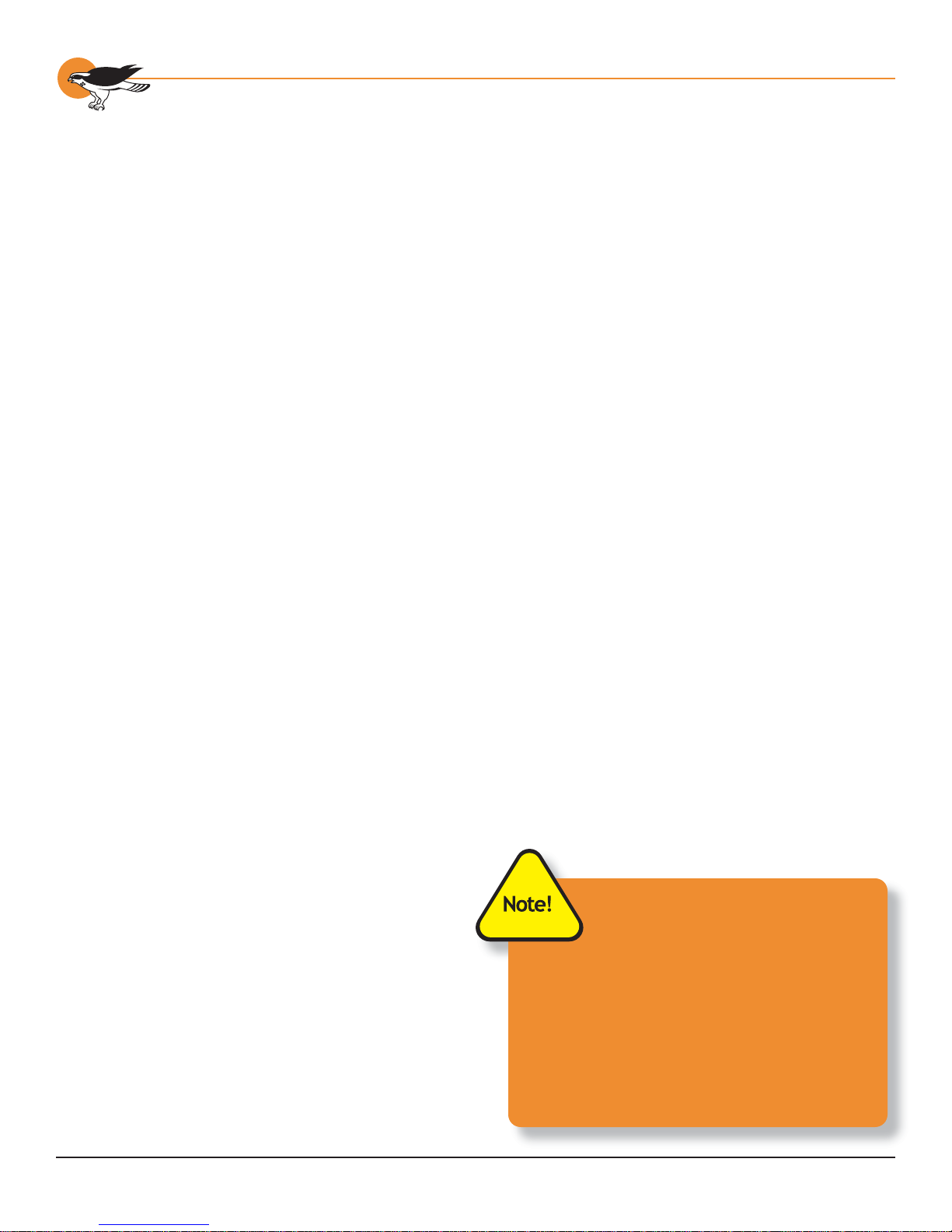
OSPREY-300 BACK PLATE
The Osprey-300 is assembled with a back plate
for standard systems (figure 1).
If you are not familia r with ho w to
install a PCI bus c ard, ref er t o y o ur
system’s documentation for more
complete, step-by-step instructions.
Y ou shou ld install the Ospre y-300 card
before insta lling the software driver.
Howev e r, with Windows XP yo u a lso h ave
the option to pre-i nsta ll the software
before insta l ling the hardware. analog
inputs only.
OSPREY-300 INPUT BREAKOUT CABLE
The Osprey-300 card is shipped with a breakout
cable (figure 2). The breakout connector has
inputs for composite video , S-Video , balanced
and unbalanced audio, and professional digital
audio. The breakout cable has a set (L/R) of
unbalanced RCA style audio connectors and a
set (L/R) of balanced (XLR) audio connectors.
Additionally, the right XLR balanced input also is
used as the professional digital audio input.
The Osprey-300 Back Plate
1
The input breakout cable is ViewCast Part
Number 34-05009-0 1.
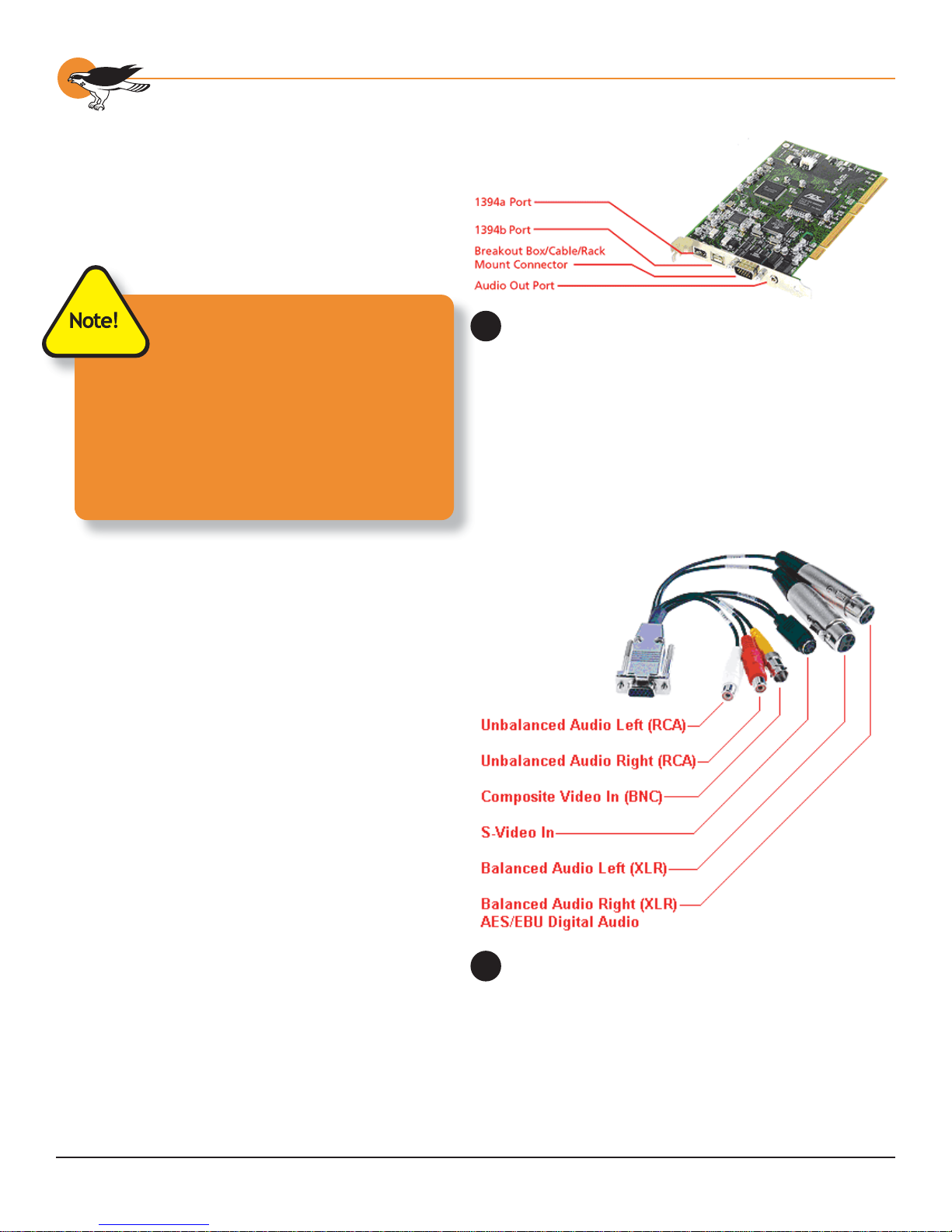
OSPREY-300 INPUT RACKMOUNT P AN EL
(
OPTIONAL)
A rackmount version of the breakout box is also
available (figure 3). The 1 unit high rack mount
input box has the same inputs as the break out
box but includes two sets of inputs. Thus a single
rackmount input unit provides for two Osprey300 cards. The rackmount unit is pictured above.
The rackmount breakout bo x is ViewCast Part
Number 95-00151-02. Exact connector layouts
are subject to change.
12
The Osprey-300 Input Breakout Cable
2
The Osprey-300 Input Rack-Mount Panel
3
Chapter 2: Hardware Overview
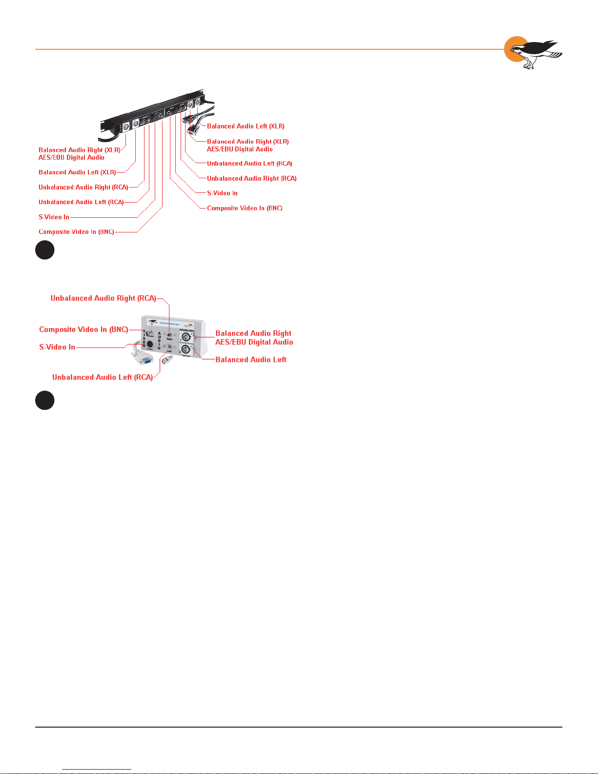
OSPREY-300 INPUT BREAKOUT BOX
(
OPTIONAL)
The breakout box has inputs for composite
video, S- Video , bala nced and unbalanced audio,
and professional digital audio. The breakout
cable/box has a set ( L/R) of unbalanced RCA
style audio connectors and a set (L/R) of
balanced (XLR) audio connectors. Additionally,
the right XLR balanced input also is used as the
professional digital audio input for the Osprey500 PRO and Osprey-500 DV PR O.
The input breakout box is ViewCast Part Number
95-00157-01.
CONNECTING A COMPOSITE SOURCE
Osprey-300 Inp u t Breakou t Box
4
If your video source provides only composite
video, connect the source’s output cable to the
Composite Video In connector.
Connecti ng a n S-Video Source
If your video source supports S-Video, connect
the source’s output cable to the S-Video In
connector. Compared to composite signals, SVideo provides a sharper image with better color
separation. S-Video uses a four-pin mini-DIN
connector that provides separate Y (luminance)
and C (chrominance) signals. Refer to Chapter
6 - Osprey-300 Video Control Dialog for
instructions on configuring the driver for S-Video.
Connecti ng an I E E E 139 4/DV Source
The Osprey-300 has two DV inputs, 1394a and
1394b. D V carries digital audio and video and
both can be independently used by the Osprey-
300. The DV inputs include a 9-pin for 1394b,
and 6-pin for 1394a connections.
13

Osprey - 3 00 User ’ s Gui de
GUIDELINES FOR CONNECTING FIREWIRE
D
EVICES
FireWire devices can be connected in any
combination of branching and chaining . There
are no SCSI-style ID numbers to set and no
termination requirements. The Osprey 300’ s
6-pin FireWire port can support up to 16
consecutive cable hops of 4.5 meters (14.76 feet)
each.
The Osprey 300’ s nine-pin FireWire 800 port
allows the use of various types of cabling
designed for 1394b operation of speeds up to
800 megabits per second. Selection of the proper
interconnect cables allows hop lengths of up to
100 meters.
FireWire 800 / 1394b devices connected to the
Osprey 300 9-pin port communicate over long
connections directly; no hub is required to gain
this added distance benefit in a pure FireWire
800 /1394b connection.
If you need to connect older FireWire devices at
a greater distance than the devices can support
directly, use a Fire Wire800 hub device connected
to the Osprey 300’s 9-pin port. FireWire 800
/1 394b hubs mak e it possible to connect older
FireWire 400 / 1394a devices up to 100 meters
apart. Neither the computer nor the remote
devices need to support FireWire 800 / 1394b
since the selected FireWire 800 /1394b hub and
its associated cables work with FireWire 400 /
1394a devices.
The Osprey 300 is designed to allow the
FireWire network to continue operating even if
the computer is shut down. Loss of power to the
computer will not affect the interoperation of
other devices on the same Fire Wire bus as long
as they are self-powered (i.e., do not require
power from the host PC ).
Pow e rering FireWi re devices via the Osp rey
300’s FireWire ports
The Osprey 300’s two FireWire (1394) ports are
capable of supplying power to certain FireWire
devices designed to receive DC power from the
host PC. There are two options available:
14

Chapter 2: Hardware Overview
• If the total DC power requirement for the
connected devices is 9 watts or less (at 12
VDC) the on-board DC power connector
does not need to be connected to a power
source.
• If the total load exceeds 9 watts, connect
a compatible power source to the DC
power connector at the rear of the Osprey
300 card, as shown below. Typically a DC
power connector from the PC’s internal
power supply of the type normally used to
supply power to a floppy disk drive may
be connected here without modification.
When this method is used the FireWire ports can
supply up to 30 watts of power.
ABOUT 1394 CONNECTORS
All 1394 devices are connected via one of three
connectors specified in the 1 3 94 standards.
• The original 4-pin connector is found on
most consumer Digital Video (DV) devices
such as camcorders. This connector
supports 1 3 94a communication but
does not support later changes to 1394
standards that allo w attached devices to
be powered by the bus.
• The 6-pin connector was introduced to
add the option to power the connected
device via the 1394 bus.
• The 9-pin connector was introduced to
support the bus speeds of FireWire800
and to support enhanced device
identification and control protocol. The
9-pin connector is described as Bi-Lingual
since you are allowed to connect any 1394
device via the appropriate adapter cable.
Cables with appropriate combinations of all of
these connectors are available from most AV
equipment retailers and electronics.
15
Osprey - 3 00 User ’ s Gui de
CONNECTING ANALOG AUDIO WITH THE
O
SPREY-300
The Osprey-300 audio connectors are made for
line level audio stereo equipment, such as VCR or
DVD outputs and can also take headphone level
outputs when the volume is adjusted midwa y
between high and low settings. It should be
noted that if you are using a camcorder or VCR
with only a single audio output, the volume
needs a slight adjustment.
Although the Osprey-300 accepts line level
inputs, the standard microphone shipped with
most soundcards is not compatible. You need to
use a powered microphone using connectors with
1-volt pea k-to-peak output.
RCA-style connectors for left and right line-level
audio are used on the Osprey-300.
The selection of audio input to capture is
independent of the video input selection.
The Osprey-300 breakout cable
includes thr ee au dio i nputs and
one audio output. You should
The Osprey-300 breakout cable
not connect an audio source
includes thr ee au dio i nputs and
simultaneous l y t o a ll three
one audio output. You should not
connect an audio source simultaneousl y
stereo 3 .5 mm cable or an RCA-style audio
to all three connections. Either connect a
cable to the input/output.
stereo 3 .5 mm cable or an RCA-style audio
connections. Ei ther c onnect a
cable to the input/output.
16

Ospre y -300 Capt ur e Ca r d
Insta l l ing the Softw ar e
f or W i ndo w s XP
CHAPTER
3
The CD which comes packaged with
the Osp rey-300 Capture Card contai n s
software compatible with Windows XP.
After you’ve installed the software, y ou can
test the card and software by running the
included application program, S wiftCap.
• Installing From the CD
• Downloading and Installing Updated
Drivers
• Installation Scenario 1: Osprey
Card(s) not Physically Installed in
the PC
• Installation Scenario 2: Osprey
Card(s) Physically Installed, but
Osprey Software not Installed
• T esting the Installation
• Uninstalling the Software
17
Osprey - 3 00 User ’ s Gui de
INSTALLING FROM THE CD
Insert the Osprey CD into your CDROM drive.
The installation instructions assume this is the
“D:” drive. Substitute the proper drive name as it
appears on your system where appropriate.
To run the install a t i on p rogram:
1. Click the Start button.
2. Click Run....
3. Enter d: \winxp\setup.ex e in the dialog box.
4. Click OK.
DOWNLOADING AND INSTALLING
U
PDA TED DRIVERS
The latest software drivers for Osprey Capture
Cards are available via FTP (file transfer
protocol), at the following location:
ftp://ftp.viewcast.com/pub/OSP-300/winXP/latest
There are also links to the drivers from our web
site, http://www.viewcast .com/
To download an updated driver:
1. Use your web browser , such as
Microsoft Internet Explorer or Netscape
Navigator, to fi nd our FTP site.
2. Download the web package fi le in
...winXP/latest to your hard disk.
3. Run the web package program.
To run the web package pr ogram:
1. Click the Start button.
2. Click Run.
3. Enter <pathname> in the dialog box,
where <pathname> is the location and
name of the fi le that you have downloaded.
4. Click OK. The program prompts
you for a temporary location to
unpack the install fi les to.
5. Select an apprpriate location and click OK.
These fi les are not to be
automatica l l y deleted after setup
has run. This is so that y o u ca n
perform the manual Pl ug and Play instal l i f
you want to. So make a note of where these
fi les are located, a nd de l ete them a fter the
install if y ou w an t t o c onserve disk spac e.
analog inputs only.
18

Chapter 3: Installing the Software for Windows XP
TWO INSTALLATION SCENARIOS
There are two main situations that might apply
to you:
• Scenario 1: Osprey Card( s) not Physically
Installed in the PC
• Scenario 2: Osprey Card(s) Physically
Installed, but Osprey Software not
Installed
In all cases, the most efficient and complete
installation method is to run the setup.exe
program on the product CD or in the web
package that you downloaded. The setup
program automates the Plug and Play steps
required to install the drivers and ensures that
they are performed correctly. It also installs the
bundled applets and User’s Guide. I f you have
multiple Osprey capture cards in the system it
configures all of the boards at the same time.
You can skip the detailed instructions if you are
upgrading from one Osprey driver version to
another . Just run the setup.exe file, and all the
updated components will be installed.
Scenario 1: Osprey Card(s) not P hysically
Installed in the PC
This is the method that we recommend if you
are installing an Osprey card for the first time
on a system, and the Osprey software has not
yet been installed. This scenario is called the
“Preinstall Scenario” . After the install is run ,
as soon as an Osprey card is installed in the
PC, it is detected and its drivers are started
automatically.
To preinsta ll the Ospre y drivers:
1. Using Windows Explorer, locate and
access the CD-ROM drive containing
the Osprey Installation CD-ROM .
2. Navigate to the WINXP directory .
3. Double-click SETUP.EXE. The Osprey
Capture Driver window displays.
4. Click Next. The Software License
Agreement window displays.
19
Osprey - 3 00 User ’ s Gui de
5. Click Yes to accept the End User
Software Agreement. If you do not
wish to accept the agreement, click No
to terminate the installation routine.
The Information window displays.
6. Click Next. The Osprey- 300
Driver window appears.
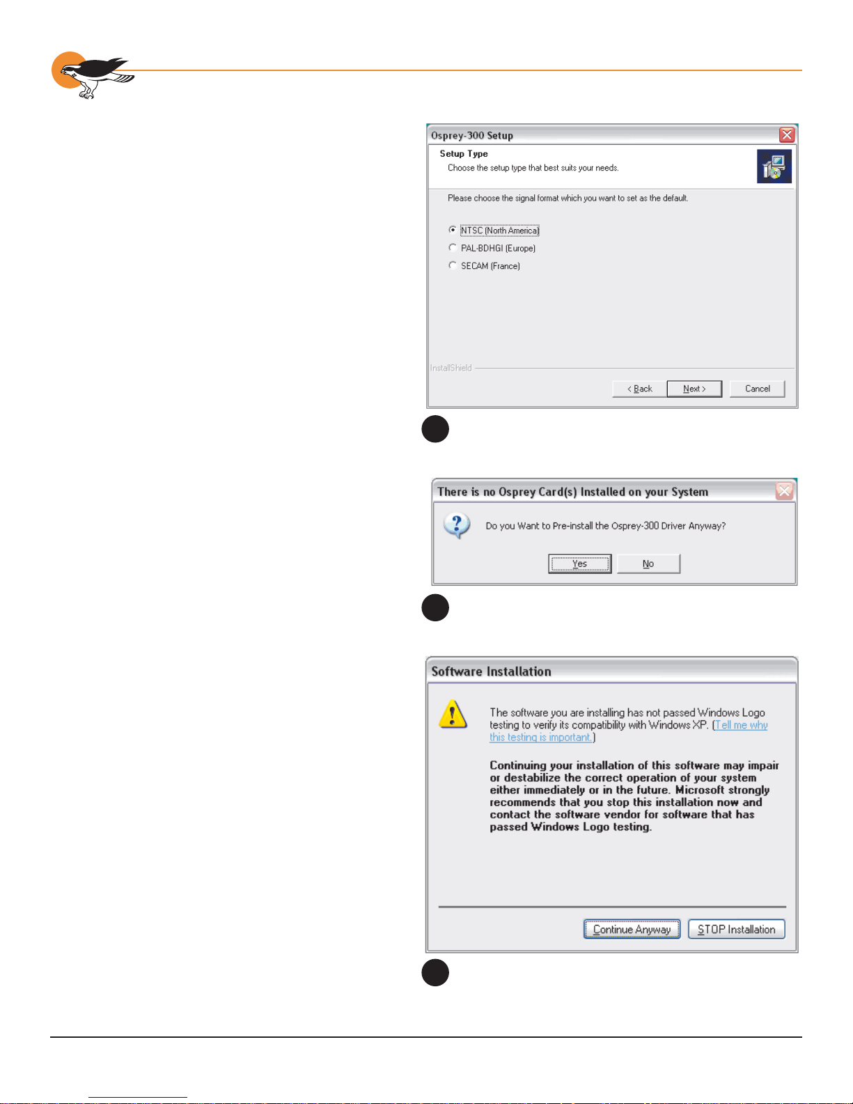
7. Click the radio button to select
the default signal format (fi gure
1 ). See Video Standard for more
information about signal formats.
8. Click Next. The Choose Destination
Location window displays.
9. If you wish to change the destination
location for the fi les, click Browse.
10 . Click Next. The Start Copying
Files window displays.
11 . Click Next. The Pre-installation
question window displays (fi gure 2).
12. Click Yes. The Software Installation
window displays (fi gure 3 ).
13. Click Continue Anyway. (This window will
only be displayed on drivers that have
not been WHQL Certifi ed; WHQL Certifi ed
drivers will skip this step). The fi les begin
copying to the computer. The ViewCast
Corporation/Osprey Video Division Special
Offers Shortcut window displays.
14 . I f y ou would lik e a shortcut installed on
your desktop, click Yes and a shortcut
is created on the desktop. If not, click
No. Once you have made your choice,
an information window displays.
15. Click OK to continue the installation. The
AVStream User Manual window displays.
16. I f you w ould lik e to view the A VStream
User Manual, click Yes and an Acrobat
Reader window opens. If not, click No.
17. Once you have made your choice, click OK.
The Product Registration window displays.
18. I f you w ould lik e to register your
Osprey-300 Capture card, click Yes
and a browser window will open with
a registration page. If not, click No.
Once you have made your choice, the
Setup Complete window displays.
19. Click Finish to complete the installation.
The Osprey-300 Setup window
1
The Pre-installa tion question wi n d ow
2
20
The Software Installation window
3

Chapter 3: Installing the Software for Windows XP
Scenario 2: Osprey Card(s) P hysically
Instal led, but Ospr e y So ftw a re not Installed
A product registration link is also
avai lable on the Programs menu
or on the Osprey Video web site
(http://www.viewcast.com/).
When you start your computer
after physica lly installi ng the
Osprey hardware, the Found New
Hardwar e W izard runs upon detecting new
hardware. The sequence of windows a re
simila r to that in Appendix H - Adding/
Moving Boards in Wi n do ws 2000 and XP.
In this case you have two options:
• Option A: Run the Installation Program
(Recommended)
• Option B: Use the New Hardware Found
Wizard (Not Recommended)
Option A: Run the I n s ta llation P rogram
(Recommended)
When Windows XP is first started for the first
time after the Osprey card is installed, the
New Hardware Found wizard displays one or
more times. Cancel out of these wizards. After
Windows XP has finished starting, perform the
following steps.
To install the Osprey drivers:
1. Using Windows Explorer, locate and
access the CD-ROM drive containing
the Osprey Installation CD-ROM .
2. Navigate to the WINXP directory .
3. Double-click SETUP.EXE. The Osprey
Capture Driver window displays.
4. Click Next. The Software License
Agreement window displays.
5. Click Yes to accept the End User
Software Agreement. If you do not
wish to accept the agreement, click No
to terminate the installation routine.
The Information window displays.
6. Click Next. The Select Components
window displays.
7. Click the radio button to select the default
signal format. See Video Standard for
more information about signal formats.
8. Click Next. The Choose Destination
Location window displays.
9. If you wish to change the destination
location for the fi les, click Browse.
10 . Click Next. The Start Copying
Files window displays.
11 . Click Next. The Hardware
Installation window display s.
12. Click Continue Anyway. (This window
will only be displayed on drivers that
have not been WHQL Certifi ed; WHQL
Certifi ed drivers will skip this step). The
Hardware Installation window displays.
21

Osprey - 3 00 User ’ s Gui de
13. Click Continue Anyway. (This window
will only be displayed on drivers that
have not been WHQL Certifi ed; WHQL
Certifi ed drivers will skip this step). The
fi les begin copying to the computer.
The ViewCast Corporation/Osprey Video Division
Special Offers Shortcut window displays.
14 . I f y ou would lik e a shortcut installed on
your desktop, click Yes and a shortcut
is created on the desktop. If not, click
No. Once you have made your choice,
an information window displays.
15. Click Next. The AVStream User
Manual window displays
16. I f you w ould lik e to view the A VStream
User Manual, click Yes and an Acrobat
Reader window opens. If not, click No.
17. Once you have made your choice, click OK.
The Product Registration window displays.
18. I f you w ould lik e to register your
Osprey-300 Capture card, click Yes
and a browser window will open with
a registration page. If not, click No.
Once you have made your choice, the
Setup Complete window displays.
19. Click Finish to restart the computer.
You must restart your computer to complete the
installation. Do not attempt to use your Osprey
card until after restarting the system .
22
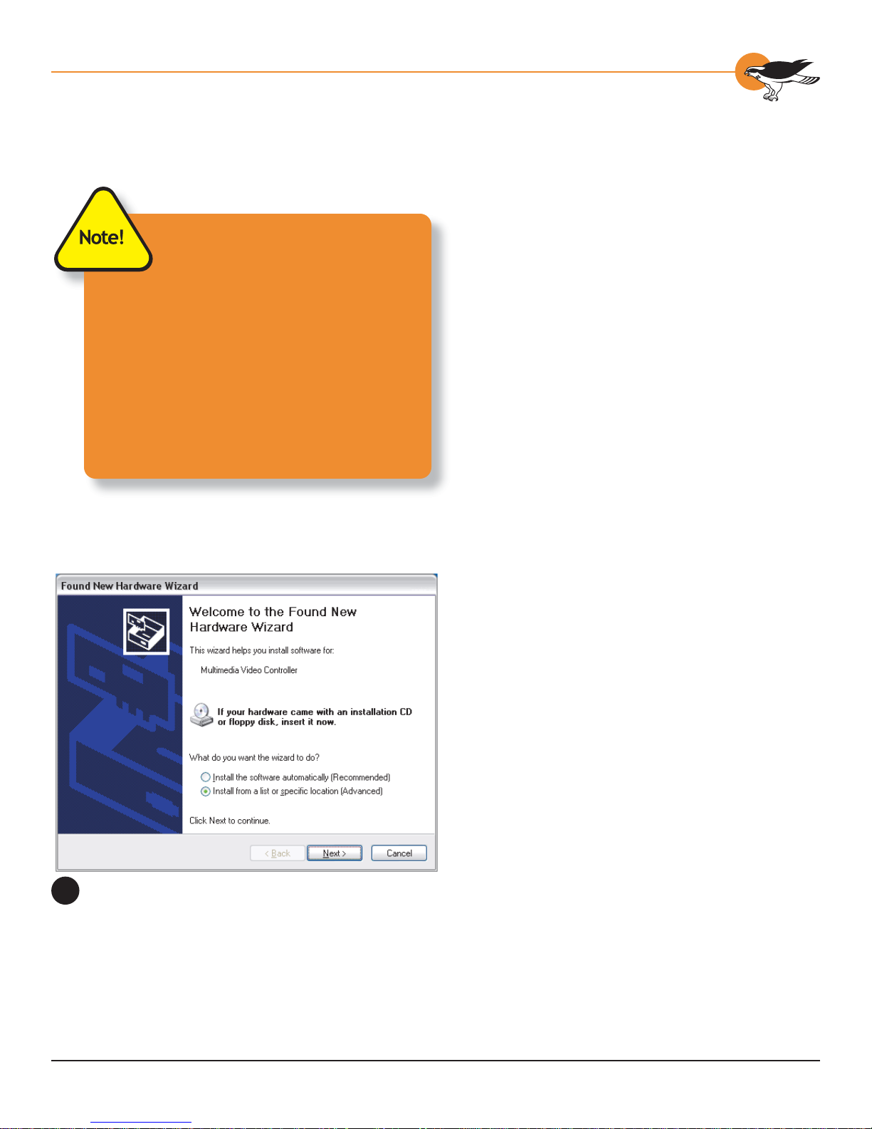
When Windows XP starts, it
detects the new card(s) and
starts the Found New Har dw are
wizard. When the Found New Hardware
Wizard de tects a devic e, please note the
terminology in the Wizard. It displays
either a Video Con t roller or an Audio
Controller.
The Found Ne w Hardwa re Wizard fi rst
detects one of the follo wing 2 de vic es:
“Osprey V ideo Capture Device”
“Osprey A u dio Cap t ure Device”
The Found New Hardware Wizard
4
window
Chapter 3: Installing the Software for Windows XP
Option B: Use the Ne w Ha rdware Found
Wizard (Not Recommended)
This method is more complicated than Option A.
It is particularly inconvenient if you are installing
multiple cards at once, since each card has to be
set up separa t el y.
When the Found New Hardware Wizard window
displays...
1. Click to select Install from a list or
specifi c location and click Next to
continue. The Found New Hardware
Wizard window appears (fi gure 4).
2. Click to select Search for the best
driver in these locations.
3. Click to select the checkbox Include this
location in the search, and type in the
drive letter of your CD-ROM drive followed
by “\WinXP” to provide the location of the
Windows XP driver on your distribution CD.
4. Click Next to continue. The “Please wait
while the wizard searches...” window
displays briefl y, and then is covered by
the Hardware Installation windo w.
5. Click Continue An yway. (This window
will only be displayed on drivers that
have not been WHQL Certifi ed; WHQL
Certifi ed drivers will skip this step).
The Setting System Restore Point
window displays briefl y, and then is
replaced by the Completing the Found
New H a rd w a re W i z a rd w i n do w.
6. Click Finish. Next the Wizard fi nds
and installs the audio portion of the
device. The Found New Hardware
Wizard window displays.
7. Click to select Install the software
automatically and click Next to continue.
The Hardware Installation window displays.
8. Click Continue An yway. (This window
will only be displayed on drivers
that have not been WHQL Certifi ed;
WHQL Certifi ed drivers will skip this
step). The Completing the Found New
Hardware Wi z ard w i n do w d i sp l a y s .
9. Click Finish.
If you are installing a single Osprey card, you
do not need to restart the computer. If y ou are
installing more than one Osprey card, you are
required to restart the computer.
23

Osprey - 3 00 User ’ s Gui de
After completing the Found New Hardware
Wizard, the applications for the Osprey driver
must also be installed. To do this, navigate to the
directory containing the Windows XP driver for
your Osprey card, and run SETUP.EXE.
For detailed steps , please refer to Option A: Run
the Installation Program ( Recommended).
TESTING THE INSTALLATION
1. Veri fy th e h a rdware in sta l l at i on
is compl ete , in acco rda nce wi th
the directions in Chapter 2.
2. Connect a camera, VCR, or
other video signal source to the
Osprey card’ s con nectors.
3. Open the Osprey Capture
group in the Start menu.
4. Click the SwiftCap icon.
5. Verify the screen displays a still video
frame from the Osprey card. Click the
Preview button. The screen should
display moving video frames.
6. If the video area is a plain blue fi eld , it
could be for one of the following reasons:
• The driver is looking for video on the
wrong input connector. You can either
move the video cable to another
connector, or reconfigure the driver using
its Control Dialog (refer to Chapter 6 Osprey-300 Video Control Dialog).
• The video source is not turned on or
activated.
7. If the video area is scrambled or has bad
color , the signal format of your video
source may be different from the signal
format selected in the driver software.
Since the driver defaults to NTSC-M signal
format, users of PAL and SECAM equipment
always need to change the driver’s signal
format the fi rst time they run the driver .
Please see Video Standard in Chapter
6 – Osprey-300 Video Control Dialog.
24

Chapter 3: Installing the Software for Windows XP
UNINSTALLING THE SOFTWARE
If you ever need to remove the Osprey driver
from your system, proceed as follows:
1. Open the Control Panel.
2. Double-click Add/Remove Programs.
3. Click to select Change or
Remove Programs.
4. Highlight the Osprey Capture Driver entry.
5. Click Change/Remove in the Osprey
entry. The un instal l progra m begi ns.
6. Click Yes to proceed.
7. Click OK when the process is complete.
8. Reboot y ou r com put er to comp lete
the uninstall process.
CONFIGURING THE VIDEO CAPTURE
D
RIVER
Use the video capture application SwiftCap to
access the Osprey driver properties described in
Chapter 5 - Analog Video Driver Properties.
SwiftCap is included with the Osprey package.
It is useful for testing the installation and for
general purpose viewing of video. Refer to
Chapter 8 for instructions on using this applet.
CONFIGURING FIREWIRE DRIVERS FOR
W
INDOWS XP
Windows XP will typically install the FireWire
drivers as a “Texas Instruments OHCI Compliant
IEEE 1394 Host Controller”. Successful
installation can be verified in the Windows
Device Manager (see figure 1 in Chapter 4).
25
Ospre y -300 Capt ur e Ca r d
Digi ta l V i deo on t he
Ospr ey -3 00
CHAPTER
4
The Osprey-300 IEEE 13 94 inputs connect
to standard Microsoft drivers rather
than to the Osprey AVStream driver.
Osprey customers who are familiar with
the Osprey-500, -540, and -560 should
understand that the DV implementation
is completely different. On the Osprey5XX cards, the D V connector and capture
hardware sit behind the Osprey audio and
video capture devices and are controlled by
the Osprey driver. On the Osprey- 300, the
DV is an entirely independent device.
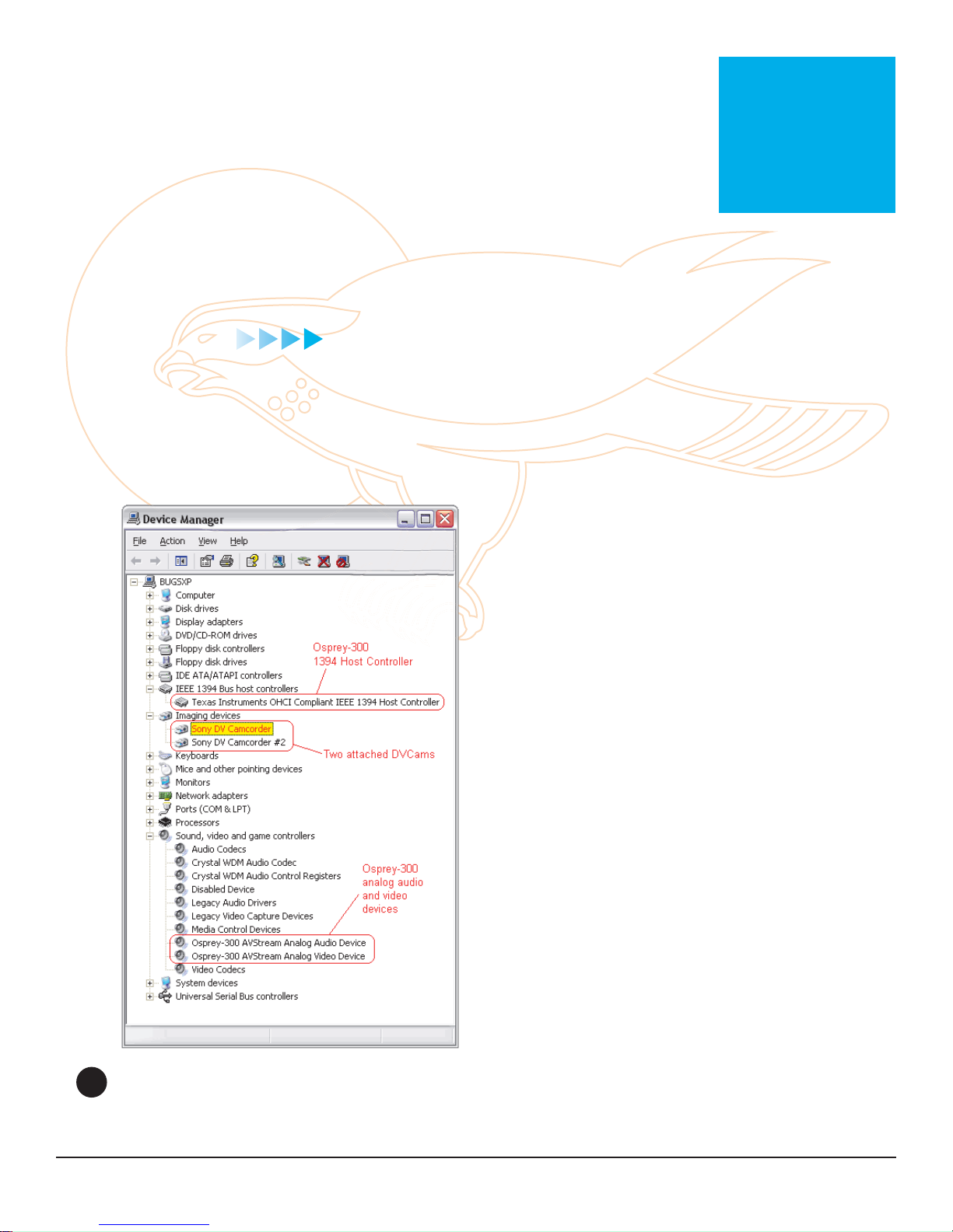
The Windows XP Device Manager
1
If you look at the Windows XP Device
Manager (figure 1) after installing an
Osprey-300 you will see something like
this. Under the category “I EEE 1394 Bus
host controllers” there wil l be a n entry for
the Texas Instruments controller on the
Osprey-300. This device is automatically
activated whenever the card is plugged
into the system. If you plug a DVCam into
the Osprey card, an entry for it will appear
under the “Imaging devices” heading.
Both the 1394 controller and an y devices
plugged into it are logically distinct from
the Osprey-300 analog audio and video
devices shown under Sound, video and
game controllers.
27

Osprey - 3 00 User ’ s Gui de
In theory you should be able to connect any
1394 device to the card, not just a digital video
(DV) source. In this chapter, however, we focus
on using the 1394 connector with DV devices
such as camcorders.
Most major multimedia applications will
recognize DV devices and work with them fully.
For example, we have verified that Windows
Media Encoder 9 supports a DVCam attached
to an Osprey-300. With ma jor applications
the DV connection should “just work” and the
information here is for background and reference
only.
SPECIFICS OF DV CAPTURE
The DirectShow filter used for DV capture is
called the “Microsoft DV Camera and VCR”. This
filter can capture video only, or audio and video
together. I n this respect it is different from the
Osprey analog capture driver, which has logically
distinct modules for audio and video capture.
Unlike the Osprey analog driver, which captures
video into many user-selectable sizes and
formats, the DV capture filter delivers just one
format for each video standard.
For 525-line (NTSC) video, the video size is
720x480 and the video rate is 29.97 frames per
second.
For 625-line (PAL/SECAM) video, the video size
is 720x576 and the video rate is 25 frames per
second.
The video format is always a compressed format
designated w ith th e fo u r-character identifier
“dvsd” (case-sensitive, and lower case). In this
format, one NTSC video frame is 12 0,000 b ytes,
and one PAL./SECAM video frame is 144,000
bytes. By comparison, one uncompressed
YUY2 NTSC frame, requiring 2 bytes per pixel ,
is 691,200 bytes, and one uncompressed YUY2
half-siz ed frame (360x240) is 172,800 bytes;
that is to say, the half-sized YUY2 frame is
significantly larger than the full -s iz ed dv sd frame.
28

Chapter 4: Digital Video on the Osprey-3 00
The dvsd format comes in two flavors - videoonly, and audio + video interleaved. The audio
+ video data rate is slightly higher than the
120,000 or 144,000 bytes per frame quoted
above - for NTSC it is about 129, 000 bytes per
frame, or about 3,866,130 bytes per second.
The dvsd format can be captured directly to
AVI files. There are two subformats - Type 1
and Type 2. The Type 1 format stores the audio
+ video data as a single stream. The Type 2
format stores the audio and video data as two
separate streams. The Type 1 format is more
compact and efficient but is not backwardcompatible with Video for Windows. Osprey’s
SwiftCap application, as described below,
currently supports only the Type 1 format. With
other suitable applications the Osprey-300 D V
conne cto r can cap t ure in e ither fo rmat.
Several additional DirectShow filters support the
DV capture module.
The most important is the DV Video Decoder.
This filter accepts dvsd video-only streams as
input. As output it delivers an uncompressed
YUY2 stream at full, half, 1/4 , or 1/8 si z e. This
filter is alw ays used when rendering v i d eo.
When capturing video without compression, it
is normally not used, but could be useful for
capturing quarter-sized or 1/8-sized video, at
some savings in data rate. (Note that the fulland half-size options would increase the data
rate to no purpose.) When video is captured
with compression , a D V Video Decoder will be
placed in front of the compressor, to deliver the
YUY2 input that the compressor uses.
The other specializ ed DV filter commonly used
in capture is the DV splitter, which accepts a
dvsd audio + video interleaved stream as input,
and outputs dvsd video-only on one pin , and
standard uncompressed audio on the other.
Following the how-to description of SwiftCap,
there are some sample DirectShow graphs that
show some of the ways these components can be
connected together.
29
Osprey - 3 00 User ’ s Gui de
SWIFTCAP
This section provides specific information about
how the bundled capture application SwiftCap
supports DV capture on the Osprey- 300 . Note that
this manual also contains a more complete general
reference section on SwiftCap that is oriented
towards its support of the Osprey analog driver.
Note - only more recent versions of SwiftCap work
with DV devices. The “Help -> About SwiftCap”
message should show a version number 3.1. 1.0
or later, and be copyrighted 2004 or later. The
SwiftCap version supplied with the Osprey-300 driver
package is 3.1.1.0.
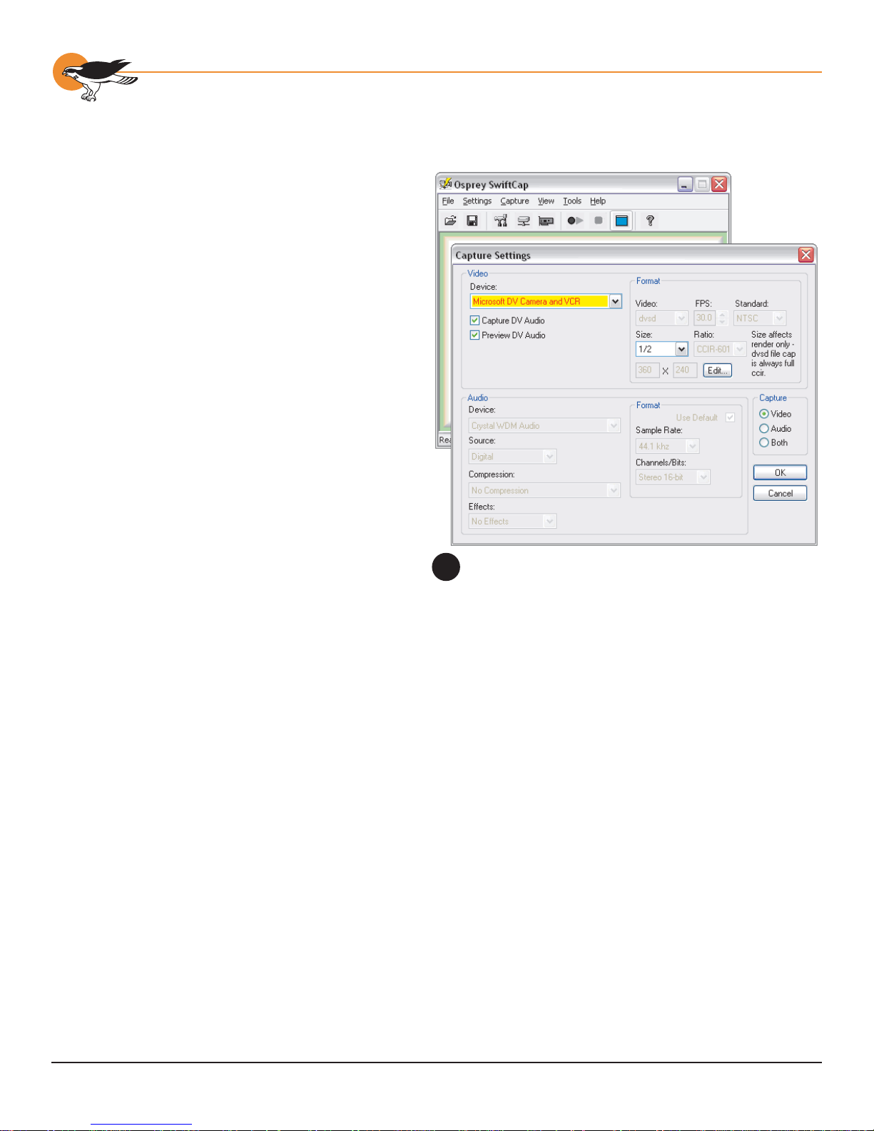
The main features of SwiftCap’s DV support are
highlighted in figure 2.
If a device such as a DV camcorder is connected to
the Osprey-300, it will appear in the video device list
as a “Microsoft DV Camera and VCR”. The Capture
Settings dialog will appear as shown only when a
DV device is selected ; for analog vidcap devices the
dialog is set u p d i fferently.
SwiftCap’s Digital Video Capture Options
2
Note that even though a DVCam is an audio + video
device, DirectShow classifies and enumerates it as
a video device only . S wiftCap adheres to this logic
by displaying a DVCam as a video device choice, but not as an audio device choice. If you want to capture
both audio and video from a DVCam, you should select “Video” in the Capture group at the right. If you
want to capture DV video, and audio from another analog source, select “Capture Both” and uncheck
“Capture DV Audio” (You can even work to capture both DV audio and analog audio at the same time).
If you select “Preview DV Audio”, S wiftCap will preview audio both in preview-only mode and when capture
is happening. (SwiftCap does not preview audio with analog capture devices.) This capability could be
useful when capturing audio from a remote or recorded source - but you will want to turn it off for capture
from a live source , to a void feedback.
Two checkboxes in the Video group, “Capture DV Audio” and “Preview DV Audio,” control DV audio.
The video Size control affects size of previewed video only, not captured video. As previously explained,
dvsd video from the D V Video Capture Filter is always full sized and in CCIR-601 format, that is, 720x480
NTSC or 720x576 P AL/SECAM. While a DV Video Decoder Filter could be used to downsize the video,
SwiftCap does not currently support this. SwiftCap also does not support compression of DV video at this
time.
As you can see, the rest of the Video Format controls are greyed and read-only. The video format from a
DVCam is always “dvsd”, as described above. SwiftCap will determine for you whether the camera is NTSC
and 30 frames per second, or PAL and 25 frames per second. The aspect ratio from DVCams is alwa ys
CCIR-601, meaning that the pixel width is 720 .
30
Chapter 4: Digital Video on the Osprey-3 00
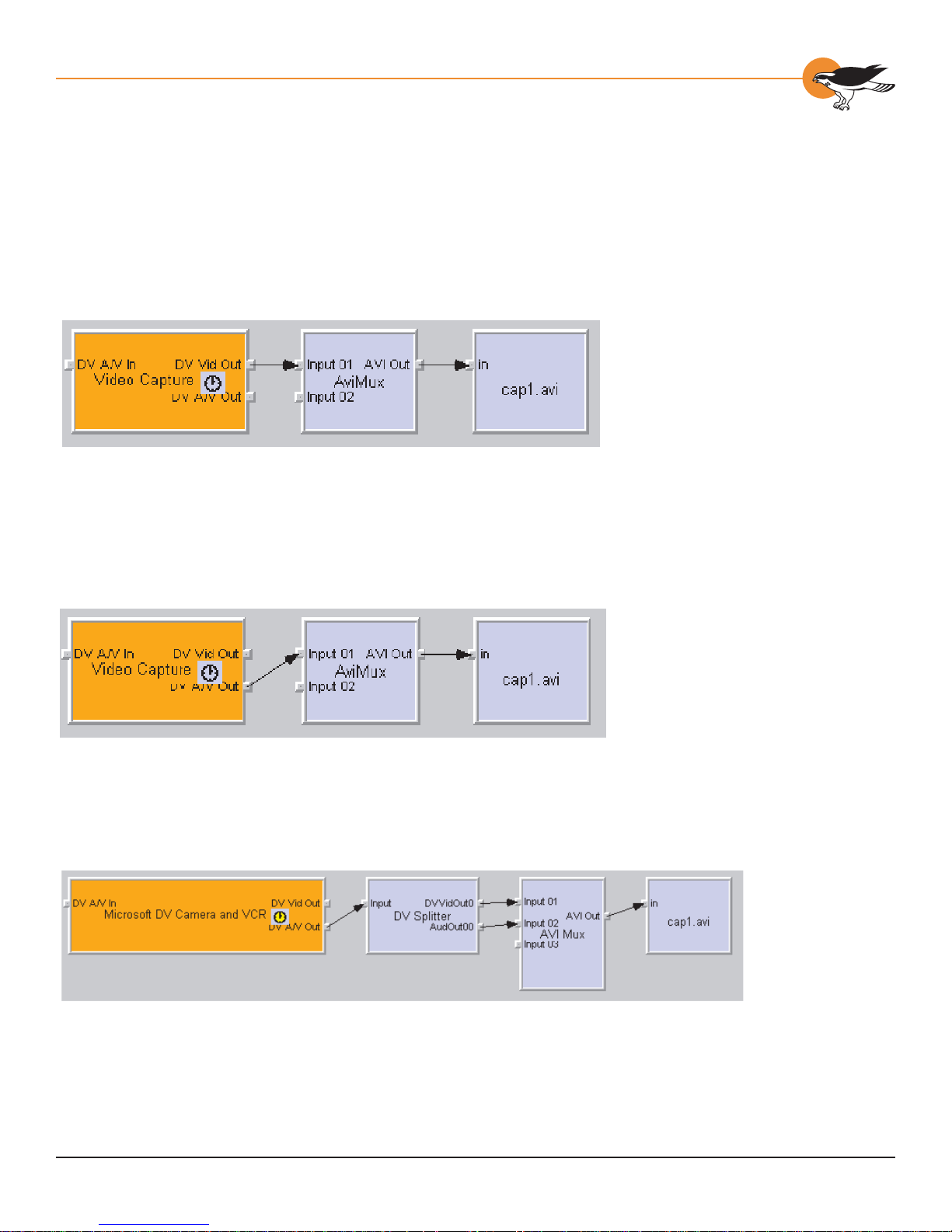
GRAPHS
This section contains more technical information that may give some users helpful insight into DV capture
and rendering operations. The illustrations are DirectShow graphs as displayed by GraphEdit.
For still more advanced information, refer to the DirectX 9 SDK documentation available from Microsoft.
This graph shows the simplest possible video-only DV capture graph.
This is the simplest possible audio + video DV capture graph. The difference is that the DV Capture Filter’ s
A/V Out pin is used, which delivers an interleaved A/V stream rather than a pure video stream. The AVI file
will be “Type 1” - that is, the audio + video will be structured as a single stream; this format is efficient but
is DirectShow-only, not backwards-compatible to Video for Windows.
This is the simplest possible audio + video “Type 2” graph. The AVI file, now Video for Windows compatible,
is now structured as an “auds” stream plus a “vids” stream. The DV Splitter Filter splits the interleaved A/V
stream in to a dvsd video stream plus a PCM audio stream.
31

Osprey - 3 00 User ’ s Gui de
This graph shows basic video-only rendering. The DV Video Decoder converts the “dvsd” DV video stream
to the YUY2 format required by the video renderer. The Smart Tee allows a capture stream to be connected
as well as the preview stream. It is optional in this particular graph; however, the normal graph-building
process usually inserts a SmartT ee automatically.
This graph renders both audio and video. The Capture Filter’s D V A/V Out pin is used instead of the videoonly pin. A DV Splitter is added to the graph to split the interleaved A/V stream into separate audio and
video. The audio stream is standard PCM audio which can be directly rendered by a standard rendering
filter. The video stream is in dvsd format and as before is converted to YUY2 by the DV Video Decoder
before re ndering.
This graph combines video capture with video preview rendering. Here the Smart Tee becomes mandatory
to split the single video stream into two.
32

Chapter 4: Digital Video on the Osprey-3 00
Audio and video, capture with preview. This is the most complex graph that S wiftCap currently supports.
It is a combination of elements described in the previous graphs.
This graph (which SwiftCap currently does not support)
shows an A/V capture-only configuration to which a DV
Video Decoder Filter has been added. The properties page
also shown (at left) belongs to the DV Video Decoder and
can be accessed directly from GraphEdit and some other
applications. This graph captures the video stream in YUY2
format. As explained previously, the dvsd native D V format
is a compressed format, whereas YUY2 is not. A YUY2
stream at 720x480 is much larger than the dvsd version,
and the YUY2 stream at 360x240 is somewhat larger; you
would probably want to use this graph only for 1/4 or 1/8
size capture.
33

Osprey - 3 00 User ’ s Gui de
This graph shows audio + video capture with the Microsoft Video 1 compressor. The compressor requires
YUY2 as its input fomat and so the DV Video Decoder precedes it. A compressed graph of this kind
substantially compresses the AVI data, at the expense of cpu time and video quality .
34

Ospre y -300 Capt ur e Ca r d
Ana l og V i deo Driv e r
Properties
CHAPTER
5
A common filtergraph based on the
1
Osprey AVStream driver, with a preview
window.
FILTERS, PINS, FILTERGRAPHS, AND
P
ROPERTIES
In DirectShow the words “Filter” and “Pin”
are frequently used.
A “Filter” is a component that performs
a processing step on an audio or video
(or closed caption, or VBI…) stream. A
video capture device such as the Osprey
AVStream driver is a filter that has
associated hardware. Other types of
filters such as compressors, mixers, and
renderers are software-only – they have
no associated hardware.
A filter has input and/or output “Pins”
where multimedia streams enter and exit.
A “FilterGraph ” is a set of filters connected
together with their pins. All DirectShow
applications create an implied, invisible
filtergraph to carry out their functions.
The GraphEdit developers’ application
takes this a step further by showing the
organization of the filtergraph visually
(figure 1).
35

Osprey - 3 00 User ’ s Gui de
Both filters and pins may hav e associated
“Properties”. Properties are control parameters
that can be read from or written to the
component. As a user, you interact with them
as visual “Property Sheets”, or “Property Pages”,
or “T abs” that are part of a tabbed dialog. If
you are a programmer, you might set properties
directly from the code of your application.
The block labeled “Osprey-300 Device 1” in the
center of the filtergraph is the Osprey capture
filter, and the “Filter Properties” about to be
described are the properties and controls for
that component. On the o300avs cap filter there
are four pins. Two of these pins, Capture and
Preview , ha v e associated user-settable properties
that are described below in the section entitled
“Pin Properties”.
The block labeled “Osprey Crossbar” performs
input selection for the driver. The main Osprey
capture filter has an “I nput” property sheet that
performs the same input selection function.
OSPREY VIDEO CAPTURE DEVICE
P
ROPERTIES
Selecting t h e Device
If you have multiple audio/video capture devices
installed, the Filter Properties are organized on
a per-device basis. The Filter Properties that are
displayed are for the currently selected device.
Windows Med i a Encoder 9:
• In the View menu, select Properties Panel.
• Make sure that under Source from:, the
Devices radio button is selected.
• Check Video: Select the device you want
from the Video: drop box.
• Check Audio: Select the audio device you
want from the Audio drop box.
Helix P roducer Pl us:
• Click the Devices radio button at the left
of the main window.
• Select the desired devices using the drop
boxes on the left half of the main window
labeled “Audio:” and “Video:”.
36

Chapter 5: Analog Video Driver Properties
SwiftCap:
• Pull down the Capture menu, select
Settings…
• Select the device from the drop list in the
upper left corner of the Capture Settings
dialog box.
• Real Producer 8, VidCap32, and other
Video for Windows applications:
• Refer to Using the Osprey AVStream
Driver with Video for Windows
Applications, below.
ACCESSING THE PROPERTY PAGES
F rom Windows Med i a Encoder 9:
1. In the View menu, select Properties Panel.
2. Click the Confi gure… button to the
right of the video device name.
The Video Properties Toolbar icon in
2
SwiftCap.
You can select the input to the device directly
from the ensuing dialog. For other device
settings, click the Video Properties button.
F rom Helix P roducer Pl us:
• For audio, click “Settings” to the right of
the “Audio :” drop box, and select “VendorProvided Controls” from the drop list.
• For video, click “Settings” to the right
of the “Video:” drop bo x . Select
“DirectShow Filter Video Capture” from
the drop list to set up the Osprey device.
Select “DirectShow Pin” to set up the
capture pin on the Osprey device.
Set up “DirectShow Filter Video Capture” the way
you want it before you set up the capture pin.
F rom SwiftCap:
Click the Video Properties toolbar icon (figure 2).
F rom Real Producer 8 , V i dCap32, and other
Video fo r W i n do w s app lication s:
Refer to Using the Osprey AVStream Driver with
Video for Windows Applications, below.
37

Osprey - 3 00 User ’ s Gui de
COMMON DIALOG FEATURES
The Properties are organized as tabs or pages
in a dialog box entitled o300avs cap Properties.
The tabs are as follows:
Note that these property tabs are not where you
set frame size and frame rate. These are part
of the “pin properties”, and are explained in Pin
Properties, below.
The tabs across the top of the Filter Properties
Dialog (figure 3) select the specific “tabs”, or
“property sheets”, or “pages” described below.
• Video Proc Amp: set brightness, contrast,
saturati o n, hue.
• Video Decoder: select the video standard
(NTSC, PAL, or SECAM).
• Input: select the video input and NTSC/
PAL/SECAM video standard.
• Device: miscellaneous , less frequently
used controls.
• RefSize: set the reference size for
cropping.
• Size and Crop: set output size, enable
cropping, set cropping rectangle.
• Logo: set up on-video logos.
• SimulStream: control the SimulStream
option.
Tabs located along the top of the video
3
properties dialog
On some systems y ou ma y see additional tabs
besides the six shown above. The additional tabs
are system-supplied, for-your - i nformation only,
and contain no controls that you can set.
• The OK button (figure 4) commits the
changes you have made on the currently
displayed page, and exits the dialog.
• The Cancel button exits the dialog without
committing the changes you hav e made
on the currently display ed page.
• Changes made before the most recent
click of the Apply button are not
cancelled.
• The Apply button commits the changes
you have made on the currently displayed
page, without exiting the dialog.
• The Help button accesses online help.
38
Action buttons located at the bottom of
4
the Properties Dialog

Chapter 5: Analog Video Driver Properties
Note that the OK and Apply buttons commit only
the changes on the currently displayed page. To
set changes on three different pages you w ould
have to click Apply twice and OK once.
THE VIDEO PROC AMP T AB
Use the four slider controls to set Brightness,
Contrast, Hue, and Saturation ( figure 5). If
preview video is running when you access
this page, you can see your adjustments
interactively.
The Hue adjustment does not function for PAL
video or when the DV ( 1394) input is selected.
The slider is disabled when any of these modes is
in effect.
The Video Proc Amp Tab
5
The Video Decoder Tab
6
The Brightness, Contrast, Hue, and Saturation
adjustments do not function when the Bypass
Color Correction box on the Input page is
checked. In this case the slider is disabled.
When you make a change to the video standard,
the input, or the Bypass Color Correction
control, the sliders on this page may not become
correctly enabled or disabled until the properties
dialog h as been closed a n d reopened.
Changes made on this page apply to all video
preview and capture pins on the currently
selected device.
THE VIDEO DECODER TAB
The VideoDecoder Tab (figure 6) is a DirectShow
standard control for setting the NTSC/PAL/
SECAM video standard. Note that these controls
are also on the Input Tab. Most users will find
the Input Tab more convenient to use. Refer to
the Input Tab description below, and to Video
Driver Topics, Video Standards and Sizes.
Changes apply to all video preview and capture
pins on the currently selected device. If you
have multiple Osprey cards, set the input
individually for each of them.
39

Osprey - 3 00 User ’ s Gui de
Changes made with this control take effect
immediately – the Apply button really has no
function on this tab. If video is running and a
standard is selected that does not match the
incoming signal, the video is likely to freeze or
glitch until the signal matches again.
THE INPUT TAB
The Video Input control ( figure 7) is a drop list
for selecting the video signal source. The inputs
shown on the list are tailored to the inputs
available on your hardware.
The Video Input control performs about the
same function as a crossbar filter attached to the
capture filter’s Analog Video In pin.
It has one additional control, however, the
Bypass Color Correction checkbox that is enabled
whenever a digital input is selected. When this
box is unchecked, video brightness , contrast, and
saturation can be adjusted using the controls on
the Video Proc Amp property page. When this
box is checked, these controls are bypassed and
the driver does not modify the color settings.
The Input Tab
7
The read-only button marked Video Present
shows whether the hardware is detecting a video
signal on the currently active input. This control
is updated only when you make a change to
the Video Input or Video Standard and click the
Apply button .
The Video Standard control group is the same
as the control on the Video Decoder tab. The
North American standard is NTSC. The Japanese
standard is NTSC-Japan. The five PAL standards ,
B, D , G, H, I are almost identical to each other,
and are treated the same wa y b y the Osprey
driver. The driver also supports SECAM video.
Refer to Video Driver Topics, Video Standards
and Sizes, for more information.
Changes made to these settings apply to all
video preview and capture pins on the currently
selected device. If y ou have multiple Osprey
cards, set the input individually for each of them.
40

Chapter 5: Analog Video Driver Properties
Changes take effect only when you click the
Apply button. If video is running, there may be a
brief glitch while the settings take effect.
THE DEVICE TAB
These controls (figure 8) set important low-level
operating parameters for the driver. Changes
made on this page apply to all video preview and
capture pins on the currently selected device.
Field Order
This control is useful only if you are capturing
video from a digital camera, routed through the
Osprey card’s analog composite or s- video input.
The normal field pairing order for NTSC cameras
is Odd-Even. However, some progressive video
cameras and video footage that originated on
film may have a different field dominance that
requires pairing of even/odd fields into frames.
If you notice that there are problems with
interlaced video such as “comb” effects , see if
the Even-Odd setting clears up the problem.
The Device Tab
8
Deinterlace
When you capture interlaced video that has high
motion content, you will see horizontal “comb”
artifacts that reduce the apparent quality .
Deinterlacing will remov e the comb effects and
produce a better looking high motion image.
Deinterlacing has little if any effect on still or
low motion images. The Osprey AVStream driver
uses two different deinterlace methods for
Capture and Preview. For Capture, a softwarebased deinterlacing function is used. Since the
deinterlacing is done in software, it does use CPU
bandwidth and thus may have a performance
impact on your video processing depending on
the speed of your machine.
41

Osprey - 3 00 User ’ s Gui de
For Preview, the driver exploits the hardwarebased deinterlacing capability that resides in
most display adapters. No CPU bandwidth is
used; however, our experience so far is that the
quality of the deinterlacing is not quite as high
as that offered by the software-based capture
pin method. When Preview Pin deinterlace is
enabled, the only video color formats available
for preview are YUY2 and RGB8 greyscale, since
hardware deinterlace only works only for YUY2.
The deinterlace controls have no effect when
captured video is from a single field only. Video
is captured only from a single field if the capture
height before cropping is less than or equal to
the field height.
For more information about interlacing and
deinterlacing, refer to De-Interlacing in the Video
Driver T opics chapter.
Transfer Mode
This control affects capture of video from a
digital camera, routed typically through the
Osprey card’s DV input. In normal video,
including many digital cameras, field 1 containing
lines 1, 3, 5… of the video is transmitted in its
entirety followed by field 2 containing lines 2 , 4,
6…. The capture card interleaves the two fields
together , and the In terleaved setting should be
used. A digital camera , ho w ever , may transfer
data in progressive mode, meaning that the data
is transferred as a single field of lines 1, 2, 3, 4,
5…. You will know that you need to use the Odd/
Even setting if the video displays as two separate
compressed fields, one on top of the other.
Horizontal De l ay
This control adjusts the left-right position of the
image. The horizontal delay from horizontal sync
to start of video is different from the standard
for some input devices. If this is a problem you
may see a vertical black line at the left or right
edge of the video.
42

Chapter 5: Analog Video Driver Properties
You can use this control to reposition the video.
If you start video preview running before you
use this control , repositioning will be interactive.
Use the arrow buttons to move the video, and
the “0” button to reset it to the normal position.
With uncropped video, the video will shift only on
every second increment 0, 2, 4 … . This control
affects all inputs on the currently selected
device.
PCI Compa t i bility Mode
Some PCI bridges present compatibility problems
for the Osprey hardware, especially systems
using the 430FX chipset. The symptom will be
dropping of a significant amount of audio and/or
video data. Use the “Normal” setting unless you
are seeing this symptom, but if you are seeing it,
try setting this control to “430FX”, or, possibly, to
“VIA/SYS”. The change will take effect as soon
as you click “Apply” or “OK”.
The Gamma Correction Control
9
Gamma Co rrection
The gamma correction control (figure 9) adjusts
the gamma curv e of capture and/or preview
video. The lumina or intensity component of
analog video is not linear. I t is bi ased (1) to
improve the effective bandwidth for transmitting
low intensity information , and (2) to match the
nonlinear response of a standard analog TV set.
For some digital or computer video applications,
the standard gamma curve is not correct, and
you may want to remove it partly or entirely.
To test this interface, run SwiftCap. Turn off
preview. Set the video capture source to YUY2
format. Set the video capture destination to
“Renderer” and select “Video Renderer”, not
VMR7 or VMR9. Start the renderer and open the
driver properties dialog to the Device page.
Note the following points:
1. This gamma control is separate from
the Gamma slider on the systemprovided Video Proc Amp property
page. That control will remain greyed
out even when the custom gamma
correction control is en abl ed .
2. Gamma correction works only on YUV
video formats, which include YUY2,
UYVY , I 420, YVU9 , and greyscale
(“Grey8” or “RGB8”). It does not
work on RGB32, RGB24, or RGB1 5.
43

Osprey - 3 00 User ’ s Gui de
3. Note also that gamma correction
will only show up in preview video if
“Ad just preview video” is checked.
4. The “Adjust preview video” checkbox
is provided because gamma correction
of preview video may be quite slow.
Gamma correction of video rendered
by the VMR7 renderer, even if on a
capture pin, may also be pretty slow.
The checkbox titled “Gamma Correction” at the
top of this control group turns gamma correction
on or off entirely. When gamma correction is
turned on, there wi ll be additional p rocessing
overhead to perform the correction in software.
Therefore, rather than setting gamma correction
to 1.0 – the neutral level – turn it off entirely
with this checkbox.
The large square has three components: The
bottom third shows the uncorrected video
intensity gradient. The upper two-thirds shows
the video intensity with the current gamma
setting applied. I f the current setting is 1.0, the
two portions will look identical. The red curve is
a graph of the correction factor. The horizontal
axis is the luminance level of the incoming
video; the vertical axis is the gamma-corrected
luminance level. When the gamma setting is 1.0
this curve is a straight line.
You can drag the mouse across the large square
to adjust the gamma factor. If you do this while
video is rendering as suggested above, you will
see the changes interactively. Drag the curve for
large adjustments. Use the edit box and buttons
for small adjustments.
The white edit box shows the current gamma
factor. When video luminance is on a scale from
0.0 to 1.0, the output video will be the input
video raised to the power of the gamma factor.
The plus [+] and minus [-] buttons linearly
adjust the gamma factor. The button marked
2.20 (when the video standard is NTSC) or 2.80
(when the standard is PAL or SECAM) sets the
gamma factor to the indicated value, which is
the default gamma correction removal factor for
that standard. That is, if the source camera is
gamma-biased exactly according to the standard,
this default value will exactly remove the gamma
bias, and the luminance of the video will be
exactly linear.
44

The Device Info Dialog
10
Chapter 5: Analog Video Driver Properties
SimulStream
The SimulStream group will say “Not installed for
this device” until you install either an evaluation
version or full version of SimulStream. When
SimulStream is installed it will indicate the status
of the license. Refer to the SimulStream section
of this guide for a description.
Device Info
Device Info displays basic information (figure 10)
about an Osprey device – what model it is, its
location on the PCI bus, its type code and serial
number, and the version of the driver.
Extras
“Extras” ( figure 11) are features of the
AVStream driver that are new or subject to
change. Extras may also include workarounds
to app arent Di re ctSh ow issues that a re e x p e cted
to be resolved fairly soon. Extras should be
expected to change more frequently than other
aspects of the driver. The current Extras are the
following:
The Extras Dialog
11
A few users may need to look at the VBI control
group at the bottom of this page. For most
users the short answer is, leave it in the Inhibit
VBI Pin setting .
“VBI” is short for Vertical Blanking Interval, and
refers to nonvideo data that may be present
in the vertical retrace region of a video signal.
The Osprey-300 does not capture full VBI data,
although it does deliver decoded Closed Captions
(CC) and V ertical Interval Timecode (VITC).
Therefore, the VBI Pin control should normally be
left on the Inhibit VBI Pin setting.
There is, however, an incompatibility with
Windows Media Encoder 9 that arises if the VBI
pin is inhibited. Although WME9 accepts closed
caption data from a dedicated CC pin such as
the Osprey-300 provides, it looks at startup for
a VBI pin rather than for a CC pin when trying to
determine whether the driver supports CC. To
satisfy this requirement, we provide the option of
exposing a nonfunctional VBI pin.
45

Osprey - 3 00 User ’ s Gui de
If you change this control, the change will
not take effect until you restart the video
capture device, eith er by rebooting the system
(recommended) or restarting it with the Device
Manager (advanced but quicker). The other
two control groups are quite specialized. For
information about Timecode Video Marking, refer
to the Timecode section of the Video Capture
Topics chapter.
Normally, the Enable control should be left
unchecked. For an explanation of the Closed
Caption Time stamping issue, refer to the Closed
Captioning section of the Video Capture Topics
chapter. Most user should leave this control in
the Normal position.
THE REFSIZE TAB
The RefSize tab (figure 1 2) controls features
related to the reference size, format, and
proportions of the video. These controls are not
commonly used. Most users can set up this page
once and never refer to it again. Note that this
page does not provide every day control of the
final output size of your video. Final output size
is controlled either from your application, from
the Crop tab, or from the Pin Properties dialog
described in the next section .
Changes made on this page apply to all video
preview and capture pins on the currently
selected device. Note for users familiar with
the Osprey-100 and -200 series cards: These
cards have a setting for horizontal video sizing
– either square pixel or CCIR-601 . The Osprey300 hardware’s raw capture horiz ontal resolution
is always the CCIR -601 standard size of 720
pixels for both 525-line (NTSC) and 625-line
(PAL/SECAM) formats. You can scale the video
down to any final output size, but the original
horizontal size is always 72 0, so there is no
horizontal resolution control .
The RefSize T ab
12
525-Line (NTSC) Verti c a l Format
This control is only meaningful for NTSC users.
It has no effect for PAL and SECAM 625-line
video standards.
46

Chapter 5: Analog Video Driver Properties
• Select 480-line video for all normal
applications.
• Select 485-line video for specialized
applications.
When 480-line video is selected, you have the
option of treating the Closed Caption line, Line
21, as video or as Closed Caption data. If you
want to capture or display decoded Closed
Captions, you must uncheck the box titled
Include Line 21 in Video. If you are seeing an
unwanted stripe of black and white bands at the
top of your video, you will also want to uncheck
this box. With this box unchecked, the start and
end of the 480-line range of captured video are
both bumped down by two lines.
The checkbox titled Include Line 22 in Video
controls whether Line 22 is captured and
displayed. Some broadcast material encodes
data in this line. This checkbox removes that
data from your video; however, the driver
currently does not support decoding of this data .
Reference S ize for Crop and Logo Pla cement
This part of the dialog is read-only because you
do not set it directly – rather, it shows the results
of settings made elsewhere in the dialog.
The settings shown by the 525-line / 62 5-line
buttons reflects the video standard selected in
the Input or Video Decoder tab . NTSC and PALM formats result in 525-line , 2 9.97 frame per
second video. PAL (other than –M) and SECAM
formats result in 625-line, 25 frame per second
video.
The Height and Width boxes show the reference
size of the incoming video based on all the
settings you have made.
Refer to Video Driver Topics, Video Standards
and Sizes, for more information on how the
reference size is d eterm i n ed.
47

Osprey - 3 00 User ’ s Gui de
THE SIZE AND CROP TAB
The Size and Crop Tab (figure 13) has two
functions:
• It sets the default output size, whether or
not cropping is enabled.
• It enables and disables cropping, and sets
the cropping rectangle.
The default output size is the video size that
appears in the DirectShow pin properties dialog
as the “default” choice. It is a pathw a y for
setting a custom or nonstandard video size in
applications that do not have a custom video
sizing controls built into them .
“Cropping” means removal of unwanted video
around the edges of the incoming image. For
example, if the incoming video is letterboxed,
with an aspect ratio wider than 4:3, you can crop
away the black slivers at the top and bottom of
the image and capture just the active portion.
Pin Select for Siz e an d Crop
When the “Both” radio button is selected,
changes you make to the crop setup apply to
both the capture and preview pins.
If you like, ho w e v er, you can have different
setups for the two pins. For example, you could
enable the cropping on the capture pin but
not on the preview pin. When you select the
“Capture” radio button, the current crop settings
for the capture pin are loaded, and changes
you make apply only to the capture pin, not to
the preview pin. The “Preview” button works
analogously.
Note to SimulStream users: The Pin Select
control group is different when SimulStream is
enabled. Refer to the SimulStream section of
this guide for a description.
Another note: The Osprey SwiftCap capture
application greys out the Pin Select choices and
forces the “Both” selection. This application
expects the Size and Crop settings for Capture
and Preview to be locked together. Some other
Osprey applications may do this, by intention, as
well.
The Size and Crop Tab
13
48

Chapter 5: Analog Video Driver Properties
Reference Size
The reference size information is always readonly on this dialog tab. It is determined by
settings made on other tabs – specifically, the
Input tab, where a 525-line or 625-line standard
is selected, and the R efSize tab, where NTSC
vertical sizing is selected. The read-only text
box describes which of these options is currently
governi ng th e reference size.
The reference width and height represent the
full uncropped size of the incoming video. Your
crop settings are interpreted relative to this
reference size. For example , if y ou are capturing
525-line video, with a reference size of 720x480,
and your crop rectangle is (0 , 0, 720 , 480) , then
your video is effectively uncropped. But if you
are capturing 625-line video, with a reference
size of 720x576, the same (0, 0, 720 , 480 ) crop
specification will truncate the bottom edge of the
video.
Granularities of Supported Color Formats
1
Format Horizontal Vertical
YUY2 2 1
UYUV 2 1
I420 16 2
YVU9 16 4
RGB55 2 1
RGB24 4 1
RGB32 1 1
Greyscale 4 1
[none] 1 1
[any] 16 4
Granularity
Most video data capture formats impose
restrictions on the possible width and/or
height of the video, referred to as “granularity”
restrictions. For example, the I420 capture
format requires that the capture width be a
multiple of 16 and the capture height be a
multiple of 2. The Rgb32 format, on the other
hand, imposes no restrictions at all.
The granularities of the supported color formats
are shown on table 1.
The Granularity controls show you the
granularity restrictions for the selected video
format, and assist you in choosing crop and
output sizes that observe those restrictions.
When the Crop tab is opened, the drop boxes are
initialized to the current or most recently used
formats for the selected pins.
If Pin Select is set to Capture or Preview, only
the corresponding drop box is selected. The
two small read-only edit boxes to the right
of the group show the horizontal and v ertical
granularities for that pin’ s format.
49

Osprey - 3 00 User ’ s Gui de
If Pin Select is set to Both, both the capture and
preview drop boxes are enabled for editing. The
two small read-only edit boxes to the right of
the group show the worst-case horizontal and
vertical granularities required by both formats.
Values you subsequently enter for crop width,
crop height, and default output width and
height will be adjusted to these granularities.
Adjustments are made when you click on another
control.
You can change the video format in the drop
box, so that granularities are set for a different
format. Note that this does not automatically
cause the pin to have this format – you still ha v e
to select that format using the Pin Properties
dialog or via your application.
If you set up your crops with a less restrictive
granularity (for example, YUY2) and then capture
with a more restricted granularity (for example,
I4 20), the driver may automatically adjust the
video crop and/ or output siz e without notifying
you. You may also find that in the Pin Properties
dialog the default size you wanted is not listed
– because it is not a legal siz e for this format.
If you select “[none]” as the video format, no
granularity adjustments are applied to your crop
and size data. In practice, “[none]” is the same
as RGB32. Note that the driver may silently
adjust your crop or output sizes if the video
format actually in use requires it.
If you select “[any]” as the video format, the
coarsest granularity required by any of the
available formats is applied to your crop and siz e
data. In practice, “[any ]” is the same as YVU9.
You are guaranteed that your crop and output
sizes will never be adjusted, regardless of what
video format you select now or in the future.
If in the Pin Select controls you select “Capture”,
all of the formats in the table above are listed in
the drop box. If you select “Preview”, the only
format available is YUY2 (as well as “ [none]” and
“[any]”) – because the Osprey AVStream driver
delivers all preview video in YUY2 format.
50

Chapter 5: Analog Video Driver Properties
If you select “Both”, the horizontal granularity is
at least 2, because the Preview YUY2 format has
horizontal granularity 2. You would notice this
only if you select RGB32.
Enable Cropping
If you uncheck the Enable Cropping checkbox,
your video will not be cropped regardless of any
crop settings you might previously have made.
The edit boxes showing the edges, height, and
width of your crop will be read-only and will show
settings for full-frame, uncropped video.
If you check the Enable Cropping checkbox,
your video will be cropped to the indicated
boundaries. Previously stored crop settings will
be reco vered.
Note that the crop width and height are subject
to the granularity requirements of the selected
video format, as explained in the previous
section. For example, if your video format is
I4 20 and you try to set a crop width of 360, it will
get adjusted down to 352.
Typical Video Processing
14
It will be useful to understand when cropping is
performed in the hardware. Figure 14 shows an
overview of typical video processing.
The input to cropping is considered a full
resolution frame. Thus, although one may
think of video as being composed of fields, the
cropping parameters assume operation on a full
resolution interlaced frame (composed of two
fields) or a full resolution progressive frame.
Cropping then sets up a region of interest (ROI)
for further scaling and processing .
Once cropped , all other video operations are
processed on the cropped resolution. I f you
check Enable Cropping , the six edit-boxes are
enabled. The Top and Left boxes are always
used to set the top left corner of the ROI. The
Right and Bottom box es can be used to set the
bottom right corner of the ROI. The Right and
Bottom bo xes implicitly set the width and height
of the ROI and modifications to these values
are reflected in the Width and Height boxes.
Optionally , y ou may set the Width and Height
boxes, which is often more natural an yway, and
let the driver implicitly change the Right and
Bottom va lues.
51

Osprey - 3 00 User ’ s Gui de
If you enable cropping, key in some custom
settings , and then disable cropping, an
uncropped specification will be displa y ed and
your settings will disappear from view. Howev er,
the driver does remember your custom settings,
and if you enable cropping again, they will
reappear.
An important note: The Osprey AVStream driver
only downscales video; it never up-scales it.
That is, the output video must be equal-siz ed or
smaller than the raw size of the incoming video.
If your crop specification would result in upscaling, the driver will ignore it and will capture
or display uncropped video.
For example, if your reference size is 720x480,
and the left, top, right, and bottom edges of your
cropping rectangle are 180, 1 20, 540, and 360 ,
so that the cropped size is 360x240, then your
video cannot be larger than the cropped size,
360x240.
Finally, recall that the cropped ROI is based on
a frame. Thus if a cropped ROI is setup defining
a 360x240 area, for example, then a capture of
video sized at 360x240 will result in video being
captured from two fields. If the source was
interlaced you may see interlacing artifacts in the
captured video . This may be initially confusing
since most users typically think of 360x240 video
capture only coming from a single field and thus
would not have interlaced artifacts.
However, in this case, the source video is only
360x240 in size (i .e. the cropped R OI) and thus
any captured video that is greater than the
field height within the cropped ROI ( equal to
½ cropped ROI height) will result in a scaled
capture of multiple fields. Any capture less than
or equal to the field height within the cropped
ROI will result in a scaled capture of just a single
field within the ROI. Thus for this example, video
sizes greater than 120 in height to 240 in height
results in video from both fields being processed
by the scaler. I n this example video sizes less
than or equal to 120 in height will result in video
being captured only from a single field.
52

Chapter 5: Analog Video Driver Properties
Defau l t Size
The standard DirectShow Pi n Properties dialog
allows you to select the height and width of
captured video from a dropdown list. The
dropdown list has a particular range of choices
that may or may not fit your needs. The
dropdown list includes one default size that is
provided by the capture driver. The Default Size
control allows you to set up what default siz e will
be shown.
If you check the Auto Size checkbox, your default
video size will be automatically sized to your crop
settings. The three radio buttons, 1X Crop, 1/2X
Crop, and 1/4 X Crop, determine whether the
output size is scaled down from the crop size.
Example 1: If you are running standard
720x480 NTSC video, and the Enable
Cropping checkbox is not checked,
your crop size is 720x480. With Auto
Size checked, and the 1X Crop radio
button selected, your default size will be
720x480; with 1/2X Crop, 360x240; and
with 1/4X Crop, 180x120.
Example 2: If you have enabled cropping
with size 360x240 (one quarter of the full
video area), the default Auto Sizes are as
follows: 1X, 360x240; 1/2X, 180x120;
1/4X, 90x60.
If you leave Auto Siz e unchecked the default size
radio buttons are disabled and the height and
width edit boxes are enabled. You can set any
default size with the following three restrictions:
• Since the driver does not upscale video,
the default size must be smaller than
the crop size. For example, if the crop
size is 360x240 , y ou cannot set default
size 450x300. I f y ou try to specify an
output size that would result in upscaling
the video, a warning message appears
when you try to exit the Siz e and Crop
page telling you to correct the size before
proceeding further.
53

Osprey - 3 00 User ’ s Gui de
• Sizes are subject to the granularity
requirements of the selected video
format, as explained in the Granularity
section above. For example, if your video
format is I420 and you try to set a default
width of 360, it will get adjusted down
to 352 as soon as you click on another
control.
• The driver will not accept siz es below
a set minimum. For the Osprey-300
release, the minimum size for captured
video is 48 wide by 36 high. The Size
and Crop page will not accept output siz e
selections that would mak e the video
smaller than the set minimum size.
The VMR7 video renderer imposes the following
further minimum size restriction:
If hardware deinterlace is selected, the minimum
size that can be rendered is 88x72 . I f a smaller
default size is set, it will not available for
selection for the preview pin. For example, for
applications that use the standard Pin Properties
pages, the default will not be displayed there as
a possible selection in the Output Size list.
Note that Pin Properties dialog default entry
does not appear in the default VFW/DirectShow
mapper dialog. Thus, unless a VFW application,
like Virtual Dub, specifically allows for custom
resolutions, the VFW app will only be able to
select from the options the VFW/DirectShow
mapper lists.
54

Chapter 5: Analog Video Driver Properties
THE LOGO T AB
The logo property superimposes a graphic over
captured video using the logo property controls
(figure 15).
Logos have the following characteristics:
• Any RGB- 24 bitmap in .bmp file format
can be used.
• A selectable key color can be specified; all
parts of the logo graphic with that color
are not drawn on the video.
• A transparency control can be used
to blend the logo graphic with the
background video.
• The logo can be interactively positioned
and scaled.
The Logo Tab
15
• The logo appears on both captured and
previewed video. If the capture and
preview video are different sizes, the logo
is scaled to look the same on the preview
video.
The logo property controls work best when you
are already running preview video. With preview
video running, you can view your changes
interactively. (If your application displays
capture video in real time, capture video can be
used instead. )
The logo property is organized as three subpages – File, Color , and Position. The Pin Select
control group and Enable Logo are common to all
three. For other controls, click the File, Color, or
Position radio button to bring up the right subpage.
Logo Pin Select
When the “Both” radio button is selected,
changes you make to the logo setup apply to
both the capture and preview pins.
55

Osprey - 3 00 User ’ s Gui de
If you like, ho w e v er, you can have different
setups for the two pins. For example, you could
enable the logo on the capture pin but not on the
preview pin, and thereby save some cpu time.
When you select the “Capture” radio button,
the current logo settings for the capture pin
are loaded, and changes you make apply only
to the capture pin, not to the preview pin. The
“Preview” button works analogously.
Note to SimulStream users: The Pin Select
control group is different when SimulStream is
enabled. Refer to the SimulStream section of
this guide for a description.
Another note: The Osprey SwiftCap capture
application greys out the Pin Select choices and
forces the “Both” selection. This application
expects the Logo settings for Capture and
Preview to be locked together. Some other
Osprey applications may do this, by intention, as
well.
Logo File and Color
The Enable Logo checkbox, which is repeated
on both sub-pages, enables or disables logos. If
you disable logos, all your other logo settings are
retained for when you re-enable logos again.
The [Browse…] button brings up a standard file
select dialog . Logo files must be:
• In .bmp format with a .bmp filename
extension.
• In RGB-24 format.
If you have a graphic that is in another format,
edit it with a drawing or photo edit program such
as Windows Paint, and save it as RGB- 24.
You can control the key color and the
transparency effect. If preview video is running,
you will see your changes interactively.
A “key color” is a color that disappears from
the graphic so that the underlying video shows
through unchanged. If the Enable Key Color
checkbox is unchecked, all colors are displayed.
56

Chapter 5: Analog Video Driver Properties
If the checkbox is checked , key coloring is
activated. The five radio buttons are activated.
You can select one of four standard colors – dark
grey , medium grey, cyan, or magenta – or a
custom color. It you select Other , for a custom
color, the three edit bo xes – Red, Green, Blue
– are activated , and you can enter any color
value into these boxes.
The key color specification must be exact – visual
similarity is not enough. If you have a preexisting graphic with an unknown background
color, you will have to either get the exact RGB
value from you draw or photo program, or fill the
key-colored regions with a know n color of your
choosing.
The Transparent checkbox enables a
translucency effect in which the color of each
pixel of the logo is averaged with the color of
the underlying video. This effect can be used
in combination with a key color – key coloring
is applied first, then the transparency effect is
applied to the remaining non-key-colored logo
pixels.
The Logo Position and Size sub-page
16
Logo Posit i on an d Size
The Logo Position and Siz e sub-page (figure 16)
lets you position and scale the logo. It is strongly
recommended that you ha ve preview video
running when you use these controls.
The large indented rectangular area at the top
of this sub-page represents the video area
where the logo can be positioned. The smaller
rectangle represents the logo . To position the
logo, click on the logo rectangle and drag it to
the new position.
The four “Nudge” buttons, L, R, U, and D, mo ve
the logo left, right, up, or down exactly one
pixel at a time on the output video. Since the
positioning rectangle may be scaled down from
the full video size, the Nudge buttons allow more
accurate positioning of the logo.
The slide control at the bottom right of this
sub-page controls the scaling of the logo. The
[1 X Scale] button returns the size to the original
size of the .bmp graphic. The quality of a scaled
image will not be as good as the quality of the 1X
57

Osprey - 3 00 User ’ s Gui de
image. We recommend that wherever possible
for production work you prepare artwork of the
exact size at which it will be used.
Notes on Logos:
• Because the logo properties tab is used to
set up a logo interactively on live video ,
its behavior is different from the behavior
of the other tabs. The driver updates
the controls on the logo tab immediately,
without waiting for you to click [Apply].
You will see that [ Apply] enabled only
right after you select a different pin spec.
As soon as you make any change to any
logo control, [Apply] becomes disabled
and stays that way until you change to
another pin spec.
• If you set up a logo with video set to one
size, then resize video, the logo is scaled
correspondingly. For example, if the logo
is originally set up for 320x240 video, and
you change to 640x480 video, the logo
displays at twice the size of the original
bitmap. Click the [ 1X Scale] button to
restore the logo to its unscaled size.
CAPTURE AND PREVIEW PIN PROPERTIES
This dialog (figure 17) is the default DirectShow
way for obtaining a user’s settings for the output
format of captured video.
Changes made in this dialog apply to the
currently selected pin only. The settings for the
capture and preview pins are independent; in
applications like GraphEdt or AMCap, both must
be set before both pins are used.
Access to the Pin Properties dialogs is
application-specific. For example, in the AMCap
capture application , access is by two entries in
the Options menu, Video Capture Pin… and Video
Preview Pin…. In GraphEdit, right click on the pin
you wish to set the properties for.
Many applications do not use these dialogs; they
instead have their own built-in ways of setting
these parameters.
Capture and Preview Pin Properties
17
Dialog
58

Chapter 5: Analog Video Driver Properties
The three active fields of the dialog set the
Color Space or pixel format of captured video;
Output Size of the video, and Frame Rate.
The recommended order for setting these
parameters is: First, Color Space; second,
Output Size; third, Frame Rate. If you set the
frame rate before the other two, it may be lost
so that you have to reset it.
The Output Size drop box displays a selection
of standard size settings plus one additional
setting designated as “default” that DirectShow
obtains from the capture driver. You can obtain
specialized video sizes by a two-step process:
First, go to the Filter Properties Crop tab
described above and set the Default Size to a
custom value. Then, enter the Pin Properties
dialog and select the default entry, which will
now be set to your custom value.
For more information about the supported color
formats, refer to Video Driver Topics, Color
Formats.
The area of the dialog mark ed Compression is
not relevant for the Osprey AVStream driver.
The Video Standard setting is read-only in this
dialog. To set the video standard, go to the
Video Decoder tab of the filter property pages.
59

Ospre y -300 Capt ur e Ca r d
Vi deo D riv er Topi cs
CHAPTER
6
SIMULSTREAM
SimulStream (figure 1) is a separately
priced software option to the Osprey
AVStream driver that enables capture of
multiple streams from a single device.
Specifically, you can have multiple video
capture streams in a single application,
or multiple applications each with one or
more capture streams. You can hav e just
one preview stream per application, but
multiple applications can each hav e their
own preview stream. Each stream can have
its own color format, size, frame rate, crop,
and logo specifications. For details about
purchasing and installing SimulStream,
refer to www. view cast.com. When you
first install this driver , a 10-day ev aluation
is installed as part of it.
The Simulstream application window
1
This section describes the capabilities of
SimulStream, and explains additions and
changes to the filter properties interface.
The SimulStrea m Tab
The global SimulStream controls are
grouped on a separate property page.
This page will say “Not installed for this
device” (figure 2) until you install either
an evaluation version or full version of
SimulStream.
61

Osprey - 3 00 User ’ s Gui de
When SimulStream is installed it will indicate
the status of the license. With both the full and
evaluation versions you have the option to enable
or disable SimulStream. When it is disabled,
the only control on the property page is the
follow i n g :
When you enable SimulStream, the property
page changes to appear as shown in figure 3.
SimulStream Mode
This control determines how the driver
performs scaled copying of video frames. Some
SimulStream scenarios involve software-based
copying of video. There is a tradeoff to be
made between maximizing video quality and
minimizing the cpu bandwidth used by the copy
process.
Most users using machines with gigahertz and
higher clock rates can select Maximum Video
Quality, which is the default setting. With
the high-quality setting the driver performs
interpolated scaling, which results in smoother
edges and features.
If you are working with many streams, large
formats, or a slower machine, you may need
to select Minimum CPU Utilization in order to
achieve your throughput target.
The differences in quality between the two
modes are most evident when software
deinterlace is turned off. There are subtle
improvements from the high-quality setting even
with software deinterlace enabled.
The Simu lstrea m Properties Page befo re
2
(top) and after (bottom ) you have
installed Simulstream
The Simu lstrea m Properties Page
3
If the horizontal and vertical scaling factors
between the captured raw video and the scaled
output are exactly integral (2 :1, 3: 1, 4:1 …), the
driver does not interpolate and this setting has
no effect.
SimulStr eam Optimi zation
This control affects the wa y the driver enters
SimulStream mode when multiple streams are
run.
62

Chapter 6: Video Driver T opics
When “Optimize for Single Streams” is selected,
the Osprey driv er is configured for minimum
cpu usage and bus bandwidth utilization when
possible. It switches to more cpu-intensive
SimulStream processing only when additional
pins start running.
When it does make this switch, there could be a
slight transition in the appearance of the video.
In this mode you have the option to run with
Software Deinterlace either enabled or disabled .
When “Optimize for SimulStream” is selected,
the driver always runs in SimulStream mode,
and will use more system bandwidth to do
so if necessary. With this setting, Software
Deinterlace is always turned on, and the
Software Deinterlace control is disabled.
It is recommended that y ou use the Optimize for
SimulStream setting only when you are actually
running multiple video capture pins. There is no
quality advantage, and some system bandwidth
penalty, when you are running just one stream.
Changes to this control take effect when you
restart the application.
Multip l e Capture Pin s Per Proc ess
A few applications do not work correctly when
they see multiple capture pins on the same
device. Specifically, RealNetworks Helix Producer
Plus 9.0 has a known problem.
When you select the “No” setting, only one
capture pin is visible to each application instance.
You can hav e multiple applications, each with
one capture pin , including multiple instances of
the same application. But a single instance of an
application is not allowed to use more than one
captu re pin .
When you select “Allow”, each instance of each
application can have multiple capture pins.
This control does not affect the preview pin.
Applications can alw a ys use one preview pin in
conjunction with one or more capture pins.
Changes take effect when you restart the
application.
63

Osprey - 3 00 User ’ s Gui de
Per-Device Contr o ls a n d Per -Pin Contr o ls
Some controls operate on the device as a whole,
while other controls operate on individual pins.
Specifically, controls on the following tabs are
per-device:
• Video Proc Amp
• Video D ecoder
• Input
• Device
• RefSize.
Controls on the following tabs are per-pin:
• Size and Crop
• Logo
The DirectShow Capture and Preview Pin
Properties are also per-pin. With SimulStream
not enabled, the per-pin controls are per-pin
only in the sense that the single capture pin and
single preview pin can have different settings.
With SimulStream enabled, it is possible for each
of multiple capture and preview pins to have a
different cropping specification, a different logo
with its own placement and color keying, and a
different color format, video size, and frame rate.
Defi n i ng a n d Selecting Pins
When SimulStream is enabled, the Pin Select
control group at the top of the Crop and Logo
property tab changes as shown in figure 4.
The following three general points are important
about this control group:
• When you are working with a per-pin
control, changes you make apply only to
the currently selected pin. It is easy to
copy changes from one pin to another
(as explained below), but doing so does
require a separate operation. If you
have checked “Apply to Both Capture and
Preview”, changes you make apply only to
the currently select Capture and Preview
pin pair.
The Pin Select Control Group on the
4
Crop and Logo Properties T ab after
Simulstream has been enabled
64

Chapter 6: Video Driver T opics
• When you define a pin, you give it
a number, so it is “Capture Pin 0”,
“Capture Pin 1”, etc. These numbered pin
specifications do not map absolutely to
particular pins belonging to a particular
application. They map only to the startup
order of the pins. If you always start
application “A” first, then application “B”,
you will get consistent results. But if
you reverse that order, the applications
will pick up one another’s pins and pin
specifications. This problem exists
because DirectShow and the AVStream
programming model do not provide
a concept of persistent pin identities
– software pin objects are dynamically
created as needed – and about the only
way they can be identified is by the order
in which they are created.
• Throughout this section the terms “pin
specification” (“pin spec” for short), and
“pin” will be used. They are not the
same. A “pin specification” is a static or
persistent group of per-pin settings that
you can define using the driver’s property
pages. A “pin” is a transient instantiation
of a DirectShow capture or preview
stream. When a “pin” is created, the
driver will look for a “pin spec” defining
the settings to apply to the “pin”.
The Add Pin Dialog
5
Adding a Pin Speci fi cation (“Add…”)
When you enable SimulStream and open the
Cropping or Logo property tab for the first time,
you will see that two default pins are created for
you – “Capture Pin 0” and “Preview Pin 0”. To add
definitions for other pins, click the Add… button
to bring up the Add Pin Dialog (figure 5).
Click Capture or Preview to determine which
type of pin you want to define, and provide an
instance number for the pin.
If you had checked the “Apply to Both Capture
and Preview” button before entering this dialog,
“Both” will be selected, and all three radio
buttons will be gra y ed out. You will be in this
case be creating a numbered capture / preview
pin pair rather than an individual pin.
65

Osprey - 3 00 User ’ s Gui de
Although you can enter any pin number, you
will probably want to provide the next unused
instance number in sequence – for example,
if you already have Capture Pins 0 and 1
defined, the next capture pin should be 2.
When applications are opened (or multiple pins
are started in a single application), they will
each take on the next av ailable sequential pin
number 0, 1, 2… – regardless of whether you
have provided a numbered definition for that
pin. If the driver doesn’t find in the registry
a specification for a new pin it is creating, it
will create the pin with default settings. It will
also create a new pin definition in the registry
initialized to that data. Thus, if you explicitly
define capture pins 0 , 1, and 3 - but not 2
– a default definition for pin 2 will soon appear
anyway, as soon as an application creates a
capture pin 2.
If you try to define a new pin for which a
specification already exists, the new definition
will be ignored, and the existing data will not be
altered.
When you click OK to exit this dialog, the data for
the pin that was selected before you entered the
Add Pin dialog will apply to the new pin definition.
If you click the GetData button ( see below )
before any data has been saved for the new pin,
you will get the driver’s defaults for this pin.
The new pin definition is not actually saved in the
registry until you click Apply or OK.
Deleti ng a Pi n Speci fi cation (“Delete”)
Use the drop box to select the pin specification
you want to delete, and click Delete. The data for
this pin specification will be removed from the
registry.
As noted above, however, if you delete a pin
specification – let’s say, Capture Pin 1 – and then
start an application that has two capture pins
and will therefore be looking for the Capture Pin
1 data, the driver will recreate the registry data
with default values. The main purpose of Delete
therefore is to get rid of high-numbered pin
specs that you do not expect ever to use.
66

Chapter 6: Video Driver T opics
Get Data
Select a pin specification using the drop box,
then click Get Data to read that pin spec’s data
from the registry.
If the “ Apply to Both Capture and Preview” box
is checked, the data for the capture pin will be
read and applied to both pins. If the data for the
preview pin is different, that data will be replaced
by the capture pin’s data as soon as you apply
changes.
NOTE: It is not enough just to select the pin
specification in the drop box. If you do not also
click Get Data y ou will be applying the previous
data on the property tab to the newly selected
pin spec. It is helpful to pay attention to the
Apply button at the bottom of the property
tab. When you select a new pin spec, the Apply
button is turned on. If you click Get Data , the
Apply button is turned off again.
The interface is designed this way so that you
easily and flexibly copy settings from one pin
spec to another. For example suppose you have
four pin specs defined – for two capture pins and
two preview pins, and you want to copy the crop
settings from Preview Pin 0 to the two capture
pins (but not the other preview pin). The
sequence of opera ti o ns i s :
1. Select Preview Pin 0 in the
Pin Select drop box.
2. Click Get Data.
3. Select Capture Pin 0 in the
Pin Select drop box.
4. Click Apply.
5. Select Capture Pin 1 in the
Pin Select drop box.
6. Click Apply.
If you do this while on the crop property tab,
these operations will propagate the crop settings
only. T o propagate logo settings as well, go to
the logo tab and repeat this sequence.
67

Osprey - 3 00 User ’ s Gui de
OSPREY AVSTREAM DRIVER AND VIDEO
FOR WINDOWS
Video for Windows applications control
the driver’s most important functions via
compatibility mode dialog box es. You cannot
access the complete Osprey AVStream Filter
Properties directly from these older applications.
The compatibility mode dialogs do not have all
the controls that are accessible from DirectShow
applications.
We therefore recommend that, before first use of
a Video for Windows application, you set up and
check out the driver using AMCap or a similar
DirectShow application.
Selecting t he Capture De vic e
If you have multiple DirectShow video capture
devices on the system, selecting the capture
device may be a two-step process. The details
will differ slightly with different applications.
With VidCap32:
1. Pull down the Options menu and select
from the list of devices at the bottom.
The Osprey AVStream device will be listed
as “Microsoft WDM Image Capture”.
2. Pull down the Options menu again,
and select Video Source. The Video
Source Dialog will appear ( fi gure 6).
3. Select the Capture Source tab .
4. Select the device from the drop list.
5. Click Apply or OK.
The Video Source Dialog
6
Selecting t h e V ideo Source a n d Standard
In the same Video Source dialog, select the
Video Source tab (figure 7). The upper drop list
shows the list of inputs for the card. The lower
drop list shows the supported video formats.
Select these two items and click Apply or OK.
68
The Video Source Options in the Video
7
source Dial og

Chapter 6: Video Driver T opics
Brightness, C o n t r as t , Hue, Saturation
In the Video Source dialog , select Device
Settings (figure 8). If you have preview or
overlay video already running, you can see the
effects of the four sliders interactively. For PAL
video, keep Hue at its default value.
Video Format
The Video Format dialog (figure 9) is separate
from the dialog pages shown previously.
Access it from a menu entry or button titled
Video Format… or Format…, depending on the
application.
1. Select from a list of standard
resolutions and video formats.
2. Click Apply or OK to save the selections.
Video fo r W i n do w s Issues
Device Settings in the Video Source
8
Dialog
The Video Format Dialog
9
The mapper from Video for Windows applications
to DirectShow drivers presents several
problems that are beyond the control of driver
implementers. The following comments are
derived from tests with VidCap32, but should
apply by and large for other Video for Windows
applications as well.
• “Overlay” video (in DirectShow this is
called “preview” video) always runs when
VidCap32 is loaded – even if overlay video
is turned off.
• There is no way to set the size of overlay
video from the application. I t is siz ed
to the default size that is set for the
DirectShow preview pin by a DirectShow
application such as AMCap or GraphEdt.
The size setting in the Video Format
dialog shown above has no effect on the
size of overlay video.
If ov erlay video is sized to 640x480
because that is the DirectShow default
setting, and the capture video is sized by
VidCap32 to 160x12 0, then overlay will
be captured at 640x480 and scaled down
4: 1 in software to the 160x120 si z e of
the VidCap32 overlay window – wasting
substantial system bandwidth in the
process.
69

Osprey - 3 00 User ’ s Gui de
On the other hand, if overlay video is
sized to 160x120 because that is the
DirectShow default setting, and the
capture video is sized by VidCap32 to
640x480 , then overlay wi l l be captured at
160x120 and scaled up 1:4 in software to
the 640x480 size of the VidCap32 overlay
window – resulting in a very grainy image
with 4x4 cells.
• With VidCap32, video capture runs all
the time, even when no video is being
previewed or captured. The reason is
perhaps so that the mapper can support
Video for Windows “preview”, which is
derived from the DirectShow capture
stream.
• A Video for Windows application running
over a DirectShow driver may consume 25
to 50 percent of system bandwidth even
when it is doing nothing.
• If you are going to extensively use a
Video for Windows application with a
DirectShow driver, make sure that the
DirectShow preview pin’ s default size is
correctly set. As explained, you have to
use a native DirectShow application to do
this. Open the driver’s filter dialog, go to
the Crop tab, and set Default Siz e there.
Most often, y ou w ould wa nt to set the
preview pin to the capture siz e you plan to
use. But if you aren’t going to use Video
for Windows overlay, or are not concerned
about its quality, then set the preview pin
to a very small size such as 160x120.
DE-INTERLACING
Most video is provided for viewing in an
interlaced format. For simplicity, NTSC is used
in the following explanation of an interlaced
format. NTSC video is basically composed of
images taken 60 times a second. Each image is
called a field, and there are odd and even fields.
While these odd and even fields are temporarily
adjacent to each other in time, the horizontal
lines that make up these fields are spatially
different.
70

Interlaced Video on odd and even fields
10
Video on a progressive display device
11
(computer monitor)
Chapter 6: Video Driver T opics
Figure 10 is a simplistic view of interlaced video
and fields. The two fields are taken 1/60th of
a second apart, and the lines of each field are
not aligned, but staggered. Most televisions are
interlace display devices, where the 60 fields are
displayed individually and the viewer sees only
one field at a time. However, most computer
monitors are progressive and not interlaced
display devices. On a computer monitor where
video is viewed at its full resolution, viewers see
both the odd and even fields at once (figure 11).
The problem with progressive display devices is
that if an object is moving, its position is not the
same in both the odd and even fields. When odd
and even fields are merged together, interlaced
artifacts occurs. The artifacts are seen and
commonly described as streaking or feathering.
Figure 12 illustrates the streaking or feathering
problem that occurred when the interlaced odd
and even fields in this video were captured.
Only a slight amount of motion took place, yet
streaking is obvious in the overall result. Note
the prominent horizontal lines outlining all the
objects on this screen.
When feeding such images to an encoder,
the encoder has a significantly harder time
processing and compressing such interlaced
video. The result is loss of overall quality and
perhaps a loss of frame rate as well. While the
encoding process may smooth out some of these
artifacts, the resultant compressed video may
still display somewhat streaked or feathered and
may not play back smoothly .
Streaking/ feathering on a progressive
12
display device
The Osprey AVStream driver provides two
separate approaches to dein terlacing:
• For capture pins, there is a software
de-interlacing motion filter built into the
driver .
• For preview pins, the driver supports the
hardware deinterlacing that is built into
many display adapters.
71

Osprey - 3 00 User ’ s Gui de
The Osprey-300’s software de-interlacing can be
applied to any video capture stream to eliminate
streaking or feathering and maintain motion
content. In the screen in figure 13, where the
Osprey-300’s de-i nterlace motion filter has
been turned on, note that the strong horizontal
streaking or feathering around the subject’s head
have been smoothed to a slight blur. While the
blur is noticeable in a single screen snapshot, the
human eye perceives only natural motion when
the video is played back at normal frame rates.
Feeding the de-interlaced image in the screen
in figure 13 to an encoder significantly improves
output of the encoder in terms of overall quality
and smoothness. The encoder has an easier time
compressing the de-interlaced video and thus
can expend saved bits and CPU cycles to produce
higher quality streams.
The hardware deinterlacing provided for
preview pins resides in the display adapter. The
availability and quality of this function depends
on the display adapter and its driver. The
implementations we are familiar with are cruder
than the software-based capture de-interlace ,
but are nonetheless quite helpful with highmotion content.
Video with Osprey-300’s Deinterlace
13
motion filter applied
EFFICIENT VIDEO RENDERING
The following information is primarily useful to
developers, but may also be helpful for those
who want to fine-tune existing applications. If
you are seeing poor rendering performance, in
terms of either excessive cpu utilization or jerky ,
stuttering video , read this section.
There are at least four basic ways to render
video from the capture driver onto the screen.
They vary greatly in their efficiency , and
applications do not always make the best choice
of renderer.
In these descriptions it is assumed that the
AVStream driver’s Preview Pin is being used.
The results would be the same if the Capture Pin
were used instead.
72

Chapter 6: Video Driver T opics
Pre vie w Pin to Video Ren de rer
This is the oldest, simplest, and usually least efficient wa y of rendering video. It does not use DirectDraw
in the rendering process. It is the default rendering pathway that will be chosen when an application says
“Render” without specifying a preferred pathway. For this reason, many applications, especially older ones,
deliver unnecessarily poor rendering performance.
The fastest video format to use with this pathway is whatever RGB format corresponds to your screen
depth – RGB32 for a 32 -bit screen, or RGB555 for a 16-bit screen. But it is ev en better to avoid using this
pathway a ltogether.
Pre vie w Pin to Overlay Mixer to Video Renderer
The combination of Overlay Mixer plus Video R enderer provides much better performance than a direct
connection of Preview Pin to Video Renderer.
At present this is the only path w ay that renders closed captioning correctly . For CC rendering, the output of
the Line 21 filter connects to an input of the Overlay Mixer.
A curious illustration of the effect of the Overlay Mixer is seen with AMCap, a Microsoft DirectShow
reference application that is available in object and source form. I f the application is configured to preview
at a full 720x480, with closed captioning turned off , the cpu will be swamped and on a slow machine
the video will be jerky. In this case it uses the direct Preview Pin to Video Renderer pathway. If closed
captioning is turned on, AMCap adds Overlay Mix er to the rendering pathway, and cpu utilization drops to 25
percent of what it was, and the video is perfectly smooth.
The best video format to use with Overlay Mixer is YUY2.
73

Osprey - 3 00 User ’ s Gui de
Pre vie w Pin to VMR7
VMR7 is short for “Video Mixing Renderer 7”. VMR7 is a newer renderer that is generally much faster
than the old Video Renderer. It uses an efficient DirectDraw configuration to render with almost no cpu
overhead, so long as the correct video format is used.
Unfortunately, VMR7 is not the default video renderer in building a filtergraph – an application must
explicitly ask for VMR7 in its graph in order for it to be used . This causes many older or quick-and-dirty
applications to render video much less efficiently than they might.
VMR7 will work about equally well with either the YUY2 video format, or with the RGB format – RGB32 ,
or RGB555 – that matches the current screen depth. Since YUY2 uses less PCI bandwidth (2 bytes per
pixel) than RGB2 4 or RGB32 (3 or 4 bytes per pixel), it is the best choice. We recommend, though , letting
DirectShow choose the video format. It will generally mak e the correct choice. Also, if two video frames
are to be rendered with VMR7 at the same time, only one can be YUY2 ; other(s) will be RGB.
We do not provide an RGB2 4 option for use with 24-bit screens because on at least some display adapters
the rendering of RGB24 to VMR7 is incorrect.
It is important to note that VMR7 cannot be used when closed captions must be rendered – use the Overlay
Mixer to Video Renderer pathway instead.
Pre vie w Pin to VMR9
Video Mixing Renderer 9 is the newest video rendering method and the one on which Microsoft will base its
future development. The intent is to combine the functionality of the Overlay Mixer plus Video Renderer
in one module that takes advantage of the latest developments in DirectShow. We are finding that at its
present stage of development, with our hardware, VMR9 does not achieve the very high efficiency of YUY2to-VMR7, but its overall performance is consistently quite good.
One specific problem: VMR9 at present does not currently render closed captioning correctly, at least on
our particular test machines. Although it is possible to connect the output of the Line 21 Decoder to a
VMR9 input, the captions will not be positioned or displayed correctly.
74

Chapter 6: Video Driver T opics
Some Data Points: The following measurements are cpu percent utilization on a fairly old , 600 MHz machine
– the relative performances of the pathways are more important than the absolute percents. The video
size is 640x480. The screen depth is 3 2 bits, so that RGB3 2 renders more than RGB555 in this case. The
following abbreviations are used:
VR = Video Renderer
VMR7 = Video Mixing Renderer 7
VMR9 = Video Mixing Renderer 9
AVI = AVI Decompressor
CSC = Color Space Converter
CPU
Rendering Pathway
Usage
VIDEO STANDARDS AND SIZES
YUY2 -> AVI -> VR 100%
RGB32 -> VR 22%
RGB555 -> VR unable
Video Renderer
at 30fps
YUY2 -> OVL - > VR 2 0%
+ Video
RGB32 -> OVL -> VR 29%
Renderer
Overlay Mixer
RGB555 -> CSC -> OVL ->
VR
YUY2 -> VMR7 2%
VMR7
RGB32 -> VMR7 2%
RGB555 -> CSC -> VMR7
Format changed to RGB32
to
render
24%
20%
Video Standard refers to whether the video
signal format is NTSC, PAL, or SECAM.
Depending on the exact product version you
have, some or all of the following standards will
be avail a ble :
525-line formats:
* NTSC-M – North America
* NTSC-J – Japan
* PAL-M – Brazil
625-line formats:
* P AL-B, D, G, H , I – many countries in
Europe and elsewhere. B, D, G, H, and I refer to
five nearly identical subformats.
* P AL-N, NC – Argentina, Paraguay, Uruguay
* SECAM – France and some other countries.
Full-sized NTSC-M, NTSC-J, and PAL-M have 525
lines total, 480 lines visible, per frame and a
display rate of 59.94 fields per second, or 29. 97
interlaced frames per second. Although captureto-PC applications normally use only 480 video
lines, the full NTSC frame actually contains 485
video lines, and the AVStream driver provides a
control to capture all 485 lines. The control is
located on the RefSize property tab.
YUY2 -> VMR7 10%
VMR9
RGB32 -> VMR7 15%
RGB555 -> CSC -> VMR7
format changed to RGB32
Full-sized PAL ( other than P AL-M) and SECAM
have 625 lines total, 576 lines visible, per frame
and a display rate of 50 fields per second, or 25
interlaced frames per second.
25%
75

Osprey - 3 00 User ’ s Gui de
The standard frame sizes are different for
NTSC and PAL. For example, the half-frame size
in pixels is 360x240 for NTSC, and 360x288
for PAL. The driver automatically adjusts the
reference size and default siz e for the video
standard you are using.
Note that the Osprey-300 always uses CCIR -601
horizontal proportioning, which is based on a
720-pixel full line width.
COLOR FORMA TS
The Color Format is the arrangement of data
bits representing the colors of each pixel. For
example, in the RGB555 format, each pixel of
data is stored as 5 bits of red, 5 bits of green,
and 5 bits of blue color information.
Video delivered by the Osprey board to the
system is in uncompressed format. It is possible
to compress the video at a subsequent stage
of processing . Ho w ever, this dialog field refers
specifically to the uncompressed raw video that
the board delivers to the system.
The Osprey AVStream driver supports the
following capture pin formats.
* YUY2 and UYVY - Each pixel is
represented with a total of 2 bytes (16
bits) of data. The data is encoded as
separate data for luminance (intensity)
and chrominance (color). This mode
is mainly used as an input to software
compressors. See YUV Format Details
below.
* YUV 12 planar - Also known as I420 . This
is a complex format in which there are in
the aggregate 12 bits of data per pix el .
Each pixel has 8 bits of luminance data.
Each group of 4 adjacent pixels arranged
in a 2x2 square shares two bytes of
chrominance data. See YUV Format
Details.
Standard Video Sizes
(WidthxHeight)
525 Line
(CCIR601 )
Full 720x480 720x576
1/2 CIF 360x240 360x288
3/8 270x180 270x216
1/4 CIF 180x120 1 80x144
625 Line
(CCIR601 )
76

Chapter 6: Video Driver T opics
* YVU9 planar - Similar to YUV12 planar,
except that there are in the aggregate
9 bits of data per pixel, and each byte
pair of chrominance data is shared by 16
adjacent pixels arranged in
a 4x4 square. See YUV Format Details.
* RGB32 - Each pixel has four bytes (32
bits) of data - one each for red, green,
and blue, plus one byte that is unused.
The pixel has 256 shades of each of the
three colors, for a total of 16 .7 million
colors.
* RGB24 - Each pixel has three bytes ( 24
bits) of data - one each for red, green,
and blue. This is another “true color”
mode with 16.7 million colors.
* RGB555 - Each pixel has two bytes (16
bits) of data. There are 5 bits each of red,
green, and blue data; the sixteenth bit is
unused. This is a “high color” mode, also
known as “5:5:5.”
* RGB8 (Greyscale) – The Osprey AVStream
driver uses the RGB8 format for greyscale
video. RGB8 is a palletized format. Each
pixel is represented by one b yte, which
indexes one of 256 colors in a color
palette specified by the driver. The
Osprey driver sets the color palette to
greyscale entries, and captures “Y8”
luminance-only data.
YUV Form at Details
YUY2, UYVY, YVU9, and YUV12 are YUV formats.
In these formats , each pixel is defined by an
intensity or luminance component, Y, and twocolor or chrominance components, U and V.
Since the human eye is less sensitive to color
information than to intensity information, many
video formats save storage space by ha ving
one luminance byte per pixel while sharing the
chrominance byte among two or more pixels.
YUV is also very similar to the color encoding
used for analog color television broadcast
signals.
77

Osprey - 3 00 User ’ s Gui de
YUY2 mode, sometimes referred to as 4:2:2
packed mode, consists of a single array of mixed
Y, U, and V data. Each pixel has one Y (intensity)
byte. Each pixel shares its U and V bytes with
one of the pixels horizontally next to it:
YUY2 uses the same number of aggregate bytes
per pixel as RGB1 5, which is two. However, YUY2
is more efficient than RGB15 because it stores
relatively more of the intensity information to
which that the human eye is most sensitiv e.
UYVY mode is very similar to YUY2 except that
the bytes are swapped as follows:
Byte 1= y1 Byte 1 Intensity
Byte 2= u1/2 shared U color
Pixels 1&2
Byte 3= y2 Byte 2 Intensity
Byte 4= v1/2 shared V color
Byte 5= y3
information for bytes 1
and 2
information for bytes 1
and 2
YVU9 and YVU12 are “planar” modes - the Y,
U, and V components are in three separate
arrays. It is easiest to explain the format with
an example: Let’ s say y ou have a 320x240 YVU9
format. The buffer has 320x240 b ytes of Y data,
followed by 80x60 bytes of V data , follow ed by
80x60 bytes of U data . So each U and each V
byte together contain the color information for a
4x4 block of pixels.
Similarly , a 320x240 YUV12 format has a
320x240 Y array, followed by a 160x120 U array,
and then a 160x120 V array.
Note that in the I42 0 format used by Osprey , the
order of the U and V arrays is rev ersed from the
order in the YVU9 format.
CLOSED CAPTI ONI NG (CC)
The Osprey AVStream driver performs raw
capture of NTSC closed caption (CC) character
pairs. The character pairs are emitted as a raw,
uninterpreted , DirectShow-standard CC Category
stream. Downstream filters can capture this
data or render it onto video. “CCApp”, shown
in figure 14, is included with the driver as a
simple example of CC functionality, and its
source code is provided in the Osprey AVStream
SDK. Osprey CC pins work with Windows Media
Encoder 9.
Byte 6= u 3/4
Pixels 3&4
Byte 7= y4
Byte 8= v3/4
Byte 1= u 1/ 2 Byte 1 Intensity
Byte 2= y1 shared U color
Pixels 1&2
Byte 3= v1/2 Byte 2 Intensity
Byte 4= y2 shared V color
Byte 5= u3/4
Byte 6= y3
Pixels 3&4
Byte 7= v3/4
Byte 8= y4
information for bytes 1
and 2
information for bytes 1
and 2
78

CCApp dis p l ay
14
Chapter 6: Video Driver T opics
The driver also provides PAL/SECAM closed
caption data in raw form via the VBI pin (not
through the CC pin). Refer to the next section
on Vertical Blanking I nterval (VBI) Capture for
more information. The rest of this section is
specific for NTSC captioning only.
The GraphEdit filtergraph shown in figure 15
displays CC on preview video. The Line 21
Decoder downstream of the Osprey- 300 capture
filter interprets the CC pairs and renders an
overlay of the characters. The Overlay Mixer
combines the CC overlay with the preview video,
which is then rendered onscreen. It is also
possible to capture the character pair stream as
a standard stream of an avi file; or, to directly
manipulate the CC stream in a standard way with
a custom application.
Our testing with the current version of DirectX
9 indicates that closed captions do not render
properly with the VMR9 renderer in place of the
Overlay Mixer / Video Renderer combination.
They appear on a horizontal stripe across the
middle of the video rather than in a block at the
correct location. Therefore , the default Video
Renderer in combination with Overlay Mix er
should be used.
Graphedit filtergraph with CC on preview
15
video
79

Osprey - 3 00 User ’ s Gui de
When SimulStream is not installed, the driver
supports two CC pin instances. One could be
associated with the video capture stream, the
other with the preview stream. In practice, a
DirectShow Smart T ee Filter can be inserted
into the graph to make any number of VBI pins.
When SimulStream is installed, any number of
CC pins are allowed.
There are two user- accessible controls built into
the driver that affect Closed Captioning.
On the RefSize property page, in the control
group shown in figure 16, 480-line video must
be selected and the checkbox “Include Line 21 in
Video” must be unchecked.
On the Device -> Extras… property page, you
have the choice to set with “Normal” or “AVICompatible” timestamping of Closed Caption
samples (figure 17).
This control is a workaround to what we currently
believe to be a problem in DirectShow – if you
attempt to capture a CC character pair stream to
an AVI file with “Normal” timestamping, the file
will become extremely large and the capture will
fail within a few seconds. The “AVI-Compatible”
mode allows capture of CC to AVI.
The RefSize Property page with 480-line
16
video selected
Timestamping options on the Extras
17
page
Unfortunately, the problems with timestamping
mean that time synchronization between
the video and CC streams depends on their
physical interleaving in the file, so that time
synchronization will be quite poor. If the AVI file
is set up to be “non-interleaved”, synchronization
is not very good. If the AVI file is set up to be
“interleaved”, synchronization is very poor.
For all applications other than capture to A VI,
this control should be set to “Normal” . WME9
among others requires the “Normal” setting if CC
is used.
80

Chapter 6: Video Driver T opics
Applicati o n n otes
Windows Media Player will not play back an AVI
file with an embedded CC stream. The above
GraphEdit filtergraph will play back an AVI file
containing a video stream plus a CC stream, with
the CC rendered on the video.
AMCap, the DirectShow sample capture app, will
render closed captions in its preview window. It
will also capture them to AVI (But, remember,
Windows Media Player will not play back the
CCs.). There is a “Closed Captioning” item in the
Capture menu. There are two restrictions:
You ha ve to turn off Preview in the AMCap
Options menu before starting capture;
otherwise, AMCap will say, “Cannot start graph”.
AMCap does not capture audio and CC at the
same time – although from the points of view
of DirectShow and the driver, this is perfectly
possible. You have to turn off “Capture Audio” in
AMCap ’s Capture menu.
81

Osprey - 3 00 User ’ s Gui de
VERTI CAL INTER VAL TIMECODE (VITC)
Vertical interval timecode (VITC) data is
embedded in the Vertical Blanking Intervals
(VBIs) of some video content. Timecodes mark
each frame with an hour / minute / second
/ framenumber marking that can be use for
frame-precise editing. Figure 18 shows a VITC
waveform.
The current Osprey VITC implementation is
preliminary in nature. The features and method
of implementation are subject to change. We
invite comments on the timecode-related
capabilities that you need for your application.
Osprey’s approach to VITC is to invisibly
watermark the video bits of each outgoing video
frame with its timestamp data. The illustration
shows a timecode extracted from a watermark ed
frame and rendered as text on the video. Four
elements are used to produce it:
A VITC Waveform
18
• The device extracts timecode data from
the vertical blanking interval (VBI)
waveform.
• The driver watermarks timecode into the
video preview or capture pin ’s output
data.
• A custom filter decodes the watermark
from the video and renders it.
• A GraphEdit graph combines the required
filters. The filtergraph is shown below:
The Osprey Timecode Filter resides in the module
TCOverlay .ax and is installed and registered
as part of the standard driver installation. The
source code for this filter is included in the
Osprey AVStream SD K .
Timecode rendered as text on video
19
82
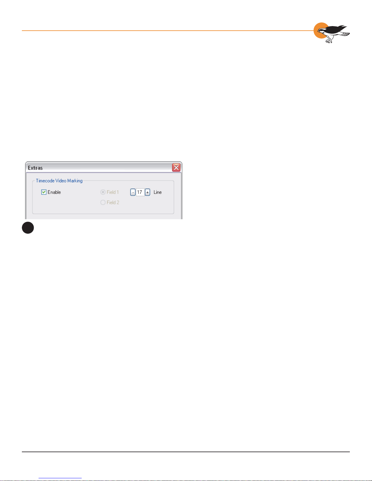
The Timecode Video Marking Controls
20
Chapter 6: Video Driver T opics
The Osprey Timecode Filter also exposes to
applications a custom property and call back
function that allows it to return the VITC
data for each frame along with the frame’s
timestamp to the application. Since use of this
capability requires custom programming it will
not be further discussed here. Refer instead
to the Osprey AVStream SDK Users’ Guide. A
sample SDK applet named TCApp illustrates the
interface.
Timecode stamping must be enabled in the
driver before it can be used, and the field and
line number correctly set. The Osprey-300,
unlike the Osprey-100 and 200 series devices,
does not implement an autosearch function to
find the VITC line. To access the controls, go to
the Device property tab and click the Extras…
button (figure 20).
It is recommended that timecode marking be
disabled when not in use, especially the auto
search feature – on a slow machine it uses
several percent of cpu bandwidth - especially if
timecodes are not present.
Note that VITC and LTC – Longitudinal Timecode
– are two distinct encoding systems, and this
driver supports only VITC.
A suggested reference on timecode is Timecode:
a user’s guide – 3rd ed ., John Ratcliff, Focal
Press, 1999.
VERTI CAL BLANKING INTERV AL (VBI)
C
APTURE
The Osprey-300 does not support VBI raw
capture. It only supports decoded capture of
the two special streams, Closed Caption (CC)
and vertical interval timecode (VITC). If your
application requires VBI capture for WST teletext
decoding or other purposes, and you are using
analog inputs, you can use an Osprey -100 or 200
series device instead.
83

Ospre y -300 Capt ur e Ca r d
The A na l og A ud i o
Drive r
CHAPTER
7
Setup and control for audio are much
simpler than for video. The basic steps are
covered in the following topics:
• Select the Audio Source and Input
Volume
• Audio Format s
• Audio Playback
• Audio Conf iguration
SELECTING THE AUDIO SOURCE AND
I
NPUT VOLUME
The audio source is set using the Osprey300’s mixer driver interface. Most
applications, including the Windows Media
Encoder applications, interface to the mixer
driver directly and expose the look and
feel specific to that application. However,
the default Windows interface to the mixer
driver can also be used. There are two
simple methods for getting to the mixer
source and volume control dialog box.
85

Osprey - 3 00 User ’ s Gui de
• The easiest method for accessing this
interface is to right click the speaker
symbol on your taskbar (typically on the
bottom right-hand side of your screen).
Then select the Open Volume Controls
option (figure 1). (There is a checkbox
in Control Panel -> Sounds and Audio
Devices to make this icon appear.)
• If you do not see the speaker symbol,
click the Start button on the Start
Menu, select Start -> All Programs ->
Accessories -> Entertainment -> Volume
Control.
Either of these two methods brings up the audio
mixer interface for the audio playback device, as
shown in figure 2.
To get to the Osprey-300 audio capture
(recording) device, select Properties under
Recording Control’s Options menu. This pops up
the Properties dialog. Click on the Mixer device
list at the top to see the list of audio input and
output devices, including one or more Osprey300(s). When you have chosen the device, click
OK, and you will be returned to the Recording
Control di s p lay.
Selecting Volume controls on your
1
windows taskbar
The Recording Control window (Audio
2
Mixer Interface)
The Osprey-300 device is not a mixer in that
it does not allow for mixing the various audio
sources. Therefore, when one audio input is
selected, any other input previously selected
becomes unselected. The Select checkbox at
the bottom of each source sets which source is
actually being used.
The Osprey-300 has hardware gain control. To
control hardware gain use the volume slider in
the mixer applet. The unity gain setting is when
the volume slider is in approximately the middle
of the range.
The quick-access volume control (left click on
the speaker symbol) on the task bar controls
recording v olume and pla yback volume. To
change record lev els, go to Options, then
Properties, and select Recording.
86

Chapter 7: The Osprey-300 Audio Driver
AUDI O FORMATS
The Osprey-300 hardware supports sampling
of analog audio at 32, 44.1 and 48 kHz in 16bit PCM format. Captured audio data is downsampled and reformatted if necessary by
Microsoft system audio components, al lowing
an application to capture audio data in 8-bit
and 16-bit mono or stereo formats at an y of the
following data rates:
• 8 kHz
• 11.025 kHz
• 16 kHz
• 22.05 kHz
• 32 kHz
• 44.1 kHz
• 48 kHz
AUDI O P LAYBACK
The Osprey-300 provides audio capture only, not
audio playback. Continue to play back captured
audio using your system soundcard.
AUDI O CONFI GURATI ON
The AudioConfig applet is included as part of
the Osprey AVStream driver package. I t is also
provided in source form in the Osprey AVStream
SDK. It provides supplementary controls that
are not available via the standard system
properties.
AudioConfig’s controls are device-specific and
apply only to Osprey audio capture devices.
Use the Device menu list at the top of the
applet’s window to select which device you are
controlling.
The Audio Configuration Applet
3
87

Osprey - 3 00 User ’ s Gui de
Preferred A u di o Sa mple Rate
The audio sample rate is the rate at which the
hardware samples the incoming audio , which
may differ from the sample rate delivered to the
client application.
The choice are to allow “Any Supported Rate”,
or to force the sampling rate to be 32 kHz ,
44.1 kHz , or 48 kHz. I f “Any Supported Rate”
is selected, all three rates, 32, 44 .1, and 48
kHz, are available for selection by the Microsoft
kmixer driver. Kmixer, however , does not
necessarily select the optimum hardware rate for
a given software rate. It may specify a 44.1 kHz
hardware rate when a supplying 16 kHz software
rate to the application, for example. In this case
it would be better to set the Preferred Audio
Sample Rate 32 kHz, so that downsampling is
exactly 2:1.
When the audio input is SDI, the only sample
rate that the Osprey hardware supports is 48
kHz. The driver will override your setting here.
When the audio input is DV1394, you have to
use this control to match your audio sample rate
to the actual rate of the incoming data. The
two most common formats are 48 kHz / 16-bit,
and 32 kHz / 12-bit. You ma y ha ve to listen to
a captured sample of y our audio to determine
whether the sample rate is set correctly – if the
pitch is incorrect, try the other setting.
Mono Sour ce Mode
This control determines which audio channel will
be the source when monaural audio is selected.
• If set to Use Left Channel, the mono
channel contains audio from the left input.
• If set to Use Right Channel, the mono
channel contains audio from the right
input.
• If set to Average Left and Right, the mono
channel contains the av erage of the two
inputs.
88

Chapter 7: The Osprey-300 Audio Driver
Note that in order to get mono audio you have
to select mono mode in your application. For
example, in SwiftCap you have to select mono
8-bit or mono 16-bit in the Capture Settings ->
Audio -> Format control group.
Because of the wa y DirectShow chooses audio
modes, mono mode only works correctly when
the sample rate you select is an exact match for
an available hardware sample rate. That is, the
sample rate must be 32, 44.1, or 48 kHz in most
cases, and may be further restricted when SDI
or DV1 3 94 is selected (Refer to the explanation
of Preferred Audio Sample Rate, above).
Audio Level
This control sets the hardware Input Reference
level and software-based Boost factor. The
settings are separate for each input of each
device, and are applied to whichever input is
selected in the current application or in the
system mixer. The settings displayed do NOT
automatically update when you change inputs
in the application or mixer – click the “update”
button to refresh the settings.
Balanced and Unbalanced Audio
4
The Input Reference level is meaningful only
on the analog unbalanced and balanced inputs;
when a digital input is selected this control is
disabled. The default level is chosen such that
the expected amplitude of a full volume input
signal will have adequate headroom without
clipping. If you do experience clipping, or are
working with very low -le v el signals, you can
adjust this level. On this control, a higher
reference level results in lower gain, so the
quietest setting is at the top of the scale.
The units, default value and range are different
for unbalanced and balanced signals (figure 4).
Click the “Dflt” button to restore the default
value. The Boost setting can be set individually
for each input. It supplements the system
mixer volume controls by providing a very wide
adjustment range. You can use it to calibrate or
normalize input levels across multiple inputs; or
to accomodate microphones or other non-l ine
inputs that have nonstandard signal levels.
89

Ospre y -300 Capt ur e Ca r d
App lications
CHAPTER
8
SWIFTCAP
SwiftCap is a video capture application
that is included with the Osprey AVStream
package. It is included in source form in
the Osprey AVStream SDK. SwiftCap is
useful for general purpose capture and
viewing of video, as well as for testing the
installation. The following instructions tak e
you through some basic scenarios for using
this application.
The SwiftCap application window
1
Preview
Click the Preview button for a quick basic
test of your video setup, or for basic video
viewing. If you do not see motion video
right away, make sure...
* The correct device is selected
* An input to that device with a live
video feed is selected
* The right NTSC, PAL, or SECAM
video standard is set.
The descriptions below include instructions
to correct these items if necessary . The
steps below will also show ho w to adjust
the size of the video display.
91

Osprey - 3 00 User ’ s Gui de
Setup Sequence
SwiftCap has many possible scenarios and
pathways. The following steps illustrate a few of
the most useful possibilities.
1. Click the “Tools” button to open the
capture settings dialog (fi gure 2).
2. First decide whether you want to capture
video only , audio only, or both; unselected
controls will be disabled – the following
assumes you have selected “Both” ( 2a ).
3. Select your video device and source.
Select “No Compression” (2b ).
4. In the Video Format group , uncheck
“Use Driver’s Default” ( 2 c ).
5. Select the video standard, color
format, frame rate , and video
size you want to use (2 d ).
6. Select your audio de vice and source.
Select “No Compression” (2e ).
7. In the Audio Format group, check “Use
Default” for this experiment (2f).
8. Click OK (2g).
The Capture Setting Dialog
2
Next, click the Destination button to open the
Capture Destination dialog (figure 3):
1. In the video section, select “Renderer” ( 3a ).
2. Select “VMR7 Renderer” (3b). Note
that there is a discussion of renderers
in the Video Capture Topics chapter.
3. In the audio section, select “Renderer” (3c).
4. Select your sound card as the
renderi n g d e v i ce (3d).
5. Click OK (3e) .
Next, click the Capture or Start button. An
“Active Movie” video window will open on your
screen , and your will hear audio from the capture
source, until you click Stop.
The Capture Destination Dialog
3
92

The Capture Destination Dialog
4
Chapter 8: Applications
A Captur e- t o-File Scen a rio
No changes are mandatory from the previous
setup the Capture Settings dialog. However,
you may want to select a video and/or audio
compressor to obtain a much more compact
captu re file.
In the Capture Destination dialog (figure 4),
make the following changes:
1. In the video section , click the
AVI File button (4a).
2. In the audio section , click the
AVI File button (4b).
3. Select an A VI fi le. Click the >> button
on the right to browse for a fi le. (4c )
4. Select Audio as the A VI Master , and
Capture as the Interlea ving Mode
(4d). If y ou are capturing video only
or audio only , these settings are not
used and the controls are greyed.
5. Click OK (4e).
The Capture Results Dialog
5
After you are finished changing the settings,
click Start, then Stop after a few seconds. The
Capture Results dialog (figure 5) shows capture
statistics, including bytes captured, number
of seconds of capture, and number of frames
captured and dropped. It also has a Play button.
Click this to play back the AVI file with your
default media player.
Cropping
The crop settings obtained in SwiftCap are
compatible with the settings obtainable from the
driver property pages. Once set up in SwiftCap,
they can be applied to other applications as well.
The menu item Settings -> Crop Settings…
brings up the Crop Setting Dialog (figure 6):
1. Click Enable Crop to enable or disable
cropping (6a). There is also a direct
menu item Settings -> Crop Enable
to turn cropping on using the current
crop, or to turn cropping off.
2. Drag the edges or corners of the
cropping rectangle to resize it, or
drag its center to move it (6b).
3. The top / bottom / left / right edit
boxes give a readout of the current
crop boundaries (6c ). You can also
edit these boxes directly to obtain
a precise size or position.
93

Osprey - 3 00 User ’ s Gui de
4. The output size, which is the fi nal size
of the captured video , can be 1X, 1/2X,
or 1/4X the crop size (6d ). There
is also an entry in this drop box by
which you can set a custom size.
5. The sizing grid sets the granularity of your
crop width settings (6e). For example, if
you are capturing in YVU9 format, crop
width must divide evenly by 16 and crop
height must divide evenly by 4. Setting
the sizing grid to 16x 4 ensures that
your crop settings will be correct for
the capture format. The text line below
the drop list shows which color formats
your selected granularity applies to.
6. Click Refresh to update the image
from the video source (6f).
7. Save As… and Load… allow you to save
multiple crop specifi cations for future
reference (6g ). Note that there are
minimum values for crop size and output
size; SwiftCap will reject smaller values.
Also, you cannot specify an output size
that is larger than the crop size.
The Crop Settings dialog
6
Other Featu res
Logo setup: SwiftCap has the menu item
Settings -> Logo Settings… . This selection
directly accesses the driver’s logo property
page; for details, refer to the driver properties
description. There is also a Settings -> Logo
Enable control to directly turn the logo on or off.
Accessing driver properties: Click the circuit
board icon on the toolbar.
NOTE: If you use the driver’s “Size and Crop”
or “Logo” property pages, you will not have the
option of saving different settings for capture
and preview. The Pin Select radio buttons will be
greyed out and forced to the “Both” position.
Cpu meter: T urn on via the menu item View ->
CPU Meter.
Load and save configuration: These two buttons
enable you to save SwiftCap settings for future
use.
Lim i tations and Peculiariti es o f Swift Cap
• The current version of SwiftCap does not
capture or display closed captions.
94

Chapter 8: Applications
• If you select RGB8 greyscale as your color
format, SwiftCap captures in greyscale,
but continues to preview in color. Also,
if you capture to the VMR7 Renderer or
VMR9 Renderer, y ou will get color video;
you will only see greyscale video with the
“Video Renderer” selection.
• The current version of SwiftCap does not
handle Video for Windows devices very
well. The buttons to access the driver’s
Source and Format dialogs do not work.
CCAPP
The Osprey AVStream driver performs raw
capture of NTSC closed caption character
pairs. The character pairs are emitted as a raw,
uninterpreted , DirectShow-standard CC Category
stream.
The CCApp Device Properties window
7
CCApp (figure 7 ) renders Closed Captioning on
video, and also displays it as line mode text in
a separate text box . The View options permit
viewing of no video, video without captions, or
video with captions; and allow the text box to be
shown or removed.
CCApp requires that the filter CCFilter.ax be
present on the system. The driver setup
program installs this filter.
95

Osprey - 3 00 User ’ s Gui de
CROPAPP
CropApp (figure 8) sets up crops visually and
interactively. Its functionality is similar to the
driver’s Size and Crop property page, but it has
the added dimension of graphical placement of
the cropping rectangle on live video. It has about
the same functionality as SwiftCap’s crop setup
dialog.
The functions of the controls on the left hand
side of the video are as follows:
* If multiple Osprey devices are in the
system, you can select the device of
interest from the dropdown list at the
top of the control groups. Click “Device
Properties…” to access controls that are
not explicitly addressed by CropApp.
The CropApp Application window
8
* All operations affect both the Capture and
Preview pin on the device. The driver’s
Size and Crop property page is capable
of setting the Capture and Preview pins
differently. If Simu l S tream i s en a bl ed,
CropApp is hardwired to set up pin pair 0
only – to set up other pins you will have to
go to the driver’s Size and Crop property
page.
* The Reference Image group shows the
video height and width that are the
reference size for cropping operations.
For example, if the reference size is
720x480 and the cropping spec is
720x480 , then the video is effectively
uncropped. This group also states the
basis for this reference size – that is,
whether the video standard is NTSC
(720x480) or PAL/SECAM (720x576 ).
* The Cropping Parameters group is where
the current cropping parameters are
shown. When the Enable button is Off,
the entire video field is shown, with the
crop as an overlayed rectangle. Y ou can
modify the crop in three ways:
By editing the X, Y, Width, and Height
boxes.
With the two sets of arrows adjacent to
these boxes.
96

Chapter 8: Applications
By dragging the center, edges, or corners
of the crop rectangle on the video.
When the Enable button is On, only the crop field
is shown, and the crop settings are not editable.
CropApp will not let you set crops that are
smaller than a minimum width and/or height.
The minimum size in the Osprey-300 driver is 48
wide by 36 high.
The Default Output Size group sets a default size
that applications may choose. Use the slider to
set the approximate size you want, and then if
necessary use the [<] and [>] buttons to fine
tune the setting.
The sizes available in CropApp will always retain
a 1:1 height:width proportion. If y ou w ant
to stretch the video to other proportions, use
the driver’s Size and Crop property page, or
SwiftCap’s crop dialog.
Not all applications use the driver’s default
output size or present it as a choice; you may
have to manually enter the settings calculated by
CroppApp into the application .
CropApp will not let you set an output siz e that
is smaller than a minimum width and/or height.
The minimum size in the Osprey-300 driver is 48
wide by 36 high.
The Granularity group allows you to determine
the allowed sizing increments for the selected
video format. For example, if you select YVU9 in
the drop list, you will see that the video widths
allowed in this format are modulo-16, that
is, 320, 336, 352, etc., and the video heights
allowed are modulo-4 – 240, 244, 248, etc. All
editing of the crop size will snap to the nearest
allowed size.
There are no restrictions on placement of the left
and top of the video – for example, in YVU9 the
width must be 320, 336, etc, but the left side can
be 0, 1 , 2, etc.
97

Osprey - 3 00 User ’ s Gui de
Selecting a format here causes CropApp to use
that format for its own rendering, but it does not
cause that same color format to be selected in
your application. In only ensures that your crop
size will work with that color format when it is
used.
We are finding that the default I420 codec will
not render many output sizes, so when I42 0
granularity is selected, CropApp will observe
the I420 granularity rule but render the video
as YUY2. Since you may see this problem in
other applications, CropApp puts up a reminder
message when it encounters this situation.
If you exit CropApp with the crop Enabled,
that is, the center checkbox checked, the crop
parameters will be set in the driver for any other
application to use. If you exit CropApp with the
crop disabled, the crop parameters will be set for
other applications to use, but cropping will not be
enabled until it is turned on as a separate step.
CropApp requires that the filter OverlayRect.
ax be present on the system. The driver setup
program installs this filter.
LOGOAPP
LogoApp (figure 9) interactively positions and
resizes a logo on live video. The functionality is
similar to that of the driver’s Logo property page,
but you can place and size the logo by dragging
its center, sides, or corners directly on live video.
The control bar across the top allows you to
Enable/Disable logo displa y and select the 24-bit
.BMP logo file. You can size and place the logo
graphically on the video, or you can directly edit
the top/left/height/width boxes. Use the Size
1X button to snap the logo to its original size.
The Colors… button brings up a dialog to enable
color keying, select the key color, and enable
translucent mode.
The Size menu allows you to select full or halfsize video. The Device menu displays a list of
enabled devices and provides access to the
selected device ’s property pages.
The LogoApp Application window
9
98

Chapter 8: Applications
LogoApp sets the same logo spec for both the
Capture and Preview pin. If SimulStream is
enabled, LogoApp will set only Pin Pair 0. To set
up other pin instances, or to set the capture and
preview pins differently, use the driver’ s Logo
property page.
VIDCONTROL
VidControl (figure 10) controls the video source,
standard, and settings of Osprey AVStream
Capture Devices. It is useful for initial setup of
devices. Use the Devices menu to select among
multiple devices.
The VidControl Application Window
10
99

Ospre y -300 Capt ur e Ca r d
Troubleshooting
CHAPTER
9
BLUE/PINK/BLACK/ORANGE
V
IDEO SCREEN
The currently selected video input is not
receiving an active video signal. Different
inputs may provide a different symptom
when a video source is not supplied.
* Check that the camera, VCR, or
other video source is powered and
that its output is connected to the
Osprey card’ s input.
* Check that the correct video input
is selected in the Control Dialog’s
Source page.
SCRAMBLED VIDEO IMAGE
You ma y have set the wrong video signal
format for the signal input you are using.
For example, you may have told the driver
to look for NTSC-M video but are using a
PAL-BDGHI video source. Make sure you
know what signal format your video source
is generating. Go into the Video Standard
field of the Control Dialog’s Source page,
and click the button for that signal format.
101

Osprey - 3 00 User ’ s Gui de
POOR V IDEO QUALITY AT LARGE FRAME
S
IZES
Large frame sizes with the deep pixel depth (24or 32-bit), or complex format (YVU9 or YUV12
planar), impose heavy demands on the PCI bus’s
data transfer capacity. Our experience is that
some systems cannot handle these formats at
full frame sizes.
CANNOT PLAY BACK RECORDED AUDIO
If you have a sound card installed, you should be
able to hear audio when you play back recorded
audio.
* Verify that the volume control for your
playback device is not muted.
* Verify that the selected playback device is
your sound card, and not the Osprey-300
Systems vary in their data transfer limits. The
characteristics of the PCI bridge are often more
important than processor speed. I f y ou are
having problems, we recommend that you:
* Use a smaller frame size (480x3 20 or
less).
* Use a shallower color format (RGB15 or
RGB24 instead of RGB32 ).
* Try an RGB format instead of a YVU
format, and a packed format instead of a
planar format.
* If you have a choice of PCs for video
capture, try using another system with a
different system board chipset.
MULTIPLE HORIZONTAL LINES ACROSS
V
IDEO
If there are multiple, regularly spaced, horizontal
lines across your video image and y our source
material is copyrighted and copy-protected, you
are seeing Macrovision™ copy protection.
The lines can vary in color from yellow to blue
to green. These lines are not present in every
frame of video. There may also be a black band
at the top of the frame.
The Osprey 300 cannot eliminate these video
artifacts. These artifacts will only be present
when you are using a copy-protected source,
such as a high-quality D VD for testing a card.
Placeholder device. The Placeholder device exists
in order to handle the situation where there is an
Osprey-300 present without a sound card. Some
Windows applications cannot use a recording
device unless a playback device is also installed.
The Placeholder device cannot pla y back
recorded audio. You can use the same method
to select playback device that you use when
selecting the audio source.
DV Audi o Is Too Slo w/Lo w-Pitched or Fast/
High-Pitched
When the audio input is DV1394, you have to
use the AudioConfig applet’s Preferred Audio
Sample Rate control to match your audio sample
rate to the actual rate of the incoming data. The
two most common formats are 48 kHz / 16-bit,
and 32 kHz / 12-bit. You ma y ha ve to listen to
a sample of your captured audio to determine
whether the sample rate is set correctly – if the
pitch is incorrect, try the other setting.
AUDI O RECORDING CONTROL COMES
U
P WITH WRONG DEVICE AND WRONG
I
NPUTS
The cause of this problem may be that you
currently have or have had previously, a Video
for Windows audio capture driver installed in the
system. The Osprey AVStream install process
normally removes a previous Video for Windows
driver, but if you have multiple Osprey cards
installed you do have the option of running the
Video for Windows driver on some cards and the
AVStream driver on others.
102

Chapter 9: T roubleshooting
Unfortunately the Recording Control does not
work smoothly in this situation. The Video for
Windows device will always try to act like it is
the selected device even if it is not. You have to
manually enter Recording Control’s Options - >
Properties dialog to select your device.
If you no longer have need for the Video for
Windows driver, you can uninstall it using
instructions obtainable from Osprey technical
support. If you are comfortable using RegEdit
to edit your registry, you can instead go to the
followi ng l ocati on:
HKEY_LOCAL_MACHINE\SOFTWARE\Microsoft\
Windows NT\CurrentVersion\Drivers32
Delete all REG_SZ entries named “mixer” or
“mixer1” .. “mixer9” that have the name of an
Osprey mixer as their data. These names will be
o2ca_mix.dll, o5ca_mix.dll, or o300_mix.dll.
INTERRUPT CONFLICTS
Failed network connections, failure of a device
drive to initialize during start-up, or failure of the
Osprey card and driver to operate properly are
often traced to interrupt (IRQ) conflicts. In our
experience, I RQ conflicts are most commonly
seen when a PCI SCSI adapter, or possibly a PCI
network adapter, is present in the system.
Confl icts Between PC I Ca rds
PCI cards and drivers do not choose which I RQs
they use; rather, the operating system assigns
IRQ lines to PCI cards. The IR Q configuration
for the Osprey card or cards is determined
by Windows XP and the Osprey driver cannot
change this configuration. Howe v er, you can
cause the operating system to assign IRQs
differently by rearranging cards or changing
BIOS settings.
Multiple PCI cards are supposed to be able to
share the same IRQ line. In practice, occasionally
you may encounter a device driver that is not
implemented correctly for interrupt sharing. If
this problem arises, you have to rearrange the
PCI cards so that the non-compliant card does
not share its IRQ line with any other device.
Another problem is that some PCI device drivers
expect to use a particular IRQ line.
When a new card is added, it causes the system
to assign IRQs differently. If the IRQ assignment
for a particular card is changed and its device
driver does not detect the change, this causes
the system to work incorrectly.
The simple answer to this problem is it can
sometimes be solved by physically rearranging
the PCI cards such that their arrangement in
the PCI slots is different. When doing this, keep
careful notes of the arrangements you have
tried.
Another approach to PCI card conflicts is at the
BIOS level. Depending on what kind of system
BIOS you hav e , you may be able to change which
IRQ lines are allocated to PCI devices versus ISA
devices. You may be able to allocate more IRQ
lines for PCI devices and thereby solve a PCI
conflict.
Confl icts of PCI Cards with ISA Cards
A PCI card and an older-style ISA card can never
share IRQ lines. Unfortunately, if a device driver
for an ISA card has failed to initialize because of
an IRQ conflict, the card’s IRQ does not appear in
the list. To find the conflict, you ha v e to examine
all your ISA cards with the Control Panel to find
out what IRQs they are trying to use.
If these approaches do not work, see Getting
Help in Chapter 1.
103

Ospre y -300 Capt ur e Ca r d
Har dwar e Specifi cations
APPENDIX
A
Table A-1 Physical Dimensions
Length 167 mm
Width 18 mm
Height 106 mm
Weight 78 grams
Table A- 2 Environmental Specifications
Operating Temperature
Range
Non-Operating
Temperature Range
Operating Hum i d ity
Range
Non-Operating
Humidity Range
Operating Altitude
Range
Non-Operating Altitude
Range
0º to 40º C
-40º to +75º C (RH)
5% to 80% (non-condensing) @
40º C
95% RH (non-condensing);
gradient 30% per hour
0 to 3,048 meters (10,000 feet)
0 to 15,240 meters (50,000
feet)
105

Ospre y -300 Capt ur e Ca r d
Speci a l Regi st ry Settin gs
APPENDIX
B
All of the registry variables described here affect all
devices and all capture or preview pins controlled
by the driver. They do not have to be present in
the registry and are not created by the basic driver
install. If they are not present then the driver
will use its internal defaults. These variables are
located in the registry at the highest lev el of the
driver’s directory twig.
\\HKEY_LOCAL_MACHINE\SYSTEM\
CurrentControlSet\Services\o300avs
Use RegEdit or similar registry editor to add or
modify them at this place. Generally, you will have
to restart the driver to force it to read the new
values – and the most foolproof way to restart the
driver is to restart the system.
With versions 3.1.1 and later of the AVStream
driver you can alter the list of video formats
available on capture and preview pins by editing
the registry. You can also alter the number of
video buffers that are allocated for each capture
pin.
Lists of video formats are represented as string
variables in the registry. They are located at the
highest level of the driver’ s directory twig:
These variables affect all devices There are three of
these REG_SZ ( string) variables:
• CaptureMap determines what formats are
exposed on capture pins.
• PreviewMap1 determines what formats are
exposed on preview pins when Hardware
Deinterlace is disabled .
• PreviewMap2 determines what formats are
exposed on preview pins when Hardware
Deinterlace is enabled.
The first character in each four-character descriptor
is a hexadecimal number for the color format. The
color format hex numbers that are currently valid
are as follows:
RGB32: 1
RGB24: 2
RGB15: 4
RGB8: 5 (or “Y8”, or Greyscale)
YUY2: 7
UYVY: 8
I420: B (11)
YVU9: C (12)
The second character in the four-character
descriptor may be either ‘1 ’ or ‘2’. If ‘2’, the
exposed format is the extended “VIDEO2” format
that includes interlace flags. If ‘ 1’, the format is
the simpler “VIDEO” format that is used for most
capture tasks. If “VIDEO2” is specified, typically
along with YUY2 format, on a pin that is being
directly rendered to screen, man y displa y adapters
will deinterlace the video. Specify plain “VIDEO”
unless you are sure you want “VIDEO2”. R efer to
Microsoft DirectShow docs for more information.
The third character in the descriptor may be either
‘+’ or ‘-’ . ‘+’ means capture or draw the image right
side up, ‘ -’ means capture or draw it upside do wn .
YUV formats should always be ‘+’. RGB formats
should normally by ‘+’ but can be specified as ‘-’ if
a component is making the image upside down.
The fourth character is currently only used as a
visual delimiter . Treat it as reserved and always
make it a space ‘ ‘.
The strings are organized as four-character
descriptors. The first descriptor describes the
first format to appear in the list, and so forth.
The strings can in theory each contain up to 24
des c riptors, or 96 c haracters.
107
 Loading...