

Page 1
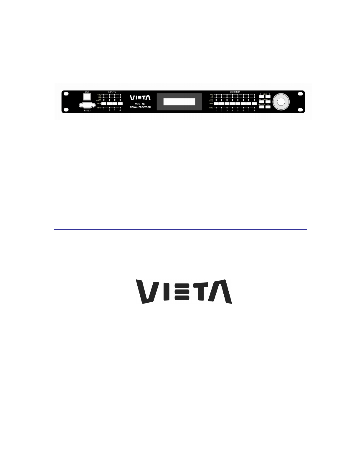
VDC-48
Loudspeaker Management System
User Manual
Page 2
VIE
TA VDC
-
48 User
Man
ual -
Page
2
Important Safety Instructions
1. READ THESE INSTRUCTIONS
All the safety and operating instructions should be read before the product is operated.
2. KEEP THESE INSTRUCTIONS
The safety and operating instructions should be retained for future reference.
3. HEED ALL WARNINGS
All warnings on the product and
in
the operating instructions should be adhered to.
4. FOLLOW ALL INSTRUCTIONS
All operating and use of instructions should be followed.
5. DO NOT USE THIS APPARATUS NEAR WATER
Do not use the product near water. For example, near a bathtub, washbowl, kitchen sink,
or laundry tub,
in a
wet basement, or near a swimming
pool,
and the like.
6. CLEAN ONLY WITH DRY CLOTH
Unplug the unit from the wall outlet before cleaning. Do not use
liquid
cleaners or
aerosol cleaners. Use a damp cloth for cleaning.
7. DO NOT BLOCK ANY VENTILATION OPENINGS
Slots and openings
in
the cabinet back or bottom are provided for ventilation, to ensure
reliable operation of the limit and to protect it from overheating. These openings must
not be blocked or covered. The openings should never be blocked by placing the product
on a bed, sofa, rug, or similar surface. This product should never be placed near or over
a radiator or heat source. This product should not be placed
in a
built-in installation such
as a bookcase or rack unless proper ventilation is provided or the manufacture's
instructions have been adhered to.
Page 3

VIE
TA VDC
-
48 User
Man
ual -
Page
3
8. DO NOT INSTALL NEAR ANY HEAT SOURCES
This Product should be situated away from heat sources such as radiators, stoves, or
other products (including amplifiers) that produces heat.
9. DO NOT DEFEAT THE SAFETY PURPOSE OF THE POLARIZED OR GROUNDING-TYPE
PLUG
A Polarized
plug
has two blades with one
wi
der than the other. A grounding-type
plug
has two blades and a third groun
ding
prong. The wide blade or the third prongs are
provided for your safety. If the provided
plug
does not fit into your outlet, consult an
electrician for replacement of the obsolete outlet.
10. PROTECT THE POWER CORD FROM BEING WALKED ON OR
PI
NCHED
PARTICULARLY AT PLUGS, CONVENIENCE RECEPTACLES, AND THE POINT WHERE
THEY EXIT FROM THE APPARATUS.
11. ONLY USE ATTACHMENTS/ACCESSORIES SPECIFIED BY THE MANUFACTURER.
12. USE ONLY WITH CART, STAND, TRIPOD, BRACKET, OR TABLE SPECIFIED BY THE
MANUFACTURER, OR SOLD WITH THE APPARATUS. WHEN A CART
IS
USED, USE
CAUTION WHEN MOVING THE CART/APPARATUS TO AVOID INJURY FROM TIP-OVER
.
Do not place this unit on an unstable cart, stand, tripod, bracket, or table. The unit may
fall, causing serious injury to someone, and serious damage to the appliance. A unit and
cart combination should be moved with care. Quick stops, excessive force, and uneven
surfaces may cause the product and cart combination to overturn.
13. UNPLUG THIS APPARATUS DURING
LI
GHTNING STORMS OR WHEN UNUSED FOR
LONG PERIODS OF
TI
ME.
For added protection for this unit during a
lightning
storm, or when it is left unattended
and unused for
long
periods of time, unplug it from the wall outlet and disconnect the
antenna or cable system. This
will
prevent damage to the unit due to
lightning
and power
line surges.
14. REFER ALL SERVICING TO QUALIFIED SERVICE PERSONNEL. SERVICING
IS
REQUIRED WHEN THE APPARATUS HAS BEEN DAMAGED IN ANYWAY, SUCH AS
WHEN THE POWER SUPPLY CORD OR PLUG
IS
DAMAGED,
LI
QUID HAS BEEN SPILLED
OR OBJECTS HAVE FALLEN INTO THE APPARATUS, THE APPARATUS HAS BEEN
EXPOSED TO RAIN OR MOISTURE, DOES NOT OPERATE NORMALLY, OR HAS BEEN
FROPPED.
15. WARNING: TO REDUCE THE RISK OF FIRE OR ELECTRIC SHOCK, DO NOT EXPOSE
THIS APPARATUS TO RAIN OR MOISTURE.
16. APPARATUS SHALL NOT BE EXPOSED TO DRI
PPING OR
SPLASHING AND NO
OBJECTS FILLED WITH LIQUID
S,
SUCH AS VASES, SHALL BE PLACED ON THE
APPARATUS
.
Page 4

VIE
TA VDC
-
48 User
Man
ual -
Page
4
Table of Contents
Table of Contents ................................................................... 4
1.0 Introduction .................................................................... 5
2.0 Features .......................................................................... 6
3.0 Front Panel Functions ................................................... 7
4.0 Rear Panel Functions .................................................... 9
5.0 Powering Up the Device .............................................. 10
6.0 Operating the Channel Menus .................................... 11
7.0 Operating the System Menus ..................................... 18
8.0 Quick Reference........................................................... 25
9.0 PC Control Software .................................................... 26
10.0 Specifications............................................................... 27
11.0 Warranty........................................................................ 29
Page 5

VIE
TA VDC
-
48 User
Man
ual -
Page
5
1.0 Introduction
The
VDC-48 is a
digital loudspeaker management system designed for
the touring or
fi
xed sound installation markets. The absolute latest in
available technology is utilized with 40-bi
t fl
oating point processors and
high performance 24-bit Analog Converters. The high-bit DSP prevents
noise and distortion induced by truncation errors of the commonly used 24bit fixed-point devices.
A
complete set of parameters include
I/O
levels,
delay, polarity, 8 bands of EQ per channel, 31 bands of GEQ per input,
multiple crossover selections and full function limiters. Precise frequency
control is achieved with its 1 Hz resolution. Inputs and outputs can be
routed in multiple configurations to meet any requirement. The
VDC-48
can be controlled or configured in real time on the front panel or with the
intuitive PC GUI accessed via
the
RS-232, USB or Ethernet interface.
Software upgrade for CPU and DSP via PC keeps the device current with
newly developed algorithms and functions once available. Multiple setup
storage and system security complete this professional package.
Shipped
contents:
-
VDC-48
Unit
- User Manual
- XConsole Software CD
- Power Cord
Page 6

VIE
TA VDC
-
48 User
Man
ual -
Page
6
2.0 Features
>
Up to 8 Inputs and 8 Outputs with flexible routing
>
40-bit floating point DSP
>
96kHz Sampling Rate
>
High Performance 24-bit A/D Converters
>
1 Hz Frequency Resolution
>
8 Equalizers (Magnitude or Phase) for each Input and Output
>
31 Bands GEQ for each Input
>
Multiple Crossover types with Full Function Limiters
>
Precise Level, Polarity and Delay
>
CPU and DSP upgrade via PC
>
Individual Channel Buttons with Linking capability
>
2-Line x 16 Character Backlit LCD Display
>
Full 5-segment LED’s on every Input and Output
>
Storage of up to 30 Preset Setups
>
Security Lock
>
Ethernet, USB and RS232 Interface for PC Control and Configuration
Page 7
VIE
TA VDC
-
48 User
Man
ual -
Page
7
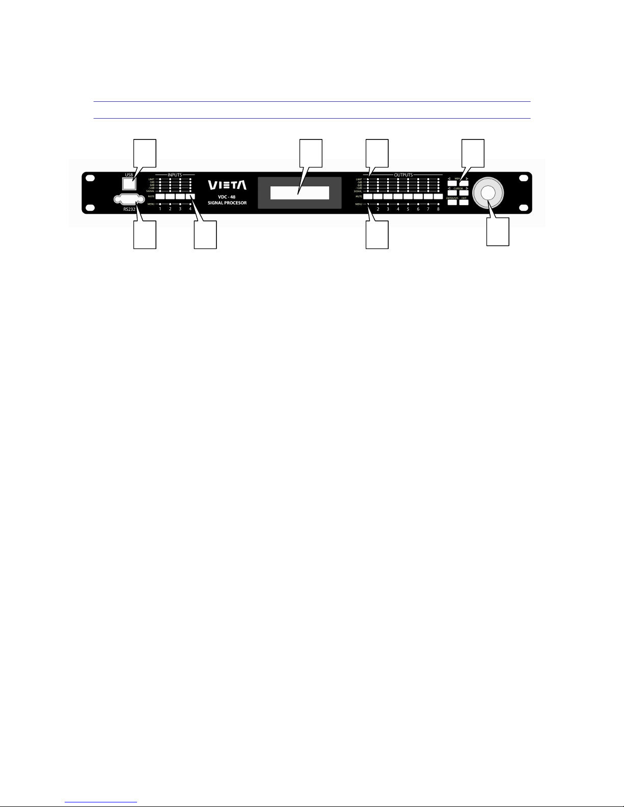
3.0 Front Panel Functions
1. USB – a standard Type
B
USB connector. Device driver from the
provided software CD must be installed prior to usage.
2. RS232 – a standard female DB9 socket.
A
straight through cable is
required for PC connection.
3. Mute (Channel Menu) Buttons – Mute or un-mute input and output
channels. When an input channel is muted, a red LED will come on for
indication.
When the
<<
Menu or Me
nu>>
key is held down, the Mute Buttons
selects the corresponding channel for the LCD menu display and is
acknowledged by a green LED below the button. The last modified
menu will be displayed on the LCD. Multiple channels can be linked or
unlinked by pushing the desired channels. This eases programming for
same parameters across multiple channels. Multiple Inputs can be
linked together and multiple outputs can be linked together. Inputs and
Outputs are linked separately.
4. Channel Menu LED – Indicates
the
activated
channels
for
data
modification.
1
2 3 4
5
6 7
8
Page 8

VIE
TA VDC
-
48 User
Man
ual -
Page
8
5. Peak Level LED – Indicates the current peak level of the Signal:
Signal, -12dB, -6dB, -3dB, Over/Limi
t.
The Input Limit LED references
to the device's maximum headroom. The Output Limit LED references
to the threshold of the output limiter.
6. LCD – Shows all the necessary information to control the uni
t.
7. Menu Buttons – There are 6 menu keys: <<Menu (Menu Down),
Menu>> (Menu Up), <<Cursor (Cursor Down), Cursor
>>
(Cursor Up),
Enter/Sys/Speed, Exit
.
The functions of each key is explained below:
<<Menu:
Go to previous menu screen. Holding this button
down while pressing Mute key will go to the specify
channel menu.
Menu>>:
Go to next menu screen.
Holding this button down
while pressing Mute key will go to the specify
channel menu.
<<Cursor:
Go to previous cursor in the menu screen.
Cursor>>:
Go to next cursor in the menu screen.
Enter/Sys/Speed: Enter is used only in the System Me
nu to
proceed
with selected actions.
Sys enters the System Menu from the main menu.
Speed modifies delay and frequency (1 Hz
resolution mode) data values by 100X.
Exit:
Exit to the Main Menu
.
8. Rotary Thumb Wheel – Changes parameter data values. The wheel
has travel velocity sensing which ease large incremental data
modifications. For modifying delay and frequency (1 Hz resolution),
pressing the Speed key simultaneously will increment/decrement the
data value by 100X.
Page 9
VIE
TA VDC
-
48 User
Man
ual -
Page
9
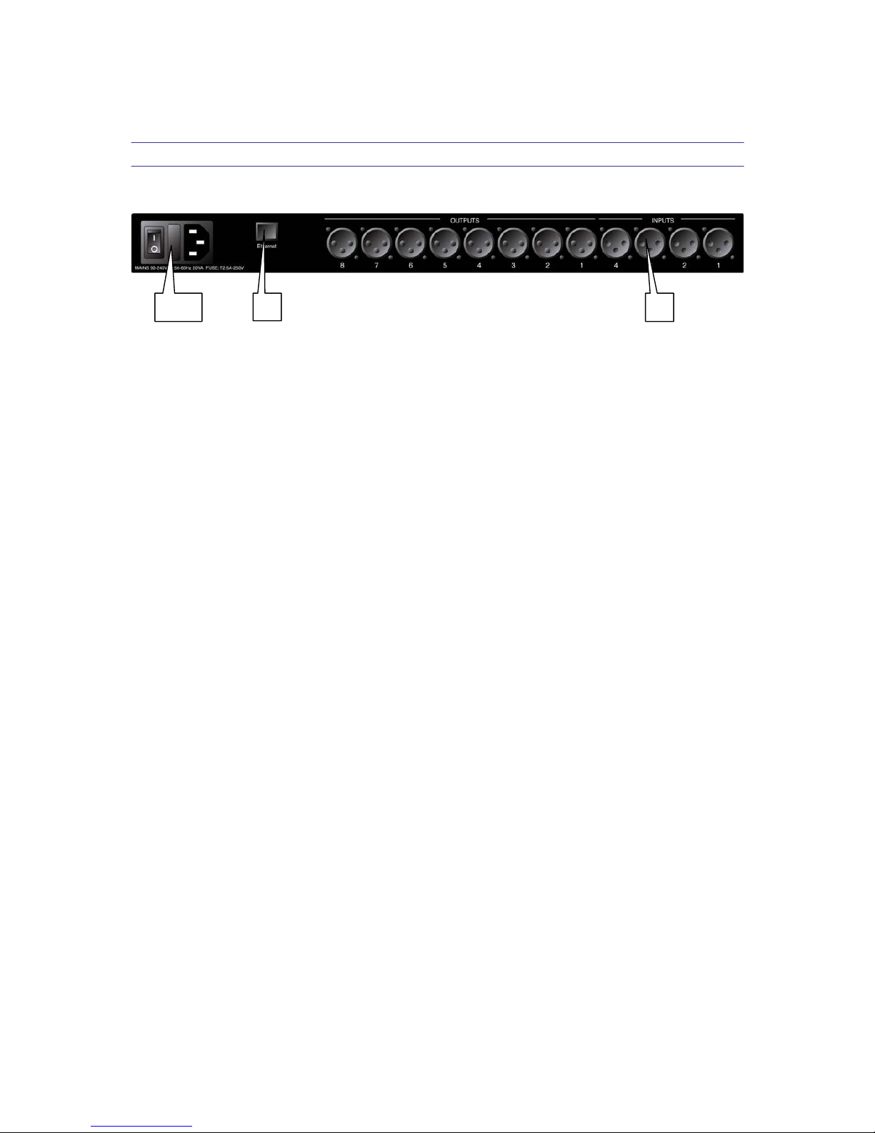
4.0 Rear Panel Functions
1,2,3 4 5
1. Main Power – Connects via a standard IEC socket.
A
compatible power
cord is supplied with the unit. The voltage input is 90-240VAC, 50-60Hz.
2. Main Fuse – T2.5A-250V. Slow blow type.
3. Power switch – Controls power
On/Off.
4. Ethernet – RJ45 connector for Ethernet control.
The device should be
connected to a router/switch/hub via a straight through CAT-5 cable.
5. Analog Inputs and Outputs – Separate 3-pin connectors are provided
for each audio input and output. The device's output stage employs the
balanced impedance topology. All
I/O
connectors have pin 1 as ground
(shield), pin 2 as
+
and pin 3 as
-.
Page 10

VIE
TA VDC
-
48 User
Man
ual -
Page
10
5.0 Powering Up the Device
•
After powering up the unit, the following initialization screen is displayed
on the LCD:
VIETA VDC-48
VDC-48 v7.05
•
The initialization process takes several seconds and during that period
the unit boots and displays the device model and firmware version.
•
After the initialization process is finished the
VDC-48
displays its main
screen:
VIETA VDC-48
P01*
•
The screen shows the current program number and program name
assigned to the unit.
If
the program number is 31 and the name is
MEMORY,
it
means that no program is assigned, the last data before
previous power down is recalled instead.
•
Now the
VDC-48 is
ready to operate.
Page 11

VIE
TA VDC
-
48 User
Man
ual -
Page
11
6.0 Operating the Channel Menus
Channel Linking – While holding down the <<Menu or Menu>
>,
more than
1 channel from the same group (Input or Output group) can be selected to link
the channels together. The green LEDs below the Mute buttons are li
t
for the linked channels.
Any
modification of the data for the selected
channel will be applied to the linked channels as well. To cancel the linking,
simply deselect the desired channel while the <<Menu or Menu>> key is
still pressed, or just press the Exit key to deselect all channels.
6.1
Input/Output Signal
LEVEL:
The level (or gain) ranges from -40.00dB to +15.00dB in 0.25dB steps.
POL:
I1: Signal
LEVEL:0.00dB
The polarity (or phase) can be normal (+) or inverted (-).
I1: Signal
POL:+
Page 12
VIE
TA VDC
-
48 User
Man
ual -
Page
12
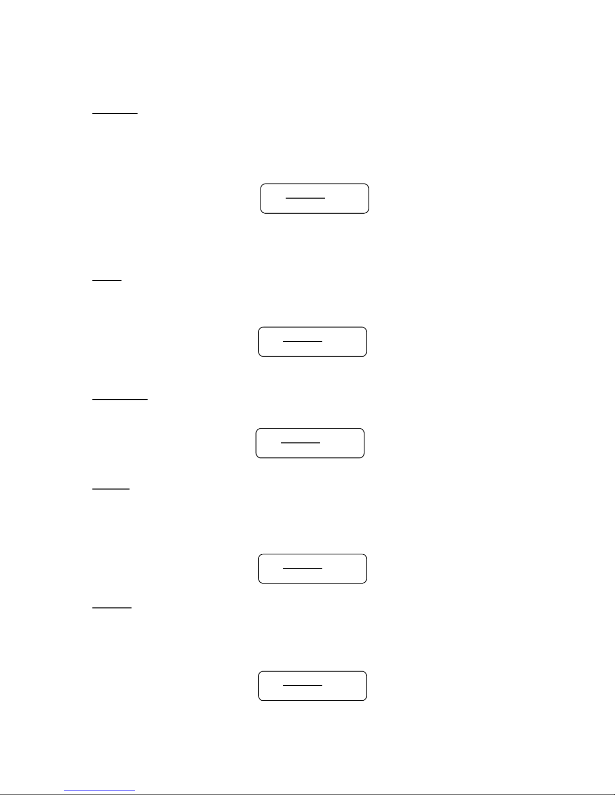
DELAY:
The maximum delay permitted is 650ms, in steps of approximately 10us.
It
can be displayed in ms,
ft or m.
The time unit of the delay is set in the
System
Menu
.
Please refer to page 21 for more details.
I1: Signal
DELAY:000.000ms
6.2
Input/Output
Equalizer
EQ#:
Each input channel has 8 bands of equalization. This control selects one of
the 8 available bands.
I1: EQ1
EQ#:1
BYPASS:
This control will un-bypass
(Off) or
bypass (On) the currently selected band.
I1: EQ1
BYPASS:Off
TYPE:
The 5 types of EQ that can be used are: parametric (PEQ), low shelf (LOSHF), high shelf (HI-SHF), 1
st
degree all-pass (AP-1), and 2
nd
degree all-
pass (AP-2).
I1: EQ1
TYPE:PEQ
FREQ:
The EQ center frequency ranges from 20Hz to 30kHz in either 1Hz steps or
1/36 octave steps. The frequency steps can be selected in the System
Menu
.
Please refer to page 21 for more details.
I1: EQ1
FREQ:1000Hz
Page 13

VIE
TA VDC
-
48 User
Man
ual -
Page
13
BW:
The EQ bandwidth ranges
f
rom 0.02 to 3.61 octaves in steps of 0.01
octave. The equivalent Q value is automatically shown besides the octave
value. For 1
st
degree all-pass (AP-1) filter, the bandwidth will sets the
phase shi
ft at
the centre frequency. This phase shi
ft is
gradually changed
from 180 degrees above the centre frequency to the specified value.
I1: EQ1
BW:0.33 Q=4.36
I1: EQ1
DEG:15.5 deg
LEVEL:
The EQ level (or gain) ranges from -30.00dB to +15.00dB in 0.25dB steps.
I1: EQ1
LEVEL:0.00dB
6.3
Input
Graphic Equalizer
GEQ#:
The graphic equalizer has 31 bands of equalization from 20Hz to 20kHz
.
This control selects one of the 31 available bands.
The frequency
corresponding to each band is also shown.
I1: GEQ1
GEQ#:1 f=20
LEVEL:
The GEQ level (or gain) ranges from -30.00dB to +15.00dB in 0.25dB steps.
I1: GEQ1
LEVEL:0.00dB
BYPASS:
This control will un-bypass
(Off) or
bypass (On) the entire GEQ for this
channel.
I1: GEQ1
BYPASS:Off
Page 14
VIE
TA VDC
-
48 User
Man
ual -
Page
14
6.4
Input/Output
Crossover
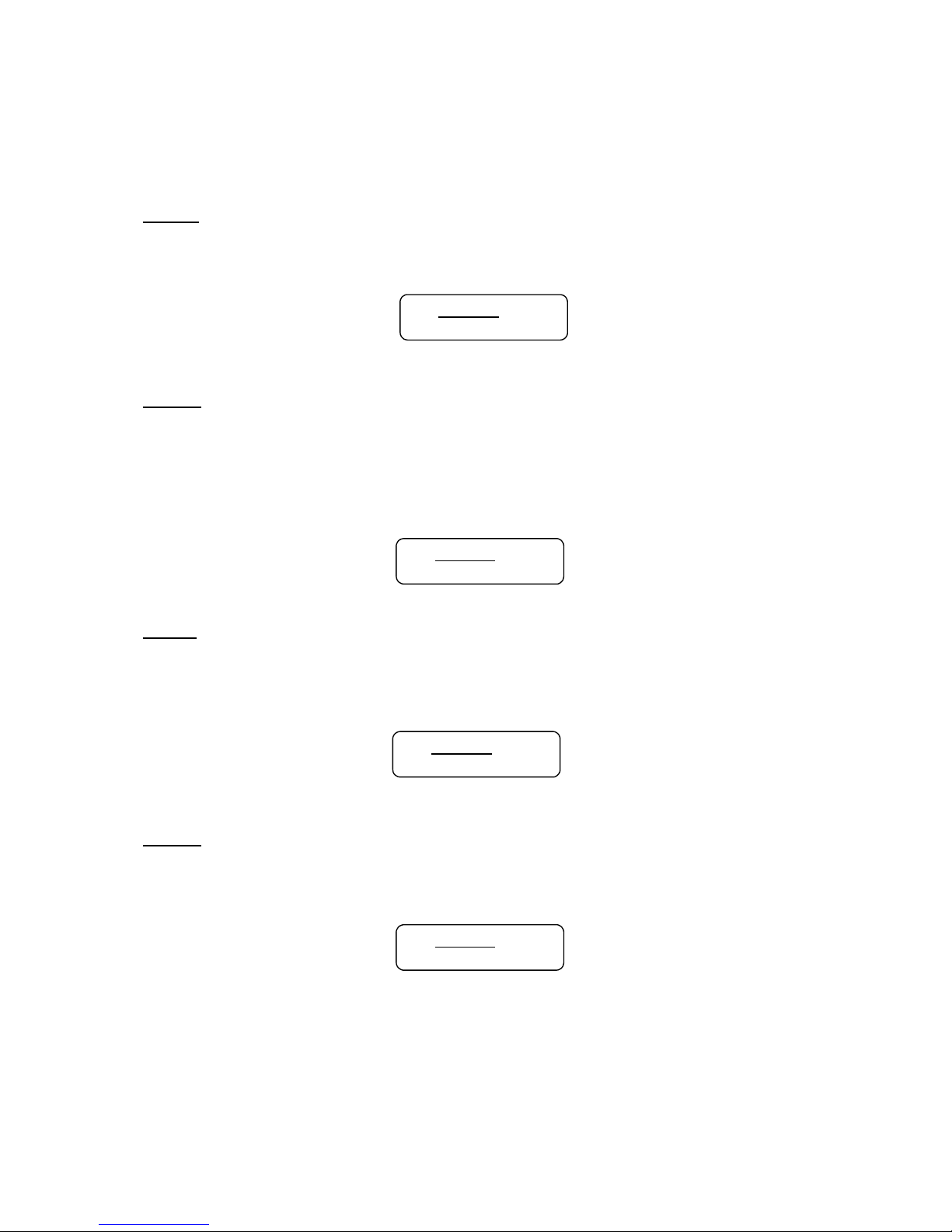
TYPL:
The 3 available filter types for the low frequency crossover point (high pass)
are: Butterworth, Linkwitz Riley or Bessel.
O1: XOver
TYPL:Off
FRQL:
The filter cut-off frequency for the low frequency crossover point (high pass)
ranges from 20 to 30kHz in either 1Hz steps or 1/36 octave steps. The
frequency steps can be selected in the System Menu. Please
refer to
page 21 for more details.
O1: XOver
FRQL:1000Hz
SLPL:
The filter slope for low frequency crossover point (high pass) ranges from 6
to 48dB/octave.
If
the selected filter type is Linkwitz Riley, the available
slopes are 12, 24, 36 or 48 dB/octave only.
O1: XOver
SLPL:24dB
TYPH:
The 3 available filter types for the high frequency crossover point (low pass)
are: Butterworth, Linkwitz Riley or Bessel.
O1: XOver
TYPH:Off
Page 15
VIE
TA VDC
-
48 User
Man
ual -
Page
15
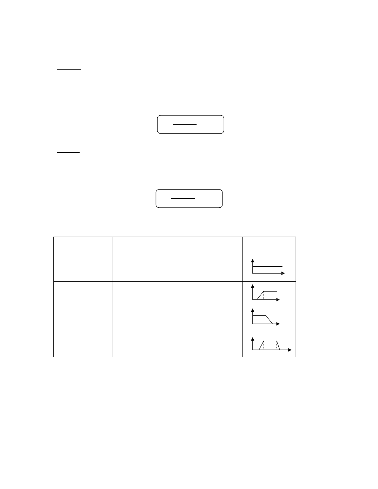
FRQH:
The filter cut-off frequency for the high frequency crossover point (low pass)
ranges from 20 to 30kHz in either 1Hz steps or 1/36 octave steps. The
frequency steps can be selected in the System Menu. Please
refer to
page 21 for more details.
O1: XOver
FRQH:1000Hz
SLPH:
The filter slope for high frequency crossover point (low pass) ranges from 6
to 48dB/octave.
If
the selected filter type is Linkwitz Riley, the available
slopes are 12, 24, 36 or 48 dB/octave only.
O1: XOver
SLPH:24dB
Filter
configuration
Low
crossover
poi
nt
High crossover
poi
nt
None
FTRL
Off
FTRH
Off
Highpass
FTRL not
Off
FTRH
Off
FRQL
Lowpass
FTRL
Off
FTRH not
Off
FRQH
Bandpass
FTRL not
Off
FTRH not
Off
FRQL FRQH
Page 16
VIE
TA VDC
-
48 User
Man
ual -
Page
16
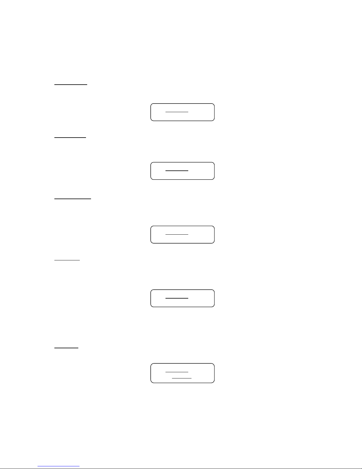
6.5
Input
Compressor
THRESH:
The compressor threshold ranges from -20 to +20dBu in 0.5dB steps.
O1: Comp
THRESH:+20.0dB
ATTACK:
The compressor attack time ranges from 0.3 to 1ms in 0.1ms steps, then
ranges from 1 to 100ms in 1ms steps.
O1: Comp
ATTACK:10ms
RELEASE:
The compressor release
time
can be set at 2X, 4X, 8X
,
16X or 32X the
attack time
.
O1: Comp
RELEASE:8XAtck
RATIO:
The compressor ratio is the slope in which the signal is compressed.
It
ranges from 1:1 to 1:40.
O1: Comp
RATIO: 1:1
6.6
Input/Output
Cha
nnel
Name
NAME:
A 6
characters name can be assigned to each channel.
I1: Name
NAME:
Page 17

VIE
TA VDC
-
48 User
Man
ual -
Page
17
6.7 Output Limiter
THRESH:
The limiter threshold ranges from -20 to +20dBu in 0.5dB steps.
O1: Limit
THRESH:+20.0dB
ATTACK:
The limiter attack
time
ranges from 0.3 to 1ms in 0.1ms steps, then ranges
from 1 to 100ms in 1ms steps.
O1: Limit
ATTACK:10ms
RELEASE:
The limiter release time can be set at 2X, 4X, 8X, 16X or 32X the attack
time.
O1: Limit
RELEASE:8XAtck
6.8 Output Source
IN1-4:
This sets the input channel source for the current output channel.
It
can be
used to mix the input source (in dB) or disable
it (Off). If
more than one
input sources are enabled, they will be added together as the source for the
current output channel.
4
O1: Source
IN1:Off
O1: Source
IN2:-14.00
Page 18

VIE
TA VDC
-
48 User
Man
ual -
Page
18
7.0 Operating the System Menus
The System Menus allow the user to control and change parameters that
are related to the system behavior and general operation.
It
can be
accessed by pressing the Sys key in the main menu (when no Input/Output
or System Menu is activated). All System Menus require pressing the Enter
key to confirm and save the settings.
7.1 Preset Recall
The
VDC-48
has a built in non-volatile memory that can store up to 30
different preset setups.
P:
This control selects which program to recall from the non-volatile memory.
The program name is displayed to the right of the program no.
SYSTEM Recall
P:1
7.2 Preset Store
The
VDC-48
has a built in non-volatile memory that can store up to 30
different preset setups.
A
program can be stored using this menu. The old
program with the same program number will be replaced. Once the
program is
stored in the flash memory,
it
can be recalled at a later
ti
me, even after
power down.
P:
This control selects which preset location in the non-volatile memory to be
saved.
SYSTEM Store
P:1
Page 19
VIE
TA VDC
-
48 User
Man
ual -
Page
19
NAM:
A
descriptive name of up to 12 characters can be assigned to each
program.
SYSTEM Store
NAM:
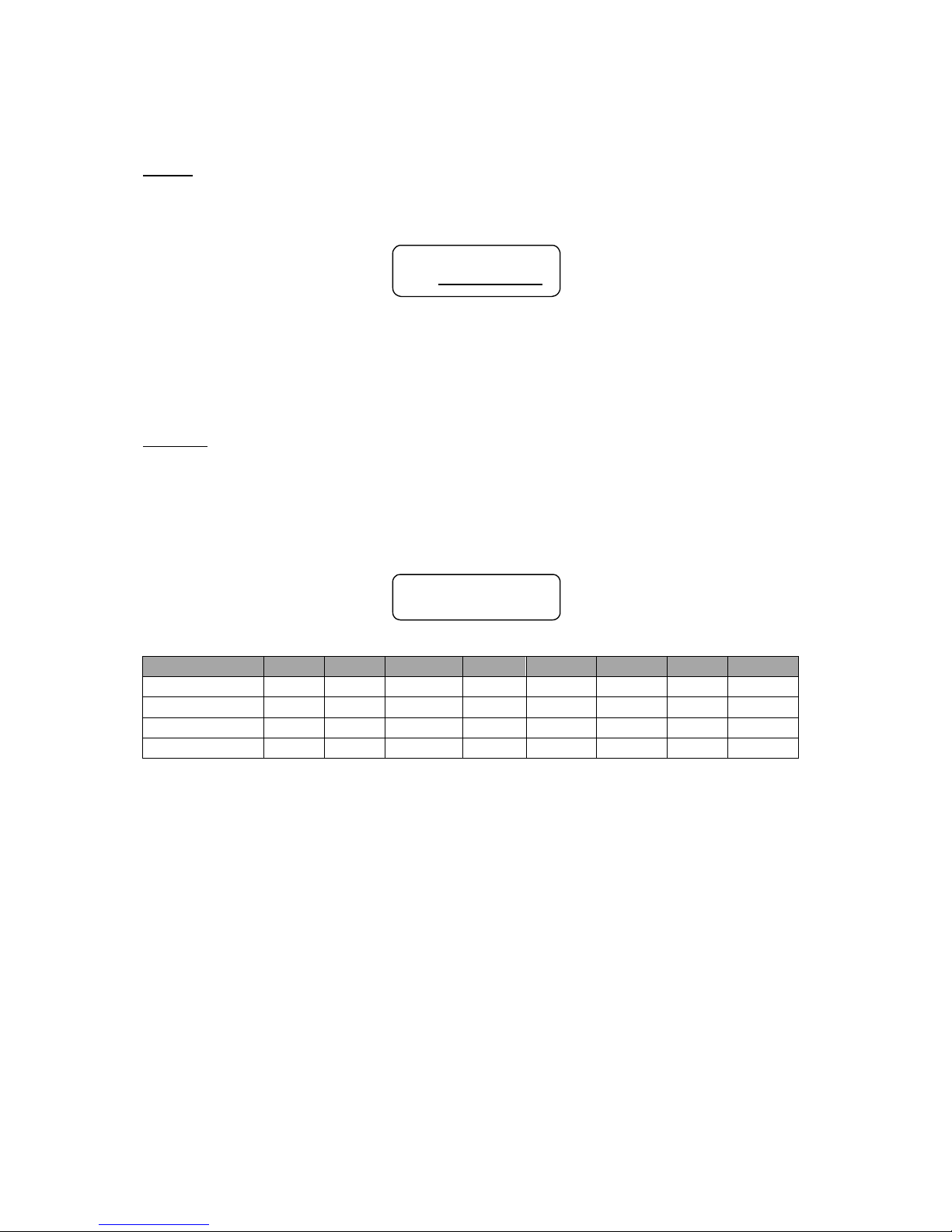
7.4 Device Configuration
MODE:
The unit assigns the Input source for the corresponding outputs when the
Mode of Operation is changed. The crossover point parameters like the
filter type, cut-off
fr
equency and slope have to be configured manually in
the Crossover Menu for each Output Channel.
SYSTEM Config
MODE:None
Mode: Out 1 Out 2 Out 3 Out 4 Out 5 Out 6 Out 7 Out 8
None Any Any Any Any Any Any Any Any
Stereo 2-Way In1 In1 In2 In2 Any Any Any Any
Stereo 3-Way In1 In1 In1 In2 In2 In2 Any Any
Stereo 4-Way In1 In1 In1 In1 In2 In2 In2 In2
*Note: The configuration mode configures the input sources when selected.
The user can change the source afterwards
if
desired.
It
does not keep the
configuration in memory.
7.5 Copy Channels
Copy Channels from the source to the target. When the Source and
Targets are both Inputs and Outputs, all audio parameters will be copied.
When one of the Source or the Target is an input while the other is an
output, only the Level, Polarity, Delay,
EQ,
Crossover, and Channel Name
are copied.
Page 20

VIE
TA VDC
-
48 User
Man
ual -
Page
20
SOURCE:
This is the channel to be copied from
.
SYSTEM Copy
SOURCE:In1
TARGET:
This is the channel to be copied
to.
SYSTEM Copy
TARGET:In2
7.6 General Settings
FREQ MODE:
This changes the frequency control mode for EQ and crossover filters.
It
can be 36 steps/octave or All Frequencies (1 Hz resolution).
SYSTEM Generl
FREQ MODE:All
DELAY UNIT:
This sets the time unit for input and output delay to ms,
ft, or
m.
SYSTEM Generl
DELAY UNIT:ms
Page 21

VIE
TA VDC
-
48 User
Man
ual -
Page
21
7.7 Communication Settings
NOTE: User must power cycle the unit for this settings to take
effect.
BAUD RATE:
The sets the baud rate of the serial communication. XConsole uses a baud
rate of 115200,
it
should be le
ft
unchanged for most user.
SYSTEM Comm
BAUD RATE:115200
DEVICE
ID:
This control assigns a device ID from 1 to 16 to the unit. This ID is only
useful when a network of more than 1 unit is used in conjunction with 1 or
more XPanel.
SYSTEM Comm
DEVICE ID:1
NETWORK
ID:
This control assigns a network ID from 0 to 60000 to the unit. This ID is
used for future network expansion only, please leave
it at 0.
SYSTEM Comm
NETWORK ID:0
7.8 Ethernet Settings
The network settings are separated into 3 menus.
Eth-IP:
A
unique
IP
address should be assigned to each unit in the network.
SYSTEM Eth-IP
:255.255.255.255
Page 22
VIE
TA VDC
-
48 User
Man
ual -
Page
22
Eth-GW:
The gateway address of the network. Usually, this should be the
IP
address
of your router/switch/hub address.
SYSTEM Eth-GW
:255.255.255.255
Eth-SM:
The sets the subnet mask used by your network.
SYSTEM Eth-SM
:255.255.255.255
7.9 Security Password
The factory default password is blank (“
”),
it
can be changed to any
combination of 4 characters in this menu.
OLD
PW:
The user is required to enter the old password first to modify the password.
SYSTEM Passwd
OLD PW:
NEW PW
:
The new password desired.
SYSTEM Passwd
NEW PW:
Page 23

VIE
TA VDC
-
48 User
Man
ual -
Page
23
7.10 Security Lock
The
VDC-48
enables the user to secure the unit and prevent undesired
changes in the setup. In order to lock or unlock the unit the user must
enter the correct password. The user can only lock or unlock all menus
using the front panel, XConsole is required to lock or unlock individual menu.
PASSWORD:
The password is 4 characters in length. The factory default of a new unit
does not require a password. The user can change the password via
XConsole or the Set Password menu.
SYSTEM Secure
PASSWORD:
Page 24
VIE
TA VDC
-
48 User
Man
ual -
Page
24
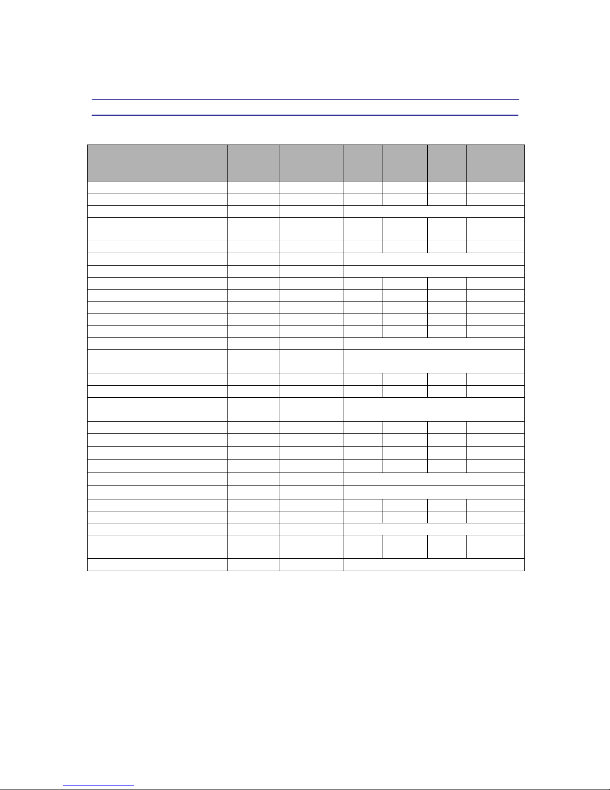
8.0 Quick Reference
Parameters
Menu
<<Menu
>>
Field
<<Cursor>
>
Min
Max
Steps
Units
Mic Level
Mic
LEVEL
0
+45
3
dB
Level
Signal LEVEL
-40
+15
0.25
dB
Polarity
Signal POL
+
/
-
Delay
Signal
DELAY
0
62400
1
10us
steps
EQ Number
EQ
EQ#
1
8
1
EQ Bypass
EQ
BYPASS
Off
/On
EQ Type
EQ
TYPE
PEQ
/
Lo-Sh
f /
Hi-Shf
/
AP-1
/
AP-2
EQ Level
EQ
LEVEL
-30
+15
0.25
dB
EQ Frequency
EQ
FREQ
20
30,000
1
Hz
EQ Bandwidth
EQ
BW
0.02
3.61
0.01
Octave
GEQ Number
GEQ
GEQ#
1
31
1
GEQ Level
GEQ
LEVEL
-30
+15
0.25
dB
GEQ Bypass
GEQ
BYPASS
Off /
On
XOver Low Type
XOver
FTRL
Off /
Butterworth
/
Linkwitz-Riley
/
Bessel
XOver Low Frequency
XOver FRQL
20
30,000
1
Hz
XOver Low Slope
XOver SLPL
6
48
6
dB/octave
XOver High Type
XOver
FTRH
Off /
Butterworth
/
Linkwitz-Riley
/
Bessel
XOver High Frequency
XOver FRQH
20
30,000
1
Hz
XOver High Slope
XOver SLPH
6
48
6
dB/octave
Compressor Threshold
Comp THRESH
-20
+20
0.5
dBu
Compressor Attack Time
Comp ATTACK
0.3
100 0.1
/
1
ms
Compressor Release Time
Comp RELEASE
2
/ 4 / 8 / 16 /
32X Attack time
Compressor Ratio
Comp RATIO
1:1 to 1:40
Limiter Threshold
Limit
THRESH
-20
+20
0.5
dBu
Limiter Attack Time
Limit
ATTACK
0.3
100
0.1/1
ms
Limiter Release Time
Limit
RELEASE
2
/ 4 / 8 / 16 /
32X Attack time
Source
Source
1, 2, 3, 4, 5,
6, 7, 8
Off
+15
0.25
dB
Channel Name
Name NAME
6 characters
Page 25

VIE
TA VDC
-
48 User
Man
ual -
Page
25
9.0 PC Control Software
The
V D C - 4 8 is
shipped with a special PC Graphic User Interface (GUI)
application - XConsole. XConsole gives the user an option to control the
unit
from
a
remote
PC
via
the
serial
communication
link.
The
GUI
application makes
it
much easier to control and monitor the device,
allowing the user to get the whole picture on one screen. Programs can be
recalled and stored from/to PC’s hard drive, thus expanding the storage to
become virtually limitless.
XConsole can be connected to the
VDC-48
via RS232, USB or Ethernet. USB
requires the installation of additional driver. The user is given an
option to install
it
during the installation of XConsole, and
if
the user did not
install
it at
that time, they may choose to do so by running the USB driver
installer from the provided software CD.
Page 26

VIE
TA VDC
-
48 User
Man
ual -
Page
26
10.0 Specifications
Inputs and Outputs
Input Impedance:
>10k Ohms
Output Impedance:
50 Ohms
Maximum Level
:
+20dBu
Type:
Electronically balanced
Audio Performance
Frequency Response:
+/-
0.1dB (20 to 30kHz)
Dynamic Range:
115dB typ (unweighted)
CMMR:
>
60dB (50 to 10kHz)
Crosstalk:
<
-100dB
Distortion:
0.002% (1kHz @+4dBu)
Digital Audio Performance
Processor:
40-bit
Sampling Rate:
96kHz
Analog Converters:
High Performance 24-bit
Propagation Delay:
1.5ms
Front Panel Controls
Display:
2 x 16 Character Backlit LCD
Level Meters:
5 segment LED
Buttons:
Mute/Edit Controls
Menu Controls
Dial Encoder:
Embedded Thumb Wheel
Connectors
Analog Inputs:
3-pin Female XLR
Analog Outputs:
3-pin Male XLR
RS-232:
Female DB-9
USB:
Type
B
Power:
Standard IEC Socket
General
Power:
90-240 VAC (50-60Hz)
Page 27

VIE
TA VDC
-
48 User
Man
ual -
Page
27
Dimensions:
19”x1.75”x9” (483x44x229 mm)
Weight:
10 lbs
/
4.5 kg
Audio Control Parameters
Mic Gain:
0to +45dB in 3dB steps
Gain:
-40 to +15dB in 0.25dB steps
Polarity:
+/-
Delay:
Up to 650ms per
I/O
Equalizers (8 per
I/O)
Type:
Parametric, Hi-shel
f,
Lo-shel
f,
Phase 1, Phase 2
Gain:
-30 to +15dB in 0.25dB steps
Bandwidth:
0.02 to 3.61 octaves (Q=0.3 to 72)
31-Band Graphic Equalizers (1 per Input)
Gain:
-30 to +15dB in 0.25dB steps
Crossover Filters (2 per
I/O)
Filter Types:
Butterworth, Bessel, Linkwitz Riley
Slopes:
6 to 48dB/oct
Limiters (1 per Output)
Threshold:
-20 to +20dBu
Attack:
0.3 to 100ms
Release:
2 to 32X the attack time
System Parameters
No. of Presets:
30
Program Names:
12 character length
Delay Units:
ms,
ft, m
Frequency Modes:
36 steps/oct, 1Hz resolution
Note: Specifications subject to change without notice
Page 28

VIE
TA VDC
-
48 User
Man
ual -
Page
28
11.0 Warranty
The
VDC-48 is
warranted covering materials and workmanship for a
period of two (2) years, as determined by the date of retail purchase
(according to the sales receipt from an authorized dealer) or the date of
manufacture i
f
the sales receipt is not available (according to the serial
number). This warranty applies to the product; therefore, the remainder of
the warranty period will be automatically transferred to any subsequent
owner.
T
his warranty applies only to failure of a VIETA product caused
by defects in materials and workmanship during the stated warranty
period.
It
does not apply to a unit that has been subjected to abuse,
accident, modification, improper handling/installation, or repairs made
without factory authorization
or by
anyone
other
t
han
authorized
VIETA
Field
Service Stations.
This
warranty
is
void
if
the
serial
number has been defaced, altered or removed. Products covered by this
warranty will be repaired or replaced at the option of VIETA, without
charge for materials or labor, provided all the terms of this warranty have
been met.
For factory service, please call or email for a Return Authorization (R/A)
number before shipping.
If
the product is shipped, the following information
must be included in the package:
1. Owner’s complete name, daytime phone number, return street address
and return authorization number.
2. The serial number of the product being returned and a copy of the retail
sales receipt, if possible.
3.
A
complete description of the problem(s) experienced, including a brief
description of how the equipment is being used and other equipments
involved.
Page 29

VDC-48 User Manual V1.1
www.vietapro.com
 Loading...