

Page 1
Technical Data Manual
Model Nos. and pricing : See Price List
VITORONDr 100
Hot water heating boiler 91 to 245 MBH
27 to 72 kW
Product may not be exactly as illustrated.
Vitorond 100
VR1 Series
Oil-Fired Boiler of cast iron sectional construction
for hydronic heating systems with modulating boiler
water temperatures
Heating input: 91 to 245 MBH
27 to 72 kW
5583 772 - 03 07/2014
H
Page 2

Product Information
Vitorond 100
A genuine triple-pass boiler of cast iron sectional design.
The high-quality construction and innovative oil heating
technology of this boiler provides a high level of operational
reliability, high-efficiency operation and reduced emissions.
Benefits at a glance:
Get the most out of your fuel dollar! Maximum heat
extraction with triple-pass design.
A.F.U.E.: up to 86.9%.
Extremely durable cast iron heat exchanger for
maximum reliability and service life.
Clean combustion with Beckett or Riello burners.
Vitorond 100, VR1 Technical Data
Easy access. Full-swing left-hinged or right-hinged
combustion chamber door.
Low maintenance cost with service-friendly burner
and easy-to-clean flue gas passageways.
Spacious, wet-base water walls prevent deposits,
reduce stress and increase boiler life.
Integrated stainless steel combustion chamber insert
for clean and efficient combustion.
Thick 3½” insulation for extremely low standby losses
and fuel savings.
Direct vent option (up to VR1-33) eliminates the need
for a chimney and combustion air supply opening.
Multiple control options: Choose from a standard
24VAC room thermostat or Vitotronic control options
for additional energy savings.
Additional energy savings and reduced emissions with
modulating boiler water temperatures when using
Vitotronic control options.
Boiler return injector available with Vitotronic controls
protects against formation of condensation and enables
safe lower-temperature operation for increased
efficiency.
2
5583 772 - 03
Page 3
Vitorond 100, VR1 Technical Data
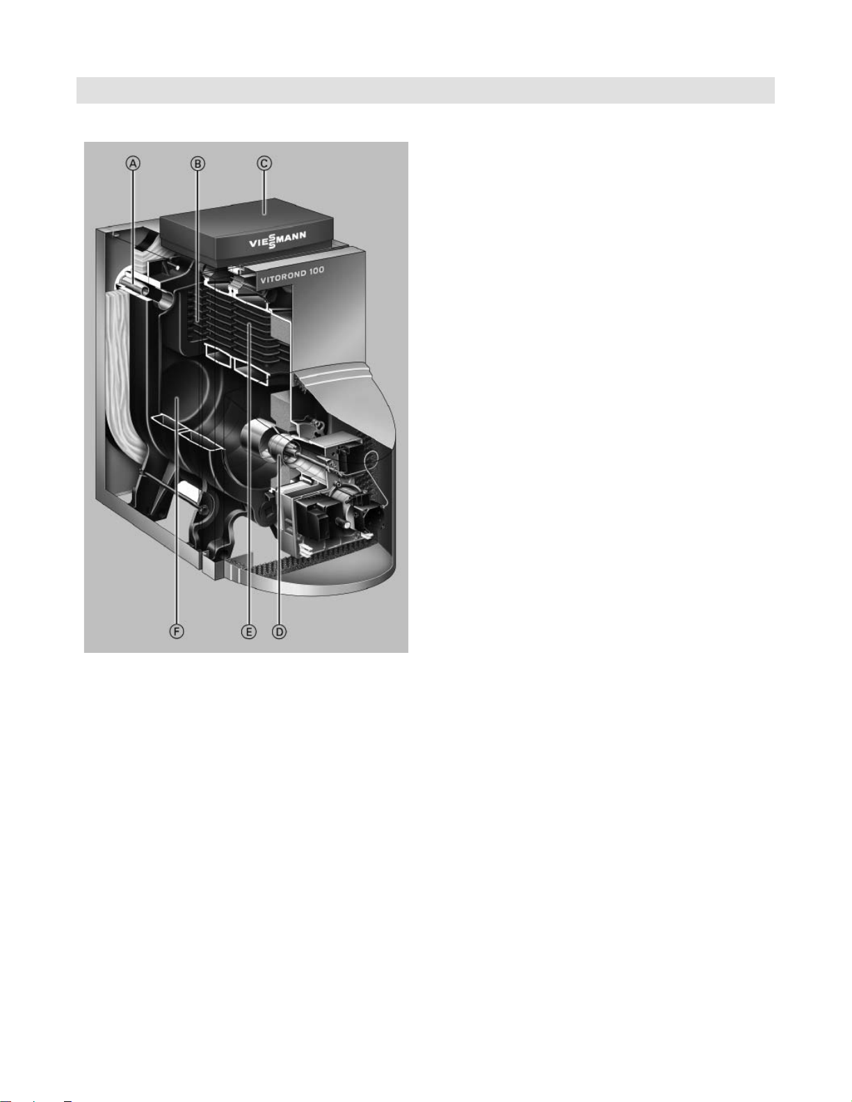
Cutaway Section
Product Information
A Special return water flow control injector
B Eutectoplex heat exchanger surface of special
homogeneous gray cast iron
C Vitotronic 100 - indoor/outdoor digital boiler and
heating system control
D Oil burner
E Third pass
F Combustion chamber*1
*1 Stainless steel combustion chamber insert not shown.
Boiler/burner and controls combination may not be
exactly as illustrated.
5583 772 - 03
3
Page 4

Specifications
Vitorond 100, VR1 Technical Data
Technical Data
Boiler Model No. VR1-22 VR1-27 VR1-33 VR1-40 VR1-50 VR1-63
CSA Input
CSA Output MBH
Net AHRI rating MBH
A.F.U.E. % 86.8 86.8 86.8 86.9 86.9 86.9
Boiler Diamensions
Depth (without burner)
Width
Height
Overall dimensions (with jacket)
Total depth (includes burner)
Total width
Total height (without Vitotronic)
- Height 1 (control unit in position
for operation and programming)
- Height 2 (control unit in position
for servicing)
Height of boiler stand
Weight boiler block
Total weight, boiler with insulation,
burner and boiler control
Boiler water content USG
Max. operating pressure *2 psig
Boiler water connections
Supply and return
Safety supply
Drain valve
Gross flue gas temperature*3 at
- 104° F (40° C) boiler water temp.
- 167° F (75° C) boiler water temp.
Boiler vent connection*4 outer ∅ in.
Required flue draft “w.c.
*1 MBH
(kW)
GPH
(kW)
(kW)
inches
(mm)
inches
(mm)
inches
(mm)
inches
(mm)
inches
(mm)
inches
(mm)
inches
(mm)
inches
(mm)
inches
(mm)
lb
(kg)
lb
(kg)
(L)
(kPa)
in.
in.
in.
°F
(°C)
°F
(°C)
91
27
0.65
80
23
70
21
25½
(650)
15
½
(391)
30½
(775)
38½
(976)
19¾
(500)
33
(840)
43
(1115)
52¾
(1340)
9¾
(250)
265
(120)
363
(165)
9.2
(35)
7
/
8
105
31
0.75
92
27
80
23
31
(790)
½
15
(391)
30½
(775)
44
(1116)
19¾
(500)
33
(840)
43
(1115)
52¾
(1340)
9¾
(250)
335
(152)
445
(202)
11.6
(44)
140
41
1.0
122
36
106
31
31
(790)
½
15
(391)
30½
(775)
44
(1116)
19¾
(500)
33
(840)
7
/
8
43
(1115)
52¾
(1340)
9¾
7
/
8
(250)
337
(153)
447
(203)
11.6
(44)
161
47
1.15
140
41
122
36
½
24
(583)
20
(512)
37
(935)
36
(914)
22½
(565)
39¾
(1010)
50½
(1285)
59½
(1510)
9¾
(250)
410
(186)
492
(223)
12.7
(48)
196
57
1.4
172
50
150
44
½
29
(710)
20
(512)
37
(935)
37½
(956)
22½
(565)
39¾
(1010)
50½
(1285)
59½
(1510)
9¾
(250)
522
(237)
608
(276)
16.1
(61)
245
1.75
215
187
34
(837)
(512)
(935)
42½
(1081)
22½
(565)
39¾
(1010)
50
(1285)
59½
(1510)
9¾
(250)
635
(288)
725
(329)
19.3
(73)
30 30 30 30 30 30
(207) (207) (207) (207) (207) (207)
1½
1½
1½
311
(155)
356
(180)
1½
1½
1½
311
(155)
356
(180)
1½
1½
1½
311
(155)
356
(180)
311
(155)
356
(180)
2
2
2
311
(155)
356
(180)
2
2
2
311
(155)
356
(180)
555666
-0.02 -0.02 -0.02 -0.02 -0.02 -0.02
72
63
55
½
20
37
½
2
2
2
*1 Combustion results are based on 11.0% to 13.5% CO2 with fuel oil #2 and a hot water heating system supply
temperature of 167° F (75° C), return 140° F (60° C).
*2 Max. operating pressure is 45 psig (310 kPa) in all Canadian provinces where a CRN is not required, and in the U.S.A.
*3 Measured flue gas temperature with combustion air temperature of 68° F (20° C).
*4 A 5” vent pipe adaptor is shipped with models VR1-22 to VR1-33. The vent pipe adaptor is not supplied with boiler
models VR1-40 to VR1-63.
For information regarding direct vent applications, please refer to Direct Vent Systems Installation Instruction Supplement.
For information regarding other Viessmann System Technology componentry, please reference documentation of the
respective product.
4
5583 772 - 03
Page 5
Vitorond 100, VR1 Technical Data
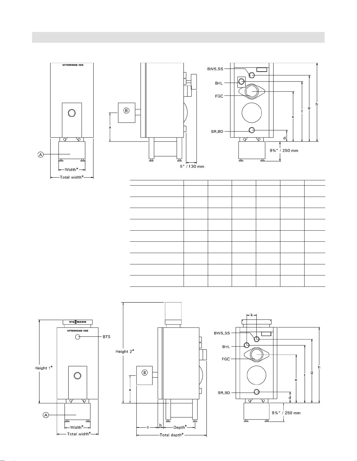
Vitorond 100
Vitorond 100 with Aquastat or Hydrostat
* See page 4
Legend
BD Boiler Drain
BTS Boiler Temperature Sensor
BWR Boiler Water Return
BWS Boiler Water Supply
FGC Flue Gas Collar
SR Safety Return
SS Safety Supply
BHL Boiler High Limit
(with outdoor reset module)
A Boiler Stand
B Beckett or Riello Burner
Specifications
Dimensions
Boiler Model VR1 -22 -27 -33 -40 -50 -63
a in.
(mm)
b in.
(mm)3(75)
c in.
(mm)
d in.
(mm)5½(137)5½(137)5½(137)4¼(107)4¼(107)4¼(107)
e in.
(mm) 23(585)23(585)23(585)
f in.
(mm)
g in.
(mm)
h in.
(mm)33(840)33(840)33(840)
k in.
(mm)5½(138)5½(138)5½(138)6½(166)6½(166)6½(166)
13¼
(338)
12½
(312)
26¼
(667)
28½
(726)
13¼
(338)
3
(75)
12½
(312)
26¼
(667)
28½
(726)
13¼
(338)
3
(75)
12½
(312)
26¼
(667)
28½
(726)
13¾
(347)
3
(75)
12½
(312)9½(247)9½(247)
27¾
(702)
32¼
(822)
34¾
(882)
39¾
(1010)
13¾
(347)
3
(75)
27¾
(702)
32¼
(822)
34¾
(882)
39¾
(1010)
13¾
(347)
(75)
27¾
(702)
32¼
(822)
34¾
(882)
39¾
(1010)
3
Vitorond 100 with Vitotronic Control
5583 772 - 03
* See page 4
5
Page 6

Specifications
Clearances
Minimum Clearances to Combustibles
Vitorond 100, VR1 Technical Data
Standard installation
Boiler Model VR1
Rear
Sides
Flue
Floor
inches
(mm)
inches
(mm)
inches
(mm)
Alcove installation
Boiler Model VR1
Rear
Sides
Flue
Top*2
Floor
inches
(mm)
inches
(mm)
inches
(mm)
inches
(mm)
*1 Front service clearance.
*2 24” with Vitotronic control.
-22 -27 -33 -40 -50 -63
6
(150)
0
(0)
9
(230)
(150)
(0)
(230)
6
0
9
(150)
(0)
(230)
6
0
9
(150)
(0)
(230)
6
0
9
6
(150)
0
(0)
9
(230)
Combustibles
-22 -27 -33 -40 -50 -63
6
(150)
0
(0)
9
(230)
6
(150)
(150)
(0)
(230)
(150)
6
0
9
6
(150)
(0)
(230)
(150)
6
0
9
6
(150)
(0)
(230)
(150)
6
0
9
6
6
(150)
0
(0)
9
(230)
6
(150)
Combustibles
6
(150)
0
(0)
9
(230)
6
(150)
0
(0)
9
(230)
6
(150)
6
5583 772 - 03
Page 7

Vitorond 100, VR1 Technical Data
Specifications
Dimensions
Beckett burner (chimney and direct vent*1 application)
Boiler Model Model No. VR1-22* VR1-27* VR1-33* VR1-40 VR1-50 VR1-63
Burner model Beckett
Fuel type oil No. 2 fuel oil
Pump pressure psig
(kPa)
Oil nozzle Danfoss n.a.
Delavan
Hago
Oil nozzle flow rate GPH@psig
Air tube length inches
(mm)
Air tube insertion inches
(mm)
*1 Direct vent burners available only for sizes VR1-22, -27, -33
For information regarding direct vent applications, please refer to Direct Vent Systems Installation Instruction Supplement.
NX-VI 701 NX-VI 702 NX-VI 703 NX-VI 704 AFG-VI 801 AFG-VI 801
175
(1207)
0.60x60°AS
0.50x60°B
0.50x60°B 0.60x60°B
0.65@175 0.75@175 1.00@175 1.15@175 1.40@175 1.75@175
7
(178)
3¼
(83)
175
(1207)
n.a.
(178)
3¼
(83)
0.75x60°A/W
7
175
(1207)
0.85x60°AH
n.a.
0.85x60°A 1.10x45°W 1.35x60°W
n.a. n.a.
7
(178)
3f
(92)
175
(1207)
(178)
47/
(124)
175
(1207)
n.a. n.a.
1.10x45°W 1.35x60°B
7
9
(229)
8
7¼
(184)
175
(1207)
(229)
7¼
(184)
9
Riello burner (chimney vent application)
Boiler Model Model No. VR1-22 VR1-27 VR1-33 VR1-40 VR1-50 VR1-63
Burner model Riello
F3 F3 F5 F5 F5 F10
40 Series
Fuel type oil No. 2 fuel oil
Pump pressure psig
(kPa)
Oil nozzle Danfoss
Delavan
Hago
Oil nozzle flow rate GPH@psig
Air tube length inches
(mm)
Air tube insertion inches
(mm)
Turbulator setting
Air gate setting
175
(1207)
0.50x60°AS 0.60x60°AS 0.75x60°AS 0.85x60°AH 1.10x60°AH 1.35x60°AH
0.50x60°SS 0.60x60°W 0.75x60°A
0.50x60°SS 0.60x60°ES
0.65@175 0.75@175 1.00@175 1.15@175 1.40@175 1.75@175
7
(178)
4f
(118)
0.0 2.0 0.8 1.0 3.0 2.0
3.1 3.4 2.9 3.5 3.6 2.8
175
(1207)
(178)
4f
(118)
0.75x60°W
7
175
(1207)
n.a.
65/
(160)
4¼
(108)
175
(1207)
0.85x60°A
0.85x60°W
0.85x60°H 1.10x60°H
1.10x60°SS
16
65/
16
(160)
4¼
(108)
175
(1207)
1.10x60°A 1.35x60°A
1.35x60°W
1.35x45°SS
65/
16
(160)
4¼
(108)
175
(1207)
(178)
4¾
(121)
Boiler standard working pressure: 30 psig; maximum working pressure: 45 psig.
Wherever possible, vertically vent the boiler with a properly sized chimney which meets all local and national codes.
Draft at the breech is typically -0.02 to -0.08 “w.c.
7
5583 772 - 03
7
Page 8

Specifications
Vitorond 100, VR1 Technical Data
Dimensions (continued)
Riello burner (direct vent application)
Boiler Model Model No. VR1-22 VR1-27*1 VR1-33
Burner model Riello 40 Series
Fuel type oil No. 2 fuel oil
Pump pressure psig
(kPa)
Oil nozzle Danfoss n.a. n.a. n.a.
Delavan
0.50x60°SS
Hago n.a. n.a. n.a.
Oil nozzle flow rate GPH@psig
Air tube length inches
(mm)
Air tube insertion inches
(mm)
Turbulator setting
Air gate setting
BF3
175
(1207)
0.60x60°W
0.65@175 0.75@175 1.00@140
7
(178)
4f
(118)
0.0 1.0 1.0
3.7 5.0 4.0
*1
BF3
175
(1207)
*3 0.85x60°W*2
7
(178)
4f
(118)
140
(965)
(160)
(108)
BF5
65/
4¼
16
IMPORTANT
*1 For VR1-27 boiler, replace installed nozzle with nozzle
packaged with Riello burner. Riello oil burners are
factory set for Vitorond 100, VR1-22, and -33 boilers
and should only require minor adjustments. Install
appropriate nozzle and set the burner for model VR1-27.
*2 Factory-installed nozzle.
*3 Nozzles must be installed by installer.
Boiler control alternatives
Hydrostat control model 3250-Plus
- High Limit
- with low water cut-off
Vitotronic 100, KW10B
enhanced boiler control for modulating temperature
heating systems with indoor/outdoor system control
Vitotronic 200, KW2
for multiple temperature heating systems with or without
a mixing valve with indoor/outdoor digital boiler and
heating system control
Standard Boiler Equipment
Note: Boiler with controls and burners are purchased
separately. Please see Price List for details.
Boiler shell (insulation preinstalled up to size VR1-33)
30 psig pressure relief valve
Drain valve
The Boiler Stand must be ordered separately.
Installation fittings
Tridicator
Beckett burner c/w Viessmann specified oil nozzle
Riello burner c/w Viessmann specified oil nozzle
8
5583 772 - 03
Page 9

Vitorond 100, VR1 Technical Data
System Design Considerations
Installation
Chimney
For proper operation of the Vitorond boiler, all products of
combustion must be safely vented to the outdoors, while
ensuring that flue gases do not cool prematurely.
It is critical that the chimney system be properly designed
to handle the flue gas temperatures which the Vitorond
boiler produces.
Flue gases which cool too quickly and produce
condensation lead to damages if the chimney diameter is
too large and the chimney system is not well insulated.
If a calculated chimney diameter lies between two
values, the larger diameter should be selected.
Intermediate section
The intermediate (vertical and horizontal) section of
venting between the boiler vent pipe collar and the
chimney must be of the identical diameter as the vent
connection of the boiler. Use the shortest possible path
between the boiler and the chimney. A maximum of two
elbows may be installed in the intermediate section.
Avoid the use of two level 90° elbows.
The intermediate section must be sealed pressure tight at
the boiler vent pipe collar and at the chimney connection.
Ensure any test port for combustion values is sealed as well.
The chimney connection length between the boiler
vent pipe collar and the chimney may be installed with
insulation. We recommend consulting a reputable chimney
installer for advice in project-specific circumstances.
Barometric damper must be used!
Note: Direct Vent exhaust system operates under a
positive pressure developed by the burner. Make
sure all vent connections and observation ports on
the boiler are sealed air tight by tightening screws
and using high temperature silicone sealant if
necessary.
The vent components must be supplied without any
alteration except for the length of the flex pipe which
can be cut to the desired length.
Combustion air supply
The boiler must not be located in areas or rooms where
chemicals containing chlorine, bromine, fluorine, or
other corrosive chemicals are stored. Examples include
refrigerants, bleach, paint, paint thinner, hair spray,
cleaning solvents, water softener salt, etc.
The combustion air must not be contaminated with
the above mentioned, or other aggressive or corrosive
chemicals.
Boiler should never be installed in areas where excessive
dust, high humidity, or risk of frost exist. Ensure adequate
ventilation and supply of fresh combustion air.
Consult Viessmann with uncertainties in regard to a
suitable boiler installation location.
This boiler/burner unit needs clean fresh air for safe
operation and must be installed so that there are
provisions for adequate combustion and ventilation air.
For oil-fired boilers, use the “Installation Code for Oil
Burning Equipment CAN/CSA-B139” (Canada), or NFPA
31 (USA) and/or provisions of local codes.
The sizing methods outlined in the above codes should
be used when installing a round duct to supply
combustion air from the outside. Observe local
jurisdictional requirements.
System layout
The boiler water temperature limit is factory set to 167° F
(75° C) (Vitotronic only).
The boiler water temperature limit can be increased by
altering the adjustable high limit to increase the supply
water temperature.
To minimize piping losses of the system however, we
recommend that the radiation and domestic hot water
production in the system be designed for a 158° F (70° C)
boiler supply water temperature (new systems).
Warranty
Our warranty does not cover damages resulting from the
following:
– installation or service by unqualified and not licensed
personnel
– corrosion caused by flue gas condensation due to low
boiler water and/or return water temperatures
– operation with contaminated fill and supplementary
feed water
For detailed warranty information, please read warranty
sheet supplied with product.
5583 772 - 03
9
Page 10

Installation
System Design Considerations (continued)
Vitorond 100, VR1 Technical Data
Water quality
Treatment for boiler feed water should be considered in
areas of known problems, such as where a high mineral
content and hardness exist. In areas where freezing
might occur, an antifreeze may be added to the system
water to protect the system.
Please adhere to the specifications given by the antifreeze
manufacturer. Do not use automotive silicate based
antifreeze. Please observe that an antifreeze/water
mixture may require a backflow preventer within the
automatic water feed and influence components such
as diaphragm expansion tanks, radiation, etc. A 40%
antifreeze content will provide freeze-up protection to
-10° F (-23° C). Do not use antifreeze other than
specifically made for hot water heating systems.
System also may contain components which might be
negatively affected by antifreeze. Check total system
frequently when filled with antifreeze.
Advise system operator/ultimate owner that system is
filled with a glycol mix.
The heating contractor must provide an MSDS (Material
Safety Data Sheet) for the antifreeze used to the system
operator/ultimate owner.
Oxygen diffusion barrier underfloor tubing
The boiler warranty does not cover leaks resulting from
corrosion caused by the use of underfloor plastic tubing
without an oxygen diffusion barrier. Such systems must
have the non-oxygen diffusion barrier tubing separated
from the boiler with a heat exchanger. Viessmann
recommends the use of underfloor plastic tubing with
an oxygen diffusion barrier.
Low water cut-off
A low water cut-off may be required by local codes.
If boiler is installed above the radiation level, a low water
cut-off device of approved type must be installed in all
instances. An approved type low water cut-off device
must be provided by the, heating contractor. Do not
install an isolation valve between the boiler and the
low water cut-off.
Hydrostat control model 3250 PLUS is equipped with
low water cut-off.
10
5583 772 - 03
Page 11

Vitorond 100, VR1 Technical Data
System Design Considerations (continued)
Installation
Waterside flow
Flow rates
The relationship between boiler flow rate and temperature
rise is according to the formula:
Boiler output (Btu/h) = 500 x flow (USGPM) x Rise (°F)
The following chart lists typical flow rates for the
Vitorond boiler:
Boiler Model VR1 -22 -27 -33
20° F rise
30° F rise
Boiler Model VR1 -40 -50 -63
20° F rise
30° F rise
General
The schematics on the following pages are to be seen
as guidelines only. They further do not display all system
varieties, safety devices, or concepts possible. Specific
system layouts may be further discussed with the local
Viessmann sales representative office.
Clearances
A minimum of 2” circumferential clearance from noninsulated hot water pipes to combustible construction
must be maintained. In cases where the pipes are
insulated with pipe insulation of appropriate and sufficient
thickness and insulation values, the above clearance may
be reduced to 0”.
USGPM 8 9.2 12.2
USGPM 5.3 6.1 8.1
USGPM 14 17.2 21.5
USGPM 9.3 11.5 14.3
Legend
A VR1-22 to -33
B VR1-40 to -63
5583 772 - 03
11
Page 12

Installation
Installation
Installation Examples - Hydrostat
Vitorond 100, VR1 Technical Data
Boiler in a heating/cooling application
Cooling season starts: close valve v1 and open valve v2
Heating season starts: close valve v2 and open valve v1
Legend
A Heating/Cooling unit
B Spring-loaded flow check valve
C Circulation pump
D Automatic air vent,
E Pressure relief valve
F Hydrostat 3250-Plus (with low water cut-off)
G Water chiller
H Expansion tank
IMPORTANT
We strongly suggest that the valves be labelled “v1” and v2.”
Description
Hydrostat model 3250-Plus is equipped with a low water
cut-off feature in combination with ‘electro well’ sensor
well. The function can be set to operate in automatic
(default) or manual reset mode. Do not disable this
function it may be required by local codes.
Legend
A Heating circuit
B Spring-loaded flow check valve
C Circulation pump
D Automatic air vent,
E Pressure relief valve
F Hydrostat 3250-Plus (with low water cut-off)
G Expansion tank
12
5583 772 - 03
Page 13

Vitorond 100, VR1 Technical Data
Installation Examples - Vitotronic
Installation
Without mixing valve
e.g. with Vitotronic 100, Model KW10B
Legend
A Heating circuit
B Spring-loaded flow check valve
C Circulation pump
D Automatic air vent, (field supplied), pressure relief
valve, and temperature pressure gage
E Expansion tank
F Low water cut-off (if required)
Without mixing valve and with DHW
e.g. with Vitotronic 100, KW10B
Legend
A Heating circuit
B Spring-loaded flow check valve
C Circulation pump
D Automatic air vent, (field supplied),
pressure relief valve, and
temperature pressure gage
E Expansion tank
E Domestic hot water storage tank
(indirect-fired)
F Low water cut-off (if required
G DHW storage tank indirect fire
5583 772 - 03
13
Page 14

Installation
Installation Examples - Vitotronic (continued)
With one low-temperature circuit with 4-way mixing valve,
and with domestic hot water production.
e.g. with Vitotronic 200, Model KW2 combined with
one mixing valve actuator accessory kit
Vitorond 100, VR1 Technical Data
Legend
A Heating circuit
B Spring-loaded flow check valve
C Circulation pump
D Automatic air vent, (field supplied),
pressure relief valve, and temperature pressure gage
E Expansion tank
F Domestic hot water storage tank (indirect-fired)
G 4-Way mixing valve
H Low water cut-off (if required)
14
5583 772 - 03
Page 15

Vitorond 100, VR1 Technical Data
Installation Examples - Vitotronic (continued)
With one low-temperature circuit with 4-way mixing valve,
one high temperature circuit, and with domestic hot water
production.
e.g. with Vitotronic 200, Model KW2 combined with
one mixing valve actuator accessory kit
Installation
Legend
A Heating circuit
B Spring-loaded flow check valve
C Circulation pump
D Automatic air vent, (field supplied),
pressure relief valve, and temperature pressure gage
E Expansion tank
F Domestic hot water storage tank (indirect-fired)
G 4-Way mixing valve
H Low water cut-off (if required)
5583 772 - 03
15
Page 16

Vitorond 100, VR1 Technical Data
Printed on environmentally friendly
(recycled and recyclable) paper.
5583 772 - 03 Technical information subject to change without notice.
 Loading...