

Page 1
Gebrauchsanleitung
Manual
Manual
Form-Vorsignal
dreibegriffig, mit zwei Antrieben
Semaphore Distant Signal
three-aspect signals, with two drive units
H0: 4511
TT: 4908
N: 4408
1. Wichtige Hinweise ...................................... 2
2. Einleitung ................................................... 2
3. Aufstellung .................................................. 3
4. Funktionskontrolle ...................................... 3
5. Montage ..................................................... 4
6. Anschluss ................................................... 4
7. Fehlersuche & Abhilfe ................................ 8
8. Technische Daten ...................................... 8
1. Important Information ................................. 2
2. Introduction ................................................ 2
3. Setting up Signals ...................................... 3
4. Checking the Function ................................ 3
5. Mounting ..................................................... 4
6. Connections ............................................... 4
7. Troubleshooting .......................................... 8
8. Technical Data ........................................... 8
Page 2
2
D GB
Fig. 1
Abb. 1
Fig. 2
Abb. 2
Halt erwarten
expect stop
Fahrt erwarten
expect proceed
Langsamfahrt erwarten
expect proceed slowly
Vr0
Vr2Vr1
1. Wichtige Hinweise
Lesen Sie vor der ersten Benutzung des Produktes bzw. dessen Einbau diese Anleitung komplett
und aufmerksam durch. Bewahren Sie diese Anleitung auf. Sie ist Teil des Produktes.
Das Produkt richtig verwenden
Das Produkt darf ausschließlich dieser Anleitung
gemäß verwendet werden. Dieses Signalmodell
ist bestimmt
– zum Einbau in Modelleisenbahnanlagen,
– zum Betrieb an einem zugelassenen Modell-
bahntransformator bzw. an einer damit ver-
sorgten elektrischen Steuerung,
– zum Betrieb in trockenen Räumen.
Jeder darüber hinausgehende Gebrauch gilt als
nicht bestimmungsgemäß. Für daraus resultierende Schäden haftet der Hersteller nicht.
2. Einleitung
Viessmann-Formsignale zeichnen sich durch vorbildgetreu langsame Flügelbewegung, ihr hervorragendes Preis-Leistungs-Verhältnis sowie durch
einfache Montage und Anschlussmöglichkeit aus.
Das vorliegende Formsignal verfügt über zwei
elektromagnetische Antriebe, Endlagenabschaltung und einen Kontakt zur Zugbeeinflussung.
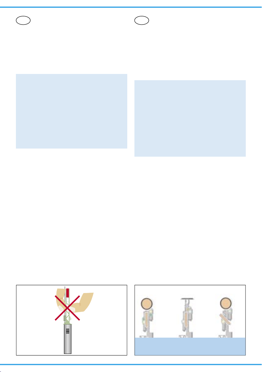
Viessmann-Formsignale haben sehr filigrane Masten, die sich durch eine perfekte Vorbildtreue auszeichnen. Daher sollten Sie das Signal nie am
Mast anfassen, sondern immer nur an der Bodenplatte bzw. am Antriebszylinder (Abb. 1). Bei einem Ausbau aus der Modellbahnplatte nicht oben
ziehen, sondern das Signal unter der Platte am
Antriebszylinder greifen und nach oben hinausschieben!
1. Important Information
Please read this manual prior to first use of the
product resp. its installation! This product must
only be used as required in this manual. Keep this
manual. It is part of the product.
Using the product for it’s correct
purpose
This model of a signal is intended
– for installation in model railroad layouts.
– for connection to an authorized model railroad
transformer or an electrical control system connected to one
– for operation in a dry area
Using the product for any other purpose is not
approved and is considered incorrect. The
manufacturer cannot be held responsible for any
damage resulting from the improper use of this
product.
2. Introduction
Viessmann-Semaphores have some outstanding
benefits: Prototypical slow arm-movement, very
good price-performance-ratio and they are simple
to mount and connect.
This signal has two electromagnetic drive units,
end-position-stop and an integrated contact for
train control.
Viessmann-Semaphores have finely detailed metal masts, which are very sensitive. Therefore you
should never touch the masts but only the drive
unit for installation and deinstallation (Fig. 1)
If you have to unmount the signal, don’t pull the
the signal-mast. Carefully take the drive unit instead and push it up.
Page 3
3
75 m
400 m, 700 m oder 1000 m
100 m75 m
Vorsignalbaken
Hauptsignal
Vorsignal
Warning beacons
Main signal
Distant signal
Fig. 3
Abb. 3
3. Aufstellung
Schienen und Räder der Eisenbahn sind aus
Stahl. Die geringe Reibung von Stahl auf Stahl
bedeutet lange Bremswege. Damit der Lokführer
den Zug vor dem Hauptsignal zum Halten bringen
kann, muss er früh genug erfahren, welchen Signalbegriff das folgende Hauptsignal zeigt. Das ist
Aufgabe des Vorsignals. Das Vorsignal zeigt dem
Lokführer den Signalbegriff des Hauptsignals.
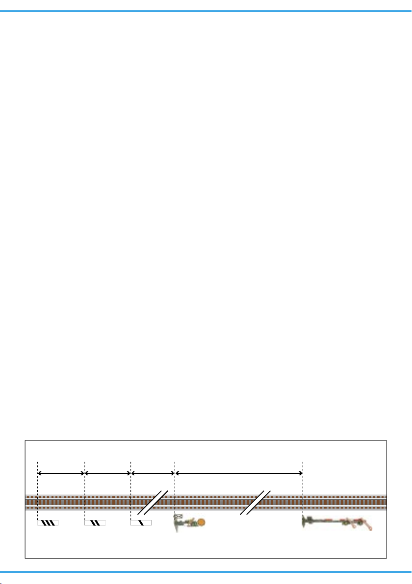
Vorsignale stehen im Bremswegabstand vor dem
Hauptsignal, rechts vom Gleis. Je nach Streckengeschwindigkeit beträgt der Abstand 400 m,
700 m oder 1000 m (Abb. 3).
Der Lokführer darf Vorsignale keinesfalls übersehen. Deshalb werden sie durch Vorsignalbaken
angekündigt.
Viele weitere Informationen über Signale finden
Sie im Viessmann-Signalbuch, Artikel-Nr. 5299.
4. Funktionskontrolle
Nehmen Sie das Signal vorsichtig aus der Verpackung. Führen Sie vor der Montage eine Funktionskontrolle durch.
Schließen Sie dazu das gelbe Kabel (ohne Markierung) an einem Pol eines 16 V-Modellbahntransformators – z. B. Viessmann 5200 – an.
Verbinden Sie abwechselnd jeweils ein blaues Kabel mit dem anderen Pol des Trafos. Schließen
Sie niemals die blauen Kabel gleichzeitig an.
Das kann zur Zerstörung des Signals führen.
Das Signal schaltet in die entsprechenden Stellungen (Abb. 2):
Blau mit roter Markierung:
Signal auf „Halt erwarten“ (Vr0)
Blau mit grüner Markierung:
Signal auf „Fahrt erwarten“ (Vr1)
Blau mit gelber Markierung:
Signal auf „Langsamfahrt erwarten“ (Vr2)
3. Setting up Signals
Wheels and rails of the railway are made of steel.
The friction between steel and steel is very low,
which results in long stopping distances. To prevent accidents caused by the long stopping distance, distant signals were built. A distant signal
shows the aspect of the following main signal on
the topical way.
Distant signals are put up in the stopping distance
in front of the main signal. They stand on the right
side of the track. Dependent on the allowed speed
the distance is 400 m, 700 m or 1000 m (Fig. 3).
To inform the engine driver that a distant signal is
in front of him, warning beacons are put up on the
right side of the track.
These beacons are shown in fig. 3 too. The distance between the beacons is 75 m. The distance
between the last beacon and the distant signal is
100 m.
4. Checking the Function
Remove the signal from the box carefully. Check
all functions prior to installation.
Connect the yellow wire to one of the terminals
of a 16 V transformer (AC/DC) e. g. Viessmann
5200. Then alternately make contact between the
blue cables and the other terminal, but only briefly.
Never connect the blue cables at the same
time to the transformer. This may destroy the
signal.
Connecting the cable results in the following
aspects of the signal (Fig. 2):
Blue with red marking:
Signal on “Expect Stop” (Vr0)
Blue with green marking:
Signal on “Expect Proceed” (Vr1)
Blue with yellow marking:
Signal on “Expect Proceed Slowly” (Hp2)
Page 4

4
Fig. 4
Abb. 4
30 mm
15 mm
Ø 6 mm
Ø 1,4 mm
5. Montage
1. Sägen Sie an der Montagestelle ein Loch mit
den Maßen 30 mm x 15 mm. Bohren Sie dazu
zuerst 4 Löcher mit 6 mm Durchmesser. Verwenden Sie die in der Abbildung 4 abgedruckte
Schablone.
2. Führen Sie die Anschlusskabel von oben durch
das Montageloch und stecken Sie dann das Signal mit dem Antrieb voran hinein.
3. Befestigen Sie das Signal mit den beiliegenden
Schrauben.
6. Anschluss
Alle Anschluss- und Montagearbeiten dürfen
nur bei abgeschalteter Betriebsspannung
durchgeführt werden!
Verwenden Sie nur nach VDE /EN-gefertigte
Modellbahntransformatoren!
Sichern Sie die Stromquellen unbedingt so
ab, dass es bei einem Kurzschluss nicht
zum Kabelbrand kommen kann.
Die Betriebsspannung beträgt 16 V = / ~.
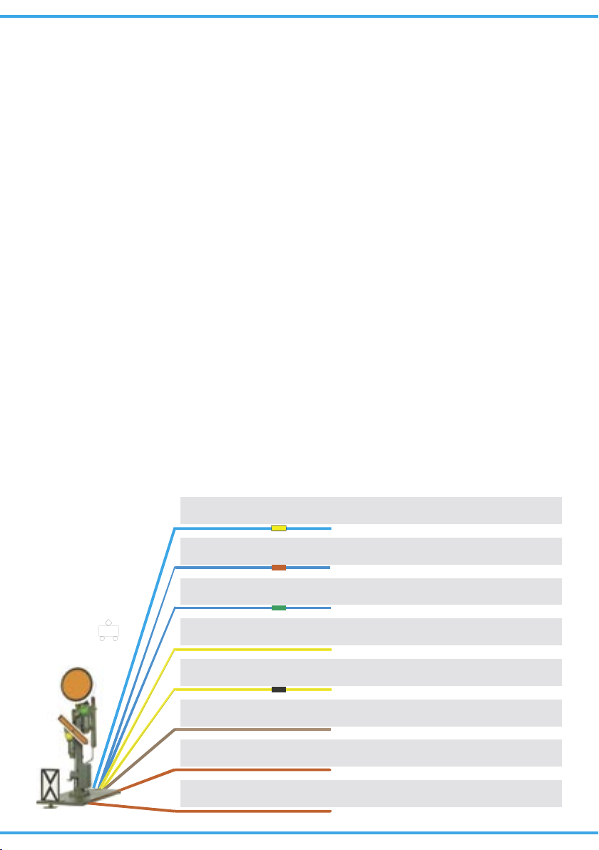
Schließen Sie nun das Signal gemäß den Abbildungen 6 oder 7 an. Zur Bedeutung der Kabelfarben siehe Abbildung 5.
Für die Versorgung der Signalbeleuchtung empfehlen wir einen separaten Transformator. Das
verhindert ein eventuelles Flackern der Beleuchtung beim Umschalten des Signales durch den erhöhten Strombedarf des Antriebes.
Gleichstrombetrieb: Schließen Sie die beiden
gelben Kabel an den Minuspol des Trafos an.
Analoge Ansteuerung
In Abbildung 6 zeigen wir Ihnen, wie einfach
Sie die dreibegriffigen Formsignale mit Hilfe der
Viessmann Tastenstellpulte 5546 (ohne Rückmel-
5. Mounting
1) Saw a square hole of 30 mm x 15 mm at the
mounting place. But before 4 holes of 6 mm diameter each should be drilled in the corners.
Use the pattern which is shown in figure 4.
2) The signal‘s connection wires have to be inserted into the hole first. After that put the signal
with the drive first into that hole.
3) Attach the signal to the baseboard with the enclosed screws.
6. Connections
Make sure that the power supply is switched
off when you mount the device and connect
the wires!
Only use VDE/EN tested special model train
transformers for the power supply!
The power sources must be protected to prevent the risk of burning wires.
The operating voltage is 16 V (AC/DC).
Now make the electrical connection as per figure
6 or 7. For the meaning of the cable colours refer
to figure 5
As a supply for the signal light, we recommend a
separate transformer. This will prevent flickering of
the lights due to high consumption of the drive.
Connect the signal light to the transformer via the
yellow cable with black marking and the brown cable with the diode.
Direct current: Connect both yellow cables to the
negative pole of the transfomer.
Analogue Wiring
The conventional wiring is shown in figure 6. It
shows how you can connect the three-aspect form
signals to a push-button panel (e. g. 5546 without
Page 5
5
blau mit roter Markierung
blue with red marking
blau mit grüner Markierung
blue with green marking
gelb + Widerstand / Markierung
yellow with resistor or marker
gelb
yellow
braun (+Diode bei LED-Licht)
brown (+diode for LED lighting)
rot
red
rot
red
Signal Vr0 (Halt erwarten)
Signal Vr0 (expect stop)
Signal Vr1 (Fahrt erwarten)
Signal Vr1 (expect proceed)
gemeinsamer Mittelpunkt der Antriebsspulen
common pole for the drive coils
Licht
Light
Licht (Masse)
Light (ground)
Kontakt für Zugbeeinflussung
contact for train control
Kontakt für Zugbeeinflussung
contact for train control
blue with yellow marking
Signal Vr2 (Langsamfahrt erwarten)
Signal Vr2 (expect proceed slowly)
blau mit gelb er Markierung
Fig. 5Abb. 5
dung) oder 5548 (mit Rückmeldung durch LEDs)
anschließen können. Schalter, Taster und Relais
anderer Hersteller können Sie auch verwenden.
Digitale Ansteuerung
Viessmann-Formsignale können auch von einem
Digitalsystem angesteuert werden (Abb. 7). Beim
Anschluss z. B. an den Viessmann-Magnetartikel-Decoder 5211 (Märklin / Motorola) müssen Sie
darauf achten, dass neben den blauen Kabeln zur
Signalsteuerung auch das gelbe Kabel (ohne Markierung) für die Stromversorgung angeschlossen
ist. Zum digitalen Schalten eines dreibegriffigen
Signals werden 1½ Ausgangsgruppen eines Magnetartikeldecoders benötigt. Die nicht benötigte
Ausgangsbuchse kann für ein weiteres dreibegriffiges Signal verwendet werden (zusammen mit
einer anderen Ausgangsgruppe) oder für ein Entkupplungsgleis.
Viessmann-Formsignale mit 2 Antrieben benötigen positive Schaltimpulse. Daher kann man die
Signale nicht ohne weiteres mit allen Magnetartikeldecodern (z. B. von Lenz, Trix etc.) schalten,
da diese Decoder negative Schaltimpulse liefern.
Von Viessmann gibt es daher für alle Digitalsysteme Decoder, welche positive Schaltimpulse liefern!
Der 5211 (4-fach) ist kompatibel zum Märklin / Motorola und Märklin-Systems-Format. Der 5212
feedback or 5548 with feedback).
Power is supplied via the brown wire and the two
yellow wires. The blue wires with the coloured
markings are connected to contacts (single momentary switches, track contacts, automatic track
switches, control panel), which in turn are wired to
the brown lead ( = “ground”). Never supply power
to more than one blue wire at the same time.
The red wires are used to connect the insulated
track section to the signal contacts (train control).
Digital Control
The semaphore home signals can also be operated with a digital system. Refer to figure 7 on the
following page for the correct wiring.
Simply connect the wires to a digital decoder
(e.g. Viessmann 5211 for Märklin / Motorola format, 5212 for the NMRA DCC format or 5260 for
SELECTRIX®).
Viessmann-semaphores with two drive units need
positive switching impulses. Therefore you cannot
use any decoder (e. g. by Lenz, Trix etc.) because
they use negative impulses.
Viessmann delivers decoders for all digital systems and standards:
5211: compatible with the Märklin / Motorola and
Märklin-Systems format.
Page 6

6
Tasten - Stellpult
5548
Viessmann
Überlast
Eingang
Ohm15/20
10 Ohm
30 Ohm
viessmann
5216
Langsamfahrwiderstand
braun
rot
gelb
3 x blau
rot
braun
gelb
z. B.
5548
Steuermodul. Nicht entfernen!
grün
braun
3 x blau
rot
rot
rot
5216
ca. 2 Loklängenca. 1,5 Zuglängen
Beachten Sie die
Anschlusshinweise in
Kap. 6, S. 4
Note the connecting
instructions in chap. 6
on p. 4
Dieses Symbol neben dem
Gleis kennzeichnet eine
Trennstelle (Gleichstrom =
rechte Schiene in Fahrtrichtung, Wechselstrom = Mittelleiter).
This sign beside the track indicates a track insulation (DC
= right rail in driving direction,
AC = third rail).
Formsignal
mit zwei Antrieben.
Semaphore Signal
with two drive units.
Fig. 6
Abb. 6
5216: Langsamfahrwiderstand
(optional)
5216: Slow Driving Resistor
(optional)
(4-fach) ist kompatibel zu allen DCC-Digitalsystemen wie z. B. Digital plus (Lenz), Arnold Digital,
Roco Digital, Fleischmann Twin Center, Digitrax,
Uhlenbrock Intellibox, Tillig Digital usw. . Der 5260
(8-fach) ist kompatibel zum SELECTRIX®-System
(mit Sx-Bus-Anschluss).
5212: compatible with all DCC-systems e. g. Digital plus (Lenz), Arnold Digital, Roco Digital, Fleischmann Twin Center, Digitrax, Uhlenbrock Intellibox, Tillig Digital etc.
5260: compatible with the SELECTRIX®-System
with Sx-Bus.
Page 7

7
Fig. 7
Abb. 7
Fig. 8
Abb. 8
Nadel oder
dünner Draht
Needle or
thin wire
Diese Maßnahme
darf nur im stromlosen Zustand ausgeführt werden!
Switch off power
before doing this!
1. 2. 3.
Sekundär
16 V ~
Primär
230 V ~
Gefertigt nach
VDE 0551
EN 60742
Lichttransformator
5200
Nur für trockene Räume
Primär 50/60 Hz230 V
Sekundär max. 3,25 A52 VA
ta 25°CIP 40
rt bn rt 1 gn rt 2 gn
ON
1
2
3
4
5
6
7
8
WP
Viessmann
5211
Magnetartikeldecoder
rt bn E gn 4 rt gn 3 rt
braun
rot
gelb
3 x blau
rot
braun
gelb
z. B.
5211
Steuermodul. Nicht entfernen!
grün
braun
3 x blau
Markierung
16 V ~ / =
Digitalzentrale
rot
braun
z. B.
5200
gelb
ca. 2 Loklängenca. 1,5 Zuglängen
Widerstand 1,5 kΩ
z. B. Viessmann 6836
rot
yellow
Control Unit. Do not remove!
/ e. g.
yellow
brown
red
blue
green
red
brown
blue
brown
marker
Digital
Command Station
red
brown
/ e. g.
yellow
approx. 2 locomotion-lengthsapprox. 1.5 train lengths
Resistor 1.5 kΩ
e. g. Viessmann 6836
red
Page 8

Dieses Produkt ist kein Spielzeug. Nicht geeignet für
Kinder unter 14 Jahren! Anleitung aufbewahren!
This product is not a toy. Not suitable for children
under 14 years! Keep these instructions!
Ce produit n’est pas un jouet. Ne convient pas aux
enfants de moins de 14 ans ! Conservez ce mode
d’emploi !
Dit produkt is geen speelgoed. Niet geschikt voor kinderen onder 14 jaar! Gebruiksaanwijzing bewaren!
Questo prodotto non è un giocattolo. Non adatto a
bambini al di sotto dei 14 anni! Conservare instruzioni per l’uso!
Esto no es un juguete. No recomendado para menores
de 14 años! Conserva las instrucciones de servicio!
8
Modellspielwaren GmbH
4/2007 Ko
Stand 02
Sach-Nr. 98478
Made in Europe
8. Technical Data
Operating voltage: 16 V AC/DC
Peak inrush current (for approx. 0.03 s): 0.6 A
Max. contact load of
the track control contact: 2 A
8. Technische Daten
Betriebsspannung: 16 V =/~
Stromaufnahme
(im Schaltmoment, ca. 0,03 s): 0,6 A
Maximale Belastbarkeit
des Fahrstromkontaktes: 2 A
7. Fehlersuche
Jedes Viessmann-Produkt wird unter hohen Qualitätsstandards gefertigt und vor seiner Auslieferung geprüft. Sollte es dennoch zu einer Störung
kommen, können Sie anhand der folgenden Punkte eine erste Überprüfung vornehmen. Testen Sie
jedoch zuvor die Stromzuführungen.
1. Scheibe oder Flügel stehen nicht gerade:
Signal auf Stellung Vr0 stellen und Scheibe /
Flügel vorsichtig gerade stellen. Beide lassen
sich auf ihrer Drehachse verstellen. Unter Umständen müssen Sie die auf der Rückseite befindlichen Anschläge etwas nachrichten.
2. Das Signal schaltet hörbar, Scheibe oder
Flügel bewegen sich jedoch nicht oder nur
teilweise:
Hubstangen vorsichtig etwas nach oben oder
unten bewegen. Eventuell die Hubstangen
oben lösen und prüfen, ob die Mechaniken sich
widerstandslos bewegen lassen.
3. Die Signallampen leuchten, die Stromzuführung ist zweifelsfrei in Ordnung, das Signal
schaltet aber nicht:
Der innenliegende Endabschaltungskontakt be-
findet sich in einer Zwischenposition. Abhilfe:
Strom abschalten! Schutzkappe unten am Signalantrieb abziehen und den Schaltkontakt mit
Hilfe einer Stecknadel oder eines dünnen Drahtes einmal nach oben bewegen (Abb. 8).
Sollte das Produkt beschädigt sein, geben Sie es
in der zugehörigen Verpackung zu Ihrem Fachhändler oder senden Sie es direkt an den
Viessmann-Service (Adresse siehe unten).
7. Troubleshooting
Every Viessmann-product is manufactured under
high quality standards and is tested before delivery. If there is a fault nevertheless, you can do a
first check. At first check the power supply.
1. Disk or arms are not straight:
Set the signal to the Vr0 aspect and adjust the
disk or arm back to the straight position very
careful! The bar can be shifted on its axle.
2. The switch sound of the signal drive can be
heard, but disk or arm don‘t move or move
only a little bit.
Move the lifting rod very carefully a bit up and
down (if necessary detach the lifting rod from
the bar lever and check if bar mechanics can
be moved without resistance).
3. The signal lamp lights and the power supply
doubtless is in good order, however the signal doesn‘t switch.
Possible reason: The inner limit switch hasn‘t
got any contact.
Switch off the electrical power!! Than move up
the switch contact by means of a pin or a thin
wire (refer to figure 8).
If the product is damaged, send it in the original
package directly for repair to your local dealer or
to the Viessmann company (see below for address).
 Loading...